RS325 Professional - Saw BOSCH - Free user manual and instructions
Find the device manual for free RS325 Professional BOSCH in PDF.

User questions about RS325 Professional BOSCH
0 question about this device. Answer the ones you know or ask your own.
Ask a new question about this device
Download the instructions for your Saw in PDF format for free! Find your manual RS325 Professional - BOSCH and take your electronic device back in hand. On this page are published all the documents necessary for the use of your device. RS325 Professional by BOSCH.
USER MANUAL RS325 Professional BOSCH
IMPORTANT: IMPORTANT : IMPORTANTE: Read Before Using Lire avant usage Leer antes de usar

natural_image
Icon of a person reading a book inside a circle (no text or symbols)Operating/Safety Instructions Consignes de fonctionnement/sécurité Instrucciones de funcionamiento y seguridad
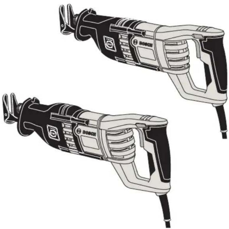
RS325 RS428
natural_image
Illustration of two Bosch electric drillers with visible internal components and wiring (no text or symbols)
BOSCH
Call Toll Free for Consumer Information & Service Locations
General Power Tool Safety Warnings

WARNING
Read all safety warnings and all instructions. Failure to follow the warnings and instructions may result in electric shock, fire and/or serious injury.
SAVE ALL WARNINGS AND INSTRUCTIONS FOR FUTURE REFERENCE
The term “power tool” in the warnings refers to your mains-operated (corded) power tool or battery-operated (cordless) power tool.
Work area safety
Keep work area clean and well lit. Cluttered or dark areas invite accidents.
Do not operate power tools in explosive atmospheres, such as in the presence of flammable liquids, gases or dust. Power tools create sparks which may ignite the dust or fumes.
Keep children and bystanders away while operating a power tool. Distractions can cause you to lose control.
Electrical safety
Power tool plugs must match the outlet. Never modify the plug in any way. Do not use any adapter plugs with earthed (grounded) power tools. Unmodified plugs and matching outlets will reduce risk of electric shock.
Avoid body contact with earthed or grounded surfaces such as pipes, radiators, ranges and refrigerators. There is an increased risk of electric shock if your body is earthed or grounded.
Do not expose power tools to rain or wet conditions. Water entering a power tool will increase the risk of electric shock.
Do not abuse the cord. Never use the cord for carrying, pulling or unplugging the power tool. Keep cord away from heat, oil, sharp edges or moving parts. Damaged or entangled cords increase the risk of electric shock.
When operating a power tool outdoors, use an extension cord suitable for outdoor use. Use of a cord suitable for outdoor use reduces the risk of electric shock.
If operating the power tool in damp locations is unavoidable, use a Ground Fault Circuit Interrupter (GFCI) protected supply. Use of an GFC' reduce the risk of electric shock.
Personal safety
Stay alert, watch what you are doing and use common sense when operating a
power tool. Do not use a power tool while you are tired or under the influence of drugs, alcohol or medication. A moment of inattention while operating power tools may result in serious personal injury.
Use personal protective equipment. Always wear eye protection. Protective equipment such as dust mask, non-skid safety shoes, hard hat, or hearing protection used for appropriate conditions will reduce personal injuries.
Prevent unintentional starting. Ensure the switch is in the off-position before connecting to power source and / or battery pack, picking up or carrying the tool.
Carrying power tools with your finger on the switch or energizing power tools that have the switch on invites accidents.
Remove any adjusting key or wrench before turning the power tool on. A wrench or a key left attached to a rotating part of the power tool may result in personal injury.
Do not overreach. Keep proper footing and balance at all times. This enables better control of the power tool in unexpected situations.
Dress properly. Do not wear loose clothing or jewelry. Keep your hair, clothing and gloves away from moving parts. Loose clothes, jewelry or long hair can be caught in moving parts.
If devices are provided for the connection of dust extraction and collection facilities, ensure these are connected and properly used. Use of dust collection can reduce dust-related hazards.
Power tool use and care
Do not force the power tool. Use the correct power tool for your application. The correct power tool will do the job better and safer at the rate for which it was designed.
Do not use the power tool if the switch does not turn it on and off. Any power tool that cannot be controlled with the switch is dangerous and must be repaired.
Disconnect the plug from the power source and/or the battery pack from the power tool before making any adjustments, changing accessories, or storing power tools. Such preventive safety measures reduce the risk of starting the power tool accidentally.
Store idle power tools out of the reach of children and do not allow persons unfamiliar with the power tool or these instructions to operate the power tool. Power tools are dangerous in the hands of untrained users.
Maintain power tools. Check for misalignment or binding of moving parts, breakage of parts and any other condition that may affect the power tool's operation. If damaged, have the power tool repaired before use.
Many accidents are caused by poorly maintained power tools.
Keep cutting tools sharp and clean. Properly maintained cutting tools with sharp cutting edges are less likely to bind and are easier to control.
Use the power tool, accessories and tool bits etc. in accordance with these instructions, taking into account the working conditions and the work to be performed. Use of the power tool for operations different from those intended could result in a hazardous situation.
Service
Have your power tool serviced by a qualified repair person using only identical replacement parts. This will ensure that the safety of the power tool is maintained.
Safety Rules for Reciprocating Saws
Hold power tool by insulated gripping surfaces when performing an operation where the cutting tool may contact hidden wiring or its own cord. Contact with a "live" wire will make exposed metal parts of the tool "live" and shock the operator.
Use clamps or another practical way to secure and support the workpiece to a stable platform. Holding the work by hand or against your body leaves it unstable and may lead to loss of control.
Never leave the trigger locked "ON". Before plugging the tool in, check that the trigger lock is "OFF". Accidental start-ups could cause injury.
Keep hands away from cutting area. Do not reach under the material being cut. The proximity of the blade to your hand is hidden from your sight.
Keep hands from between the gear housing and saw blade holder. The reciprocating blade holder can pinch your fingers.
Do not use dull or damaged blades. Bent blade can break easily or cause kickback.
Before starting to cut, turn tool "ON" and allow the blade to come to full speed. Tool can chatter or vibrate if blade speed is too slow at beginning of cut and possibly kickback.
Always wear safety goggles or eye protection when using this tool. Use a dust mask or respirator for applications which generate dust.
Secure material before cutting. Never hold it in your hand or across legs. Small or thin material may flex or vibrate with the blade, causing loss of control.
Make certain all adjusting screws and the blade holder are tight before making a cut.
Loose adjusting screws and holders can cause the tool or blade to slip and loss of control may result.
When removing the blade from the tool avoid contact with skin and use proper protective gloves when grasping the blade or accessory. Accessories may be hot after prolonged use.
When using the saw hook always be aware that the blade is exposed. Always hang the tool in an area where yourself and bystandards can not accidentally make contact with the blade.
Additional Safety Warnings
GFCI and personal protection devices like electrician's rubber gloves and footwear will further enhance your personal safety.
Do not use AC only rated tools with a DC power supply. While the tool may appear to work, the electrical components of the AC rated tool are likely to fail and create a hazard to the operator.
Keep handles dry, clean and free from oil and grease. Slippery hands cannot safely control the power tool.
Develop a periodic maintenance schedule for your tool. When cleaning a tool be careful not to disassemble any portion of the tool since internal wires may be misplaced or pinched or safety guard return springs may be improperly mounted.
Certain cleaning agents such as gasoline, carbon tetrachloride, ammonia, etc. may damage plastic parts.
Risk of injury to user. The power cord must only be serviced by a Bosch Factory Service Center or Autho rized Bosch Service Station.
WARNING
When operating the saw continuously and for
prolonged periods of time, the gearbox may become hot to the touch. To reduce the risk of injury, wear gloves during saw operation.
WARNING
Some dust created by power sanding, sawing, grinding,
drilling, and other construction activities contains chemicals known to cause cancer, birth defects or other reproductive harm. Some examples of these chemicals are:
- Lead from lead-based paints,
- Crystalline silica from bricks and cement and other masonry products, and
- Arsenic and chromium from chemically-treated lumber.
Your risk from these exposures varies, depending on how often you do this type of work. To reduce your exposure to these chemicals: work in a well ventilated area, and work with approved safety equipment, such as those dust masks that are specially designed to filter out microscopic particles.
Symbols
IMPORTANT: Some of the following symbols may be used on your tool. Please study them and learn their meaning. Proper interpretation of these symbols will allow you to operate the tool better and safer.
| Symbol Name Designation/Explanation | ||
| V Volts Voltage (potential) | ||
| A Amperes Current | ||
| Hz Hertz Frequency (cycles per second) | ||
| W Watt Power | ||
| kg Kilograms Weight | ||
| min Minutes Time | ||
| S | Seconds | Time |
| [26DH] | Diameter | Size of drill bits, grinding wheels, etc. |
| [HAB5] | No load speed | Rotational speed, at no load |
 | Rated speed | Manufacturers rated speed |
[YAB3] | Revolutions or reciprocation per minute | Revolutions, strokes, surface speed, orbits etc. per minute |
 | Off position | Zero speed, zero torque... |
1, 2  | Selector settings | Speed, torque or position settings. Higher number means greater speed |
| [208T] | 'infinitely variable selector with off | Speed is increasing from 0 setting |
| [56Y0] | Arrow | Action in the direction of arrow |
| [2283] | Alternating current | Type or a characteristic of current |
| [OKAV] | Direct current | Type or a characteristic of current |
| [888V] | Alternating or direct current | Type or a characteristic of current |
| [YXGH] | Class "construction | Designates Double 'nsulated Construction tools. |
 | ||
 | Earthing terminal | Grounding terminal |
 | Warning symbol | Alerts user to warning messages |
 | Li-ion RBRC seal | Designates Li-ion battery recycling program |
 | Ni-Cad RBRC seal | Designates Ni-Cad battery recycling program |
| [ABWZ] | Read manual symbol | Alerts user to read manual |
 | Wear eye protection symbol | Alerts user to wear eye protection |
Symbols (continued)
IMPORTANT: Some of the following symbols may be used on your tool. Please study them and learn their meaning. Proper interpretation of these symbols will allow you to operate the tool better and safer.

This symbol designates that this tool is listed by Underwriters Laboratories.

This symbol designates that this tool is listed by Underwriters Laboratories, to United States and Canadian Standards.

This symbol designates that this tool is listed by the Canadian Standards Association.

This symbol designates that this tool is listed by the Canadian Standards Association, to United States and Canadian Standards.

This symbol designates that this tool is listed by the 'ntertek Testing Services, to United States and Canadian Standards.

This symbol designates that this tool complies to NOM Mexican Standards.
Functional Description and Specifications

Disconnect the plug from the power source before making any assembly, adjustments or changing accessories. Such preventive safety be the risk of starting the tool accidentally.
Reciprocating Saw
FIG. 1
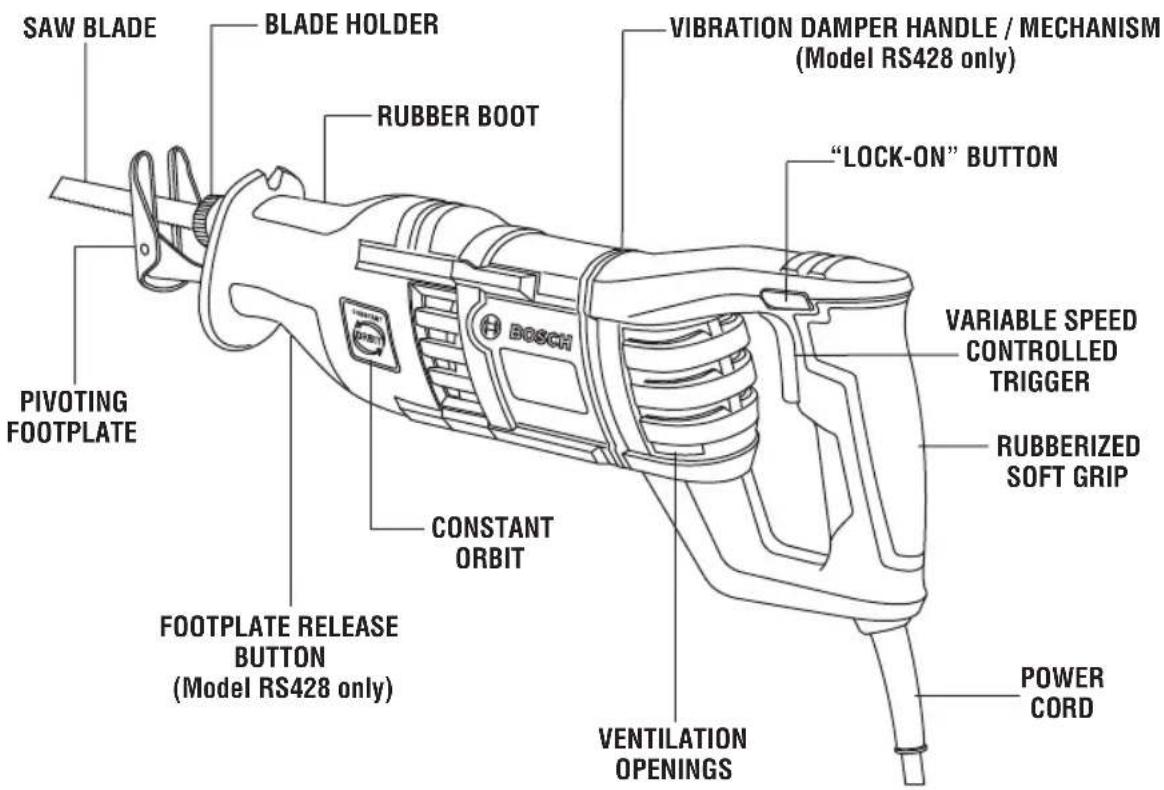
text_image
SAW BLADE BLADE HOLDER RUBBER BOOT PIVOTING FOOTPLATE CONSTANT ORBIT FOOTPLATE RELEASE BUTTON (Model RS428 only) VIBRATION DAMPER HANDLE / MECHANISM (Model RS428 only) "LOCK-ON" BUTTON VARIABLE SPEED CONTROLLED TRIGGER RUBBERIZED SOFT GRIP VENTILATION OPENINGS POWER CORDNOTE: For tool specifications refer to the nameplate on your tool.
Assembly
Preparing the Saw
BLADE SELECTION
No one blade can be efficient on all cutting jobs. Different materials require specially designed blades. Since your reciprocating saw can cut so many materials, many types of BOSCH blades are available. Be sure to use the proper blade to ensure proper cutting performance.
INSTALLING A BLADE
WARNING
Unplug tool from power source before changing blade or making any adjustments.
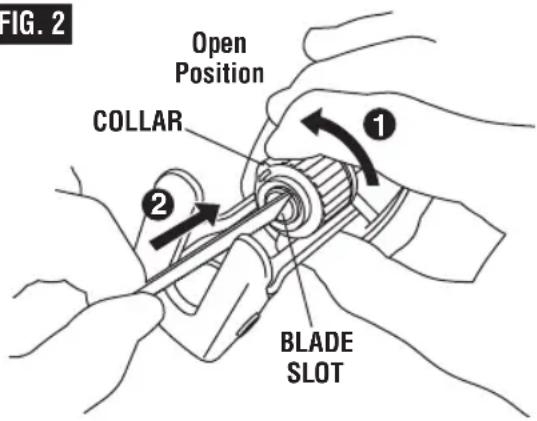
- Insert the blade into the blade holder by twisting the collar in direction of arrow until it stops (Fig. 2).
- Insert a blade into blade slot until blades shoulder rests against the collar.
- Release collar and spring loaded collar will securely clamp the blade. (Note: If the collar does not return to it's original position, rotate the collar in direction opposite of the arrow.)
4 Push in and pull out on the blade to be sure the pin in the clamp housing goes through the hole in the blade to hold the blade
securely. The blade may be inserted with the teeth facing down or up.
- To remove the blade, rotate the collar in direction of arrow while pulling the blade out of the blade slot. (Note: be careful, blade may be hot.)
WARNING
Make sure that the front end of the blade extends through the footplate for the entire stroke length. Do not use specialty blades that are very short or those with a significant cant. Blade must not contact footplate. A blade which is too short or tilted could jam inside the foot and snap.
FIG. 2
text_image
FIG. 2 Open Position COLLAR ① ② BLADE SLOTOperating Instructions
VARIABLE SPEED CONTROLLED TRIGGER SWITCH
Your tool is equipped with a variable speed controlled trigger switch. The tool can be turned "ON" or "OFF" by squeezing or releasing the trigger. The blade plunger stroke rate can be adjusted from the minimum to maximum nameplate stroke rate by the pressure you apply to the trigger. Apply more pressure to increase the speed and release pressure to decrease speed (Fig. 1).
"LOCK-ON" BUTTON
The "Lock-ON" button, located in the handle of your tool allows for continuous operation at maximum SPM without holding the trigger (Fig. 1).
TO LOCK TRIGGER "ON": squeeze trigger, depress button and release trigger.
TO UNLOCK THE TRIGGER: squeeze trigger and release it without depressing the "Lock-ON" button.
WARNING
If the "Lock-ON" button is continuously being depressed,
the trigger can not be released.
CONSTANT ORBIT
Your tool is equipped with the constant orbit mechanism that was designed to achieve the best cutting speeds in various materials (Fig. 1).
VIBRATION DAMPER HANDLE / MECHANISM
The integrated vibration damper in the main handle / mechanism reduces vibrations (Fig. 1).
FOOTPLATE ADJUSTMENT
The footplate tilts in order to keep as much of its surface in contact with the work surface Fig. 3 (a).
(Model RS428 only)
The footplate assembly can also be locked into one of three projection positions to optimize blade life and/or to reduce blade
protrusion beyond the end of the footplate, such as when cutting into large diameter pipe or into walls. To adjust the footplate position, simply push the footplate release button and move the footplate into the desired position. The locking mechanism is spring-loaded to lock into one of the 3 positions on the footplate assembly. 'f the footplate is pulled out so far that a notch shows at the other end of the shaft, the footplate assembly is extended too far out, and must be retracted to the one of the 3 positions Fig. 3 (b).
natural_image
Technical line drawing of a mechanical clamp or tool assembly (no text or symbols)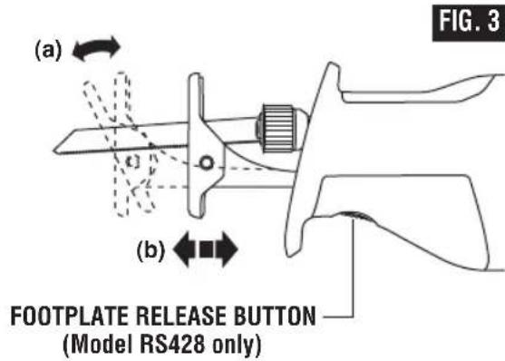
text_image
(a) (c) (b) FOOTPLATE RELEASE BUTTON (Model RS428 only) FIG. 3WARNING Do not push the footplate release button while sawing. 't will cause the footplate to release from the desired settings and you may lose control and be injured.
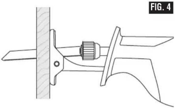
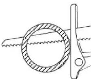
A WARNING To reduce the risk of injury, be sure the blade extends beyond the footplate and all the way through the workpiece throughout the stroke. Blades may shatter if the blade hits the footplate or hits the work at an angle that is nearly head-on (Fig. 4).
Using the Saw
- Securely clamp the work.
- Mark the line of cut and grasp the tool with one hand on the handle and the other placed on the insulated rubber boot over the front housing.
WARNING Always hold the saw by the insulated boot on the front housing. 'if you saw into a blind area where live wiring exists, you may be shocked or electrocuted.
- Keep the saw footplate firmly against the work to minimize counter-force (jumping) and vibration.
- Squeeze the trigger to start the tool. Let the saw reach full speed before starting the cut. Guide the saw so that the blade will move along the marked line.
SAWING TIPS
Following a few simple tips will reduce the wear on the workpiece, the tool and the operator.
-
Blades cut on the draw or back stroke. On fine work, such as paneling, fiberglass, etc., place the good side of workpiece facing down.
-
Use the correct saw blade for the material being cut and keep extra blades on hand to use when others become dull. Replace cracked or bent blades immediately.
- Select the appropriate cutting speed.
A WARNING To reduce the risk of injury, be sure the blade always extends beyond the footplate and work throughout the stroke. Blades may shatter if the front on the blade hits the work and/or the footplate.
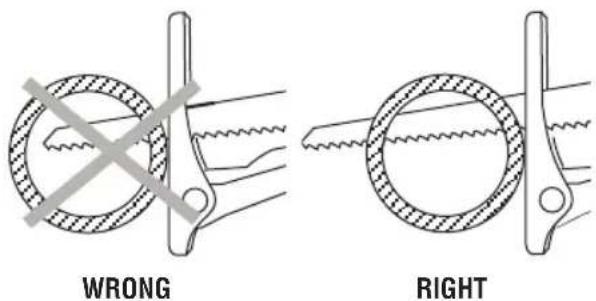
text_image
WRONG RIGHT- When cutting metal:
- Apply a lubricant for easier, smoother, faster cutting and longer blade life. - For non-ferrous metals, aluminum, bronze or brass, use a stick wax on the blade.
- For ferrous metals, iron and steel, use machine or cutting oil along the surface to be cut.
- When cutting thin metal, "sandwich" the material between two pieces of scrap wood. Clamp or put in a bench vise. One piece of lumber on top of the metal can be used with adequate clamping. Place your cut lines or design on the wood.
- Don't force the cutting. Let the saw and blade do the work.

WARNING
When operating the saw continuously and for prolonged periods of time, the gearbox may become hot to the touch. To reduce the risk of injury, wear gloves during saw operation.
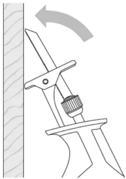
POCKET CUTS
POCKET/PLUNGE CUTS
The reciprocating saw can be used to make plunge cuts into softer material, (for example, wood or light building materials for walls), without a starting hole (Fig. 5).
- Mark the line to be cut clearly on the work.
- Set the tool with one edge of the footplate firmly against the material.
- Place the tip of the blade (not running) on the line to be cut.
- Tilt the saw so that the blade clears the work.
- Squeeze the trigger switch and carefully engage the moving saw blade into the material.
- After the blade penetrates through the work, continue sawing along the marked outline.
NOTES:
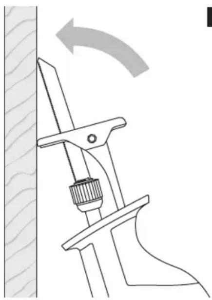
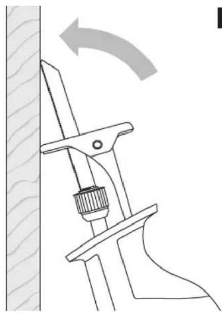
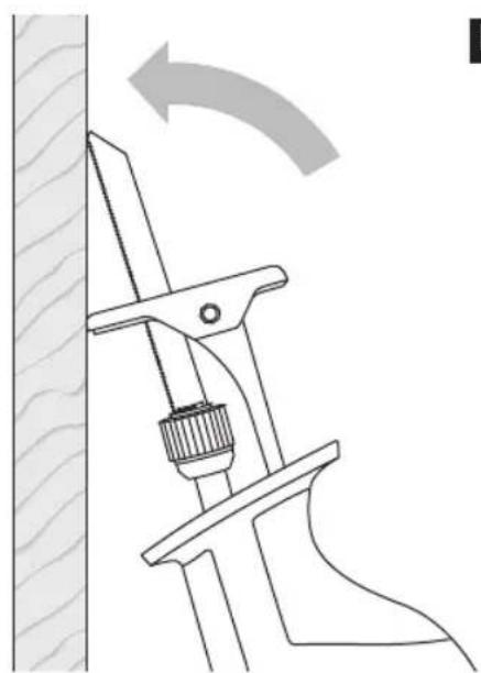
To make plunge cutting easier, use a heavy gauge blade, install the blade with the teeth facing upward, and hold the saw upside down as shown (Fig. 6).
Do not plunge cut in metal surfaces.
In thick materials and in harder materials, such as metal, plunge cutting should not be attempted. Such materials can be cut with the recip saw only by starting the cut from the edge of the material or from a hole drilled all the way through the material that is large enough to fit the saw blade.

WARNING
The use of any accessories not specified in this manual may create a hazard.
natural_image
Technical line drawing of a mechanical clamp or tool with a curved arrow indicating rotation (no text or symbols present)FIG. 5
natural_image
Technical line drawing of a mechanical clamp or tool against a textured wall, with no visible text or symbols.FIG. 6
Maintenance
Service
WARNING
Preventive maintenance performed by unauthorized per so n nel may result in misplacing of internal wires and components which could cause serious hazard. We recommend that all tool service be performed by a Bosch Factory Service Center or Autho - rized Bosch Service Station.
TOOL LUBRICATION
Your Bosch tool has been properly lubricated and is ready to use. 't is recommended that tools with gears be regreased with a special gear lubricant at every brush change.
CARBON BRUSHES
The brushes and commutator in your tool have been engineered for many hours of dependable service. To maintain peak efficiency of the motor, we recommend every two to six months the brush es be examined. Only genuine Bosch replace ment brushes specially designed for your tool should be used.
BEARINGS
Bearings which become noisy (due to heavy load or very abrasive material cutting) should be replaced at once to avoid overheating or motor failure.
Cleaning
WARNING
To avoid accidents always dis connect the tool from the power supply before cleaning or performing any main tenance. The tool may be cleaned most effectively with compressed dry air. Always wear safety goggles when cleaning tools with compressed air.
Ventilation openings and switch levers must be kept clean and free of foreign matter. Do not attempt to clean by inserting pointed objects through openings.
Use dry compressed air to clean dust and debris from the blade holder assembly on a regular basis.
Periodically lubricate blade holder with a dry lubricant such as graphite.
CAUTION
Certain cleaning agents and sol vents damage
plastic parts. Some of these are: gasoline, carbon tetrachloride, chlorinated cleaning solvents, ammonia and house hold detergents that contain ammonia.
Accessories
WARNING
If an extension cord is necessary, a cord with
adequate size conductors that is capable of carrying the current necessary for your tool must be used. This will prevent excessive voltage drop, loss of power or overheating. Grounded tools must use 3-wire extension cords that have 3-prong plugs and receptacles.
NOTE: The smaller the gauge number, the heavier the cord.
RECOMMENDED SIZES OF EXTENSION CORDS 120 VOLT ALTERNATING CURRENT TOOLS
| Tool's Ampere Rating | Cord Size in A.W.G. | Wire Sizes in mm^2 | ||||||
| Cord Length in Feet | Cord Length in Meters | |||||||
| 25 | 50 | 100 | 150 | 15 | 30 | 60 | 120 | |
| 3-6 | 18 | 16 | 16 | 14 | 0.75 | 0.75 | 1.5 | 2.5 |
| 6-8 | 18 | 16 | 14 | 12 | 0.75 | 1.0 | 2.5 | 4.0 |
| 8-10 | 18 | 16 | 14 | 12 | 0.75 | 1.0 | 2.5 | 4.0 |
| 10-12 | 16 | 16 | 14 | 12 | 1.0 | 2.5 | 4.0 | — |
| 12-16 | 14 | 12 | — | — | — | — | — | — |
* Carrying Case/Bag
* Blades
(*= standard equipment)
(**= optional accessories)
natural_image
Technical line drawing of a mechanical clamp or tool with a cylindrical component inserted, labeled 'FIG. 4' (no text or symbols on the diagram itself)natural_image
Diagram showing two mechanical clamping or fastening setups with no text or symbolsNON OUI
natural_image
Technical line drawing of a mechanical clamp or tool with a curved arrow indicating rotation (no text or symbols present)FIG. 5
natural_image
Technical diagram of a mechanical clamp or tool with a curved arrow indicating rotation (no text or symbols present)FIG. 6
Entretien
Service

AVERTISSEMENT
natural_image
Technical line drawing of a mechanical clamp or tool assembly (no text or symbols)Uso de la sierra
natural_image
Diagram showing a crossed-out ring with a diagonal line intersecting it, no text or symbols presentINCORRECTO
natural_image
Pure mechanical diagram showing a circular component with hatched fill and a diagonal tool, no text or symbols present.CORRECTO
natural_image
Technical line drawing of a mechanical clamp or tool with a curved arrow indicating rotation (no text or symbols present)FIG. 5
natural_image
Technical line drawing of a mechanical clamp or tool with a curved arrow indicating rotation (no text or symbols present)FIG. 6
Mantenimiento
Servicio
ADVERTENCIA
Robert Bosch Tool Corporation ("Seller") warrants to the original purchaser only, that all BOSCH portable and benchtop power tools will be free from defects in material or workmanship for a period of one year from date of purchase. SELLER'S SOLE OBLIGATION AND YOUR EXCLUSIVE REMEDY under this Limited Warranty and, to the extent permitted by law, any warranty or condition implied by law, shall be the repair or replacement of parts, without charge, which are defective in material or workmanship and which have not been misused, carelessly handled, or misrepaired by persons other than Seller or Authorized Service Station. To make a claim under this Limited Warranty, you must return the complete portable or benchtop power tool product, transportation prepaid, to any BOSCH Factory Service Center or Authorized Service Station. For Authorized BOSCH Power Tool Service Stations, please refer to your phone directory.
THIS LIMITED WARRANTY DOES NOT APPLY TO ACCESSORY ITEMS SUCH AS CIRCULAR SAW BLADES, DRILL BITS, ROUTER BITS, JIGSAW BLADES, SANDING BELTS, GRINDING WHEELS AND OTHER RELATED ITEMS.
ANY IMPLIED WARRANTIES SHALL BE LIMITED IN DURATION TO ONE YEAR FROM DATE OF PURCHASE. SOME STATES IN THE U.S., SOME CANADIAN PROVINCES DO NOT ALLOW LIMITATIONS ON HOW LONG AN IMPLIED WARRANTY LASTS, SO THE ABOVE LIMITATION MAY NOT APPLY TO YOU.
IN NO EVENT SHALL SELLER BE LIABLE FOR ANY INCIDENTAL OR CONSEQUENTIAL DAMAGES (INCLUDING BUT NOT LIMITED TO LIABILITY FOR LOSS OF PROFITS) ARISING FROM THE SALE OR USE OF THIS PRODUCT. SOME STATES IN THE U.S. AND SOME CANADIAN PROVINCES DO NOT ALLOW THE EXCLUSION OR LIMITATION OF INCIDENTAL OR CONSEQUENTIAL DAMAGES, SO THE ABOVE LIMITATION OR EXCLUSION MAY NOT APPLY TO YOU.
THIS LIMITED WARRANTY GIVES YOU SPECIFIC LEGAL RIGHTS, AND YOU MAY ALSO HAVE OTHER RIGHTS WHICH VARY FROM STATE TO STATE IN THE U.S., PROVINCE TO PROVINCE IN CANADA AND FROM COUNTRY TO COUNTRY.
THIS LIMITED WARRANTY APPLIES ONLY TO PORTABLE AND BENCHTOP ELECTRIC TOOLS SOLD WITHIN THE UNITED STATES OF AMERICA, CANADA AND THE COMMONWEALTH OF PUERTO RICO. FOR WARRANTY COVERAGE WITHIN OTHER COUNTRIES, CONTACT YOUR LOCAL BOSCH DEALER OR IMPORTER.
GARANTIE LIMITÉE DES OUTILS ÉLECTRIQUES PORTATIFS ET D'ÉTABLI BOSCH
© Robert Bosch Tool Corporation 1800 W. Central Road Mt. Prospect, IL 60056-2230
Exportado por: Robert Bosch Tool Corporation Mt. Prospect, IL 60056-2230, E.U.A.