GKS 18V-25 Professional - Saw BOSCH - Free user manual and instructions
Find the device manual for free GKS 18V-25 Professional BOSCH in PDF.

User questions about GKS 18V-25 Professional BOSCH
0 question about this device. Answer the ones you know or ask your own.
Ask a new question about this device
Download the instructions for your Saw in PDF format for free! Find your manual GKS 18V-25 Professional - BOSCH and take your electronic device back in hand. On this page are published all the documents necessary for the use of your device. GKS 18V-25 Professional by BOSCH.
USER MANUAL GKS 18V-25 Professional BOSCH
IMPORTANT Read Before Using
IMPORTANT Lire avant usage
IMPORTANTE Leer antes de usar

natural_image
Silhouette of a person reading a book inside a circle (no text or symbols)Operating/Safety Instructions Consignes d'utilisation/de sécurité Instrucciones de funcionamiento y seguridad
GKS18V-25G
natural_image
3D rendering of a mechanical power saw assembly (no visible text or symbols)
BOSCH
Call Toll Free for Consumer Information and Service Locations Pour obtenir des informations et les adresses de nos centres de service après-vente, appelez ce numéro gratuit Llame gratis para obtener información para el consumidor y ubicaciones de servicio
1-877-BOSCH99 (1-877-267-2499) www.boschtools.com
For English Version See page 2
| Safety SymbolsThe definitions below describe the level of severity for each signal word.Please read the manual and pay attention to these symbols. | |
 | This is the safety alert symbol. It is used to alert you to potential personal injury hazards. Obey all safety messages that follow this symbol to avoid possible injury or death. |
 | DANGER indicates a hazardous situation which, if not avoided, will result in death or serious injury. |
 | WARNING indicates a hazardous situation which, if not avoided, could result in death or serious injury. |
 | CAUTION indicates a hazardous situation which, if not avoided, could result in minor or moderate injury. |
General Power Tool Safety Warnings
WARNING
Read all safety warnings, instructions, illustrations and specifications provided with this power tool. Failure to follow all instructions listed below may result in electric shock, fire and/or
serious injury.
SAVE ALL WARNINGS AND INSTRUCTIONS FOR FUTURE REFERENCE
The term "power tool" in the warnings refers to your mains-operated (corded) power tool or battery-operated (cordless) power tool.
1. Work area safety
a. Keep work area clean and well lit. Cluttered or dark areas invite accidents.
b. Do not operate power tools in explosive atmospheres, such as in the presence of flammable liquids, gases or dust. Power tools create sparks which may ignite the dust or fumes.
c. Keep children and bystanders away while operating a power tool. Distractions can cause you to lose control.
2. Electrical safety
a. Power tool plugs must match the outlet. Never modify the plug in any way. Do not use any adapter plugs with earthed (grounded) power tools. Unmodified plugs and matching outlets will reduce risk of electric shock.
b. Avoid body contact with earthed or grounded surfaces, such as pipes, radiators, ranges and refrigerators. There is an increased risk of electric shock if your body is earthed or grounded.
c. Do not expose power tools to rain or wet conditions. Water entering a power tool will increase the risk of electric shock.
d. Do not abuse the cord. Never use the cord for carrying, pulling or unplugging the power tool.
2
Keep cord away from heat, oil, sharp edges or moving parts. Damaged or entangled cords increase the risk of electric shock.
e. When operating a power tool outdoors, use an extension cord suitable for outdoor use. Use of a cord suitable for outdoor use reduces the risk of electric shock.
f. If operating a power tool in a damp location is unavoidable, use a Ground Fault Circuit Interrupter (GFCI) protected supply. Use of an GFCI reduces the risk of electric shock.
3. Personal safety
a. Stay alert, watch what you are doing and use common sense when operating a power tool. Do not use a power tool while you are tired or under the influence of drugs, alcohol or medication. A moment of inattention while operating power tools may result in serious personal injury.
b. Use personal protective equipment. Always wear eye protection. Protective equipment such as dust mask, non-skid safety shoes, hard hat, or hearing protection used for appropriate conditions will reduce personal injuries.
c. Prevent unintentional starting. Ensure the switch is in the off-position before connecting to power source and / or battery pack, picking up or

General Power Tool Safety Warnings
carrying the tool. Carrying power tools with your finger on the switch or energizing power tools that have the switch on invites accidents.
d. Remove any adjusting key or wrench before turning the power tool on. A wrench or a key left attached to a rotating part of the power tool may result in personal injury.
e. Do not overreach. Keep proper footing and balance at all times. This enables better control of the power tool in unexpected situations.
f. Dress properly. Do not wear loose clothing or jewelry. Keep your hair, clothing and gloves away from moving parts. Loose clothes, jewelry or long hair can be caught in moving parts.
g. If devices are provided for the connection of dust extraction and collection facilities, ensure these are connected and properly used. Use of dust collection can reduce dust-related hazards.
h. Do not let familiarity gained from frequent use of tools allow you to become complacent and ignore tool safety principles. A careless action can cause severe injury within a fraction of a second.
4. Power tool use and care
a. Do not force the power tool. Use the correct power tool for your application. The correct power tool will do the job better and safer at the rate for which it was designed.
b. Do not use the power tool if the switch does not turn it on and off. Any power tool that cannot be controlled with the switch is dangerous and must be repaired.
c. Disconnect the plug from the power source and/or remove the battery pack, if detachable, from the power tool before making any adjustments, changing accessories, or storing power tools. Such preventive safety measures reduce the risk of starting the power tool accidentally.
d. Store idle power tools out of the reach of children and do not allow persons unfamiliar with the power tool or these instructions to operate the power tool. Power tools are dangerous in the hands of untrained users.
e. Maintain power tools and accessories. Check for misalignment or binding of moving parts, breakage of parts and any other condition that may affect the power tool's operation. If damaged, have the power tool repaired before use. Many accidents are caused by poorly maintained power tools.
f. Keep cutting tools sharp and clean. Properly maintained cutting tools with sharp cutting edges are less likely to bind and are easier to control.
g. Use the power tool, accessories and tool bits etc. in accordance with these instructions, taking into account the working conditions and the work to be performed. Use of the power tool for operations different from those intended could result in a hazardous situation.
h. Keep handles and grasping surfaces dry, clean and free from oil and grease. Slippery handles and grasping surfaces do not allow for safe handling and control of the tool in unexpected situations.
5. Battery tool use and care
a. Recharge only with the charger specified by the manufacturer. A charger that is suitable for one type of battery pack may create a risk of fire when used with another battery pack.
b. Use power tools only with specifically designated battery packs. Use of any other battery packs may create a risk of injury and fire.
c. When battery pack is not in use, keep it away from other metal objects like paper clips, coins, keys, nails, screws, or other small metal objects that can make a connection from one terminal to another. Shorting the battery terminals together may cause burns or a fire.
d. Under abusive conditions, liquid may be ejected from the battery, avoid contact. If contact accidentally occurs, flush with water. If liquid contacts eyes, additionally seek medical help. Liquid ejected from the battery may cause irritation or burns.
e. Do not use a battery pack or tool that is damaged or modified. Damaged or modified batteries may exhibit unpredictable behaviour resulting in fire, explosion or risk of injury.
f. Do not expose a battery pack or tool to fire or excessive temperature. Exposure to fire or temperature above 265 °F may cause explosion.
g. Follow all charging instructions and do not charge the battery pack or tool outside the temperature range specified in the instructions. Charging improperly or at temperatures outside the specified range may damage the battery and increase the risk of fire.
6. Service
a. Have your power tool serviced by a qualified repair person using only identical replacement parts. This will ensure that the safety of the power tool is maintained.
b. Never service damaged battery packs. Service of battery packs should only be performed by the manufacturer or authorized service providers.
Safety Instructions for Circular Saws
Cutting procedures
a. K

y from
BANDEN cutting area and the blade. Keep your second hand on auxiliary handle, or motor housing. If both hands are holding the saw, they cannot be cut by the blade.
b. Do not reach underneath the workpiece. The guard cannot protect you from the blade below the workpiece.
c. Adjust the cutting depth to the thickness of the workpiece. Less than a full tooth of the blade teeth should be visible below the workpiece.
d. Never hold the workpiece in your hands or across your leg while cutting. Secure the workpiece to a stable platform. It is important to support the work properly to minimize body exposure, blade binding, or loss of control.
e. Hold the power tool by insulated gripping surfaces, when performing an operation where the cutting tool may contact hidden wiring. Contact with a "live" wire will also make exposed metal parts of the power tool "live" and could give the operator an electric shock.
f. When ripping, always use a rip fence or straight edge guide. This improves the accuracy of cut and reduces the chance of blade binding.
g. Always use blades with correct size and shape (diamond versus round) of arbor holes. Blades that do not match the mounting hardware of the saw will run off-center, causing loss of control.
h. Never use damaged or incorrect blade washers or bolt. The blade washers and bolt were specially designed for your saw, for optimum performance and safety of operation.
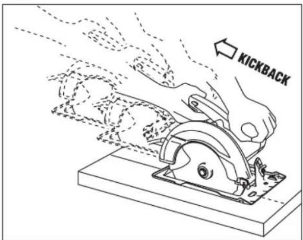
Kickback causes and related warnings
Kickback is a sudden reaction to a pinched, jammed or misaligned saw blade, causing an uncontrolled saw to lift up and out of the workpiece toward the operator.
When the blade is pinched or jammed tightly by the kerf closing down, the blade stalls and the motor reaction drives the unit rapidly back toward the operator.
If the blade becomes twisted or misaligned in the cut, the teeth at the back edge of the blade can dig into the top surface of the wood causing the blade to climb out of the kerf and jump back toward the operator.
Kickback is the result of saw misuse and/or incorrect operating procedures or conditions and can be avoided by taking proper precautions as given below:
a. Maintain a firm grip with both hands on the saw and position your arms to resist kickback forces. Position your body to either side of the blade, but not in line with the blade. Kickback could cause the
4
saw to jump backwards, but kickback forces can be controlled by the operator, if proper precautions are taken.
b. When blade is binding, or when interrupting a cut for any reason, release the trigger and hold the saw motionless in the material until the blade comes to a complete stop. Never attempt to remove the saw from the work or pull the saw backward while the blade is in motion or kickback may occur. Investigate and take corrective action to eliminate the cause of blade binding.
c. When restarting a saw in the workpiece, center the saw blade in the kerf so that the saw teeth are not engaged into the material. If a saw blade binds, it may walk up or kickback from the workpiece as the saw is restarted.
d. Support large panels to minimize the risk of blade pinching and kickback. Large panels tend to sag under their own weight. Supports must be placed under the panel on both sides, near the line of cut and near the edge of the panel.
e. Do not use dull or damaged blades. Unsharpened or improperly set blades produce narrow kerf causing excessive friction, blade binding and kickback.
f. Blade depth and bevel adjusting locking levers must be tight and secure before making cut. If blade adjustment shifts while cutting, it may cause binding and kickback.
g. Use extra caution when sawing into existing walls or other blind areas. The protruding blade may cut objects that can cause kickback.
Safety Instructions for Circular Saws
Lower Guard Function
a. Check the lower guard for proper closing before each use. Do not operate the saw if the lower guard does not move freely and close instantly. Never clamp or tie the lower guard into the open position. If the saw is accidentally dropped, the lower guard may be bent. Raise the lower guard with the retracting handle and make sure it moves freely and does not touch the blade or any other part, in all angles and depths of cut.
b. Check the operation of the lower guard spring. If the guard and the spring are not operating properly, they must be serviced before use. Lower guard may operate sluggishly due to damaged parts, gummy deposits, or a build-up of debris.
c. The lower guard may be retracted manually only for special cuts such as "plunge cuts" and "compound cuts". Raise the lower guard by the retracting handle and as soon as the blade enters the material, the lower guard must be released. For all other sawing, the lower guard should operate automatically.
d. Always observe that the lower guard is covering the blade before placing the saw down on bench or floor. An unprotected, coasting blade will cause the saw to walk backwards, cutting whatever is in its path. Be aware of the time it takes for the blade to stop after the switch is released.
Additional Safety Instructions for Circular Saws
a. Inspect the condition and quality of the wood and remove all nails from lumber before cutting. Wet lumber, green lumber or pressure treated lumber require special attention during cutting operation to prevent kickback.
b. Hold the saw firmly to prevent loss of control. Figures in this manual illustrate typical hand support of the saw.
c. Depending upon use, the switch may not last the life of the saw. If the switch should fail in the "OFF" position, the saw may not start. If it should fail while the saw is running, the saw may not shut off. If either occurs, remove the battery pack from the saw immediately and do not use until repaired.
d. This circular saw should not be mounted to a table and converted to a table saw. Circular saws are not designed or intended to be used as table saws.
e. The blade washers and the bolt on your saw have been designed to work as a clutch to reduce the intensity of a kickback. Understand the operation and settings of the VARI-TORQUE CLUTCH. The proper setting of the clutch, combined with firm handling of the saw will allow you to control kickback.
f. Never place your hand behind the saw blade.
Kickback could cause the saw to jump backwards over your hand.
g. Do not use the saw with an excessive depth of cut setting. Too much blade exposure increases the likelihood of the blade twisting in the kerf and increases the surface area of the blade available for pinching that leads to kickback.
h. Do not run the tool while carrying it at your side. Lower guard may be opened by a contact with your clothing. Accidental contact with the spinning saw blade could result in serious personal injury.
i. Periodically remove the blade, clean the upper, lower guards and the hub area with kerosene and wipe it dry. Preventive maintenance and properly operating guard will reduce the probability of an accident.
j. Ensure the switch is in the off position before inserting battery pack. Inserting the battery pack into power tools that have the switch on invites accidents.
k. Avoid overheating saw blade tips.
text_image
KICKBACKAdditional Safety Warnings
GFCI and personal protection devices like electrician's rubber gloves and footwear will further enhance your personal safety.
Develop a periodic maintenance schedule for your tool. When cleaning a tool be careful not to disassemble any portion of the tool since internal wires may be misplaced or pinched or safety guard return springs may be improperly mounted. Certain cleaning agents such as gasoline, carbon tetrachloride, ammonia, etc. may damage plastic parts.
WARNING
Some dust created by power sanding, sawing, grinding,
drilling, and other construction activities contains chemicals known to cause cancer, birth defects or other reproductive harm. Some examples of these chemicals are:
- Lead from lead-based paints,
- Crystalline silica from bricks and cement and other masonry products, and
- Arsenic and chromium from chemically-treated lumber.
Your risk from these exposures varies, depending on how often you do this type of work. To reduce your exposure to these chemicals: work in a well ventilated area, and work with approved safety equipment, such as those dust masks that are specially designed to filter out microscopic particles.
Symbols
Important: Some of the following symbols may be used on your tool. Please study them and learn their meaning. Proper interpretation of these symbols will allow you to operate the tool better and safer.
| Symbol Designation / Explanation | |
| V Volts (voltage) | |
| Ah Amp hour (measurement of battery capacity) | |
| A Amperes (current) | |
| Hz Hertz (frequency, cycles per second) | |
| W Watt (power) | |
| kg Kilograms (weight) | |
| min Minutes (time) | |
| s Seconds (time) | |
| ∅ | Diameter (size of drill bits, grinding wheels, etc.) |
| n_0 | No load speed (rotational speed at no load) |
| n Rated speed (maximum attainable speed) | |
| .../min Revolutions or reciprocation per minute (revolutions, strokes, surface speed, orbits etc. per minute) | |
| 0 Off position (zero speed, zero torque...) | |
| 1, 2, 3, ...I, II, III, | Selector settings (speed, torque or position settings. Higher number means greater speed) |
| Infinitely variable selector with off (speed is increasing from 0 setting) | |
| Arrow (action in the direction of arrow) | |
| Alternating current (type or a characteristic of current) | |
| Direct current (type or a characteristic of current) | |
| Alternating or direct current (type or a characteristic of current) | |
| Class II construction (designates double insulated construction tools) | |
| Earthing terminal (grounding terminal) | |
Symbols
Important: Some of the following symbols may be used on your tool. Please study them and learn their meaning. Proper interpretation of these symbols will allow you to operate the tool better and safer.
| Symbol Designation / Explanation | |
 | Alerts user to read manual |
 | Alerts user to wear eye protection |
 | This symbol designates that this tool is listed by Underwriters Laboratories. |
 | This symbol designates that this component is recognized by Underwriters Laboratories. |
 | This symbol designates that this tool is listed by Underwriters Laboratories, to United States and Canadian Standards. |
 | This symbol designates that this tool is listed by the Canadian Standards Association. |
 | This symbol designates that this tool is listed by the Canadian Standards Association, to United States and Canadian Standards. |
 | This symbol designates that this tool is listed by the Intertek Testing Services, to United States and Canadian Standards. |
 | Designates Li-ion battery recycling program |
 | Designates Ni-Cad battery recycling program |
Getting to Know Your Saw
WARNING
Disconnect battery pack from tool before making any assembly, adjustments or changing accessories. Such preventive safety measures reduce the risk of starting the tool accidentally.
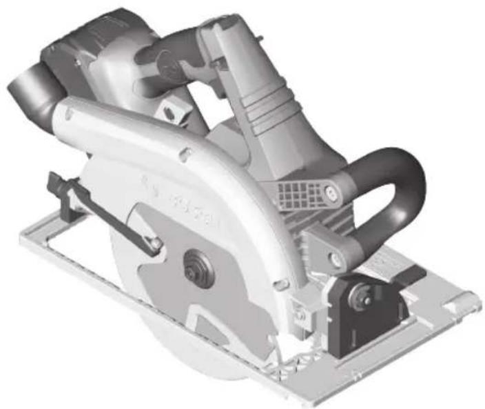
Cordless Circular Saw GKS18V-25G
Fig. 1

text_image
2621,22 1 2 3 4 5 6 7 8 9 10 11 12 13 14 15 16 17 18 191 Lock-off release buttons
2 Trigger switch
3 User interface
4 Auxiliary handle (insulated gripping surface)
5 Bevel adjustment lever
6 Wing nut (included with rip fence)
7 Bevel scale
8 Cutting line guide notch 0°
9 Cutting line guide notch 45°
10 Shaft lock button
11 Rip fence*
12 Lower guard
13 Foot
14 Lower guard lift lever (Retracting handle)
15 Bevel adjustment knob, rear
16 Upper guard
17 Cutting depth scale
18 Dust port
19 Battery pack
21 Depth control release button
22 Depth control locking button
23 Blade
24 Outer washer
25 Blade stud
26 Battery pack release button
27 Handle (insulated gripping surface)
28 Track Slots
* Sold separately
For track system refer to pages 22–27
Specifications
| Model number GKS18V-25G | |
| Voltage rating 18 V --- | |
| No load speed n | 0 2,500–5,000/min |
| Blade* 7-1/4" | |
| Blade arbor hole 5/8" (16mm) Round | |
| Blade tooth thickness | 7/64" (2.6mm)* *minimum 3/64" (1.0 mm) |
| Blade body thickness 0 | .079" (2.0mm) Maximum |
| Depth of cut at 0° 2-1/2" (63.5mm) Maximum | |
| Depth of cut at 45° 1-13/16" (46mm) Maximum | |
| Depth of cut at 50° 1-5/8" (41.3mm) Maximum | |
| Allowed ambient temperature – during charging – during operation and storage | 32...95 °F (0...+35 °C) -4...122 °F (-20...+50 °C) |
* For replacement blades we recommend Bosch Cordless Circular saw blades. Their thin kerf and tooth design deliver the superior speed, quality of cut, and reduce battery drain. Use of standard blades will substantially affect the performance and reduce run-time.
Battery Packs/Chargers
Please refer to the battery/charger list, included with your tool.
Intended Use
WARNING
Use this saw only as intended.
Unintended use may result in
personal injury and property damage.
This product is intended to cut wood and wood-like products only. Dust build up around the lower guard and hub from other materials (plastic, masonry or metal) may disable the lower guard operation.
Cutting Masonry/Metal
WARNING
Do not cut metal or masonry with this circular
saw. The dust from metal or masonry cutting will cause the lower guard to become sluggish and may not close fully and quickly after cutting these materials.
WARNING
Do not use abrasive wheels. This tool is not
intended for usage with metal or masonry cut-off wheels.
WARNING
Do not use Wet Diamond cutting off wheel or water
feed devices with this circular saw. Masonry cutting waste will enter the lower guard system, harden and cause the guard to become inoperable. Use of water in masonry cutting applications with an electric circular saw will cause electric shock hazards.
This tool is not intended for usage with metal or masonry cut-off wheels.
Saw Assembly
WARNING
Disconnect battery pack from tool before making any assembly, adjustments or changing accessories. Such preventive safety measures reduce the risk of starting the tool accidentally.
Inserting and Releasing Battery Pack
WARNING
Use only Bosch or Ampshare batteries recommended in
the battery/charger list, included with your tool. Using other types of batteries may result in personal injury or property damage.
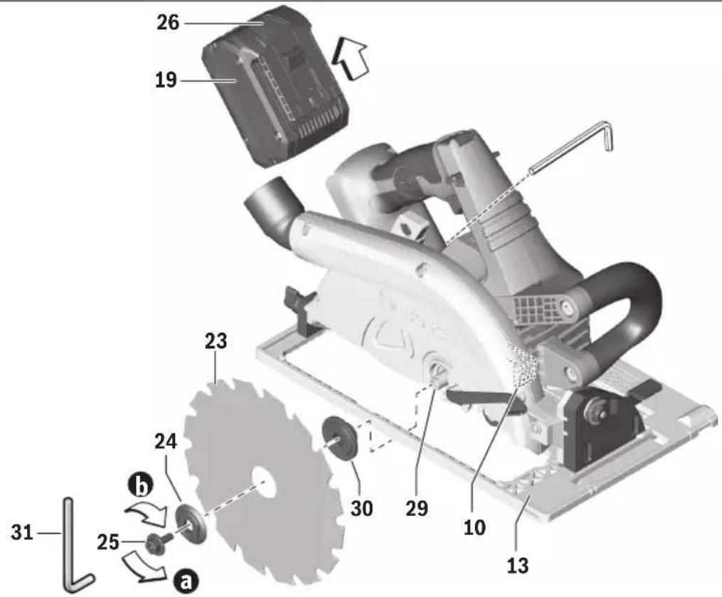
Slide charged battery pack 19 into the housing until the battery pack locks into position (Fig. 2).
Your tool is equipped with a secondary locking latch to prevent the battery pack from completely falling out of the handle, should it become loose due to vibration.
To remove the battery pack 19, press the battery pack release button 26 and slide the battery pack forward.
Press the battery pack release button 26 again and slide the battery pack completely out of tool housing (Fig. 2).
Attaching the Blade
WARNING
Use only 7-1/4" (184mm) blade. Use only blade
rated 5000/min (RPM) or greater. Using blade not designed for the saw may result in serious personal injury and property damage.
- Press and hold the shaft lock button 10. Turn blade stud 25 with provided wrench 31 in the direction a and remove blade stud 25 and outer washer 24. Note: the wrench is stored near the battery compartment (Fig. 2).
- Make sure the saw teeth and arrow on the blade point in the same direction as the arrow on the lower guard.
- Retract the lower guard all the way up into the upper guard. While retracting the lower guard, check operation and condition of the LOWER GUARD SPRING.
Fig. 2
text_image
26 19 23 24 30 29 10 13 31 25 aSaw Assembly
- Slide blade 23 through slot in the foot 13 and mount it against the inner washer 30 on the shaft 29. Be sure the large diameter of the outer washer 24 lays flush against the blade (Fig. 2).
- Reinstall outer washer and tighten blade stud 25 finger tight in the direction b. Press and hold lock button 10 to lock shaft and TIGHTEN BLADE STUD COUNTER-CLOCKWISE 1/4 TURN WITH THE WRENCH PROVIDED (Fig. 2).
Do not use wrenches with longer handles, since it may lead to over tightening of the blade stud.
VARI-TORQUE CLUTCH
This clutching action is provided by the friction of the outer washer 24 against the blade 23 and permits the blade shaft to turn when the blade encounters excessive resistance. When the blade stud 25 is properly tightened (as described in No. 5 of Attaching The Blade), the blade will slip when it encounters excessive resistance, thus reducing saw's tendency to KICKBACK.
One setting may not be sufficient for cutting all materials. If excessive blade slippage occurs, tighten the blade stud one mark more. OVERTIGHTENING THE BLADE STUD NULLIFIES THE EFFECTIVENESS OF THE CLUTCH.
Dust Extraction
WARNING
To reduce the risk of injury, always position
dust port and vacuum hose so that they do not interfere with the lower guard, or the cutting operation at all settings.
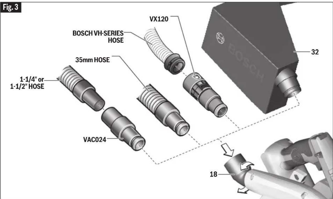
DUST PORT
The dust port 18 swivels so that dust can be directed in the desired direction (Fig. 3).
DUST BAG (sold separately)
Using Dust Bag - To attach the empty dust bag 32, press-fit its coupler end into the saw's dust port 18 (Fig. 3).
Cleaning Dust Bag – After the dust bag is 2/3 to 3/4 full, remove it from the saw. Bring the bag to a proper container and pull open the zipper located on the bottom of the bag. Hold the bag by the coupler end and shake it vigorously until all the dust and debris fall from it. Close zipper and reattach the bag.
NOTE: Clean the bag at the end of the cutting session and before transporting or storing the saw.
WARNING
Be extremely careful when disposing of dust.
Materials in fine particle form may be explosive. Do not throw sawdust on an open fire. Spontaneous combustion, in time, may result from the mixture of oil or water with dust particles.
text_image
Fig. 3 BOSCH VH-SERIES HOSE 35mm HOSE 1-1/4" or 1-1/2" HOSE VAC024 VX120 32 18Saw Assembly
CONNECTION TO VACUUM CLEANER / DUST EXTRACTOR
Connect the vacuum cleaner hose to the dust port (Fig. 3).
- Bosch VH-series hoses - The VX120 hose adapter is required (included with VH-series hoses).
- Other 35mm and 22mm hoses, such as the Bosch VAC-series hoses - Connect hose directly to the tool.
- Common 1 ^1/4 " or 1 ^1/2 " hoses - The Bosch VAC024 adapter is required (sold separately).
Connect the vacuum hose to a vacuum cleaner.
The vacuum cleaner must be suitable for the material being worked on.
When vacuuming dry dust that is especially detrimental to health or carcinogenic, use a special vacuum cleaner / dust extractor.
Brake Action
⚠ WARNING Let the saw blade come to a complete stop before setting the tool down. The brake action of this circular saw is not intended as a safety feature. Unintended contact with a rotating saw blade can cause property damage and/or personal injury.
WARNING Know the charge state of your battery. The electric braking action is initiated ONLY by the release of the trigger switch and in a tool that has power available. When electrical power is lost due to a discharged battery or other causes, the electric brake will not operate and the motor will gradually slow down. Unexpected run down time may cause property damage and/or personal injury.
Your circular saw is equipped with an automatic electric brake, which is designed to stop the saw blade from spinning in approximately two (2) seconds after you release the trigger switch. This feature helps improve jobsite productivity.
Braking starts once the power is turned off. The brake requires a charged battery to function. Stopping time will vary depending on, among other factors, saw blade used, and number of actuations. The electric brake of your circular saw has been designed for a high degree of reliability, but unexpected circumstances such as contamination or failure of the motor's components can cause the brake to not activate. If the tool operates but the brake does not consistently stop the blade in about 2 seconds, DO NOT use the circular saw and have it serviced by a Bosch Factory Service Center or Bosch authorized service facility.
Operating Instructions
WARNING
Disconnect battery pack from tool before
making any assembly, adjustments or changing accessories. Such preventive safety measures reduce the risk of starting the tool accidentally.
Depth Adjustment
WARNING
Adjust the cutting depth so that no more than one
tooth is visible below the work piece. Excessive blade exposure below the workpiece could result in personal injury and/or property damage.
WARNING
The depth adjustment system should be not used
to change the depth while the saw is in operation, or for plunge cutting. If blade adjustment shifts while cutting, it may cause binding and kickback.
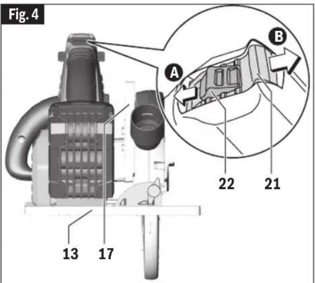
To adjust the cutting depth follow these instructions (Fig. 4):
A. Disconnect battery pack from tool.
B. Depressing the depth control locking button 22.
C. Slide the depth control release button 21 forward.
- For a smaller cutting depth, pull the saw away from the foot 13;
- for a deeper cutting depth, push the saw toward the foot 13. The cutting depth scale 17 has both inch and metric scales.
Note: Not more than one tooth length of the blade should extend below the material to be cut, for minimum splintering (Fig. 5).
90° Cutting Angle Check
A. Disconnect battery pack from tool.
B. Set foot to maximum depth of cut setting.
C. Loosen adjustment lever 5 and the rear bevel adjustment knob 15, set to 0° on bevel scale 7, retighten lever 5 and knob 15 (Fig. 5).
D. Check for 90° angle between the blade and bottom plane of foot 13 with a square (Fig. 6). If necessary, make adjustments by turning the small alignment screw 33 from bottom side of foot 13 with a 2.5 mm allen wrench [not included] (Fig. 6).
text_image
Fig. 4 A B 22 21 13 17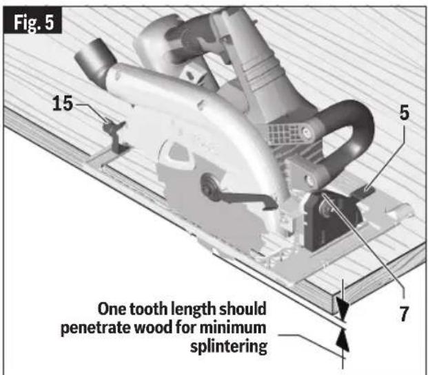
text_image
Fig. 5 15 5 One tooth length should penetrate wood for minimum splintering 7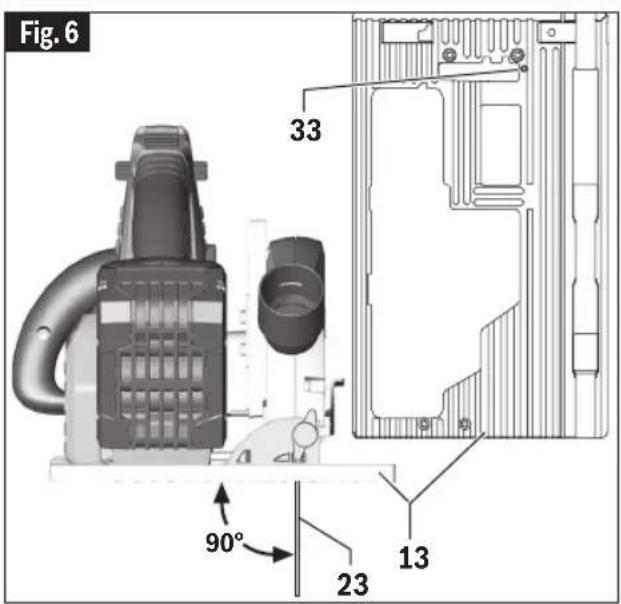
text_image
Fig. 6 33 90° 23 13Operating Instructions
Bevel Adjustment
A. Disconnect battery pack from tool.
B. Loosen the bevel adjustment lever 5 and the rear bevel adjustment knob 15.
C. Align to desired angle on the bevel scale 7. The foot can be adjusted up to 50°.
D. Tighten bevel adjustment knob 15 and lever 5 (Fig. 5).
Because of the increased amount of blade engagement in the work and decreased stability of the foot, blade binding may occur. Keep the saw steady and the foot firmly on the workpiece.
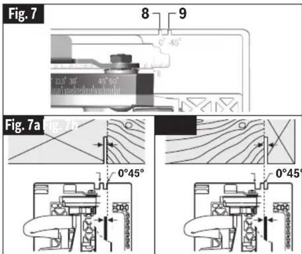
Cutting Line Guide Notches
The marked notches 8 and 9 at the front of the footplate indicate the approximate line of the cut (Fig. 7).
When track is not being used:
- For a non-bevelled cut, use 0^ notch 8.
- For 45^ and 50^ bevel cuts, use 45^ notch 9.
When track is being used:
- For both beveled and non-beveled cuts use 0^ notch 8.
For all cuts:
- To ensure minimum splintering on the good side of the material to be cut, face the good side down.
- Make sample cuts in scrap lumber to verify actual line of cut. This will be helpful because of the variety of blade types and thicknesses that are available.
- Use RIGHT side of notch when the part of the workpiece that is to the left of the blade is the scrap piece (Fig. 7a).
text_image
Fig. 7 8 9 0°45° 0°25'30' 45°50' Fig. 7a 0°45' 0°45'- Use LEFT side of notch when the part of the workpiece that is to the right of the blade is the scrap piece (Fig. 7b).
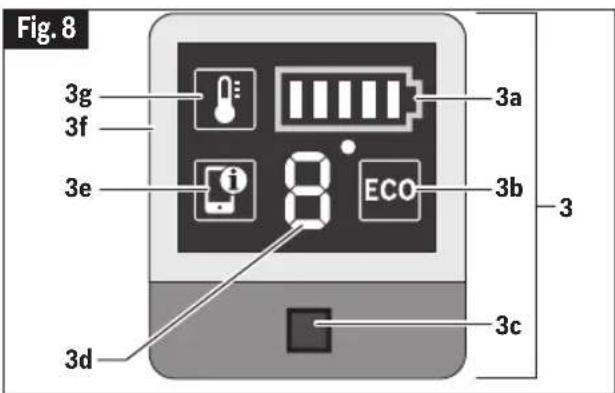
User Interface (Fig. 8)
text_image
Fig. 8 3g 3f 3e 8 3a 3b 3 3c 3dThe user interface 3 is used to select the preset speed levels and to indicate the status of the power tool and battery.
ECO MODE
When full power is not needed, the saw's energy-saving ECO mode can be used to reduce the saw's output power in order to extend the runtime. If the ECO mode is active, the speed level/mode indicator 3d displays the symbol "E" and "ECO" icon 3b lights up.
SPEED PRESETS
The speed settings and the ECO mode are preprogrammed. The table below describes the preset speeds and ECO mode speed.
| Preset Speeds | |
| Eco 3630/min | |
| 1 2500/min | |
| 2 3000/min | |
| 3 3500/min | |
| 4 4000/min | |
| 5 4500/min | |
| 6 5000/min |
Operating Instructions
BATTERY CHARGE INDICATOR
When the battery charge indicator 3a is glowing green, the battery is charged and the number of bars shows the level of the charge.
Glowing yellow and only one bar indicates that the battery needs to be charged or replaced soon.
Glowing red and only one bar means that the battery charge is depleted.
TEMPERATURE INDICATOR
If the temperature indicator 3g is glowing yellow, the critical temperature of the motor, electronics or battery has been reached. Run the power tool at no load and allow it to cool down.
If the temperature indicator is glowing red, power tool is overheated and will switch off. Allow the power tool to cool down.
POWER TOOL STATUS FRAME
Green light of the power tool status frame 3f means everything is functioning properly.
Yellow light means that:
a. Critical temperature has been reached (the temperature indicator 3g is also glowing yellow) - run the tool at no load and allow it to cool down, or
b. Battery is almost depleted (the battery charge indicator 3a is also glowing yellow) - charge or replace the battery soon.
Red light means that:
a. The tool is overheated (the temperature indicator 3g is glowing red) – turn the tool off and on again, or
b. Battery is depleted (the battery charge indicator 3a is also glowing red) - charge or replace the battery.
Lock-off Release Buttons
The Lock-off release buttons are designed to prevent accidental starts. To operate, press the release button 1 with your thumb on either side of handle to disengage the lock, then pull the trigger 2 (Fig. 1). When the trigger is released the button will engage the safety switch automatically, and the trigger will no longer operate.
Switch
When starting the tool, hold it with both hands. The torque from the motor can cause the tool to twist.
To turn tool on, press the lock-off release button 1 with your thumb on either side of handle to disengage the lock, then pull the trigger 2 (Fig. 1). To turn the tool "OFF", release the trigger switch, which is spring loaded and will return to the off position automatically.
Your saw should be running at full speed BEFORE starting the cut, and turned off only AFTER completing the cut. To increase switch life, do not turn switch on and off while cutting.
All Cuts
WARNING
Always be sure either hand does not interfere t of the lower guard.
with the free movement of the lower guard.
WARNING
After completing a cut and the trigger has been
released, be aware of the nec es sary time it takes for the blade to come to a com plete stop during coast down. Do not allow the saw to brush against your leg or side, since the lower guard is retractable, it could catch on your clothing and expose the blade. Be aware of the necessary blade ex posures that exist in both the upper and lower guard areas.
Always hold the saw handle with one hand and the auxiliary handle or housing with the other.
Always make sure saw foot rests on portion of work surface that does not drop off.
Maintain a firm grip and operate the switch with a decisive action. Never force the saw. Use light and continuous pressure.
When cutting is interrupted, to resume cutting: squeeze the trigger and allow the blade to reach full speed, re-enter the cut slowly and resume cutting.
When cutting across the grain, the fibers of the wood have a ten den cy to tear and lift. Advancing the saw slowly minimizes this effect. For a finished cut, a cross cut blade or miter blade is recommended.
Operating Instructions
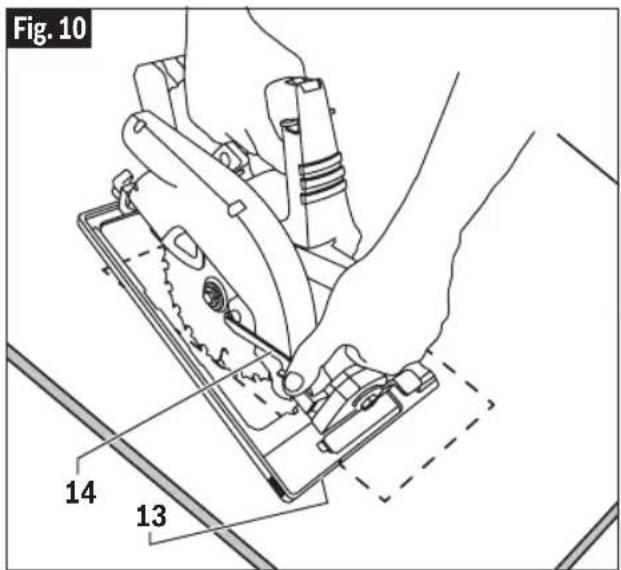
Plunge Cuts
WARNING
Adjust the cutting depth to the thickness of the
workpiece. Less than a full tooth of the blade teeth should be visible below the workpiece.
WARNING
The depth adjustment system should be not
used to change the depth while the saw is in operation, or for plunge cutting. If blade adjustment shifts while cutting, it may cause binding and kickback.
WARNING
As blade starts cutting the material, release the
lower guard immediately. When the foot rests flat on the surface being cut, proceed cutting in forward direction to end of cut.
WARNING
Allow blade to come to a complete stop before
lifting the saw from cut. Also, never pull the saw backward since blade will climb out of the material and KICKBACK will occur. Turn saw around and finish the cut in the normal manner, sawing forward. If corners of your pocket cut are not completely cut through, use a jigsaw or hand saw to finish the corners.
Disconnect battery pack from tool before making adjustments. Set depth adjustment according to material to be cut. Reattach battery pack to the saw. Tilt saw forward with cutting guide notch lined up with the line you've drawn. Raise the lower guard, using lift lever 14 and hold the saw by the front and rear handles (Fig. 10).
With the blade just clearing the material to be cut, start the motor. Gradually lower the back end of saw using the front end of the foot 13 as the hinge point.
Cutting Large Sheets
Large sheets and long boards sag or bend, depending on support. If you attempt to cut without leveling and properly supporting the piece, the blade will tend to bind, causing KICK-BACK and extra load on the motor (Fig. 11).
Support the panel or board close to the cut, as shown in (Fig. 12). Be sure to set the depth of the cut so that you cut through the sheet or board only and not the table or work bench. The two-by-fours used to raise and support the work should be positioned so that the broadest sides support the work and rest on the table or bench. Do not support the work with the narrow sides as this is an unsteady arrangement. If the sheet or board to be cut is too large for a table or work bench, use the supporting two-by-fours on the floor and secure.
text_image
Fig. 10 14 13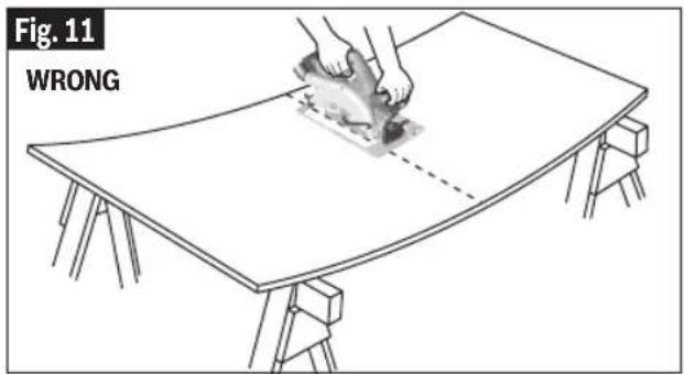
text_image
Fig. 11 WRONG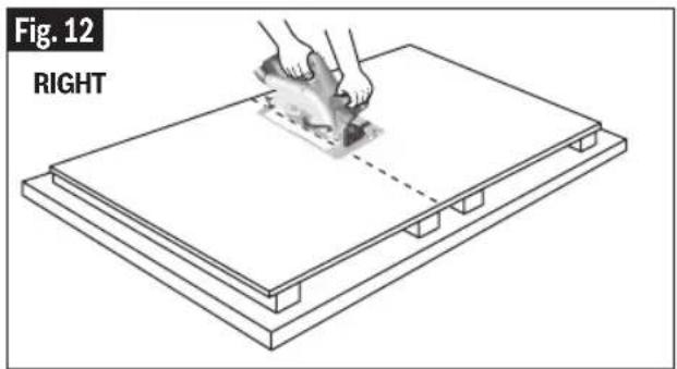
natural_image
Diagram showing hands using a tool to cut or spread material on a flat base plate (no text or symbols)Operating Instructions
Rip Cuts
WARNING
After attaching or adjusting the rip fence,
be sure the rip fence does not touch or interfere with the free movement of the lower guard or contact the saw blade.
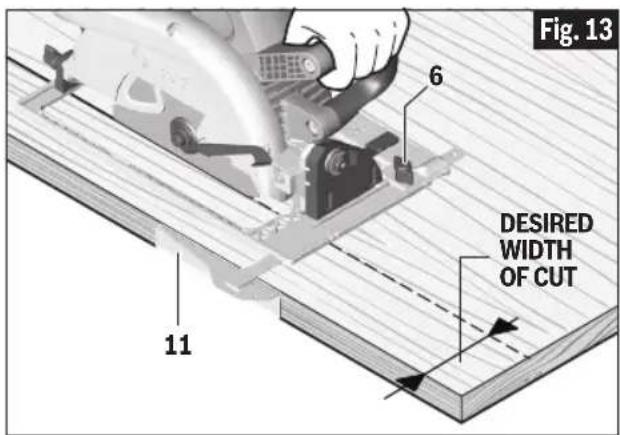
The combination blade provided with your saw is for both cross cuts and rip cuts. Ripping is cutting lengthwise with the grain of the wood. Narrow rip cuts are easy to do with a rip fence (Fig. 13). To attach optional rip fence 11, insert fence through slots in foot to desired width as shown and secure with the knob 6.
Rip Board Guide
When rip cutting large sheets, the rip fence may not allow the desired width of cut. Clamp or nail a straight piece of 1" (25 mm) lumber to the sheet as a guide (Fig. 14). Use the left side of the foot against the board guide.
The GKS18V-25G's auxiliary handle is designed to allow lumber as thick as 2x ("2-by") to be used as a guide.
text_image
Fig. 13 6 DESIRED WIDTH OF CUT 11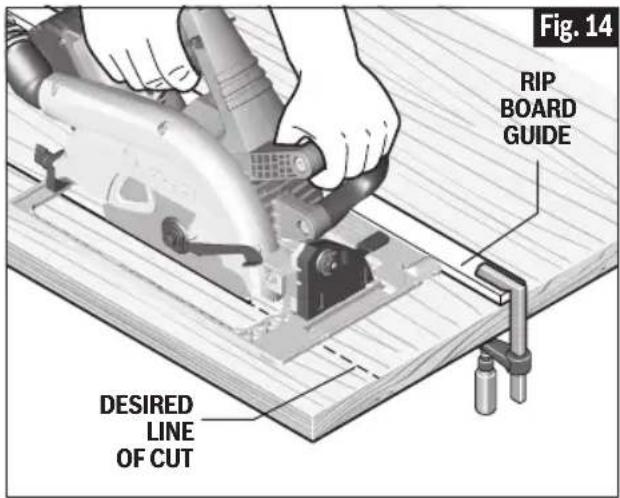
text_image
Fig. 14 RIP BOARD GUIDE DESIRED LINE OF CUTOperating Instructions
Precision Sawing With Track
WARNING
The depth adjustment system should be not used to change the depth while the saw is in operation, or for plunge cutting. If blade adjustment shifts while cutting, it may cause binding and kickback.
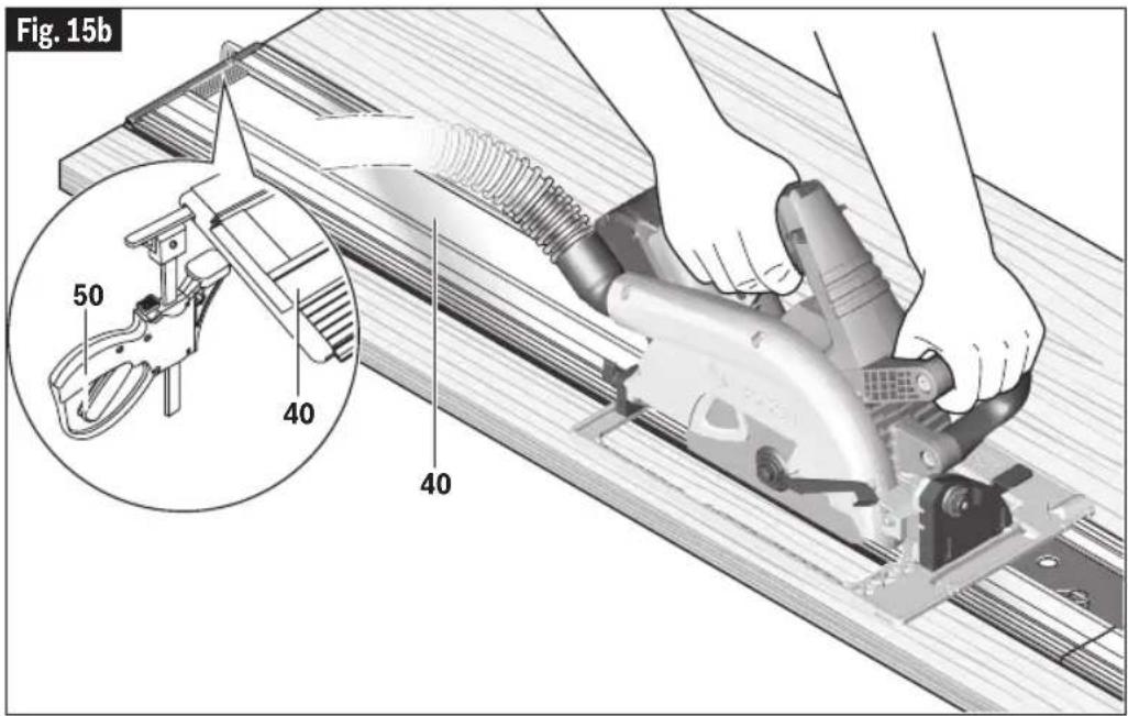
The GKS18V-25G can be used with the Bosch track system to enhance the straightness of the cut (Fig. 15b).
- Make sure that track 40 is prepared, positioned and clamped as shown in "Preparing Track" section on page 22.
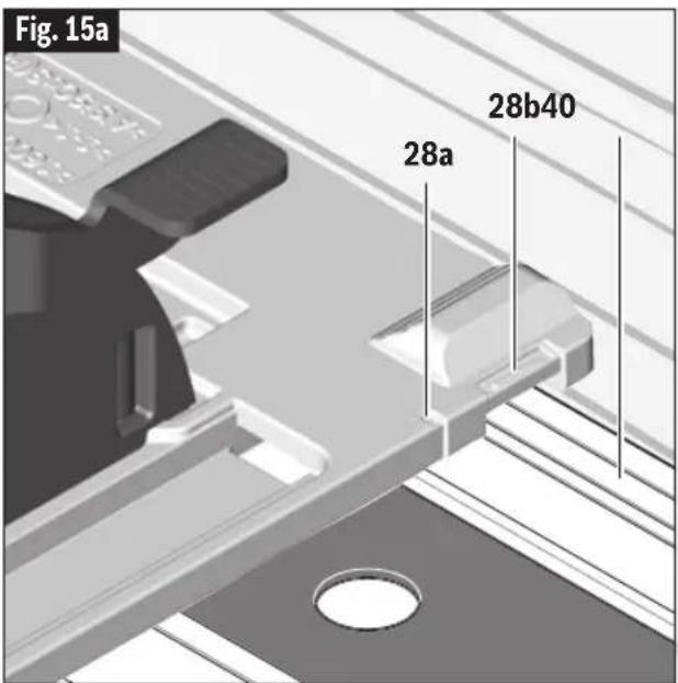
- Make sure that the saw's footplate is properly placed on track. This is achieved when the 28a slot on the bottom of the saw is placed over the raised ridge in the Bosch tracks (Fig. 15a). (The 28b slot will fit over some tracks from other manufacturers, but we recommend that this saw be used only with Bosch saw tracks.)
• Take extra care when placing saw on portion of a track that extends beyond the leading or ending edge of the workpiece. - Prior to removing saw from track, raise saw head and retract blade first and allow blade to
text_image
Fig. 15a 28a 28b40come to a complete stop.
text_image
Fig. 15b 50 40 40Getting to Know Your Track System
text_image
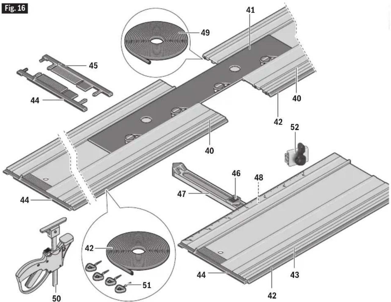
Fig. 16 49 41 45 44 40 42 52 40 46 48 47 43 42 44 43 51 42 5040 Track
41 Track Connector
42 Anti-splinter edge
43 Miter guide
44 End cap, left
45 End cap, right
46 Miter angle indicator
47 Fence
48 Miter locking knob
49 Traction strip
50 Track Clamps (x2)
51 Spikes
52 Travel Stop
The track system is sold separately
Track Assembly
ADAPTING THE FOOT PLATE TO VARIOUS TRACKS
The GKS18V-25G is designed specifically for precision straight cutting while using a track for guidance.
The Bosch tracks (sold separately) are available in four sizes:
| FSN800 31.5” (800 mm) |
| FSN1100 43.3” (1100 mm) |
| FSN1600 63” (1600 mm) |
| FSN2100 82.7” (2100 mm) |
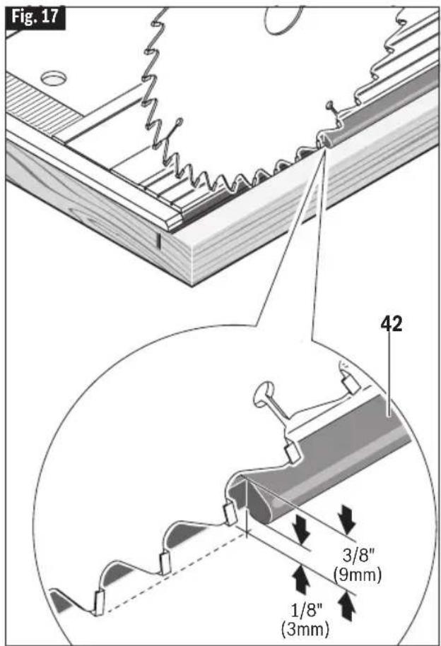
PREPARING TRACK
Prior to using a track for the first time, the track's rubber anti-splinter edge 42 must be adapted to the specific saw and blade to be used.
A. Place the complete length of track onto a scrap workpiece that is at least 3/4" (19mm) thick.
B. Secure the tracks as described in "SECURING TRACKS" further.
C. Place the saw onto the tracks.
D. Adjust the saw's cutting depth to approximately 3/8" (9 mm) and the bevel angle to 0°. This will result in the blade extending 1/8" (3mm) below the anti-splinter edge (Fig. 17).
E. Following the instructions in the "Switch" section on page 17, switch on the saw and guide it uniformly with a slow feed rate through the end of the track.
WARNING SECURING TRACKS
To avoid the risk of injury and/or property damage, only use the track clamps to secure the track.
Once the track has been placed in the desired position, insert a track clamp 50 in from each end of the track, then tighten the clamps against the workpiece (Fig. 18).
text_image
Fig. 17 42 3/8" (9mm) 1/8" (3mm)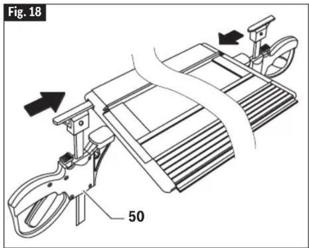
text_image
Fig. 18 50Track Assembly
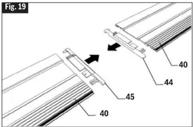
PROTECTIVE END CAPS
These caps help to protect the ends of the tracks from damage, such as when dropped on their ends (Fig. 19). The left 44 and right 45 caps are NOT interchangeable. If one or both of the end caps become damaged, they should simply be replaced.
CONNECTING MULTIPLE TRACKS
A. Pull out the end caps 44 and 45 from facing ends of the tracks 40 to be connected. Store the end caps in a safe place (Fig. 19).
B. Insert the connector 41 into one of the tracks 40 as shown and then slide another track onto the other end of the connector (Fig. 20).
C. Make sure that the tracks have no gap in between them. Move the connector 41 so that the center mark " | " is positioned at the joint line. Turn all four locks with a screw driver or a coin to secure the connection (Fig. 21).
text_image
Fig. 19 40 44 45 40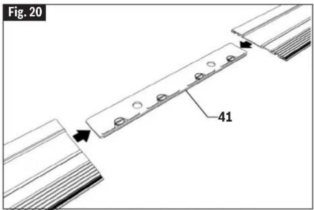
text_image
Fig. 20 41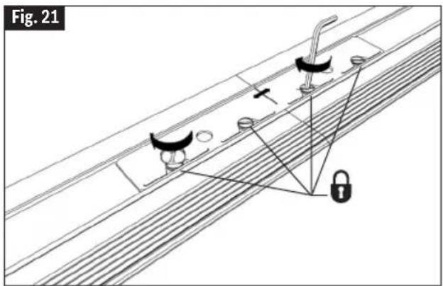
text_image
Fig. 21Track Assembly
MITER GUIDE
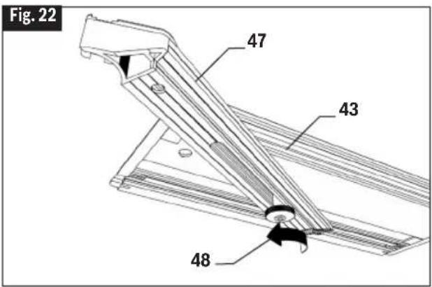
The miter guide 43 (sold separately) can be used to precisely position a track from 60° left to 45° right. The miter guide must be positioned at the front end of track.
A. Loosen the knob 48 on the bottom of the miter guide (Fig. 22).
B. Follow instructions in "Connecting Multiple Tracks" to attach the miter guide to the desired track using connector 41.
C. Use the fence 47 to set the desired angle. As the fence is moved, the indicator 46 shows the angle (Fig. 23).
D. Once the desired angle is set, tighten the knob 48 on the bottom of the miter guide to hold it at that angle (Fig. 24).
E. Position the fence and connected track such that the fence rests against the workpiece.
F. Once the miter guide and connected track have been positioned as desired, secure the miter guide and connected track in place (refer to "Securing Tracks").
text_image
Fig. 22 47 43 48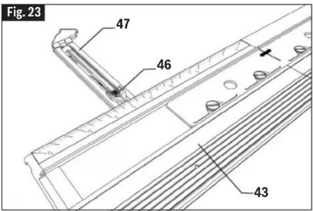
text_image
Fig. 23 47 46 43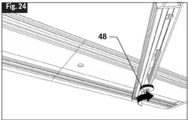
text_image
Fig. 24 48Track Assembly
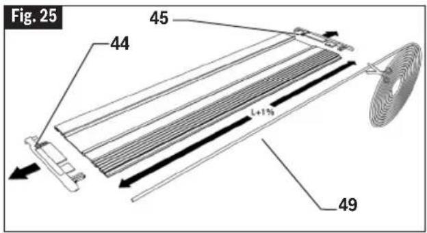
TRACTION STRIPS
It is important that the two rubberlike strips on the bottom of the tracks maintain their ability to minimize the possibility of the track shifting during a cut. If one or both of the strips become worn, they should be replaced. The traction strip roll is 11 feet (3.35m) long.
A. Pull out both end caps 44 and 45 and remove the worn out strips (Fig. 25).
B. Unroll and cut two lengths of traction strip 49 that are 1% longer than the length of the track. E.g. for FSN800 the length of strip should be 80.8cm/31.8" (Fig. 25).
C. Place a light coating of soap on the new strip to make it easier to slide in the grooves on the bottom side of tracks. Pull the strip though the groove to the far end of the track. Cut off the excess strips (Fig. 26).
D. Re-insert both end caps 44 and 45.
TRAVEL STOP FOR TRACK
The travel stop 52 (sold separately) can be used to limit the saw's range of travel (cutting distance) on a track. The stop can be used to help set the starting location of plunge cut or the end point of the cut.
A. Align the track along the intended cut line and clamp into place as described in "Securing Tracks" on page 23.
B. Orient the stop on the track as shown (Fig. 27).
C. Determine the desired start point or end point for the cut.
D. Position the saw such that it will sit in the position where the plunge cut is supposed to start or end.
E. Once the saw placed in the desired location, tighten the stop 52 in place using its lever (Fig. 28).
Move the saw forward to continue the cut until the desired endpoint. When the desired end point is reached, pull the saw's head up, and it will retract to the starting position, and the plunging mechanism becomes locked again.
text_image
Fig. 25 45 44 49 L+7%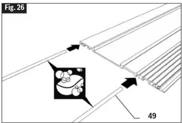
text_image
Fig. 26 49
text_image
Fig. 27 52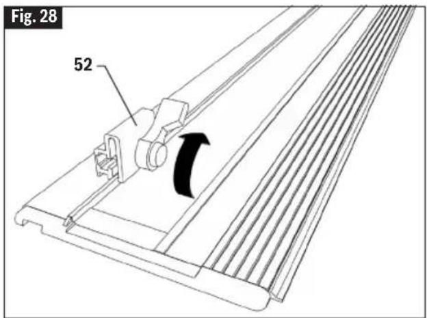
text_image
Fig. 28 52Track Assembly
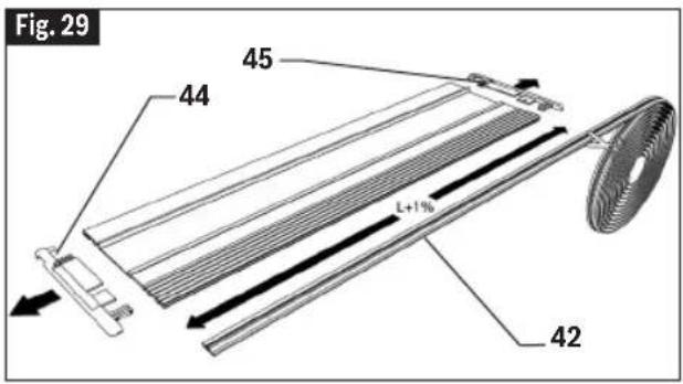
ANTI-SPLINTER EDGE
To minimize splintering of the workpiece, a worn edge should be replaced. The anti-splinter edge comes in a roll that is 11 feet (3.35m) long and can be cut to size for any given track.
A. Pull out both end caps 44 and 45 and remove the worn out anti-splinter edge. (Fig. 29).
B. Unroll and cut a length of anti-splinter edge 42 that is 1% longer than the length of the track. E.g. for FSN800 the length of strip should be 80.8cm/31.8" (Fig. 29).
C. Place a light coating of soap on the new edge to make it easier to slide in the grooves on the bottom side of track (Fig. 30).
D. Pull the edge though the groove to the far end of the track. Cut off the excess strips. To help prevent the anti-splinter strip from shifting, press one of the spikes 51 into the track alongside the strip at each end. Bend the spike's handle down to break off the handle (Fig. 31).
E. Re-insert the end caps 44 and 45.
F. See "Preparing Track" section on page 22 about adapting the anti-splinter edge to a given saw and blade.
CARRY BAG
The rugged bag accepts two FSN1600 tracks (or shorter) and has a pocket for a Connector and/or a pair of the track quick clamps.
text_image
Fig. 29 45 44 L+1% 42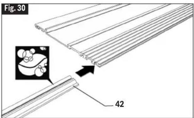
text_image
Fig. 30 42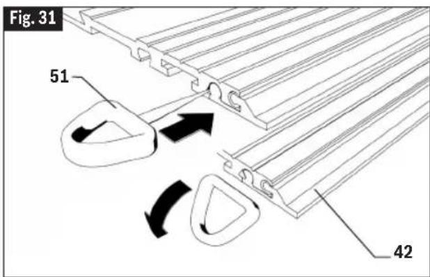
text_image
Fig. 31 51 42Maintenance
WARNING
To avoid accidents, always disconnect battery pack from tool before cleaning or performing any maintenance.
Service
WARNING
NO USER SERVICE-ABLE PARTS INSIDE.
Preventive maintenance performed by un authorized personnel may result in misplacing of internal wires and components which could cause serious hazard. We recommend that all tool service be performed by a Bosch Factory Service Center or Authorized Bosch Service Station.
Batteries
Be alert for battery packs that are nearing their end of life. If you notice decreased tool performance or significantly shorter running time between charges then it is time to replace the battery pack. Failure to do so can cause the tool to operate improperly or damage the charger.
Tool Lubrication
Your Bosch tool has been properly lubricated and is ready for use.
D.C. Motors
The motor in your tool has been engineered for many hours of dependable service. To maintain peak efficiency of the motor, we recommend it be examined every six months. Only a genuine Bosch replacement motor specially designed for your tool should be used.
Bearings
Bearings which become noisy (due to heavy load or very abrasive material cutting) should be replaced at once to avoid overheating and motor failure.
Cleaning
WARNING
Certain cleaning agents and solvents damage
plastic parts. Some of these are: gasoline, carbon tetrachloride, chlorinated cleaning solvents, ammonia and household detergents that contain ammonia.
Ventilation openings and switch levers must be kept clean and free of foreign matter. Do not attempt to clean by inserting pointed objects through opening.
Develop a periodic maintenance schedule for your tool. When cleaning a tool be careful not to disassemble any portion of the tool since internal wires may be misplaced or pinched or safety guard return springs may be improperly mounted. Certain cleaning agents such as gasoline, carbon tetrachloride, ammonia, etc. may damage plastic parts.
Care of Blades
Blades become dull even from cutting regular lumber. If you find yourself forcing the saw forward to cut instead of just guiding it through the cut, chances are the blade is dull or coated with wood pitch.
When cleaning gum and wood pitch from blade, remove the battery from the saw and remove the blade. Remember, blades are designed to cut, so handle carefully. Wipe the blade with kerosene or similar solvent to remove the gum and pitch. Unless you are experienced in sharpening blades, we recommend you do not try.
Accessories and Attachments

The use of any other attachments or acces so ries not specified in this manual may create a hazard.
Store accessories in a dry and temperate environment to avoid corrosion and deterioration.
| Bosch No. Description Included Sold Separately | |||
| Accessories | |||
| CBCL724 71⁄4" (184mm) thin kerf 24 tooth carbide blade ● ● | |||
| Attachments | |||
| 2610041761 Carry Bag ● ● | |||
| GKSRIP Rip fence - ● | |||
| 160541101V Dust Bag - ● | |||
| Various Vacuum Hoses - ● | |||
| VAC024 | Vacuum Hose Adapter for 1/14" and 1-1/2" Hoses | - | ● |
| FSN... | Tracks | - | ● |
| FSNKK | Track Clamps | - | ● |
| FSNVEL | Track Connector | - | ● |
| FSNWAN | Track Miter Guide | - | ● |
| FSNRS | Track Travel Stop | - | ● |
| FSNSS | Anti-splinter Edge | - | ● |
| FSNHB | Traction Strip | - | ● |
| FSNBAG | Carry Bag | - | ● |
Cutting Masonry/Metal
AVERTISSEMENT
text_image
Fig. 17 42 3/8" (9mm) 1/8" (3mm)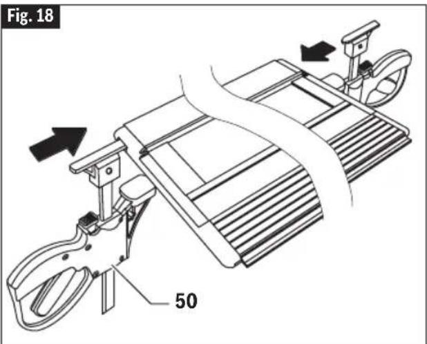
text_image
Fig. 18 50Montage des rails
RACCORDEMENT DE PLUSIEURS RAILS
text_image
Fig. 17 42 3/8" (9mm) 1/8" (3mm)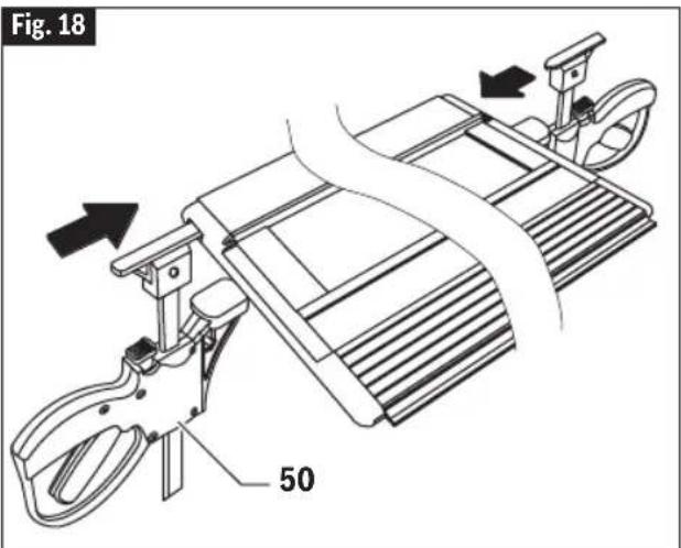
text_image
Fig. 18 50TAPAS DE EXTREMO PROTECTORAS
For details on the terms of the limited warranty for this product, go to https://rb-pt.io/PowerToolWarranty or call 1-877-BOSCH99.
GARANTIE LIMITÉE
© Robert Bosch Tool Corporation
1800 W. Central Road
Mt. Prospect, IL 60056-2230
160992A9PY 05/2024

text_image
Black and white barcode image with vertical lines and patterns1 6 0 9 9 2 A 9 P Y