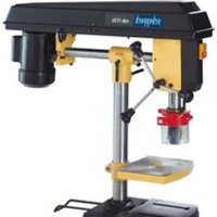
DP55Max - Drill SCHEPPACH - Free user manual and instructions
Find the device manual for free DP55Max SCHEPPACH in PDF.


User questions about DP55Max SCHEPPACH
0 question about this device. Answer the ones you know or ask your own.
Ask a new question about this device
Download the instructions for your Drill in PDF format for free! Find your manual DP55Max - SCHEPPACH and take your electronic device back in hand. On this page are published all the documents necessary for the use of your device. DP55Max by SCHEPPACH.
USER MANUAL DP55Max SCHEPPACH
Table of contents: Page:
- Explanation of the symbols on the device 19
- Introduction 20
- Device description (fig. 1-6, 11, 12) 20
- Scope of delivery 20
- Proper use 21
- Safety instructions 21
- Technical data 23
8.Before commissioning 24 - Assembly 24
- Operation 24
- Transport 26
- Cleaning and maintenance 26
- Storage 26
- Electrical connection 27
- Disposal and recycling 27
- Troubleshooting 28
1. Explanation of the symbols on the device
Symbols are used in this manual to draw your attention to potential hazards. The safety symbols and the accompanying explanations must be fully understood. The warnings themselves will not rectify a hazard and cannot replace proper accident prevention measures.
| Warning! Potential danger to life, risk of injury or damage to the tool when ignoring the instructions. | |
| Before commissioning, read and observe the operating instructions and safety instruc-tions! | |
| Wear safety goggles! | |
| Wear hearing protection! | |
| If dust builds up, wear respiratory protection! | |
| Do not wear long hair uncovered. Use a hair net. | |
| Do not wear gloves. | |
| Protection class II (double shielded) | |
| Attention! Laser beam |
2. Introduction
Manufacturer: scheppach
We hope your new tool brings you much enjoyment and success.
Note:
In accordance with the applicable product liability laws, the manufacturer of this device assumes no liability for damage to the device or caused by the device arising from:
- Improper handling,
- Failure to comply with the operating instructions.
- Repairs carried out by third parties, unauthorised specialists.
- Installing and replacing non-original spare parts,
Application other than specified, - A breakdown of the electrical system that occurs due to the non-compliance of the electric regulations and VDE regulations 0100, DIN 57113 / VDE0113.
We recommend:
Read through the complete text in the operating instructions before installing and commissioning the device.
The operating instructions are intended to help the user to become familiar with the machine and take advantage of its application possibilities in accordance with the recommendations.
The operating instructions contain important information on how to operate the machine safely, professionally and economically, how to avoid danger, costly repairs, reduce downtimes and how to increase reliability and service life of the machine.
In addition to the safety regulations in the operating instructions, you have to meet the applicable regulations that apply for the operation of the machine in your country.
Keep the operating instructions package with the machine at all times and store it in a plastic cover to protect it from dirt and moisture. Read the instruction manual each time before operating the machine and carefully follow its information.
The machine can only be operated by persons who were instructed concerning the operation of the machine and who are informed about the associated dangers. The minimum age requirement must be complied with.
In addition to the safety instructions contained in this operating manual and the specific regulations of your country, the technical rules generally accepted for the operation of machines of the same type must be observed.
We accept no liability for damage or accidents which arise due to non-observance of these instructions and the safety information.
3. Device description (fig. 1-6, 11, 12)
- Base plate
- Quick clamp
- Column
- Toothed rack for height adjustment
- Clamping lever for height adjustment
- Clamping lever for depth stop
- Depth stop
- Handle
- Display
- Off switch
- On switch
- Control unit
- Chuck guard
- Chuck
- Wing screws for parallel stop
- Parallel stop
- Quick-clamp screw
- Pointer
- Retaining screw
- Scale
- Inspection door
4. Scope of delivery
1 Drilling machine
1 Quick clamp (2)
1 Base plate (1)
1 Parallel stop (16)
1 Handle (8)
1 Spacer sleeve (K)
1 Chuck guard (13)
- 2 Screws 3,0 × 12 (C)
1 Clamping lever (6)
1 Allen key, 4 mm (L)
1 Chuck key (G)
1 Operating manual
1 Assembly material (N)
- 1 Nut (J)
1 Allen screw (B)
5. Proper use
The bench drill is designed for drilling in metal, wood, plastic and tiles.
Chuck clamping range: 1.5 - 13 mm.
The device is intended to be used by do-it-yourselfers. It was not designed for heavy commercial use. The tool is not to be used by persons under the age of 16. Children over the age of 16 may use the tool except under supervision. The manufacturer is not liable for damage caused by an improper use or incorrect operation of this device.
Please observe that our equipment was not designed with the intention of use for commercial or industrial purposes. We assume no guarantee if the equipment is used in commercial or industrial applications, or for equivalent work.
6. Safety instructions
General safety instructions for electric tools
WARNING! Read all safety instructions, information, illustrations and technical data for this electric tool. Failure to observe the following information and instructions can result in electric shock, fire and/or serious injuries.
Store all safety instructions and information for future reference.
The term "electric tool" used in the safety instructions refers to mains-powered electric tools (with a mains cable) or battery-powered electric tools (without a mains cable).
Workplace safety
a) Keep your work area clean and well-lit. Dis-organised or unlit work areas can result in accidents.
b) Do not work with the electric tool in an explosive environment where flammable liquids, gases or dusts may be located. Electric tools produce sparks that may ignite dust or vapours.
c) Keep children and other people away while using the electric tool. Distractions may cause you to lose control of the electric tool.
Electrical safety
a) The electrical tool's connection plug must fit into the socket. The plug may not be modified in any way. Do not use an adaptor plug together with earthed electric tools. Unmodified plugs and suitable sockets reduce the risk of an electric shock.
b) Avoid body contact with earthed surfaces, such as pipes, heaters, ovens and refrigerators. There is an increased risk of electric shock if your body is earthed.
c) Keep electric tools away from rain and moisture. Water entering an electric tool increases the risk of an electric shock.
d) Do not use the cable for another purpose, for example, carrying or hanging the electric tool or pulling the plug out of the socket. Keep the cable away from heat, oil, sharp edges or moving device parts. Damaged or coiled cables increase the risk of an electric shock.
e) If you work with an electric tool outdoors, only use extension cables that are also suitable for outdoor use. Using an extension cable suitable for outdoor use reduces the risk of an electric shock.
f) If you cannot avoid using the electrical tool in a wet environment, use a fault-current circuit breaker. Using a fault-current circuit breaker reduces the risk of an electric shock.
Safety of personnel
a) Remain attentive, pay attention to what you are doing and be sensible when working with electric tools. Do not use an electric tool if you are tired or under the influence of drugs, alcohol or medication. A moment of carelessness when using electrical tools can result in serious injuries.
b) Wear personal protective equipment and always wear safety goggles. Protective equipment such as a dust mask, non-skid safety shoes, hard hat or hearing protection used for appropriate conditions will reduce personal injuries.
c) Avoid unintentional startup. Make sure that the electric tool is switched off before you connect it the power supply and/or battery, pick it up or carry it. Carrying power tools with your finger on the switch or energising power tools that have the switch on invites accidents.
d) Remove the setting tools or spanners before switching on the electric tool. A tool or spanner that is located in a rotating device part may result in injuries.
e) Avoid abnormal posture. Make sure that you have secure footing and always maintain your balance. This will allow you to better control the electric tool in unexpected situations.
f) Wear suitable clothing. Do not wear wide clothing or jewellery. Keep hair, clothing and gloves away from moving parts. Loose clothing, jewellery and long hair can be caught by moving parts.
g) If dust extraction and collection devices can be mounted, make sure that they are connected and used properly. Using a dust extraction unit can reduce hazards caused by dust.
h) Do not allow yourself to be lulled into a false sense of security and do not ignore the safety rules for electric tools, even when you have used them many times and have become familiar with them. Careless actions can result in serious injuries within a fraction of a second.
Using and handling the electric tool
a) Do not overload the device. Use the electric tool intended for your work. The suitable electric tool allows you to work better and more safely in the indicated power range.
b) Do not use an electric tool whose switch is defective. An electric tool that cannot be switched on or off is dangerous and must be repaired.
c) Remove the plug from the socket and/or take out a removable battery before setting the device, changing insertion tool parts or putting the electric tool away. These precautionary measures will prevent the electric tool from starting unintentionally.
d) Keep unused electric tools out of the reach of children. Do not let people use the electric tool who are not familiar with it or who have not read these instructions. Electric tools are dangerous if they are used by inexperienced people.
e) Maintain electric tools and tool attachments with care. Check whether moving parts function properly and do not get stuck and whether parts are broken or are damaged and thus adversely affect the electric tool function. Have damaged parts repaired before using the electric tool. Many accidents are caused by poorly maintained electric tools.
f) Always keep cutting tools sharp and clean. Carefully maintained cutting tools with sharp cutting edges seize up less often and are easier to guide.
g) Use electric tools, accessories, insertion tool, etc. according to these instructions. Take the working conditions and the activity to be carried out into consideration. Using electric tools for applications other than the intended uses can lead to dangerous situations.
h) Keep the handles and gripping surfaces dry, clean and free of oil and grease. Slippery handles and gripping surfaces prevent safe operation and control of the electrical tool in unforeseen situations.
Service
a) Only have your electric tool repaired by qualified specialists and only with original spare parts. This ensures that safety of the electric tool is maintained.
Safety instructions for drills
a) The drill must be secured. An incorrectly secured drill can move or topple and this can result in injuries.
b) The workpiece must be clamped or fastened to the workpiece support. Do not drill into workpieces that are too small to be securely clamped. Holding the workpiece by hand can lead to injuries.
c) Do not wear gloves. Gloves can be caught by rotating parts or drilling debris and thus cause injuries.
d) Keep your hands away from the drilling area whilst the electrical tool is running. Contact with rotating parts or drilling debris can cause injuries.
e) The drill must be turning before it makes contact with the workpiece. Otherwise, the drill bit can catch in the workpiece and this can result in an unexpected movement of the workpiece and cause injuries.
f) If the drill becomes jammed, stop pressing downwards and switch the electrical tool off. Investigate and rectify the cause of the jamming. Jamming can result in an unexpected movement of the workpiece and can result in serious injuries.
g) Avoid long pieces of drill swarf by interrupting the downward pressure at regular intervals. Sharp metal swarf can become tangled and lead to injuries.
h) Never remove drilling debris from the drilling area whilst the electrical tool is running. To remove swarf, move the drill away from the workpiece, switch off the electrical tool and wait until the drill has come to a standstill. Use an aid such as a brush or a hook to remove the swarf. Contact with rotating parts or drilling debris can cause injuries.
i) The permissible rotational speed for drill bits with a rated speed must be at least as high as the highest speed cited on the electrical tool. Accessories that rotate faster than permitted can break and fly off at high speed.

Attention: Laser radiation Do not look into the beam Laser class 2
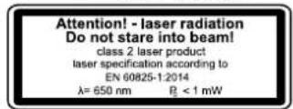
Protect yourself and you environment from accidents using suitable precautionary measures!
- Do not look directly into the laser beam with unprotected eyes.
- Never look into the path of the beam.
- Never point the laser beam towards reflecting surfaces and persons or animals. Even a laser beam with a low output can cause damage to the eyes.
- Caution - methods other than those specified here can result in dangerous radiation exposure.
- Never open the laser module. Unexpected exposure to the beam can occur.
- The laser may not be replaced with a different type of laser.
- Repairs of the laser may only be carried out by the laser manufacturer or an authorised representative.
- Labelling and placement of warning stickers, see fig. 8 and 9.
WARNING! This electric tool generates an electromagnetic field during operation. This field can impair active or passive medical implants under certain conditions. In order to prevent the risk of serious or deadly injuries, we recommend that persons with medical implants consult with their physician and the manufacturer of the medical implant prior to operating the electric tool.
Residual risks
Even if you use this electric power tool in accordance with instructions, certain residual risks cannot be eliminated. The following hazards may arise in connection with the equipment's construction and layout:
- Lung damage if suitable dust protection mask is not worn.
- Hearing damage if suitable hearing protection is not worn.
- Damage to health resulting from hand/arm vibration if the device is used over an extended period of time or if it is not properly operated and maintained.
7. Technical data
| AC motor 220 - 240 V~ 50 Hz | |
| Nominal power S1 710 Watt | |
| Operating mode S2 5min* 900W | |
| Idle speed n0 | 500 - 2600 min-1 |
| Drill chuck clamping range | 1.5 - 13 mm |
| Max. drill stroke 70 mm | |
| Size of base plate 320 x 305 mm | |
| Distance of drill-chuck to base plate | 280 mm |
| Weight approx. 8.3 kg | |
| Protection class II / | ☐ |
| Laser class 2 | |
| Laser wavelength 650 nm | |
| Laser power | < 1 mW |
- After an uninterrupted operating period of 5 minutes, the device should be allowed to rest until its temperature has dropped to within 2K ( 2^ ) of room temperature.
The workpiece must have a minimum height of 3mm and a minimum width of 45mm . Make sure that the workpiece is always secured with the clamping device.
Noise
Sound and vibration values were measured in accordance with EN 62841.
| Sound pressure level LpA | 89.6 dB(A) |
| Uncertainty KpA | 3 dB |
| Sound power level LWA | 102.6 dB(A) |
| Uncertainty KwA | 3 dB |
Wear ear-muffs.
Excessive noise can result in a loss of hearing. The above-mentioned noise emission values were measured in accordance with a standardised test procedure and can be used to compare one power tool with another.
The specified device emissions values can also be used for an initial estimation of the load.
Warning:
-
The noise emission values can vary from the specified values during the actual use of the electric tool, depending on the type and the manner in which the electric tool is used, and in particular the type of workpiece being processed.
-
Try to keep the stress as low as possible. For example: Limit working time. In doing so, all parts of the operating cycle must be taken into account (such as times in which the electric tool is switched off or times in which it is switched on, but is not running under a load).
8. Before commissioning
- Open the packaging and carefully remove the device.
- Remove the packaging material as well as the packaging and transport bracing (if available).
- Check whether the scope of delivery is complete.
- Check the device and accessory parts for transport damage.
- If possible, keep the packaging until the expiry of the warranty period.
ATTENTION
The device and the packaging are not children's toys! Do not let children play with plastic bags, films or small parts! There is a danger of choking or suffocating!
Before connecting the machine, make certain that the data on the type plate matches with the mains power data.
- Check the device for transport damage. Immediately report any damage to the transport company that delivered the electrical tool.
- Long supply cables (extension cable) should be avoided.
- Do not operate the electrical tool in damp or wet areas.
- Operate the electrical tool only in suitable areas (well ventilated).
9. Assembly
Attention!
Always make sure the device is fully assembled before commissioning!
Before connecting the machine to the mains power, make certain that the data on the type plate matches with the mains power data.
Warning! Always pull out the mains plug before carrying out adjustments on the device.
9.1 Assembling the base plate and column (fig. 2)
- Slide the quick clamp (2) over the column (3).
-
Set the column (3) into the base plate (1) such that the guide pins on the bottom end of the column (3) engage with the groove in the mount on the base plate (1).
-
Tighten the pre-assembled fastening screws (A) on the rear of the base plate (1) with the Allen key (L).
9.2 Fitting the parallel stop (fig. 3)
- Slide the parallel stop (16) into the grooves in the base plate (1).
- Ensure that the sliding blocks underneath the wing screws of the parallel stop (15) are properly engaged in the grooves of the base plate.
- Move the parallel stop (16) to the desired position and tighten the wing screws of the parallel stop (15) firmly.
9.3 Assembling the chuck guard (fig. 2)
- Insert the chuck guard (13) into the holes provided in the machine frame.
- Secure the chuck guard (13) by hand-tightening the screws (C).
9.4 Assembling the handle (fig. 2)
- Remove the pre-mounted fastening screw (B).
- Slide the spacer sleeve (K) and the handle (8) onto the mount (D), as shown in Fig. 2.
- Tighten the blade fastening screw (B) firmly.
9.5 Assembling the clamping lever for depth stop (fig. 2)
Assemble the clamping lever for depth stop (6) as shown in fig. 2.
9.6 Fastening to a work surface (fig. 3)
Fasten the device to the work surface by bolting the base plate (1) to the work surface.
10. Operation
10.1 Height adjustment (fig. 1)
The position of the machine head can be adjusted to suit the workpiece height or the workpiece length.
- Hold the handle (8) firmly.
- Release the clamping lever for the height adjustment (5).
- Set the position of the machine head with the handle (8).
- Secure the position of the machine head with the height adjustment clamping lever (5).
Attention! Ensure in the lowest machine head position that the machine head will not be moved beyond the marking.
Use the clamping lever for height adjustment (5) to secure the machine head in this position. Otherwise, the guide could be damaged.
10.2 Setting the drilling depth (fig. 1, 11)
The drilling depth can be set with the depth stop (7).
- Release the clamping lever on the depth stop (6).
- Carry out a test drilling. As soon as the desired depth, tighten the depth stop clamping lever (6) again.
- The depth stop (7) is now locked in the desired drilling depth.
- Then check the position of the angle display. If necessary, loosen the pointer (18) with a Phillips screwdriver, set the scale (20) to 0^ position and re-tighten the retaining screw (19).
10.3 Clamping/releasing drill bits (fig. 4, 7)
Caution! Always release the chuck key. Risk of injury due to chuck key being thrown away!
10.3.1 Clamping
- Fold the tension chuck guard (13) upwards.
- Insert the chuck key (G).
- Turn the chuck key (G) counterclockwise, to open the clamping sleeve (E).
- Insert the insertion tool (F).
- Hold the insertion tool (F) firmly.
- Turn the chuck key (G) clockwise, to close the clamping sleeve (E) and to secure the insertion tool.
- Check that the insertion tool (F) is tightly fitted.
- Pull the chuck key (G) apart.
10.3.2 Releasing:
- Fold the tension chuck guard (13) upwards.
- Insert the chuck key (G).
- Turn the clamping sleeve (G) clockwise until the installation tool (F) can be removed.
- Pull the chuck key (G) apart.
10.4 Aligning workpieces
- Switch on the laser cross via on/off switch (12.3).
- The intersection of the two laser lines exactly indicates the centre point of the drill.
- Align your marking on the workpiece with the laser cross.
10.5 Clamping the workpiece (fig. 6)
It must be possible to clamp the workpiece securely. Do not work with workpieces that cannot be clamped securely.
The cut-out of the quick clamp must be centrally aligned with the hole to be drilled. Otherwise, the drill bit or the chuck could be obstructed by the quick clamp.
1. Position the workpiece with the help of the laser cross.
2. Loosen the quick clamping lever (17).
3. Place the quick clamp (2) on the workpiece.
4. Turn the quick clamp lever (17) clockwise to clamp the workpiece.
- Turn the quick clamp lever (17) counter-clockwise to release the quick clamp (2)
10.6 Clamping larger workpieces (fig. 6)
Use the parallel stop (16) for larger workpieces:
- Loosen the wing screws for the parallel stop (15) and insert the parallel stop (16) into the grooves of the base plate.
- Tighten the wing screws for the parallel stop (15).
- Align your workpiece against the parallel stop (16) and clamp it with the quick clamp (2).
Warning! With workpieces that are wider or longer than the tabletop, ensure that these are adequately supported, e.g. through wrestles or saw horses.
Workpieces that are longer or wider than the base plate of the tabletop drill can tip if they are not properly supported. If the workpiece tips, this can damage the chuck guard or the cutting tool.
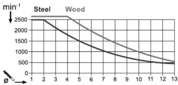
10.7 Setting the drilling speed (fig. 4)
The correct speed must be set to suit the workpiece to be drilled and the tool diameter.
10.7.1 Electronic speed control:
The speed of the individual gears can be seamlessly adjusted with the electronic speed control:
Set the speed with the help of the speed control (12.1/12.2).
The current speed can be seen on the display (9).
10.8 Switching on/off (fig. 1)
Make sure that the chuck guard (13) is folded down before switching on.
Switching on: Press the on switch (11) to switch the device on.
Switching off: Press the off switch (10) to switch the device off.
Attention: The speed set during the drilling process will be saved and will be kept until changed or the electric tool is disconnected from the mains. Once the electric tool is connected to the power supply again it will start up with a preset speed of 1500 rpm.
10.9 Drilling procedure (fig. 1)
- Align the workpiece and clamp it firmly in place as described in point 10.5.
- Start the device and set the speed, as described in point 10.7.
- For drilling, move the handle (8) with uniform feed until the desired drilling depth is reached. When drilling into metal, interrupt the downward pressure briefly to break the swarf.
- After reaching the drilling depth, return the handle (8) to the starting position.
- Switch the device off.
11. Transport
- To transport the device hold it by the base plate (1).
12. Cleaning and maintenance
Warning! Pull out the mains plug before carrying out any adjustments, maintenance or repair work!
12.1 General maintenance tasks
Wipe swarf and dust off the machine from time to time with a cloth. Oil the rotating parts once monthly to extend the life of the tool. Do not oil the motor.
Do not use corrosive agents for cleaning the plastic.
Have tasks that are not described in this operating manual, carried out by a specialist workshop. Use only original parts. Let the device cool down before all maintenance and cleaning tasks.
There is a risk of burn!
Before using the device each time, check the device for obvious defects such as worn or damaged parts, correct seating of screws or other parts. Replace damaged parts.
12.2 Cleaning
Do not use cleaning agents or solvents. Chemical substances could damage the plastic parts of the device. Never clean the device under running water.
- Clean the device thoroughly after each use.
- Clean the ventilation holes and the surface of the device with a soft brush or cloth.
- Remove swarf, dust and dirt with a vacuum cleaner if necessary.
- Lubricate the moving parts regularly.
12.3 Maintenance
Brush inspection (fig. 10)
Check the carbon brushes after the first 50 operating hours with a new machine, or when new brushes have been fitted. After carrying out the first check, repeat the check every 10 operating hours.
If the carbon is worn to a length of 6mm or if the spring or contact wire are burned or damaged, it is necessary to replace both brushes. If the brushes are found to be usable following removal, it is possible to reinstall them.
To service the carbon brushes, loosen the four Phillips screws (M) on the access panel (as shown in Figure 10) counter-clockwise and lift off the access panel.
Then remove the carbon brushes.
Replace the carbon brushes in the reverse order.
12.4 Replacing the chuck (fig. 4/10)
Warning! Pull out the mains plug!
Tools required (not included in the scope of delivery): 1x open-ended spanner 27mm
- Remove the insertion tool as described in 10.3.2.
- Tighten the clamping sleeve (E) firmly, by turning the chuck key clockwise.
- Hold the drill-chuck with one hand and turn the nut (H) clockwise with the open-ended spanner (27 mm).
- As soon as you have loosened the drill-chuck from the shaft, you can remove it.
- Fasten the new chuck in reverse order.
When replacing the chuck, use only chucks approved by the manufacturer.
Order number: 390 6814 001
12.5 Service information
With this product, it is necessary to note that the following parts are subject to natural or usage-related wear, or that the following parts are required as consumables.
Wear parts*: Carbon brushes, drill bit
- may not be included in the scope of supply!
13. Storage
Store the device and its accessories in a dark, dry and frost-free place that is inaccessible to children. The optimum storage temperature lies between 5 and 30^ .
Store the electric tool in its original packaging.
Cover the electrical tool in order to protect it from dust and moisture.
Store the operating manual with the electrical tool.
14. Electrical connection
The electrical motor installed is connected and ready for operation. The connection complies with the applicable VDE and DIN provisions. The customer's mains connection as well as the extension cable used must also comply with these regulations.
14.1 Important information
In the event of overloading, the motor will switch itself off After a cool-down period (time varies) the motor can be switched back on again.
14.2 Faulty power supply cables
The insulation on electrical connection cables is often damaged.
This may have the following causes:
- Pressure points, where connection cables are passed through windows or doors.
- Kinks where the connection cable has been improperly fastened or routed.
- Places where the connection cables have been cut due to being driven over.
Insulation damage due to being ripped out of the wall outlet. - Cracks due to the insulation ageing.
Such damaged electrical connection cables must not be used and are life-threatening due to the insulation damage.
Check the electrical connection cables for damage regularly. Ensure that the connection cables are disconnected from electrical power when checking for damage.
Electrical connection cables must comply with the applicable VDE and DIN provisions. Only use connection cables with the marking H05VV-F.
The printing of the type designation on the connection cable is mandatory.
If it is necessary to replace the connection cable, this must be done by the manufacturer or their representative to avoid safety hazards.
14.3 AC motor:
The mains voltage must be 220 - 240V 50Hz
- Extension cables up to 25m long must have a cross-section of 1.5mm^2
Connections and repairs of electrical equipment may only be carried out by an electrician.
Please provide the following information in the event of any enquiries:
- Type of current for the motor
- Engine data - type plate
15. Disposal and recycling
The device is supplied in packaging to avoid transport damages. This packaging is raw material and can thus be used again or can be reintegrated into the raw material cycle.
The device and its accessories are made of different materials, such as metals and plastics. Take defective components to special waste disposal sites.
Check with your specialist dealer or municipal administration!
Old devices must not be disposed of with household waste!
This symbol indicates that this product must not be disposed of together with domestic waste in compliance with the Directive (2012/19/EU) pertaining to waste electrical and electronic equipment (WEEE). This product must be disposed of at a designated collection point. This can occur, for example, by handing it in at an authorised collecting point for the recycling of waste electrical and electronic equipment. Improper handling of waste equipment may have negative consequences for the environment and human health due to potentially hazardous substances that are often contained in electrical and electronic equipment. By properly disposing of this product, you are also contributing to the effective use of natural resources. You can obtain information on collection points for waste equipment from your municipal administration, public waste disposal authority, an authorised body for the disposal of waste electrical and electronic equipment or your waste disposal company.
16. Troubleshooting
| Fault Possible cause Remedy | ||
| Device does not start | Motor, cable or plug defective, building circuit breaker tripped | Check power outlet, mains connection cable, mains plug. Have repair carried out by electrical specialist. Check building circuit breakers. |
| On/off switch (11/10) defective Repair by customer service department | ||
| Motor defective Repair by customer service department | ||
| Heavy vibrations | Base plate (1) not fastened in place. Secure | machine to a work bench or similar |
| Drill bit not clamped centrally Check drill bit in | chuck (14) | |
| Motor overheats easily | Overloading of the motor, insufficient cooling of the motor. | Avoid overloading the motor while drilling, remove dust from the motor in order to ensure optimal cooling of the motor. |
| Motor makes excessive noise | Coils damaged, motor defective. Have checked by customer service department | |
Table des matieres: Page:
CE - Declaration of Conformity
| 2014/29/EU | 2004/22/EC | 89/686/EC_96/58/EC | 2000/14/EC_2005/88/EC | ||
| 2014/35/EU | 2014/68/EU | 90/396/EC | Annex V | ||
| X | 2014/30/EU | X 2011/65/EU* | Annex VI Noise: measured LWA= xx dB(A); guaranteed LWA= xx dB(A) P = xx KW; L/Ø = cm Notified Body: Notified Body No.: | ||
| X 2006/42/EC | |||||
| Annex IV Notified Body: Notified Body No.: | 2010/26/EC | ||||
| Certificate No.: | Emission. No: | ||||
Standard references:
EN 62841-1:2015; EN 62841-3-13:2017; EN 60825-1-2014;
EN 55014-1:2017; EN55014-2:2015; EN 61000-3-2:2014; EN 61000-3-3:2013
This declaration of conformity is issued under the sole responsibility of the manufacturer.
The object of the declaration described above fulfils the regulations of the directive 2011/65/EU of the European Parliament and Council from 8th June 2011, on the restriction of the use of certain hazardous substances in electrical and electronic equipment.
Subject to change without notice
Documents registrar: Ann-Katrin Bloching
Günzburgr Str. 69, D-89335 Ichenhausen
Garantie DE
Apparent defects must be notified within 8 days from the receipt of the goods. Otherwise, the buyer's rights of claim due to such defects are invalidated. We guarantee for our machines in case of proper treatment for the time of the statutory warranty period from delivery in such a way that we replace any machine part free of charge which provably becomes unusable due to faulty material
or defects of fabrication within such period of time. With respect to parts not manufactured by us we only warrant insofar as we are entitled to warranty claims against the upstream suppliers. The costs for the installation of the new parts shall be borne by the buyer. The cancellation of sale or the reduction of purchase price as well as any other claims for damages shall be excluded.