HS200 - Saw SCHEPPACH - Free user manual and instructions
Find the device manual for free HS200 SCHEPPACH in PDF.


User questions about HS200 SCHEPPACH
0 question about this device. Answer the ones you know or ask your own.
Ask a new question about this device
Download the instructions for your Saw in PDF format for free! Find your manual HS200 - SCHEPPACH and take your electronic device back in hand. On this page are published all the documents necessary for the use of your device. HS200 by SCHEPPACH.
USER MANUAL HS200 SCHEPPACH
natural_image
Black and white photo of a machine with a saw cutting through a flat workbench, labeled 'schoppack' (no additional text or symbols visible)HS200
| DE | TischkreissägeOriginalbetriebsanleitung | 10 - 21 |
| GB | Table SawTranslation of Original Operating Manual | 22 - 33 |
| FR | Scie de tableTraduction de la notice originale | 34 - 45 |
| IT | Sega Cicolare da BancoTraduzioni del manuale d'uso originale | 46 - 57 |
| CZ | Stolová kotoučová pilaPřeklad originálního návodu k obsluze | 58 - 68 |
| SK | Stolová kotúčová pílaPreklad originálu návodu na obsluhu | 69 - 80 |
| HU | FúrészasztalAz eredeti használati útmutató fordítása | 81 - 91 |
DE

Nur für EU-Länder.
Only for EU countries.
Do not dispose of electric tools together with household waste material! In observance of European directive 2012/19/EU on wasted electrical and electronic equipment and its implementation in accordance with national law, electric tools that have reached the end of their life must be collected separately and returned to an environmentally compatible recycling facility
FR

natural_image
Technical line drawing of a metal ladder structure with support beams and a handle (no text or symbols)C

natural_image
Technical line drawing of a mechanical device with gears and a fan assembly (no text or symbols)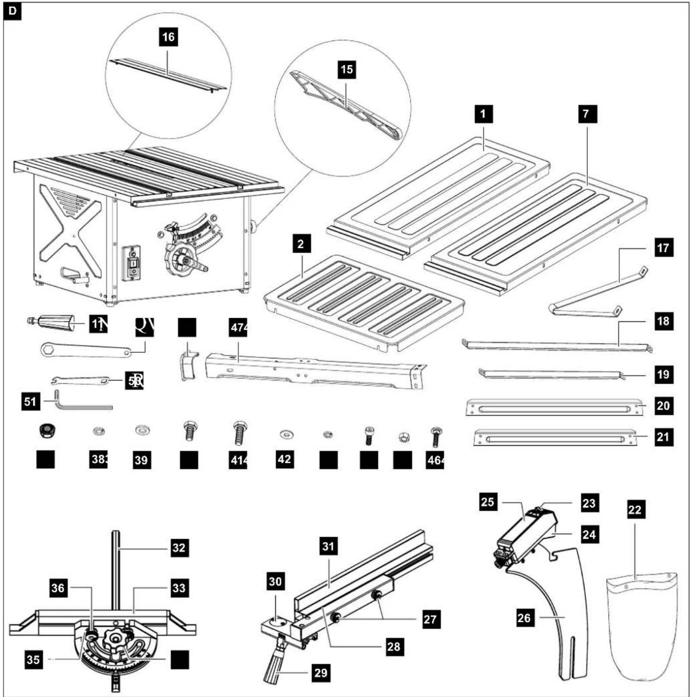
text_image
Exploded view diagram of a refrigerator assembly with numbered parts and exploded views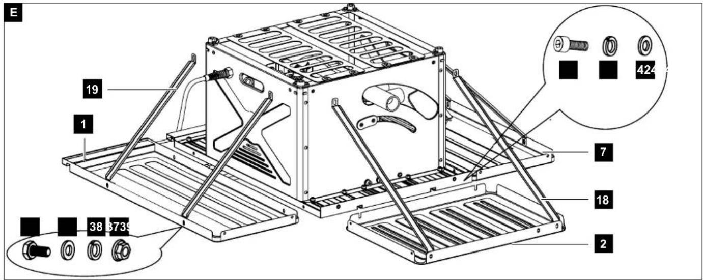
text_image
E 19 1 7 424 38 3739 18 2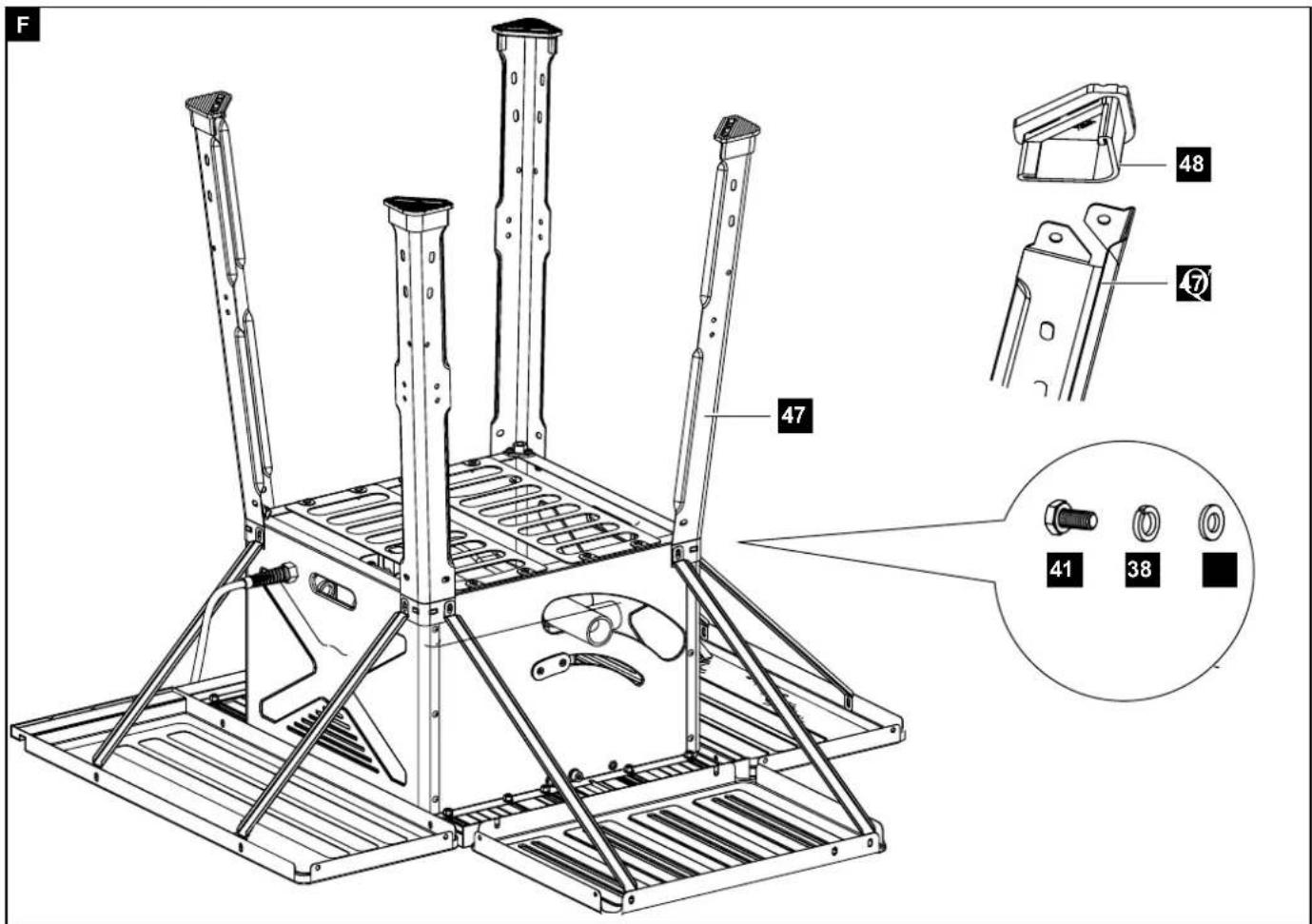
text_image
F 47 48 41 38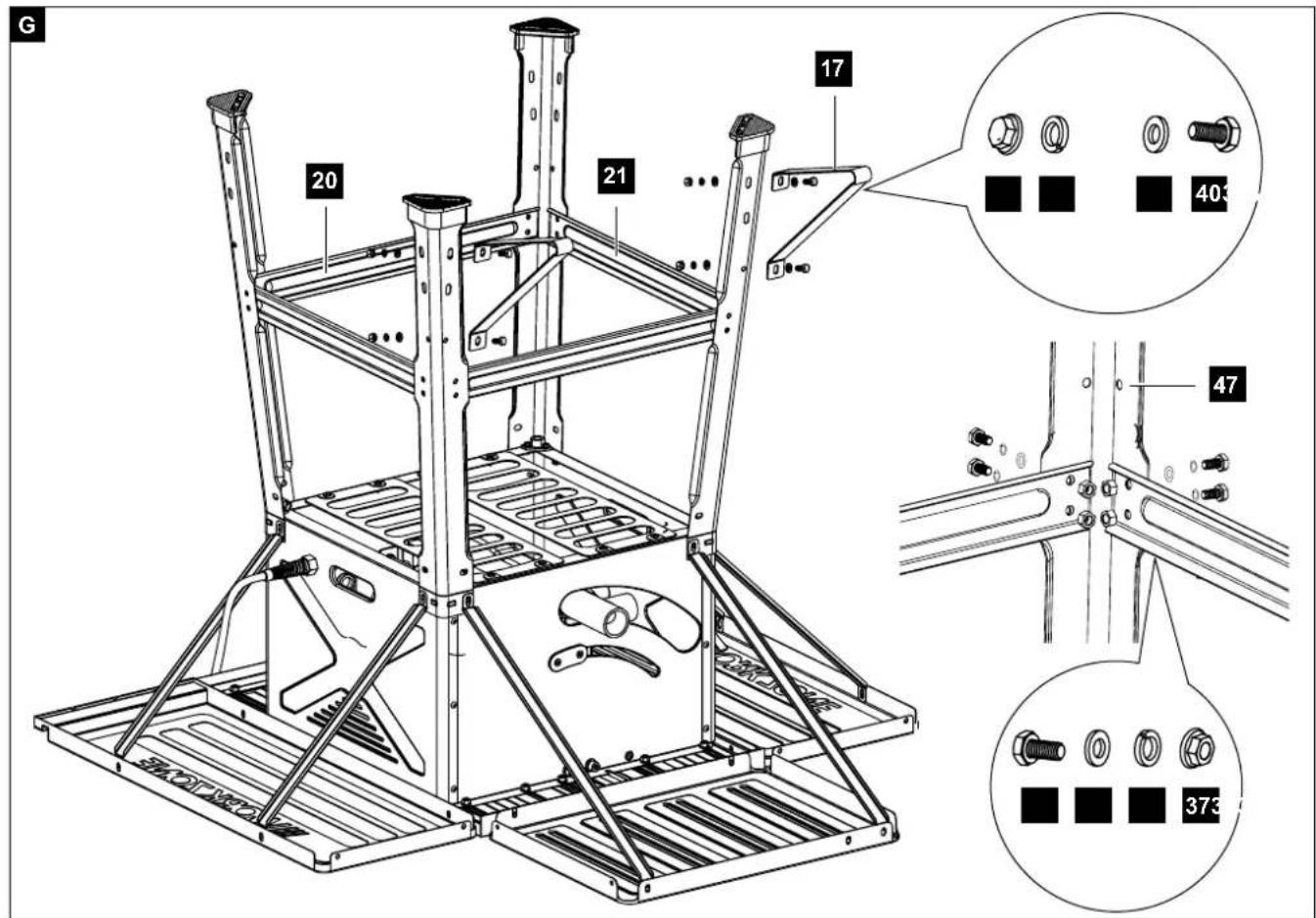
text_image
G 20 21 17 40 47 373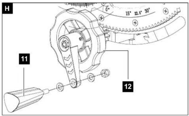
text_image
H 11 12 6° 15° 22.6° 30°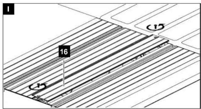
text_image
1 16 15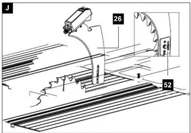
text_image
J 26 52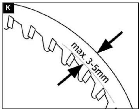
text_image
K max. 3-5mm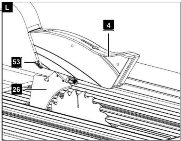
text_image
L 4 53 26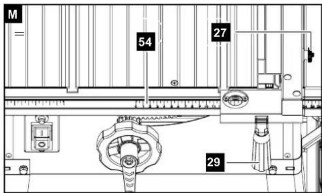
text_image
M = 54 27 160 29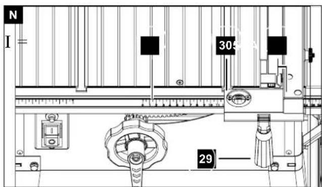
text_image
N I = 305 29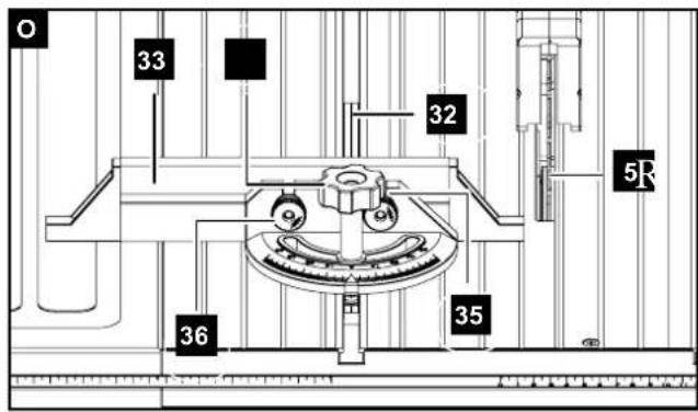
text_image
O 33 32 5R 36 35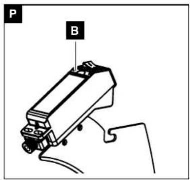
text_image
P B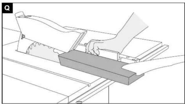
natural_image
Technical line drawing of a hand operating a workbench with a wooden block (no text or symbols)
text_image
R ä =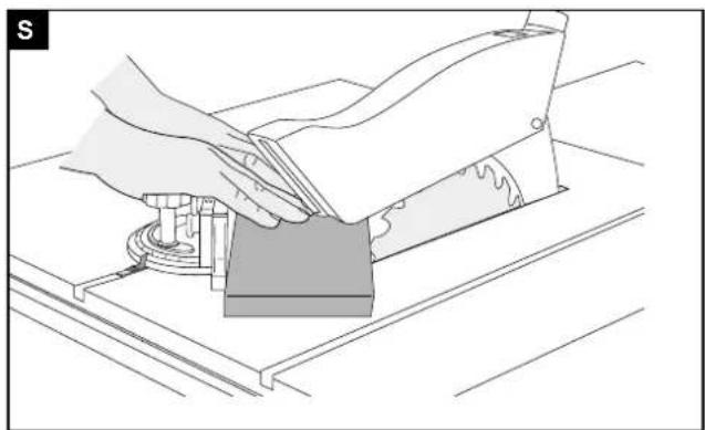
natural_image
Illustration of a hand using a tool to cut or spread a component on a workbench (no text or symbols visible)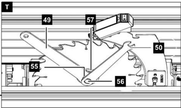
text_image
T 49 57 50 55 56Günzburger Straße 69
D-89335 Ichenhausen
VEREHRTER KUNDE,
Explanation of the symbols on the equipment
 | GB | Warning! Danger to life, risk of injury or damage to the tool are possible by ignoring!. |
 | GB | Caution - Read the operating instructions to reduce the risk of inquiry |
 | GB | Wear safety goggles! |
 | GB | Wear ear-muffs! |
 | GB | Wear a breathing mask! |
 | GB | Important! Risk of injury. Never reach into the running saw blade! |
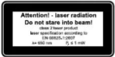
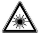 | GB | Important! Laser radiation |
 |
Introduction
MANUFACTURER:
scheppach
Günzburger Straße 69
D-89335 Ichenhausen
DEAR CUSTOMER,
We hope your new tool brings you much enjoyment and success.
NOTE:
According to the applicable product liability laws, the manufacturer of the device does not assume liability for damages to the product or damages caused by the product that occurs due to:
- Improper handling,
• Non-compliance of the operating instructions,
• Repairs by third parties, not by authorized service technicians.
• Installation and replacement of non-original spare parts.
• Application other than specified,
- A breakdown of the electrical system that occurs due to the non-compliance of the electric regulations and VDE regulations 0100, DIN 57113 / VDE0113.
WE RECOMMEND:
Read through the complete text in the operating instructions before installing and commissioning the device. The operating instructions are intended to help the user to become familiar with the machine and take advantage of its application possibilities in accordance with the recommendations. The operating instructions contain important information on how to operate the machine safely, professionally and economically, how to avoid danger, costly repairs, reduce downtimes and how to increase reliability and service life of the machine. In addition to the safety regulations in the operating instructions, you have to meet the applicable regulations that apply for the operation of the machine in your country. Keep the operating instructions package with the machine at all times and store it in a plastic cover to protect it from dirt and moisture. Read the instruction manual each time before operating the machine and carefully follow its information. The machine can only be operated by persons who were instructed concerning the operation of the machine and who are informed about the associated dangers. The minimum age requirement must be complied with. In addition to the safety requirements in these operating instructions and your country's applicable regulations, you should observe the generally recognized technical rules concerning the operation of woodworking machines.
Device Description (Fig .A-D)
-
Table width extension, left
-
Table length extension
-
Cross guide
-
Saw blade guard
-
Saw blade,
-
Parallel guide
-
Table width extension, right
-
Overload switch
-
Locking knob
-
Angle scale
-
Crank
-
Crank wheel
-
Operating switch (green I / red O)
-
Suction nozzles
-
Push stick
-
Table insert
-
Tip guard,
-
Table support, long,
-
Table support, short,
-
Dividing bar, long,
-
Dividing bar, short,
-
Cutting scraps sack (Depending on the scope of delivery)
-
Laser switch
-
Laser
-
Battery compartment cover
-
Splitting wedge
-
Knurled bolt (parallel guide),
-
Metal fixation tray with carriage bolts
-
Eccentric lever
-
Viewing window
-
Stop rail (parallel guide)
-
Guide rail
-
Stop rail (cross guide)
-
Knurled knob
-
Carriage bolt (cross guide),
-
Knurled bolt (cross guide),
-
Flange nuts M6,
-
Spring washers M6,
-
Ring washers M6
-
Hexagonal bolts M6×12,
-
Hexagonal bolts M6×16,
-
Ring washers M5,
-
Spring washers M5,
-
Hexagon socket bolts M5×14,
-
Nuts M5, 4×
-
Carriage bolts M5×14,
-
Support leg,
-
Rubber foot,
-
Ring spanner
-
Saw blade key
-
Hex key
Unpacking
- Open the packaging and remove the device carefully.
- Remove the packaging material as well as the packaging and transport bracing (if available).
- Check that the delivery is complete.
- Check the device and accessory parts for transport damage.
- If possible, store the packaging until the warranty period has expired.
ATTENTION
The device and packaging materials are not toys! Children must not be allowed to play with plastic bags, film and small parts! There is a risk of swallowing and suffocation!
Intended use
The bench-type circular saw is designed for the slitting and cross-cutting of all types of timber, commensurate with the machine's size.
The machine is not to be used for cutting any type of roundwood.
The machine is to be used only for its prescribed purpose. Any use other than that mentioned is considered to be a case of misuse. The user/operator and not the manufacturer shall be liable for any damage or injury resulting such cases of misuse.
The machine is to be operated only with suitable saw blades. It is prohibited to use any type of cutting-off wheel. To use the machine properly you must also observe the safety regulations, the assembly instructions and the operating instructions to be found in this manual. All persons who use and service the machine have to be acquainted with this manual and must be informed about its potential hazards. It is also imperative to observe the accident prevention regulations in force in your area. The same applies for the general rules of occupational health and safety.
⚠️ Important!
When using the equipment, a few safety precautions must be observed to avoid injuries and damage. Please read the complete operating instructions and safety regulations with due care. Keep this manual in a safe place, so that the information is available at all times. If you give the equipment to any other person, hand over these operating instructions and safety regulations as well. We cannot accept any liability for damage or accidents which arise due to a failure to follow these instructions and the safety instructions.
The manufacturer shall not be liable for any changes made to the machine nor for any damage resulting from such changes.
Even when the machine is used as prescribed it is still impossible to eliminate certain residual risk factors.
The following hazards may arise in connection with the machine's construction and design:
- Contact with the saw blade in the uncovered saw zone.
- Reaching into the running saw blade (cut injuries).
- Kick-back of workpieces and parts of workpieces
- Saw blade fracturing.
- Catapulting of faulty carbide tips from the saw blade.
- Damage to hearing if essential ear-muffs are not worn.
- Harmful emissions of wood dust when the machine is used in closed rooms.
m Please note that our equipment has not been designed for use in commercial, trade or industrial applications. Our warranty will be voided if the machine is used in commercial, trade or industrial businesses or for equivalent purposes.
Safety information
⚠ Attention! The following basic safety measures must be observed when using electric tools for protection against electric shock, and the risk of injury and fire. Read all these notices before using the electric tool and keep the safety instructions for later reference.
Safe work
1 Keep the work area orderly
Disorder in the work area can lead to accidents.
2 Take environmental influences into account
- Do not expose electric tools to rain.
-
Do not use electric tools in a damp or wet environment.
-
Make sure that the work area is well-illuminated.
- Do not use electric tools where there is a risk of fire or explosion.
3 Protect yourself from electric shock
- Avoid physical contact with earthed parts (e.g. pipes, radiators, electric ranges, cooling units).
4 Keep children away
- Do not allow other persons to touch the equipment or cable, keep them away from your work area.
5 Securely store unused electric tools
– Unused electric tools should be stored in a dry, elevated or closed location out of the reach of children.
6 Do not overload your electric tool
– They work better and more safely in the specified output range.
7 Use the correct electric tool
- Do not use low-output electric tools for heavy work.
- Do not use the electric tool for purposes for which it is not intended. For example, do not use hand-held circular saws for the cutting of branches or logs.
- Do not use the electric tool to cut firewood.
8 Wear suitable clothing
- Do not wear wide clothing or jewellery, which can become entangled in moving parts.
- When working outdoors, anti-slip footwear is recommended.
- Tie long hair back in a hair net.
9 Use protective equipment
- Wear protective goggles.
- Wear a mask when carrying out dust-creating work.
10 Connect the dust extraction device if you will be processing wood, materials similar to wood, or plastics.
- If connections for dust extraction and a collecting device are present, make sure that they are connected and used properly.
- When processing wood, materials similar to wood, and plastics. operation in enclosed spaces is only permitted with the use of a suitable extraction system.
11 Secure the workpiece
- Use the clamping devices or a vice to hold the workpiece in place. In this manner, it is held more securely than with your hand.
- An additional support is necessary for long workpieces (table, trestle, etc.) in order to prevent the machine from tipping over.
- Always press the workpiece firmly against the working plate and stop in order to prevent bouncing and twisting of the workpiece.
12 Avoid abnormal posture
- Make sure that you have secure footing and always maintain your balance.
- Avoid awkward hand positions in which a sudden slip could cause one or both hands to come into contact with the saw blade.
13 Take care of your tools
- Keep cutting tools sharp and clean in order to be able to work better and more safely.
– Follow the instructions for lubrication and for tool replacement. - Check the connection cable of the electric tool regularly and have it replaced by a recognised specialist when damaged.
- Check extension cables regularly and replace them when damaged.
- Keep the handle dry, clean and free of oil and grease.
14 Pull the plug out of the outlet
- Never remove loose splinters, chips or jammed
wood pieces from the running saw blade.
– During non-use of the electric tool or prior to maintenance and when replacing tools such as saw blades, bits, milling heads.
- When the saw blade is blocked due to abnormal feed force during cutting, turn the machine off and disconnect it from power supply. Remove the work piece and ensure that the saw blade runs free. Turn the machine on and start new cutting operation with reduced feed force.
15 Do not leave a tool key inserted
- Before switching on, make sure that keys and adjusting tools are removed.
16 Avoid inadvertent starting
- Make sure that the switch is switched off when plugging the plug into an outlet.
17 Use extension cables for outdoors
- Only use approved and appropriately identified extension cables for use outdoors. - Only use cable reels in the unrolled state.
18 Remain attentive
– Pay attention to what you are doing. Remain sensible when working. Do not use the electric tool when you are distracted.
19 Check the electric tool for potential damage
- Protective devices and other parts must be carefully inspected to ensure that they are fault-free and function as intended prior to continued use of the electric tool.
- Check whether the moving parts function faultlessly and do not jam or whether parts are damaged. All parts must be correctly mounted and all conditions must be fulfilled to ensure fault-free operation of the electric tool.
- The moving protective hood may not be fixed in the open position.
- Damaged protective devices and parts must be properly repaired or replaced by a recognised workshop, insofar as nothing different is specified in the operating manual.
- Damaged switches must be replaced at a customer service workshop.
- Do not use any faulty or damaged connection cables.
- Do not use any electric tool on which the switch cannot be switched on and off.
20 ATTENTION!
– Exercise elevated caution for double mitre cuts.
21 ATTENTION!
- The use of other insertion tools and other accessories can entail a risk of injury.
22 Have your electric tool repaired by a qualified electrician
- This electric tool conforms to the applicable safety regulations. Repairs may only be performed by an electrician using original spare parts. Otherwise accidents can occur.
23 Do not use the cable for purposes for which it is not intended
- Do not use the cable to pull the plug out of the outlet. Protect the cable from heat, oil and sharp edges.
ADDITIONAL SAFETY INSTRUCTIONS
1 Safety precautions
- Warning! Do not use damaged, cracked or deformed saw blades.
- Replace a worn table insert.
- Only use saw blades recommended by the manufacturer which conform to EN 847-1.
⚠ Warning! Keep attention When changing the saw blade. The cutting width is not smaller and
the main blade thickness of the saw blade is not greater than the thickness of the gap wedge!
- Make sure that a suitable saw blade for the material to be cut is selected.
- Wear suitable personal protective equipment. This includes:
Hearing protection to avoid the risk of becoming hearing impaired,
Respiratory protection to avoid the risk of inhaling harmful dust,
- Wear gloves when handling saw blades and rough materials.
- Carry saw blades in a container whenever practical.
- Wear goggles. Sparks generated during work or splinters, chippings and dust coming from the device can lead to loss of eyesight.
- Connect a dust collecting device to the electric tool when sawing wood. The emission of dust is influenced, among other things, by the type of material to be processed, the significance of local separation (collection or source) and the correct setting of the hood/guide plates/guides.
- Do not use saw blades made of high-speed alloy steel (HSS steel).
- In times of non-use keep the push stick or the push block with the electrical power tool in its holder at all times.
2 Maintenance and repair
– Pull out the mains plug for any adjustment or repair tasks.
- The generation of noise is influenced by various factors, including the characteristics of saw blades, condition of saw blade and electric tool. Use saw blades which were designed for reduced noise development, insofar as possible. Maintain the electric tool and tool attachments regularly and if necessary, initiate repairs in order to reduce noise.
- Report faults on the electric tool, protective devices or the tool attachment to the person responsible for safety as soon as they are discovered.
3 Safe work
- Use the push stick or handle with sliding wood, to pass the workpiece securely out off the saw blade.
- Make sure that the riving knife is always used, and set up is correctly.
- Use the upper blade guard and set it to the correct position.
- Only use saw blades for which the maximum permissible speed is not lower than the maximum spindle speed of table saws and which are suitable for the material to be cut.
- Do not cut rebates or grooves without fitting a suitable guard, e.g. a tunnel-type guard, over the saw table.
- Circular saws must not be used for slotting jobs (cutting grooves which end in the workpiece).
- When transporting the electric tool, only use the transport devices. Never use the protective devices for handling or transport.
- Make sure that the upper part of the saw blade is covered during transport, e.g. by the protective device.
- Be sure to only use spacers and spindle rings specified by the manufacturer as suitable for the intended purpose.
- The floor around the machine must be level, clean and free of loose particles, such as chips
and cutting residues.
- Always stand to the side of the saw blade when working with the saw.
- Do not remove any cutting residues or other parts of workpieces from the cutting zone while the machine is running and the saw unit is not at rest.
- Make sure that the machine is always secured on a workbench or a table if at all possible.
- Support long workpieces (e.g. with a roller table) to prevent them sagging at the end of a cut.
- ⚠ Attention! Never remove loose splinters, chips or jammed pieces of wood while the saw blade is running.
- Switch off the machine to troubleshoot or remove jammed pieces of wood. - Disconnect the main power plug -
- Refitting, including adjusting and measuring works, and cleaning must be carried out only when the motor is switched off. - Disconnect the main power plug -
- Before switching on again, ensure that keys and adjustment tools have been removed.
Warning! This electric tool generates an electromagnetic field during operation. This field can impair active or passive medical implants under certain conditions. In order to prevent the risk of serious or deadly injuries, we recommend that persons with medical implants consult with their physician and the manufacturer of the medical implant prior to operating the electric tool.
SAFETY INSTRUCTIONS FOR THE HANDLING OF SAW BLADES
1 Only use insertion tools if you have mastered their use.
2 Observe the maximum speed. The maximum speed specified on the insertion tool may not be exceeded. If specified, observe the speed range.
3 Observe the motor / saw blade direction of rotation.
4 Do not use any insertion tools with cracks. Sort out cracked insertion tools. Repairs are not permitted.
5 Clean grease, oil and water off of the clamping surfaces.
6 Do not use any loose reducing rings or bushes for the reducing of holes on saw blades.
7 Make sure that fixed reducer rings for securing the insertion tool have the same diameter and have at least 1/3 of the cutting diameter.
8 Make sure that fixed reducer rings are parallel to each other.
9 Handle insertion tool with caution. They are ideally stored in the originally package or special containers. Wear protective gloves in order to improve grip and to further reduce the risk of injury.
10 Prior to the use of insertion tools, make sure that all protective devices are properly fastened.
11 Prior to use, make sure that the insertion tool meets the technical requirements of this electric tool and is properly fastened.
12 Only use the supplied saw blade for sawing operations in wood, materials similar to wood, plastics and non-ferrous metals (except for magnesium and alloys containing magnesium).

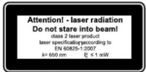
Attention: Laser radiation Do not stare into the beam Class 2 laser
text_image
Attention! - laser radiation Do not stare into beam! class 2 laser product laser specification according to EN 60825-1:2007 λ= 650 nm f₀ ≤ 1 mWProtect yourself and you environment from accidents using suitable precautionary measures!
- Do not look directly into the laser beam with unprotected eyes.
- Never look into the path of the beam.
- Never point the laser beam towards reflecting surfaces and persons or animals. Even a laser beam with a low output can cause damage to the eyes.
- Caution - methods other than those specified here can result in dangerous radiation exposure.
- Never open the laser module. Unexpected exposure to the beam can occur.
- If the mitre saw is not used for an extended period of time, the batteries should be removed.
- The laser may not be replaced with a different type of laser.
- Repairs of the laser may only be carried out by the laser manufacturer or an authorised representative.
Safety instructions for handling batteries
1 Always make sure that the batteries are inserted with the correct polarity (+ and −), as indicated on the battery.
2 Do not short-circuit batteries.
3 Do not charge non-rechargeable batteries.
4 Do not overcharge batteries!
5 Do not mix old and new batteries or batteries of different types or manufacturers! Replace an entire set of batteries at the same time.
6 Immediately remove used batteries from the device and dispose of them properly!
7 Do not allow batteries to heat up!
8 Do not weld or solder directly on batteries!
9 Do not dismantle batteries!
10 Do not allow batteries to deform!
11 Do not throw batteries into fire!
12 Keep batteries out of the reach of children.
13 Do not allow children to replace batteries without supervision!
14 Do not keep batteries near fire, ovens or other sources of heat. Do not use batteries in direct sunlight or store them in vehicles in hot weather.
15 Keep unused batteries in the original packaging and keep them away from metal objects. Do not mix unpacked batteries or toss them together! This can lead to a short-circuit of the battery and thus damage, burns or even the risk of fire.
16 Remove batteries from the equipment when it will not be used for an extended period of time, unless it is for emergencies!
17 NEVER handle batteries that have leaked without appropriate protection. If the leaked fluid comes into contact with your skin, the skin in this area should be
rinsed off under running water immediately. Always prevent the fluid from coming into contact with the eyes and mouth. In the event of contact, please seek immediate medical attention.
18 Clean the battery contacts and corresponding contacts in the device prior to inserting the batteries:
Residual risks
The machine has been built according to the state of the art and the recognised technical safety requirements. However, individual residual risks can arise during operation.
- Health hazard due to electrical power, with the use of improper electrical connection cables.
• Furthermore, despite all precautions having been met, some non-obvious residual risks may still remain. - Residual risks can be minimised if the „safety instructions“ and the „Proper use“ are observed along with the whole of the operating instructions.
- Do not load the machine unnecessarily: excessive pressure when sawing will quickly damage the saw blade, which results in reduced output of the machine in the processing and in cut precision.
- When cutting plastic material, please always use clamps: the parts which should be cut must always be fixed between the clamps.
- Avoid accidental starting of the machine: the operating button may not be pressed when inserting the plug in an outlet.
- Use the tool that is recommended in this manual. In doing so, your saw provides optimal performance.
- Hands may never enter the processing zone when the machine is in operation. Release the handle button and switch off the machine prior to any operations.
- Prior to any adjustment, maintenance or service work disconnect the mains power plug!
Technical Data
| AC motor 230-240 V~ 50Hz | |
| performance 2000 Watt | |
| operating mode S6 40% (5 min.)* | |
| Idle speed 4200 min | -1 |
| Hard-metal blade | ø 250 x ø 30 x 2,4 mm |
| Number of teeth | 24 |
| Thickness riving knife | 2 mm |
| table size | 610 x 445 mm |
| Cutting height max. 90° | 73 mm |
| Cutting height max. 45° | 53 mm |
| height adjustment | 0 - 73 mm |
| saw blade swivel | 0 - 45° |
| suction port | ø 35 mm |
| weight | 24,5 kg |
| Laser class | 2 |
| Wavelength of laser | 650 nm |
| Laser output | ≤ 1 mW |
| Laser module power supply | 2x1,5V; AAA/LR03 |
* operating mode S6 40%: Continuous operation with intermittent loading (playing time 5 min).
Engine protection of to hot warming up:
It's allowed to run the engine with nominal power maximum
40% of playing time. After this the machine must run 60% of playing time steadily without load.
Noise values
The total noise values determined in accordance with EN 61029.
| sound pressure level L_pA | 96,2 dB(A) |
| uncertainty K_pA | 3 dB |
| sound power level L_WA | 109,2B(A) |
| uncertainty K_WA | 3 dB |
Wear hearing protection.
The effects of noise can cause a loss of hearing. Total vibration values (vector sum - three directions) determined in accordance with EN 61029.
Before starting the equipment
- The equipment must be set up where it can stand securely.
- All covers and safety devices have to be properly fitted before the equipment is switched on.
- It must be possible for the blade to run freely.
- When working with wood that has been processed before, watch out for foreign bodies such as nails or screws, etc.
- Before you press the ON/OFF switch check that the saw blade is fitted correctly. Moving parts must run smoothly.
- Before you connect the equipment to the power supply make sure the data on the rating plate are dentical to the mains data.
- Connect the machine to a properly installed protective contact socket, with at least 16A circuit breaker.
Assembly
⚠ Warning! Risk of injury!
Incorrectly assembling the table saw can result in serious injury.
- Before start-up, assemble the table saw properly and completely, including all covers and safety devices.
- Do not in any case insert the mains plug in the socket until you have completed assembly.
If connections need to be secured with a hex bolt, nut, spring washer or ring washer, the ring washer and spring washer must be positioned underneath the hex bolt. The spring washer should always lie directly upon the (socket) hexagonal bolt or nut. The spring washer must be positioned first, then the ring washer. Hexagon bolts must always be inserted from outside to the inside and the nut connections must be secured from the inside. Nuts and bolts must only be screwed in during installation until they are hand-tight so that they cannot fall out. If you secure the nuts and bolts completely before the final installation, the table saw cannot be correctly and stably positioned.
Mounting table width and length extensions
- Turn the saw table over and place it on the floor (see Fig. E).
- Install both table width extensions (1 / 7) loosely onto the table saw using a total of four M6×12 hexagonal bolts (40), four M6 spring washers (38), four M6 ring washers (39) and four M6 flange nuts (37). Use the corresponding drill holes on the saw table for this.
- Install the table length extension (2) loosely onto the table saw with a total of two M5×14 hexagon socket
bolts (44), two M5 spring washers (43) and two M5 ring washers (42) using the hex key (51). Use the corresponding threaded drill holes on the table saw for this.
- Mount the four short table supports (19) loosely on the two table width extensions using four M6×12 hexagonal bolts, four M6 spring washers, four M6 ring washers and four M6 flange nuts.
- Mount the two long table supports (18) loosely onto the table length extension with two M6×12 hexagonal bolts, two M6 spring washers, two M6 ring washers and two M6 flange nuts.
- Align the table width extensions and the table length extension so that they are level with the saw table and tighten all existing screwed connections.
Assembling the frame
- Place one rubber foot (48) on each of the support legs (47) (see Fig. F).
- Mount the four support legs and the free ends of the table supports (18 / 19) onto the table saw using eight M6×16 hexagonal bolts (41), eight M6 spring washers (38) and eight M6 ring washers (39). Use the corresponding threaded drill holes on the table saw for this.
- Position one long dividing bar (20) between each of the two support legs on the front side (crank wheel 12) and on the rear side (suction nozzles 14) of the table saw (see Fig. G).
- Fasten both long dividing bars to the support legs with eight M6×12 hex bolts (40), eight M6 spring washers, eight M6 ring washers and eight M6 flange nuts.
- Position one short dividing bar (21) each between two support legs and fasten them using eight M6×12 hex bolts, eight M6 spring washers, eight M6 ring washers and eight M6 flange nuts to the support legs.
- Now tighten all existing connections.
- Mount a tip guard (17) on each of the support legs on the reverse side with four M6×12 hex bolts, four M6 spring washers, four M6 ring washers and four M6 flange nuts (see Fig. G).
- Carefully turn the saw table over and set it upright with its support legs on the ground.
Affix the hand crank (Fig. H)
- Mount the crank (11) with the ring washers you have already affixed and the lock nuts to the crank wheel (12) in such a way that the crank will still turn.
Mounting/adjusting the splitting wedge (Fig. I / J / K) ⚠ WARNING! Risk of injury!
Unintended activation of the table saw and improper handling of the saw blade could result in serious injury.
- Always pull the mains plug out of the socket before you make any adjustments to the table saw's settings.
• Always wear protective gloves when handling the saw blade or working in its direct vicinity.
Check the splitting wedge (26) every time after you change the saw blade and realign it if necessary.
- Make sure that the saw blade (5) has been lowered all the way into the saw table. If necessary, lower the saw blade by turning the crank (11) counterclockwise up to the stop point.
- Where appropriate, remove the saw blade guard (4) from the splitting wedge by loosening the lens head
screw (53), pulling the saw blade protection gently apart and then carefully withdrawing it over the laser (24) from the splitting wedge (see chapter "Mounting/dismantling the saw blade guard").
- Loosen the two fixing bolts and remove the table insert (16) from the saw table. Always check the table insert in the process: Immediately replace the table insert if it is damaged or is no longer flush with the saw table.
- Make sure that the angle of the saw blade is set to 0^ . If necessary, set the angle (see chapter "Setting the cutting angle").
- Rotate the saw blade all the way out of the saw table by turning the crank clockwise up to the stop point.
- Loosen the clamping nut on the clamping plate (52) with the ring spanner (SW 10) (49) by a few turns in an anti-clockwise direction.
- Insert the splitting wedge (26) behind the clamping plate and push it all the way down.
- Gently screw the clamp bolt tight in a clockwise direction.
- Align the splitting wedge so that there is 3–5 mm of space to the saw blade on all sides.
- Fix the splitting wedge in place by tightening the clamp bolt by turning it clockwise again.
- Turn the saw blade all the way into the saw table by turning the crank counterclockwise up to the stop point.
- Reinsert the table insert back into the saw table by inclining it to one side and clamping it into the saw table on the side furthest away from the saw blade.
- Now press the table insert down to the side nearest the saw blade so that it is level with the saw table.
- Fasten the table insert with both fixing bolts.
- Mount the saw blade guard (see chapter "Mounting/dismantling the saw blade guard").
Inserting/changing the batteries of the laser
You will need two type AAA/LR03 1.5 V batteries to operate the laser (24) (included in the package contents). Proceed as follows to insert or change them:
- Set the laser switch (23) to position 0.
- Remove the saw blade guard (4) from the splitting wedge (26) by loosening the lens head screw (53), gently pulling the saw blade guard apart and then carefully pulling it over the laser and off the splitting wedge.
- Loosen both bolts in the battery compartment cover (25), open up the battery compartment cover and remove it.
- Remove the old batteries from the battery compartment if necessary. Please observe the notes in the chapter "Disposal".
- Insert the new batteries. Make sure the polarity is correct in accordance with the instructions given in the battery compartment.
- Put the battery compartment cover back into place.
- Fasten the battery compartment cover with both screws.
- Mount the saw blade guard (see chapter "Mounting/dismantling the saw blade guard").
Mounting/dismantling the saw blade guard (Fig. L)
The batteries for the laser (24) must be inserted prior to the first assembly.
- Unscrew the lens head screw (53)
- Pull the saw blade guard (4) slightly apart and care-
fully guide it over the laser and onto the splitting wedge (26).
- Position the saw blade guard in such a way that the lens head screw reaches the nut in the splitting wedge.
- Fasten the saw blade guard to the splitting wedge using the lens head screw.
- Make sure that you do not overtighten the lens head screw; it should be easy to lift the saw blade guard up and down.
Mounting the parallel guide (Fig. M)
- Push the stop rail (31) onto the parallel guide (6) in such a way that the metal fixation tray with carriage bolts (28) slides into the guide groove of the stop rail.
- Fasten the stop rail on the parallel guide by tightening the two knurled bolts (27).
- Place the parallel guide with the opened eccentric lever (29) on the rail (54) on the saw table.
- In order to change the position of the parallel guide, push the parallel guide with the opened eccentric lever along the rail.
- In order to fasten the parallel guide in the required position, push the eccentric lever all the way down to lock it.
Mounting the cutting scraps sack (Depending on the scope of delivery)
The cutting scraps sack (22) is designed to collect smaller cut-off scraps.
- Hook the eyelets on the cutting scraps sack in the four pre-mounted carriage bolts M5×14 (46) (secured with four M5 nuts 45) in the left table width extension (1) and the table length extension (2) in such a way that the cutting scraps sack hangs securely.
Connecting the extraction device
A normal household vacuum cleaner is not a suitable extraction device.
- Place the tube which runs from the saw blade guard (4) onto the angle connection on the suction nozzles (14).
- Connect the suction hose to a suitable shavings extractor (e.g. a multi-purpose vacuum cleaner) to the suction nozzles and secure it with a hose clamp.
Setup
Setting the cutting depth
Using the crank (11), rotate the saw blade (5) out of the saw table or lower the saw blade into the table saw. In this way, you can set the desired cutting depth.
- Increase the cutting depth: Turn the crank clockwise so that the saw blade is drawn out of the table saw.
- Reduce the cutting depth: Turn the crank counter clockwise so that the saw blade is lowered into the table saw.
Setting the cutting angle
- Loosen the locking bolt (9) by approx. one rotation in an anti-clockwise direction.
- Use the crank wheel (12) to set the desired cutting angle on the angle scale (10).
- To fasten the saw blade (5) at the required angle, tighten the locking bolts by turning them clockwise.
Setting the parallel guide
The stop rail (31) for mounting on the parallel guide (6) has two guide surfaces of different heights. Depending on the thickness of the materials to be cut, turn the stop rail into an upright position for thick material (workpiece thickness over 25 mm) and into a flat position for thin material (workpiece thickness under 25 mm).
Setting the stop length
- Loosen the knurled bolts (27).
- Pull the stop rail off of the parallel guide. The metal fixation tray and the nuts will become visible.
- Turn the stop rail to the desired position (flat or upright).
- Push the metal fixation tray with carriage bolts (28) into the guide groove of the stop rails.
Change the side of the parallel guide
- Fully loosen the knurled bolts (27).
- Remove the stop rail with the metal fixation tray and the carriage bolts (28) and replace the bolts on the other side of the parallel guide.
- Fasten the stop rail on the parallel guide by tightening the two knurled bolts and the accompanying ring washers.
- Push the metal fixation tray with the bolts into the guide groove of the stop rail.
- Tighten the knurled bolts again in order to fasten the stop rail to the parallel guide.
Setting the cutting width (Fig. N)
When cutting wood pieces into lengths, the parallel guide should be installed on the right-hand side of the saw blade.
On the front of the saw table, on the rail (54), there are two scales. One is in red print and the other in black print and they display the distance between the stop rail and the saw blade (cutting width):
- Use the top scale in red print if you have installed the stop rail in a flat position (for thin material).
-
Use the lower scale in black print if you have mounted the stop rail in an upright position (for thick material). Proceed as follows to set the parallel guide to a certain dimension:
-
Lift the eccentric lever (29).
- Push the parallel guide until the desired dimension is visible on the scale on the rail (54) in the viewing window (30).
- Push the eccentric lever all the way down to lock it.
Setting the stop length
In order to avoid clamping the workpiece, the stop rail can be moved lengthwise.
The following rule applies: The back end of the stop runs into an imaginary line that roughly starts from the middle of the saw blade and runs to the back under 45^ .
- Set the required cutting width.
- Loosen the knurled bolts (27).
- Push the stop rail until its back end touches the imaginary 45^ line.
- Tighten the knurled bolts again.
Adjust the parallel guide
If the parallel guide with the stop rail is not parallel to the saw blade (5), it must be readjusted. Proceed as follows to do so:
-
Remove the saw blade guard (4).
-
Set the saw blade to the maximum cutting depth.
- Push the parallel guide in such a way that the stop rail touches the saw blade.
- If the stop rail does not run parallel with the saw blade, loosen the hexagon socket bolts A in the parallel guide using a 5 mm hex key (not included in the package contents) and orientate the stop rail in a parallel direction to the saw blade.
- Tighten the socket hex bolts again.
- Reposition the parallel guide away from the saw blade.
Setting the cross guide (Fig. O)
Do not push the stop rail (33) too far towards the saw blade 5.
There should be approx. 2 cm of space between the stop rail and saw blade.
- Push the stop rail (33) onto the cross guide (3) so that the two carriage bolts 35 slide into the profile of the stop rail.
- Fasten the stop rail to the cross guide by tightening the two knurled bolts (36).
- Push the guide rail (32) into one of the two guide slots on the saw table.
- Loosen the knurled nut (34) and turn the cross guide until you have set it at the required angle.
- Tighten the knurled bolt again.
Activating/deactivating the laser
With the help of the laser (24) you can perform precision cuts with the table saw.
Observe the safety instructions for the laser. The laser beam is produced using a laser diode. A line is produced which you can use as an optical mark for the cutting line when precision cutting. The laser switch (23) can be accessed through the opening on the top side if the saw blade guard 4 is mounted.
- To switch the laser on, set the laser switch to position I (laser on). A red laser beam will now be emitted out of the laser light opening. Keeping the laser beam along the cutting line mark while sawing will ensure that your cuts are neat.
- To switch the laser off, set the laser switch to position 0 (laser off). The laser beam will go out.
- To save the battery power, always switch the laser off when it is no longer needed.
Dust and chips that have accumulated may block the laser beam. These particles must therefore be removed from the saw blade guard after every use.
Adjusting the laser (Fig. P)
If the laser (24) no longer displays the correct cutting line, it can be subsequently adjusted.
- Loosen the screws (B) on the illuminating diode and position the laser in the required direction by pushing it in such a way that the laser beam meets the cutting teeth of the saw blade.
- Then tighten the screws again.
Operation
⚠ WARNING! Risk of injury!
Improper assembly of the table saw can result in serious injury.
- Before start-up, assemble the table saw properly and completely.
- Before switching the table saw on, make sure the saw blade is correctly mounted and that mobile parts can
move freely.
After switching on the saw, you must wait until the saw blade 5 has reached the maximum speed before you perform the cut.
Switching the table saw on and off
- To switch on the table saw, press the green operating switch I (13). The motor will start.
- To switch the table saw off, push the red operating switch 0.
Sawing with the table saw
⚠ WARNING! Risk of injury!
Improperly handling the table saw poses a risk of serious injury.
- When performing lengthwise cuts, do not stand directly in front of the table saw, instead stand diagonal to the cutting line.
- When performing bevel cuts, always use the parallel guide.
- Use a push stick or a push block to safely push the workpiece by the saw blade. Immediately replace a damaged or worn push stick.
- Secure long workpieces so that they do not tip over at the end of the cut. Use a roller stand for this, for example.
- After switching on the table saw, wait until the saw blade has reached its maximum speed before you perform the cut.
- Only operate the table saw with an extraction device.
• Each time after making a new setting, perform a test cut to check the set dimensions. - Check and clean the suction channels regularly.
Performing lengthwise cuts (Fig. Q)
A lengthwise cut is applied to cut a workpiece length-wise. Push an edge of the workpiece against the parallel guide (6) with the flat side on the saw table.
- Adjust the parallel guide to the workpiece height and the desired width (see chapter "Setting the parallel guide").
- Lower the saw blade guard (4) onto the saw table. The saw blade guard is pushed up by the workpiece while sawing.
- Switch on the dust extractor first and then the table saw.
- With your fingers closed, place your hands flat on the workpiece and push it along the parallel guide into the saw blade (5).
- Guide the workpiece laterally just to the front edge of the saw blade guard with your left hand.
- Always push the workpiece up to the end of the splitting wedge (26) using the push stick (15).
Performing bevel cuts (Fig. R)
- Set the saw blade to the desired angle (see chapter "Setting the cutting angle").
- Set the parallel guide corresponding to the width and height of the workpiece (see chapter "Setting the parallel guide").
- Lower the saw blade guard (4) onto the saw table.
- Perform the cut corresponding to the width of the workpiece (see chapter "Performing lengthwise cuts").
Performing cross cuts (Fig. S)
⚠ WARNING! Risk of injury!
Improperly handling the table saw poses a risk of serious injury.
- Always take hold of the guided workpiece and never of the unguided work piece that is being cut off.
- Always push the cross guide forward until the workpiece has been cut through completely.
- Set the cross guide (3) as necessary (see chapter "Setting the cross guide"). If the saw blade is also to be set at an angle, push the cross guide into the right-hand guide groove to prevent your hand and the cross guide from coming into contact with the saw blade guard.
- Lower the saw blade guard onto the saw table. The saw blade guard is pushed up by the workpiece while sawing.
- Firmly push the workpiece against the cross guide.
- Switch on the dust extractor first and then the table saw.
- To perform a cut, push the cross guide and the workpiece in the direction of the saw blade.
Cutting narrow workpieces
Be absolutely sure to use the push stick (15) when performing lengthwise cuts for workpieces with a width of under 120 mm. For shorter workpieces, the push stick must be used at the beginning of the cutting process.
- Adjust the parallel guide to the workpiece height and the desired width (see chapter "Setting the parallel guide").
- With your fingers closed, place your hands flat on the workpiece and push it along the parallel guide into the saw blade (5).
- Always push the workpiece up to the end of the splitting wedge (26) using the push stick.
For lengthwise cuts to very narrow workpieces with a width of 30 mm or less, a push block must be used (not included in the package contents). The parallel guide must be mounted flat.
- Adjust the parallel guide to the workpiece height and the desired width (see chapter "Setting the parallel guide").
- Push the workpiece with the push block against the stop rail and push the workpiece to the end of the splitting wedge using the push stick.
Always replace cracked push blocks on a timely basis.
Cutting particle boards
- To prevent raw edges when cutting particle boards, do not set the saw blade higher than 5 mm above the workpiece thickness.
When you are finished cutting
- First turn the table saw off and then the dust extractor. The saw blade will continue to rotate for some time.
- Remove the cutting waste from the saw blade when the saw blade returns to the resting position.
- Disconnect the table saw from the power supply by pulling the mains plug out of the socket.
- Let the table saw cool off completely.
Releasing the overload protection
This table saw is equipped with overload protection. If the motor has overloaded, the overload switch automatically deactivates it to protect the table saw from
overheating.
- If the overload protection has been activated, switch the table saw off by pressing the red operating switch 0 (13).
- Wait until the engine has cooled down.
- Press the overload switch (8) and switch the table saw on again by pressing the green operating switch I (13).
Removing jammed material
⚠ WARNING! Risk of injury!
Incorrect handling of the table saw poses a risk of serious injury.
- Immediately switch the table saw off and pull the mains plug out of the socket if the saw blade catches in the workpiece or any other blockages occur.
- Use protective gloves. Do not touch the saw blade with your bare hands.
Changing the saw blade (Fig. T)
⚠ WARNING! Risk of injury!
Incorrect handling of the table saw poses a risk of serious injury.
- Ensure that the table saw is not connected to the mains supply.
-
Use protective gloves. Do not touch the saw blade with your bare hands.
-
Make sure that the saw blade (5) has been lowered all the way into the saw table. If necessary, lower the saw blade by turning the crank (11) counterclockwise up to the stop point.
- Remove the saw blade guard (4) from the splitting wedge (26) by loosening the lens head screw (53), gently pulling the saw blade guard apart and then carefully pulling it over the laser (24) and off of the splitting wedge.
- Loosen the two fixing screws and remove the table insert (16) from the saw table. Always check the table insert in the process: Immediately replace the table insert if it is damaged or is no longer flush with the saw table.
- Make sure that the angle of the saw blade is set to 0^ . If necessary, set the angle (see chapter “Setting the cutting angle”).
- Rotate the saw blade all the way out of the saw table by turning the crank clockwise up to the stop point.
- Remove the splitting wedge by loosening the clamp bolt in the clamping plate (52) by turning it clockwise a few revolutions and then pulling the splitting wedge up and out.
- Attach the saw blade key (50) to the fixing nut (55).
- Fasten the drive shaft (56) with the ring spanner (49).
- Turn the fixing nut in an anti-clockwise direction using the saw blade key.
- Carefully hold the saw blade with one hand and remove the fixing nut and the outer saw blade flange (57) from the drive shaft.
- Now take the saw blade off of the drive shaft and carefully pull it up and out of the saw table.
- Clean the outer and inner saw blade flange thoroughly before mounting a new saw blade.
-
Mount a new saw blade on the drive shaft. Pay attention to the rotational direction: The cutting interface of the teeth must be in the direction of rotation (forwards). Usually, the direction of rotation is indicated on the saw blade.
-
Place the outer saw blade flange back on the drive shaft. At the same time, make sure that the outer saw blade flange is correctly aligned.
- Tighten the fixing nut to the drive shaft by hand.
- Carefully turn the saw blade in the direction of rotation: It must be exactly centred and must not "wobble". Check the correct positioning of the saw blade and outer saw blade flange and adjust the parts again if the saw blade is not precisely centred.
- Hold the drive shaft in place with the ring spanner and turn the fixing nut with the saw blade key in a clockwise direction.
- Mount the splitting wedge, the table insert and the saw blade guard (see chapter "Mounting/adjusting the splitting wedge").
Transport
- Turn off the power tool before any transport and disconnect it from the power supply.
- Apply the power tool at least with two people, do not touch the table extensions.
- Protect the power tool from knocks, bumps and strong vibrations, such as during transport in vehicles.
- Secure the power tool against overturning and sliding.
- Never use the safety devices for handling or transporting purposes.
Maintenance
⚠ Warning! Prior to any adjustment, maintenance or service work disconnect the mains power plug!
General maintenance measures
- Keep all safety devices, air vents and the motor housing free of dirt and dust as far as possible. Wipe the equipment with a clean cloth or blow it down with compressed air at low pressure.
- We recommend that you clean the equipment immediately after you use it.
- Clean the equipment regularly with a damp cloth and some soft soap. Do not use cleaning agents or solvents; these may be aggressive to the plastic parts in the equipment. Ensure that no water can get into the interior of the equipment.
- In order to extend the service life of the tool, oil the rotary parts once monthly. Do not oil the motor.
Brush inspection
In case of excessive sparking, have the carbon brushes checked only by a qualified electrician. Important. The carbon brushes should not be replaced by anyone but a qualified electrician.
Storage
Store the device and its accessories in a dark, dry and frost-proof place that is inaccessible to children. The optimum storage temperature is between 5 and 30°C. Store the electrical tool in its original packaging. Cover the electrical tool in order to protect it from dust and moisture.
Store the operating manual with the electrical tool.
Electrical connection
The electrical motor installed is connected and ready for operation. The connection complies with the applicable VDE and DIN provisions.
The customer's mains connection as well as the extension cable used must also comply with these reg
Important information
In the event of an overloading the motor will switch itself off. After a cool-down period (time varies) the motor can be switched back on again.
Damaged electrical connection cable
The insulation on electrical connection cables is often damaged.
This may have the following causes:
• Passage points, where connection cables are passed through windows or doors.
- Kinks where the connection cable has been improperly fastened or routed.
- Places where the connection cables have been cut due to being driven over.
- Insulation damage due to being ripped out of the wall outlet.
- Cracks due to the insulation ageing.
Such damaged electrical connection cables must not be used and are life-threatening due to the insulation damage.
Check the electrical connection cables for damage regularly. Make sure that the connection cable does not hang on the power network during the inspection.
Electrical connection cables must comply with the applicable VDE and DIN provisions. Only use connection cables with the marking „H05VV-F“.
The printing of the type designation on the connection cable is mandatory.
AC motor
- The mains voltage must be 230 V\~
- Extension cables up to 25 m long must have a cross-section of 1.5 mm ^2 .
Connections and repairs of electrical equipment may only be carried out by an electrician.
Please provide the following information in the event of any enquiries:
Type of current for the motor
• Machine data - type plate
• Machine data - type plate
Troubleshooting
| Problem Possible Cause | Use Help | |
| Saw blade gets loose after turning off the motor | Fastening nut tightened insufficiently Tighten fastening | M20 left-handed thread |
| Motor does not start a) F | Fastening nut tightened insufficientlyb) Extension cable defectc) Connections on the motor or switch defect | a) Check the mains fuse.b) See “Electrical Connection” in the operating manualc) Have it checked by an electrician |
| No motor output turns off automatically | Overload by dull saw blade, thermoprotection is triggered | Insert a sharpened saw blade; motor can be turned on again after the cooling period |
| Burns on the cutting surfacec) with longitudinal cutsd) with cross cuts | a) Fastening nut tightened insufficientlyb) Wrong saw bladec) Longitudinal stop not paralleld) Slide carriage not parallel | a) Insert a sharpened saw bladeb) Insert saw blade with 20 or 28 teeth for longitudinal cutsc) Exchange the longitudinal stopAlign the slide carriage with the saw blade |
Günzburger Straße 69
D-89335 Ichenhausen
CHER CLIENT,
Günzburger Straße 69
D-89335 Ichenhausen
EGREGIO CLIENTE,
Günzburger Straße 69
D-89335 Ichenhausen
TISZTELT VÁSÁRLÓ!
text_image
Exploded view diagram of a mechanical assembly with numbered components for identificationSubject to change without notice
Documents registar: Georg Kohler
Günzburger Str. 69, D-89335 Ichenhausen
Garantie DE
Apparent defects must be notified within 8 days from the receipt of the goods. Otherwise, the buyeris rights of claim due to such defects are invalidated. We guarantee for our machines in case of proper treatment for the time of the statutory warranty period from delivery in such a way that we replace any machine part free of charge which provably becomes unusable due to faulty material or defects of fabrication within such period of time. With respect to parts not
manufactured by us we only warrant insofar as we are entitled to warranty claims against the upstream suppliers. The costs for the installation of the new parts shall be borne by the buyer. The cancellation of sale or the reduction of purchase price as well as any other claims for damages shall be excluded.