FPTS1500 - Saw SCHEPPACH - Free user manual and instructions
Find the device manual for free FPTS1500 SCHEPPACH in PDF.


User questions about FPTS1500 SCHEPPACH
0 question about this device. Answer the ones you know or ask your own.
Ask a new question about this device
Download the instructions for your Saw in PDF format for free! Find your manual FPTS1500 - SCHEPPACH and take your electronic device back in hand. On this page are published all the documents necessary for the use of your device. FPTS1500 by SCHEPPACH.
USER MANUAL FPTS1500 SCHEPPACH
natural_image
Technical line drawing of a mechanical machine with no visible text or symbolsOriginal instructions
Notice Originale
ATTENTION: Read the operating instructions before installation
natural_image
Two gray circular icons: a play button and a magnifying glass, on a white background (no text or symbols)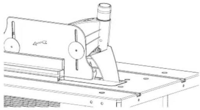
natural_image
Technical line drawing of a mechanical machine with rollers and mounting base (no text or symbols)[01] × 01
[02] × 04 [03] × 04


[04] × 02 [05] × 04 [06] × 04
natural_image
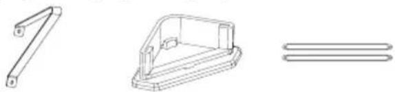
Technical line drawings of mechanical parts including a bracket, housing, and parallel plates (no text or symbols)1:1
[07] × 02
natural_image
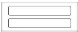
Two horizontal rectangular shapes with rounded corners, no text or symbols present.[08] × 01
natural_image
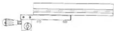
Pure mechanical assembly diagram without any text, numbers, or symbols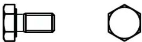
natural_image
Pure technical line drawing of a bolt and hexagonal nut (no text or symbols)[09] x 34
[10] × 26

[11] x 26

[12] x 01
natural_image
Simple curved line drawing without any text, numbers, or symbols[13] x 01
natural_image
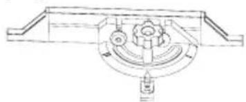
Technical line drawing of a mechanical assembly with no visible text or symbols[14] x 01
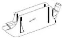
[17] × 01[16] × 01[15] × 01
natural_image
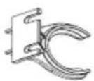
Technical line drawing of a mechanical machine with no visible text or symbolsRef : 3901306967
Read the entire operating instructions before installation and commissioning.
These operating instructions should make the familiarisation with your machine and its intended use easier.
Keep these instructions for future reference.
natural_image
Solid gray vertical bar with no text or symbolsLet's
get started...

Getting started...
Before you start 12
Safety 15
Assembly 23
Dust extraction 27
Connection of the power supply 27

In more detail...
| Technical datas | 30 | |
| Intended use | 31 | |
| Operation | 33 | |
| Working instructions | 38 | |
| Maintenance | 42 | |
| Electrical connection | 43 | |
| Trouble shooting | 45 | |
| EC declaration of conformity | 124 | |
| Recycling | 125 | |
| Warranty | 126 |

natural_image
Gray play button icon inside a circular frame (no text or symbols)Getting started...
Before you start 12
Safety 15
Assembly 23
Dust extraction 27
Connection of the power supply 27
natural_image
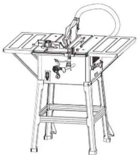
Technical line drawing of a mechanical machine with no visible text or symbolsThings to check before you start

Check all parts for possible transport damage after unpacking. The supplier must be informed immediately in case of complaints. Later complaints are not accepted.

Check the delivery for completeness.

Familiarise yourself with the device before using it by consulting the operating instructions.
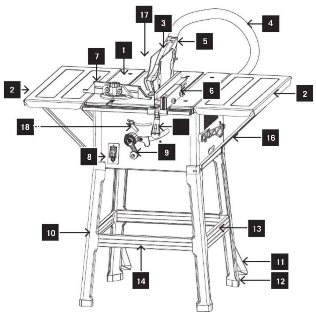
Your product
- Bench plate
- Bench widener
- Protective cover
- Extraction hose
- Splitting wedge
- Longitudinal stop
- Cross cutting gauge
- On/Off switch
- Height adjustment
- Stand leg
- Additional leg
- Rubber foot
- Cross struts
-
Horizontal struts
-
Rear support
- Side support
- Table length extension
- Fixing handle
- Longitudinal stop locking lever
- Saw blade
- Table insert
- Push stick
To assemble your product, consult the assembly guide located at page 23 of the guidebook
Your product
text_image
Technical diagram of a machine tool with numbered components for identification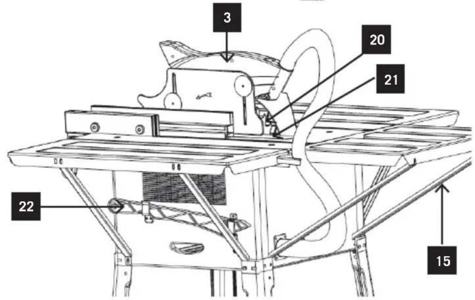
text_image
3 20 21 22 15You will need
To assemble your table saw
(items not supplied)
1 Hexwrench M6
13mm flat-end wrench
1 Helper for some tasks

General Safety
Check that you have noted all the following instructions:

Warning! Denotes risk of personal injury, loss of life, or damage to the tool in case of non-observance.

Wear ear protection.

Wear eye protection.

Wear respiratory protection.

The product complies with the applicable European directives and an evaluation method of conformity for this directives was done.

Read the instruction manual.

Wear protective gloves.

Switch the product off and disconnect it from the power supply before assembly, cleaning, adjustments, maintenance, storage and transportation

The table saw use for wood only.

Caution, risk of cutting.
WARNING: When operating power tools, the following general safety measures have to be taken in order to protect the user against electric shock, risk of injury and fire risk. Read through all of this information before operating this power tool and keep the safety information
General Safety
Safe work
1 Keep the work area orderly
– Disorder in the work area can lead to accidents.
2 Take environmental influences into account
- Do not expose electric tools to rain.
- Do not use electric tools in a damp or wet environment.
- Make sure that the work area is well-illuminated.
- Do not use electric tools where there is a risk of fire or explosion.
3 Protect yourself from electric shock
- Avoid physical contact with earthed parts (e.g. pipes, radiators, electric ranges, cooling units).
4 Keep children away
- Do not allow other persons to touch the equipment or cable, keep them away from your work area.
5 Securely store unused electric tools
- Unused electric tools should be stored in a dry, elevated or closed location out of the reach of children.
6 Do not overload your electric tool
- They work better and more safely in the specified output range.
7 Use the correct electric tool
- Do not use low-output electric tools for heavy work.
- Do not use the electric tool for purposes for which it is not intended. For example, do not use handheld circular saws for the cutting of branches or logs.
- Do not use the electric tool to cut firewood.
8 Wear suitable clothing
- Do not wear wide clothing or jewellery, which can become entangled in moving parts.
- When working outdoors, anti-slip footwear is recommended.
– Tie long hair back in a hair net.
9 Use protective equipment
- Wear protective goggles.
- Wear a mask when carrying out dust-creating work.
10 Connect the dust extraction device
- If connections for dust extraction and a collecting device are present, make sure that they are connected and used properly.
- Operation in enclosed areas is only permitted with a suitable extraction system.
General Safety
11 Do not use the cable for purposes for which it is not intended
- Do not use the cable to pull the plug out of the outlet. Protect the cable from heat, oil and sharp edges.
12 Secure the workpiece
- Use the clamping devices or a vice to hold the workpiece in place. In this manner, it is held more securely than with your hand.
- An additional support is necessary for long workpieces (table, trestle, etc.) in order to prevent the machine from tipping over.
- Always press the workpiece firmly against the working plate and stop in order to prevent bouncing and twisting of the workpiece.
13 Avoid abnormal posture
- Make sure that you have secure footing and always maintain your balance.
- Avoid awkward hand positions in which a sudden slip could cause one or both hands to come into contact with the saw blade.
14 Take care of your tools
- Keep cutting tools sharp and clean in order to be able to work better and more safely.
- Follow the instructions for lubrication and for tool replacement.
- Check the connection cable of the electric tool regularly and have it replaced by a recognised specialist when damaged.
- Check extension cables regularly and replace them when damaged.
- Keep the handle dry, clean and free of oil and grease.
15 Pull the plug out of the outlet
- Never remove loose splinters, chips or jammed wood pieces from the running saw blade.
- During non-use of the electric tool or prior to maintenance and when replacing tools such as saw blades, bits, milling heads.
16 Do not leave a tool key inserted
- Before switching on, make sure that keys and adjusting tools are removed.
17 Avoid inadvertent starting
- Make sure that the switch is switched off when plugging the plug into an outlet.
18 Use extension cables for outdoors
- Only use approved and appropriately identified extension cables for use outdoors.
- Only use cable reels in the unrolled state.
19 Remain attentive
- Pay attention to what you are doing. Remain sensible when working. Do not use the electric tool when you are distracted.
20 Check the electric tool for potential damage
- Protective devices and other parts must be carefully inspected to ensure that they are fault-free and function as intended prior to continued use of the electric tool.
- Check whether the moving parts function faultlessly and do not jam or whether parts are damaged. All parts must be correctly mounted and all conditions must be fulfilled to ensure fault-free operation of the electric tool.
- The moving protective hood may not be fixed in the open position.
- Damaged protective devices and parts must be properly repaired or replaced by a recognised workshop, insofar as nothing different is specified in the operating manual.
- Damaged switches must be replaced at a customer service workshop.
- Do not use any faulty or damaged connection cables.
- Do not use any electric tool on which the switch cannot be switched on and off.
21 ATTENTION!
- Exercise elevated caution for double mitre cuts.
22 ATTENTION!
- The use of other insertion tools and other accessories can entail a risk of injury.
23 Have your electric tool repaired by a qualified electrician
- This electric tool conforms to the applicable safety regulations. Repairs may only be performed by an electrician using original spare parts. Otherwise accidents can occur.
Additional Safety
1 Safety precautions
- Warning! Do not use damaged or deformed saw blades.
-
Replace a worn table insert.
-
Only use saw blades recommended by the manufacturer which conform to EN 847-1.
- Make sure that a suitable saw blade for the material to be cut is selected.
- Wear suitable personal protective equipment. This includes:
- Hearing protection to avoid the risk of becoming hearing impaired,
- Respiratory protection to avoid the risk of inhaling harmful dust,
- Wear gloves when handling saw blades and rough materials. Carry saw blades in a container whenever practical.
- Wear goggles. Sparks generated during work or splinters, chippings and dust coming from the device can lead to loss of eyesight.
- Connect a dust collecting device to the electric tool when sawing wood. The emission of dust is influenced, among other things, by the type of material to be processed, the significance of local separation (collection or source) and the correct setting of the hood/guide plates/guides.
- Do not use saw blades made of high-speed alloy steel (HSS steel).
- In times of non-use keep the push stick or the push block with the electrical power tool at all times.
- Use the upper blade guard and set it to the correct position.
2 Maintenance and repair
– Pull out the mains plug for any adjustment or repair tasks.
- The generation of noise is influenced by various factors, including the characteristics of saw blades, condition of saw blade and electric tool. Use saw blades which were designed for reduced noise development, insofar as possible. Maintain the electric tool and tool attachments regularly and if necessary, initiate repairs in order to reduce noise.
- Report faults on the electric tool, protective devices or the tool attachment to the person responsible for safety as soon as they are discovered.
3 Safe work
- Only use saw blades for which the maximum permissible speed is not lower than the maximum spindle speed of table saws and which are suitable for the material to be cut.
- Do not cut rebates or grooves without fitting a suitable guard, e.g. a tunnel-type guard, over the saw table.
- Circular saws must not be used for slotting jobs (cutting grooves which end in the workpiece).
- When transporting the electric tool, only use the transport devices. Never use the protective devices for handling or transport.
- Make sure that the lower part of the saw blade is covered during transport, e.g. by the protective device.
- Be sure to only use spacers and spindle rings specified by the manufacturer as suitable for the intended purpose.
- The floor around the machine must be level, clean and free of loose particles, such as chips and cutting residues.
- Do not remove any cutting residues or other parts of workpieces from the cutting zone while the machine is running and the saw unit is not at rest.
- Support long workpieces (e.g. with a roller table) to prevent them sagging at the end of a cut.
Warning! This electric tool generates an electromagnetic field during operation. This field can impair active or passive medical implants under certain conditions. In order to prevent the risk of serious or deadly injuries, we recommend that persons with medical implants consult with their physician and the manufacturer of the medical implant prior to operating the electric tool.
SAFETY INSTRUCTIONS FOR THE HANDLING OF SAW BLADES
1 Only use insertion tools if you have mastered their use.
2 Observe the maximum speed. The maximum speed specified on the insertion tool may not be exceeded. If specified, observe the speed range.
3 Observe the motor / saw blade direction of rotation.
4 Do not use any insertion tools with cracks. Sort out cracked insertion tools. Repairs are not permitted.
5 Clean grease, oil and water off of the clamping surfaces.
6 Do not use any loose reducing rings or bushes for the reducing of holes on saw blades.
7 Make sure that fixed reducer rings for securing the insertion tool have the same diameter and have at least 1/3 of the cutting diameter.
8 Make sure that fixed reducer rings are parallel to each other.
9 Handle insertion tool with caution. They are ideally stored in the originally package or special containers. Wear protective gloves in order to improve grip and to further reduce the risk of injury.
10 Prior to the use of insertion tools, make sure that all protective devices are properly fastened.
11 Prior to use, make sure that the insertion tool meets the technical requirements of this electric tool and is properly fastened.
12 Only use the supplied saw blade for cutting wood, never for the processing of metals.
Unpack and positioning
- Take the saw out of the box and place it on an even surface together with the bench plate - use a piece of cardboard as underlay to protect the bench surface.
- Check all parts for possible transport damage after unpacking. The supplier must be informed immediately in case of complaints. Later complaints are not accepted.
- Check the delivery for completeness.
- Prepare the workplace where the machine is supposed to be placed. Make sufficient space to ensure safe and trouble-free working. The machine is designed for use in enclosed rooms and must be placed on an even, firm and stable surface.
You will need
| Installation parts supplied Items not supplied | |
| 1 Housing complete with saw blade and splitting wedge | Suitable personal pro- tectiv equipment (eye protection, gloves) |
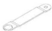
| 4 Feet 1 Ruler | |
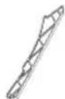
| 4 Foot stiffeners | |
| 2 Foot supports | |
| 4 Foot caps | |
| 4 Bench stiffeners | |
| 1 Extraction cover | |
| 1 Extraction hose | |
| 1 Retaining clamp for extraction hose | |
| 34 Hexagon screws M6 x 12 1 hexwrench M6 | |
| 26 Hexagon nuts M6 | |
| 26 Washers 8 mm | |
| 1 Longitudinal stop with guide rail | |
| 1 Cross cutting gauge | |
| 1 Saw blade key | |
| 1 Push stick | |
| 1 Operating instructions 13mm flat-end wrench |
Assembly
Mounting the frame (Fig. 1-4)
- Mount the individual parts and fasten the screws only manually.
- Turn the saw upside down and place it on the floor.
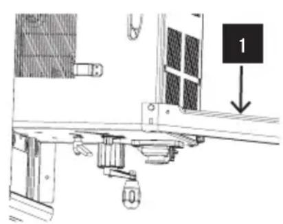
- Use the washers (5) and the hex screws (4) to fasten the 4 legs (1) loosely to the saw.
- Now use the hex screws (4), the washers (5) and the nuts (6) to fasten the longitudinal struts (3) and the cross-struts (2) loosely to the legs.
- Please note: The longer struts have to be used on the sides.
- Finally, tighten all screws and nuts on the base frame.
- Screw the additional legs (8) to the rear legs (1) so that they point towards the rear of the machine (Fig. 4).
- Attach the foot caps (7) by tapping slightly.
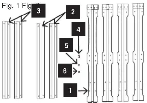
flowchart
graph TD
    A["1"] --> B["2"]
    B --> C["3"]
    C --> D["4"]
    D --> E["5"]
    E --> F["6"]
    F --> G["End"]
text_image
1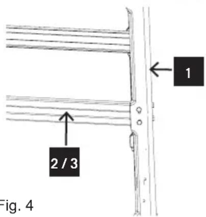
text_image
2 / 3 Fig. 4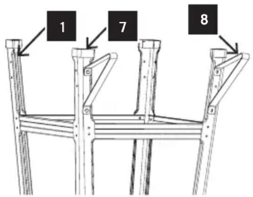
text_image
1 7 8Fig. 3 Fig. 4
Assembly
Install the bench widener
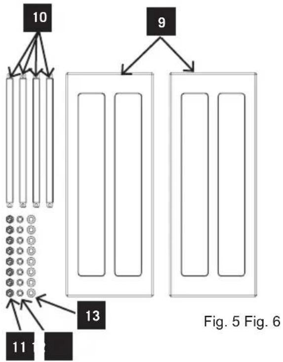
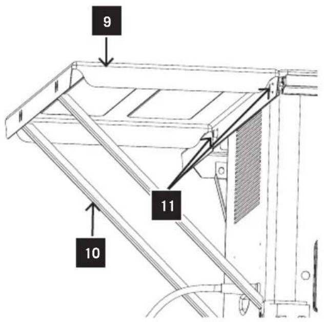
- Mount the bench stiffeners to both sides of the bench plate (Fig. 5).
- Use four screws(11), washer(12) and two nuts(13) to fit the bench stiffeners(10) and mount it to the bench plate(9).
- Screw the supports (3/2) loosely onto the saw housing and onto the table width extensions
- Erect the circular saw bench on its feet on an even surface.
- Lay a ruler over bench plate and wideners.
- Align the bench plate and tighten all screws.
- Check the bench plate for vertical alignment, re-adjust if necessary.
flowchart
graph TD
    A["10"] --> B["9"]
    B --> C["13"]
    C --> D["Fig. 5 Fig. 6"]
    style A fill:#f9f,stroke:#333
    style B fill:#ccf,stroke:#333
    style C fill:#cfc,stroke:#333
    style D fill:#fcc,stroke:#333
text_image
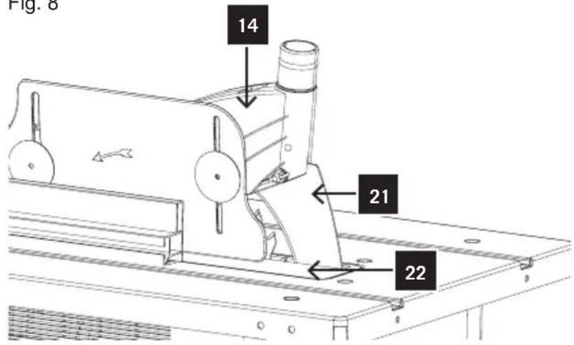
9 11 10Fitting / removing the protective cover and install extraction hose (Fig. 7-8)
- Mount the retaining clamp(16) for the extraction hose with two screws(17), washer(19) and two nuts(18).
- Place the protective cover (14) together with the screw on top of the riving knife (21) so that the screw is snug in the oval hole.
- Do not tighten the screw too far – the blade guard must be able to move freely.
- Fasten the extractor hose (15) to the extractor adapter (20) and to the extractor socket of the protective cover (14).
-
A suitable extractor system has to be connected to the outlet of the extractor adapter (20). Make sure that the extraction hose is stuck in the holder.
-
To remove the saw blade guard, proceed in reverse order. Fig. 7

text_image
g. 7 14 15 16 20 17 18 19
Important!
The protective cover(14) must always be lowered over the workpiece before cutting.
Note! The protective cover should return to its rest position after the workpiece has been sawn
Caution!
The protective cover(14) must be in position at all times to prevent contact with the blade. It should lift up and onto the workpiece when the workpiece is passed through the saw (Fig. 8).
Fig. 8
text_image
Fig. 6 14 21 22Setting the splitter (Fig. 8.1)
- Important! Pull out the power plug.
- Set the blade (16) to max. cutting depth, move to 0^ position and lock in place.
- Remove the protective cover (14).
- Take out the table insert.
- Slacken the fixing screw (17).
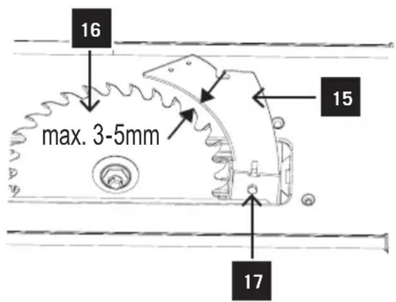
Setting for maximum cuts (Fig. 8.1)
- Push up the splitting wedge (15) until the gap between the saw table and the upper edge of the splitting wedge (15) equals approx. 10 cm.
- The distance between the blade (16) and the Splitting wedge (15) should be 3-5 mm.
- Retighten the screw (17) and mount the table insert.
Fig. 8.1
text_image
16 max. 3-5mm 15 17Changing the table insert
- To prevent increased likelihood of injury the table insert should be changed whenever it is worn or damaged.
- Remove the protective cover (14).
- Remove the 1 countersunk head screw.
- Take out the worn table insert (22).
- To fit the replacement table insert, proceed in reverse order.
Dust extraction
Notes on dust emission
The dust emission values measured according to the “Guidelines for the test of dust emission (concentration parameter) for wood processing machines” by the technical wood committee are below 2 mg/m3. Thus, a consistently safe compliance with the TRK threshold value for wood dust applicable in the Federal Republic of Germany can be assumed when connecting the machine to a proper extraction device with an air speed of at least 20 m/s

WARNING!
Attach a dust extraction device when using this product in order to keep the working area clean!
Wear a dust mask when operating this product. Dust can be harmful to your health!
Electrical connection
- Connect the pulg with a suitable socket.
- Your porduct is now ready to be used.

WARNING!
Check the voltage!
The voltage must comply with the information on the rating label!

natural_image
Gray magnifying glass icon with three small squares inside, enclosed in a circular frame (no text or symbols)In more detail...
Technical datas 30
Intendend use 31
Operation 33
Working instructions 38
Maintenance 42
Electrical connection 43
Trouble shooting 45
EC declaration of conformity 124
Recycling 125
Warranty 126
natural_image
Line drawing of a mechanical machine with no visible text or symbolsTechnical data
| FPTS1500 | |
| Technical data | |
| Dimensions L x W x H | 950 x 850 x 1200 mm |
| Bench size | 640 x 445 mm |
| Bench size with widener | 640 x 945 mm |
| Bench height with base frame | 850 mm |
| ø saw blade | 250 x 30 x 2,4/1.8 Z 24 WZ |
| Height adjustment 90°/45° | 0–73/0–65 mm |
| Tilt range | 90°–45° |
| Cutting speed m/sec | 80 |
| Longitudinal stop | 445 x 640 mm |
| Cutting width left/right | 90/200 mm |
| Weight | 24,5 kg |
| Drive | |
| Motor V/Hz | 230 V/50 Hz |
| Input power | 1200 W S1 / 1500 W S6 40% |
| Mode of operation | S1 / S6 40 % |
| Rotational speed | 6000 |
| Motor protection | IP 20 |
| Low voltage circuit breaker | yes |
| Plug | Isolated earth |
Technical changes reserved!
Noise parameters
Measurement conditions
The specified values are emission values and do not necessarily represent proven working values. Although there is a correlation between emission and imission levels, it cannot be reliably concluded whether protective measures are required or not. Factors affecting the imission level present at the working place include the duration of exposure, the characteristics of the working room, other sources of noise, etc., e.g. the number of machines and adjacent procedures. Reliable working values may also vary from country to country. However, this information is meant to enable the user to evaluate dangers and risks better.
Sound power level in dB
Processing LWA = 94.0 dB (A)
For the specified emission values, a measurement uncertainty of K = 4 dB must be added.
Intended use
The machine complies with the applicable EG guideline for machines.
- The circular saw bench is defined as a portable machine.
- The machine has a work station situated in front of the machine and on the left to the saw blade.
- The work station and surroundings of the machine must be kept free from disturbing objects to prevent accidents.
- On principle, the workpieces to be processed must be free from foreign material such as nails or screws.
- The machine must be connected to an extraction unit with a flexible, flame resistant extraction hose before commissioning the machine. The extraction unit must switch on automatically when the circular saw bench is switched on. The air speed at the extraction nozzle must be 20 m/s. Do not switch on or remove the extraction unit or the deduster when the machine is running.
- Only operate the machine as intended in technically acceptable conditions, considering the operating instructions and bearing safety and risk issues in mind! Have faults that may impair the safety corrected immediately.
- The safety, work and maintenance regulations of the manufacturer as well as the dimensions specified under Technical data must be complied with.
- The applicable accident prevention regulations and other generally accepted safety-related regulations must be adhered to.
- The machine must only be operated, maintained or repaired by persons who are familiar with it and instructed concerning possible risks. Unauthorised modifications of the machine exclude the manufacturer's liability for resulting damage.
- The machine must only be operated with the manufacturer's original parts and tools.
- Any other use is considered as improper. The manufacturer is not liable for resulting damage; the risk is solely with the user.
Please note that our equipment has not been designed for use in commercial, trade or industrial applications. Our warranty will be voided if the machine is used in commercial, trade or industrial businesses or for equivalent purposes.
Remaining risks:
The machine is manufactured according to the technical state of the art and accepted safety-related regulations. However, individual remaining risks may occur during use.
- Risk of injury of fingers and hands due to the rotating saw blade when guiding the workpiece inappropriately.
- Injuries if the workpiece is thrown away when holding and guiding it inappropriately, e.g. working without stop.
- Health risk due to noise. The admissible noise level is exceeded during working with this machine. Always wear personal protective equipments such as hearing protection.
- Injuries due to faulty saw blade. Check the saw blade regularly and before each use for damage.
- Danger due to electricity, use of improper electric connection cables.
- When using special equipment, the operating instructions of this equipment must be read thoroughly and complied with.
• Furthermore, less obvious remaining risks can exist despite all protective measures. - Remaining risks can be minimised, if the safety instructions and Intended use as well as the entire operating instructions are observed.
Operation
Observe the safety instructions!
Important note: The machine must only be commissioned when the protection and safety equipment is completely mounted.
Connect the machine to an extraction unit before commissioning.
The extraction cover must be lowered onto the workpiece during each process step.
The machine must be set up so that the tip of the highest saw tooth is a little higher than the workpiece.
All protection and safety equipment must be mounted correctly before switching on the machine.
The saw blade must be freely moveable.
Check the wood for foreign materials (nails, screws, etc.), if it has been processed before. Remove all foreign materials.
Before pressing the main switch, make sure that the saw blade is mounted correctly and that the moveable parts are smooth-running.
Warning: If you have any doubts, have a specialist set up the machine. It is dangerous to work based on assumptions.
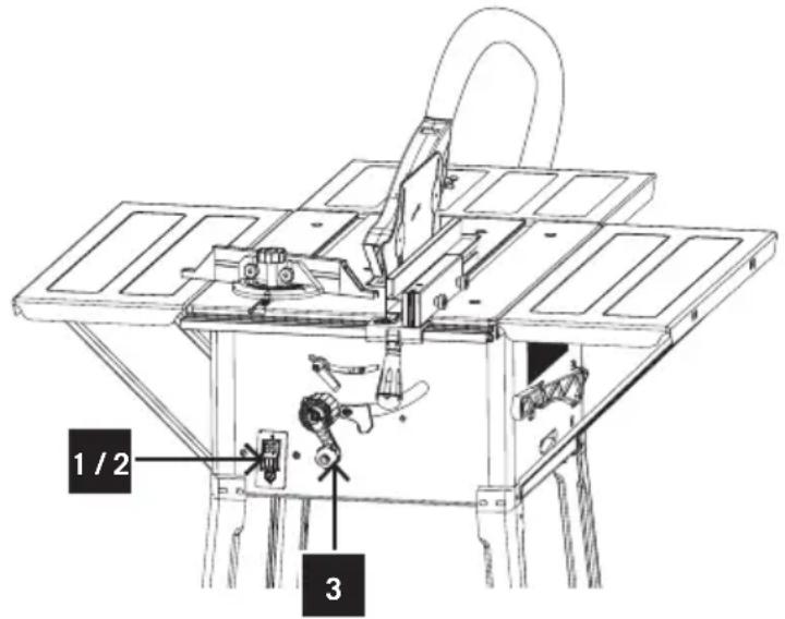
Switching on and off (Fig. 9)
- Press the green button „I“ (1) to switch the machine on. Wait for the blade to reach its maximum speed of rotation before commencing with the cut.
- Press the red button „0“ (2) to switch the machine off.
Adjusting the cutting depth (Fig. 9)
Fig. 9
text_image
1 / 2 3- Adjust the desired cutting depth by turning the height adjusting crank(3).
- Turning in counter-clockwise direction increases the cutting depth.
- Turning in clockwise direction decreases the cutting depth.
Using the longitudinal stop
Cutting width (Fig. 10)
- Use the longitudinal stop for longitudinal cuts.
- The longitudinal stop (5) can be fixed to each side of the bench plate.
- To use the scale, move the stop to the saw blade and measure the distance at the scale. Now slide the stop away from the saw blade. The measured difference corresponds to the cutting depth. In order to obtain an exact value, it is necessary to make a test cut, measure the workpiece and re-adjust the stop.
- Lift the locking lever and slide the stop into the desired position.
- Pull the locking lever tight again.
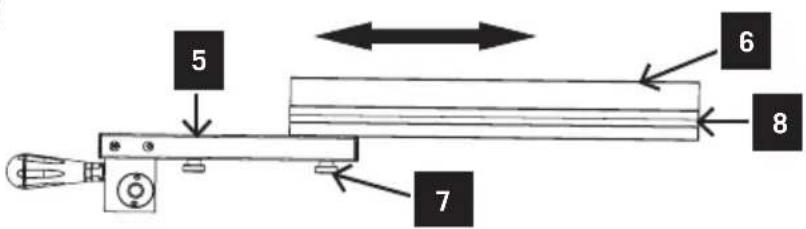
Stop height (Fig. 10.1-10.2)
- The longitudinal stop (5+6) supplied with the benchtype circular saw has two different guide faces.
- For thick material you must use the longitudinal rail (5) as shown in Fig. 10.1, for thin material you must use the stop rail as shown in Fig.10.2.
- To change over the longitudinal rail (5+6) to the lower guide face you have to slacken the two knurled screws (7) in order to disconnect the longitudinal rail (6) from the holder (5).
- Remove the two knurled screws (7) through the one slot (8) in the longitudinal rail (6) and insert in the other slot.
Fig. 10.2
text_image
5 6 7 8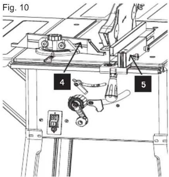
text_image
Fig. 10 4 5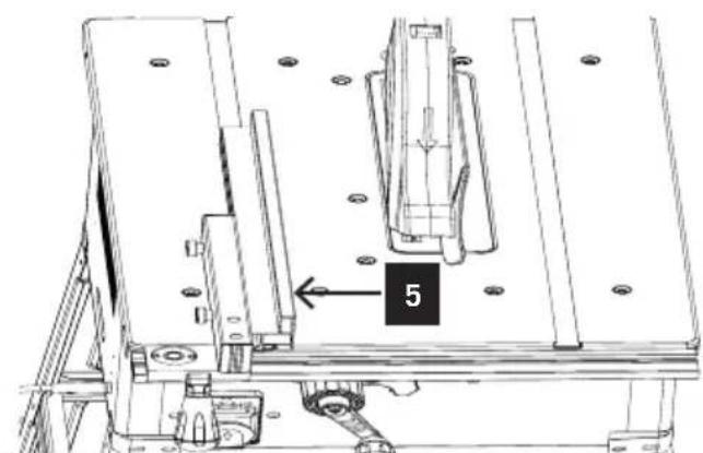
natural_image
Technical line drawing of a mechanical assembly with labeled component '5' (no text or symbols beyond label)Fig. 10.1
- Remount the longitudinal rail (6) on the holder (5).
- The procedure for changing over to the high guide face is similar.
Setting the stop length
- The stop rail (5) can be moved in longitudinal direction in order to prevent the workpiece from becoming jammed.
- Rule of thumb: The rear end of the stop comes up against an imaginary line that begins roughly at the center of the blade and runs at an angle of 45^ to the rear.
- Set the required cutting width
- Slacken the knurled screws and push the stop rail (5) forward until it touches the imaginary 45^ line.
- Retighten the knurled screws.

WARNING!
The longitudinal stop must always be adjusted so that it is parallel to the saw blade. Check this together with the tension of the fixing elements in regular intervals, and always when the saw has not been used for several days.
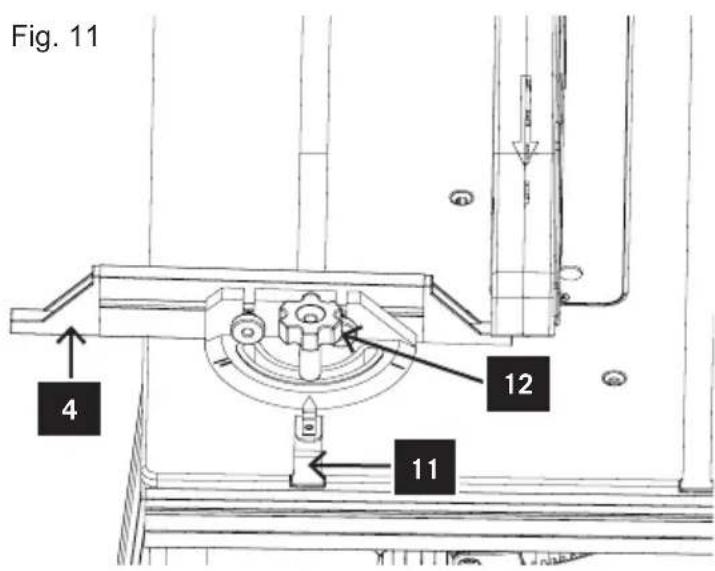
Using the cross cutting gauge (Fig. 11)
- Slide the cross cutting gauge (4) into the groove (11) of the table.
- Slacken the knurled screw (12).
- Turn the cross cutting gauge (4) until the arrow points to the angle required.
• Retighten the knurled screw (12). - To move the stop from one side of the quadrant, loosen both plastic screws that fix the stop, remove the stop, place it on the other side and tighten the plastic screws again.
Important!
- Do not push the longitudinal stop (5) too far toward the blade.
- The distance between the longitudinal stop (5) and the saw blade should be approx. 2 cm.
Adjusting the saw blade angle (Fig. 12)
- Loosen the saw blade lock (9) and turn the handle (3) until the indicator(6) points to the correct angle on the scale (10).
- The angle indication(6) can be adjusted when checking the angle accuracy of the saw blade. Hold an angle against the saw blade when the machine is switched off and the power supply unit is disconnected. Adjust the handle until the saw blade is parallel to the angle. Then, move the indicator to 0^ on the scale.
- Lock after adjusting.
Setting the angle (Fig. 12.1)
- Undo the fixing handle (9).
- Turn the handle to set the desired angle on the scale.
- Lock the fixing handle again in the required angle position.
text_image
Fig. 11 4 12 11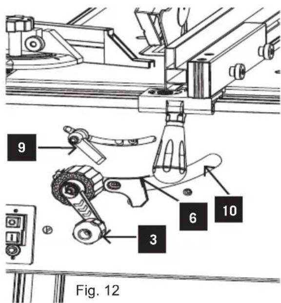
text_image
9 6 10 3 Fig. 12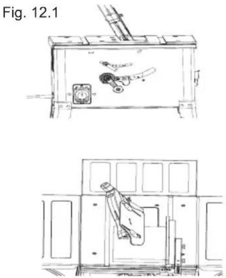
natural_image
Technical line drawing of a train interior showing front and side views with no visible text or symbols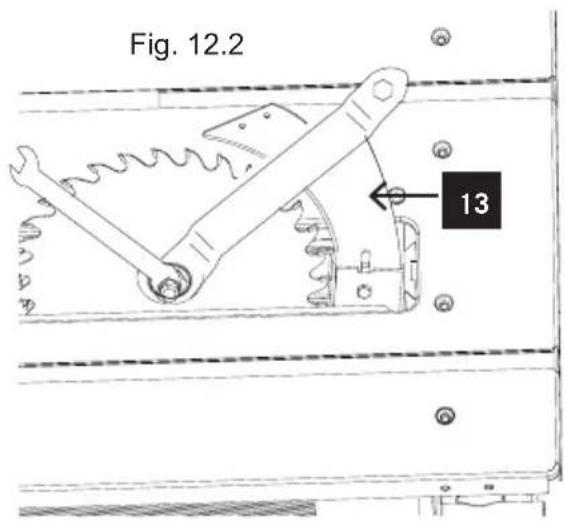
text_image
Fig. 12.2 13Replacing the saw blade (Fig. 12.2)
- Remove the table insert by undoing the two countersunk head screws.
- Undo the nut with a size 24 wrench on the nut itself and a second fork wrench (size 13) on the motor shaft to apply counter-pressure.
- Important! Turn the nut in the direction of rotation of the saw blade.
- Take off the outer flange and pull the old saw blade off the inner flange by dropping the blade at an angle.
- Clean the blade flange thoroughly before fitting the new blade.
- Mount and fasten the new saw blade in reverse order.
- Important! Note the running direction. The cutting angle of the teeth must point in running direction, i.e. forwards (see the arrow on the blade guard).
- Refit and set the splitting wedge (13) and the protective cover.
- Check to make sure that all safety devices are properly mounted and in good working condition before you begin working with the saw again.

WARNING!
Switch the machine off and disconnect the power supply unit before making any adjustments or carrying out maintenance works, or replacing the saw blade.
Wear gloves when handling the saw blade.
Working instructions

IMPORTANT!!!
- After every new adjustment we recommend you to make a trial cut in order to check the new settings.
- After switching on the saw, wait for the blade to reach its maximum speed of rotation before commencing with the cut.
• Take extra care when starting the cut! - Never use the equipment without the suction function. Regularly check and clean the suction channels.
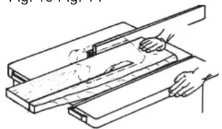
Making longitudinal cuts (Fig. 13)
Longitudinal cutting (also known as slitting) is when you use the saw to cut along the grain of the wood.
Press one edge of the workpiece against the longitudinal stop while the flat side lies on the saw table.
The protective cover must always be lowered over the workpiece.
When you make a longitudinal cut, never adopt a working position that is in line with the cutting direction.
- Set the longitudinal stop in accordance with the workpiece height and the desired width.
- Switch on the saw.
- Place your hands (with fingers closed) flat on the workpiece and push the workpiece along the longitudinal stop and into the saw blade.
- Guide at the side with your left or right hand (depending on the position of the parallel stop) only as far as the front edge of the guard hood.
• Always push the workpiece through to the end of the splitting wedge. - The offcut piece remains on the saw table until the saw blade is back in its position of rest.
- Secure long workpieces against falling off at the end of the cut (e.g. with a roller stand etc.).
Working with circular saw benches
Cutting wide workpieces (Fig. 13)
Width of the workpiece to be cut is more than 120 mm.
Tool: circular saw blade for longitudinal cuts
Process steps: Adjust the longitudinal stop according to the intended width
of the workpiece. Mind the position of your hand. If narrow pieces are cut off, the workpiece is moved forward in the tool area only with the right hand or by using a push stick. If there is a risk that the workpiece might get jammed between circular saw blade, splitting wedge and stop, the stop must be pulled back to the middle of the saw blade or a short additional stop must be used. The upper extraction cover was only indicated in the figures or omitted in individual cases in order to show the process step or equipment more clearly. The upper extraction cover is required for all depicted process steps.
Fig. 13 Fig. 14
natural_image
Line drawing of a hand using a tool to cut or spread a wooden plank (no text or symbols)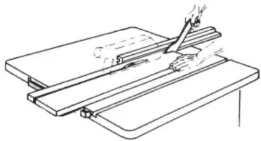
natural_image
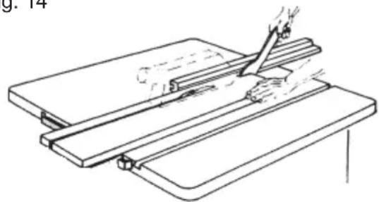
Line drawing of a hand using a tool to cut or mark a piece on a flat surface (no text or symbols)Cutting narrow workpieces (Fig. 14)
Be sure to use a push stick (22) when making longitudinal cuts in workpieces smaller than 120 mm in width. A push block is supplied with the saw! Replace a worn or damaged push stick immediately.
Tool: circular saw blade for longitudinal cuts
Process steps: Adjust the longitudinal stop according to the intended width of the workpiece. Move the workpiece forward with both hands; use the push stick in the saw blade area and push the workpiece forwards until it is behind the splitting wedge. Use the push stick from the beginning for very short workpieces.
Cutting extremely narrow workpieces. Be sure to use a push block when making longitudinal cuts in very narrow workpieces with a width of 30 mm and less.
The low guide face of the longitudinal stop is best used in this case.
Replace the push block without delay when it becomes worn.
There is no push block supplied with the saw! (Available from your specialist dealer) Replace the push block without delay when it becomes worn.
natural_image
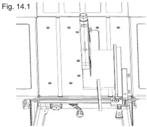
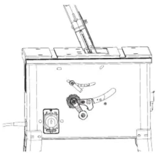
Technical line drawing of a mechanical assembly with mounting brackets and a central vertical component (no text or symbols)Making bevel cuts (Fig. 15)
Bevel cuts must always be used using the longitudinal stop.
Set the saw blade to the desired angle. (See Fig. 12.1)
Set the longitudinal stop in accordance with the workpiece width and height (see Fig. 10.1 + 10.2)
Carry out the cut in accordance with the workpiece width.
Making cross cuts (Fig. 16)
Slide the cross cutting gauge (1) into one of the grooves in the table and adjust to the required angle. (see Fig. 11)
If you also want to tilt the swa blade, use the groove which prevents your hand and the cross stop from making contact with the blade guard.
Press the workpiece firmly against the cross cutting gauge (1).
Switch on the saw.
Push the cross cutting gauge (1) and the workpiece toward the blade in order to make the cut.
Push the cross cutting gauge (1) forward until the workpiece is cut all the way through.
Switch off the saw again. Do not remove the offcut until the blade has stopped rotating.

IMPORTANT!!!
Always hold the guided part of the workpiece. Never hold the part which is to be cut off.
Fig. 15
Fig. 16
natural_image
Technical line drawing of a mechanical assembly with internal components (no text or symbols)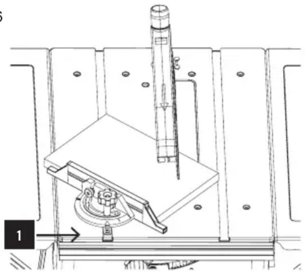
natural_image
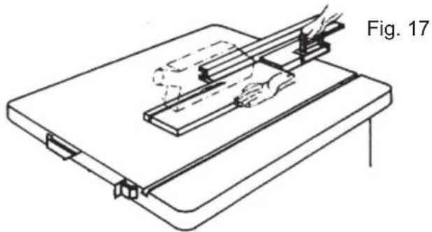
Technical line drawing of a mechanical assembly with a cylindrical component and a base mount (no text or symbols)Cutting of edges and slats (Fig. 17)
Tool: circular saw blade for fine cuts
Process steps: Mount the longitudinal stop with a low contact area or use an additional stop. Move the workpiece forward with the push stick until the end of the workpiece reaches the splitting wedge. Secure long workpieces against tilting with a bench extension at the end of the cutting process.
Note: Devices that have to be connected with parts of the machine have to be fixed with screws; only auxiliary connections to the machine can be made with screw clamps.
natural_image
Technical line drawing of a mechanical setup with hands operating a tool on a flat base (no text or symbols)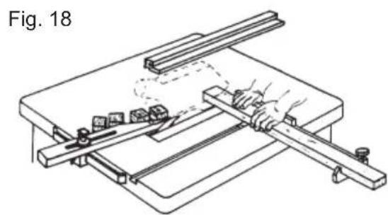
natural_image
Technical line drawing of a mechanical setup with a hand operating a workbench and a tool, labeled Fig. 18 (no text or symbols on the diagram itself)Cross cutting narrow workpieces (Fig. 18)
Tool: cross cutting blade with fine teeth
Process steps: Adjust the rod so that the workpiece cut-offs cannot touch the ascending part of the saw blade. Move the workpieces with cross stops or cross pushers.
Do not use your hands to remove waste from the workpiece.
Maintenance

WARNING!
Switch the machine off and disconnect it from the mains voltage before carrying out any maintenance and adjustment works.
The golden rules of care
- Keep the instructions near the machine.
- Keep the machine clean.
- Wear protective goggles when cleaning the machine.
-
Inspect the product before each use for worn and damaged parts. Do not operate it if you find broken or worn parts.
-
Check the saw blade regularly. Only use sharpened, crack-free and non-deformed saw blades. Only use tools that comply with the European standard EN847-1.
- Replace a worn bench insert immediately.
• Always keep the bench surface free of resin. - Clean the inside of the machine such as tooth segment and bevel of the tilting system regularly from residual wood and splints.
- Remove possible saw dust obstructions at the ejector.

CAUTION:
Do not clean plastic parts of the bench with aggressive agents. A mild rinsing agent on a wet cloth is recommended. The machine must not get in contact with water.
Repair:
This product does not contain any parts that can be repaired by the consumer. Contact a qualified specialist to have it checked and repaired.

WARNING!
Only perform repairs and maintenance work according to these instruction! All further works must be performed by a specialist.
Electrical connection
The installed electric motor is connected and ready for operation. The connection complies with the applicable VDE and DIN regulations.
The mains connections provided by the client as well as the used extension cable must comply with these regulations.

Important notes!
The electric 230 V/50 Hz motor is designed for operating mode 1200 W S1 / 1500 W S6 40%.
If overloaded, the motor switches off automatically. After a cooling-down period (varies in time), the motor can be switched on again.
Damaged electrical connection cables
Insulation damage often occurs on electrical connection cables.
Reasons are:
- Pressure, if the connection cable is drawn through windows or doors.
- Kinks due to improper fixing or drawing of the connection cable.
- Cuts due to running over the connection cable.
• Insulation damage due to pulling out of the mains socket. - Ruptures due to aging of the insulation.
Such damaged electrical connection cables must not be used and are a danger to life due to their insulation damage.
Check electrical connection cables regularly for such damage. Make sure that the connection cable is not live when checking.
Electrical connection cables must comply with the applicable VDE and DIN regulations. Only use connection cables with the label H 07 RN.
A label on the connection cable indicating the type is stipulated.
Alternating current motor
• The mains voltage must be 230 volts - 50 Hz.
- Extension cables must have a cross-section of 1.5 ~mm 2 up to a length of 25 ~m , and at least 2.5 ~mm 2 for a length of 25 ~m and more.
• The mains connections is secured with 16 A.
For enquiries, please specify the following information:
- Motor manufacturer
• Kind of motor current
• Information of the machine type label
When returning the motor, always include the complete drive unit.
Connection and repair of the electrical equipment must only be done by an electrical specialist.
Observe the safety instructions!
Serial number information
The serial numbers on the product and its packaging indicates:
- The year and week of manufacture
- The product number in the lot
Trouble shooting
| Error Possible reason Remedy | ||
| 1.Saw blade comes loose after switching off the motor? | Fastening nut is too loose. | Tighten the fastening nut (right-handed thread) |
| 2.Motor does not start? | Failure of mains fuse a) | Check mains fuse |
| b) Extension cable is defective | b) Replace extension cable | |
| c) Connections at motor or switch are not ok | c) Must be checked by electrician | |
| d) Motor or switch are effective | d) Must be checked by electrician | |
| 3.Wrong direction of motor rotation? | a) Condenser defective a) | Must be checked by electrician |
| b) Incorrect connection b) | Reverse of polarity of the mains socket by electrician | |
| 4.Motor does not perform, fuse does not activate? | a) Cross-sectional area of extension cable is not sufficient | a) see electrical connection |
| b) Overloading due to blunt saw blade | b) Replace saw blade | |
| 5.Fire stains at cutting surface? | a) Blunt saw blade a) | Sharpen, replace saw blade |
| b) Wrong saw blade b) | Replace saw blade | |

natural_image
Solid gray vertical bar with no text or symbolsC'est parti...

natural_image
Row of ten black circular dots on white background (no text or symbols)
natural_image
Gray play button icon inside a circular frame (no text or symbols)natural_image
Technical line drawing of a mechanical machine with no visible text or symbolstext_image
Technical diagram of a mechanical assembly with numbered components for identification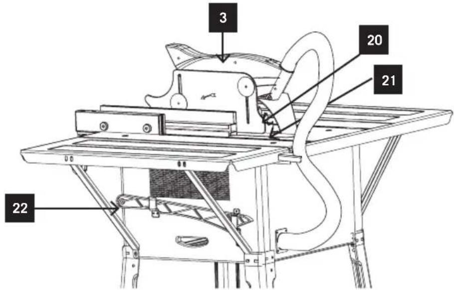
text_image
3 20 21 22Il vous faut
natural_image
Row of ten black circular dots on white background (no text or symbols)
natural_image
Gray magnifying glass icon with three small squares inside, enclosed in a circular frame (no text or symbols)natural_image
Technical line drawing of a mechanical machine with no visible text or symbolsnatural_image
Technical line drawings of a train interior showing front and side views with no visible text or symbols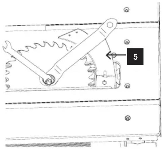
text_image
5natural_image
Line drawing of a hand using a tool to cut or spread a wooden plank (no text or symbols)Fig. 14
natural_image
Line drawing of a hand using a tool to cut or mark a wooden plank (no text or symbols)natural_image
Technical line drawing of a mechanical assembly with mounting brackets and structural supports (no text or symbols)natural_image
Technical line drawing of a mechanical assembly with internal components (no text or symbols)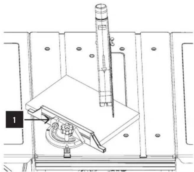
natural_image
Technical line drawing of a mechanical assembly with a cylindrical component and a labeled component (no text or symbols present)natural_image
Technical line drawing of a mechanical assembly with a tool and base plate (no text or symbols)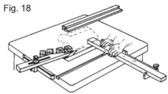
natural_image
Line drawing of a mechanical setup with a hand operating a tool on a workbench, no text or symbols presentnatural_image
Solid gray vertical bar with no text or symbolsJetzt
geht's los...

Einstieg...
natural_image
Row of nine black circular dots on white background (no text or symbols)
natural_image
Gray play button icon inside a circular frame (no text or symbols)Einstieg...
natural_image
Technical line drawing of a mechanical machine with no visible text or symbolstext_image
Technical diagram of a machine tool with numbered components for identification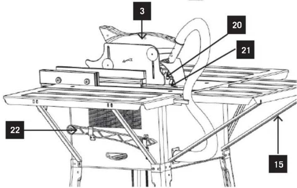
text_image
3 20 21 22 15Sie benötigen
natural_image
Simple line drawing of a wrench (no text or symbols)natural_image
Technical diagram of a mechanical assembly with labeled component '1' (no text or symbols beyond label)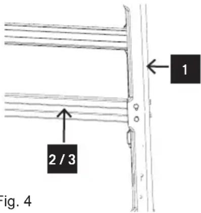
text_image
2 / 3 1 Fig. 4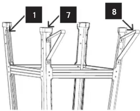
text_image
1 7 8Fig. 3 Fig. 4
Montage
natural_image
Gray magnifying glass icon with three small squares inside, enclosed in a circular frame (no text or symbols)Im Detail...
natural_image
Line drawing of a manual machine tool with no visible text or symbolsTechnische Daten
natural_image
Technical line drawings of a train interior showing front and side views, no text or symbols present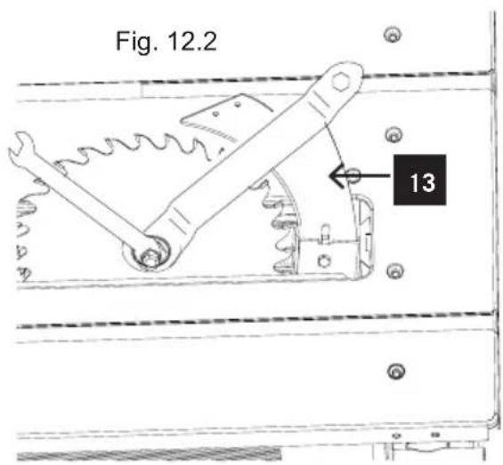
text_image
Fig. 12.2 13natural_image
Line drawing of a hand using a tool to lift or adjust a wooden plank (no text or symbols)
natural_image
Line drawing of a hand using a tool to cut or mark a piece on a flat surface (no text or symbols)natural_image
Technical line drawing of a mechanical assembly with mounting brackets and structural supports (no text or symbols)natural_image
Technical line drawing of a mechanical assembly with no visible text or symbols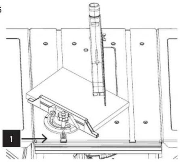
natural_image
Technical line drawing of a mechanical assembly with a cylindrical component and a base plate (no text or symbols)natural_image
Technical line drawing of a mechanical assembly with a hand operating a tool, labeled Fig. 17 (no text or symbols on the diagram itself)
natural_image
Technical line drawing of a mechanical setup with a hand operating a lever and multiple supports (no text or symbols)text_image
Technical diagram of an electronic device with numbered components and exploded view, likely for assembly or maintenance purposes.
text_image
Technical diagram of a mechanical assembly with numbered components and exploded views• Directive machine 2006/42/EC
(Annex IV: Notified Body: TÜV Rheinland LGA Products GmbH; Tillystraße 2, 90431 Nürnberg - Germany; Notified Body No.: 0197)
Only for EU countries.
Do not dispose of electric tools together with household waste material! In observance of European directive 2012/19/EU on wasted electrical and electronic equipment and its implementation in accordance with national law, electric tools that have reached the end of their life must be collected separately and returned to an environmentally compatible recycling facility.
FR