TD-003-05WFR - Bike accessory Vevor - Free user manual and instructions
Find the device manual for free TD-003-05WFR Vevor in PDF.

| Product Type | Dirt bike stand |
| Brand | Vevor |
| Model | TD-003-05WFR |
| Maximum Load Capacity | 1100 lb (approx. 499 kg) |
| Stand Height | 13.8 inches (approx. 35 cm) |
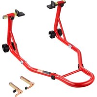
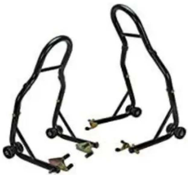
| Main Functions | Front and rear wheel support, use with paddle or fork adapters |
| Material | Robust steel |
| Included Accessories | Paddle and fork adapters, screws, nuts, washers |
| Safety | Respect maximum load capacity, read precautions before use, do not use under influence |
| Maintenance and Cleaning | Keep work area clean and well-lit, store out of reach of children |
| Spare Parts and Repairability | Parts list provided in manual, contact technical support for parts |
| General Information | Technical support and electronic warranty certificate at www.vevor.com/support |
Frequently Asked Questions - TD-003-05WFR Vevor
User questions about TD-003-05WFR Vevor
0 question about this device. Answer the ones you know or ask your own.
Ask a new question about this device
Download the instructions for your Bike accessory in PDF format for free! Find your manual TD-003-05WFR - Vevor and take your electronic device back in hand. On this page are published all the documents necessary for the use of your device. TD-003-05WFR by Vevor.
USER MANUAL TD-003-05WFR Vevor
Technical Support and E-Warranty Certificate www.vevor.com/support
DIRT BIKE STAND
MODEL: TD-003-05WFR
We continue to be committed to provide you tools with competitive price. "Save Half", "Half Price" or any other similar expressions used by us only represents an estimate of savings you might benefit from buying certain tools with us compared to the major top brands and does not necessarily mean to co all categories of tools offered by us. You are kindly reminded to verify carefully when you are placing an order with us if you are actually Saving Half in comparison with the top major brands.
VEVOR®
Dirt Bike Stand
Model: TD-003-05WFR
natural_image
Two black metal chain linkages with attached clips, no text or symbols visibleNEED HELP? CONTACT US!
Have product questions? Need technical support? Please feel free to contact us:
Technical Support and E-Warranty Certificate www.vevor.com/support
This is the original instruction, please read all manual instructions carefully before operating. VEVOR reserves a clear interpretation of o user manual. The appearance of the product shall be subject to the product you received. Please forgive us that we won't inform you ag there are any technology or software updates on our product.
SAFETY PRECAUTIONS
| Warning - To reduce the risk of injury, user must read instruct manual carefully. |
- Read and understand this entire manual before assembling, installing operating, or servicing this product. Failure to follow these warning and instructions can cause death, personal injury or damage to valuable property.
- Adhere to all Department of Transportation (D.O.T.) requirements when using this product.
- Use common sense when working. Stay alert and concentrate when setting up and using this product. Never work while under the inf of alcohol, drugs or medications.
● While assembling and using this product keep work area clean and well lighted. Keep spectators and children out of the work area. - Dress appropriately. Never wear loose fitting clothing or jewelry whe working. Contain long hair, and keep hair, clothing and gloves aw from moving parts.
● Always keep this stand away from children. - Check the stand is in good condition before using it.
SPECIFICATIONS
| Model Series | TD-003-05WFR |
| Maximum Load Capacity (lbs) | 1100 |
| Support height (inch) | 13.8 |
PRODUCT PARAMETERS
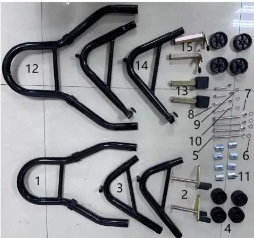
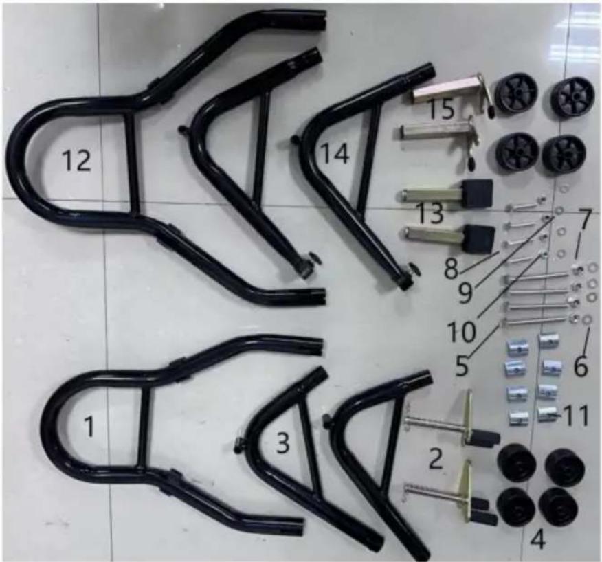
| SN | Description | Qty |
| 1 | Description | 1 |
| 2 | Front - wheel main tube | 2 |
| 3 | Front - wheel double - fork | 2 |
| 4 | Front - wheel support tube | 8 |
| 5 | Wheel | 4 |
| 6 | Screw M10×110mm | 4 |
| 7 | Washer d10mm | 4 |
| 8 | M10 nut | 4 |
| 9 | Screw M8×45mm | 4 |
| 10 | Washer d8mm | 4 |
| 11 | M8 nut | 8 |
| 12 | Fixing plate | 2 |
| 13 | Rear - wheel main tube | 2 |
| 14 | L - shaped fork | 2 |
| 15 | Rear - wheel support tube | 2 |
INSTALLATION INSTRUCTIONS
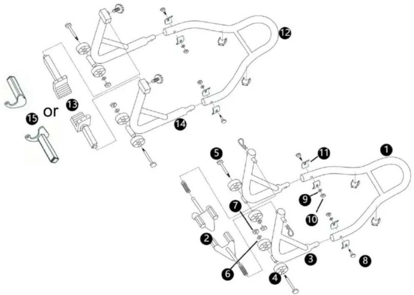
Prepare all the accessories and tools needed according to the parts I For the front wheel bracket:
Step 1: Insert Part 1 into 3, and then use Screws 8, 11, 9, and 1 tightly with tools.
Step 2: Install Parts 4, 5, 6, and 7 onto 3 in sequence, and lock 1 with tools.
Step 3: Insert Part 2 into 3, and then use the R-shaped part to fix The installation of the rear wheel bracket is the same as that of the wheel bracket. The difference is that you need to choose the appropriate plugs to use
PRODUCT DESCRIPTION
Assembling Instructions
A. Assemble the wheels on both sides of the frame and then insert frame pieces.
B. Place M8 screws through the holes of clamping pieces and the fr and make sure that the connecting part is covered with clamping pieces on both sides. Then add washers and use tools to tighten the lock - nuts.
C. Loosen the screws on both sides on the top of the frame with v insert the correct adaptors (paddle adaptors or fork adaptors) which can fit your motorcycle.
Operation Of the Stand With Paddle Adaptors
A. Loosen the screws on the top so that the position of adaptors can be adjusted.
B. Roll the stand and make sure your motorcycle rear wheel is in the middle of the frame.
C. Adjust the position of the paddle adaptors to match the width of motorcycle dual swing arm and then tighten the screw with plastic.
D. Raise the stand with the handle and move the stand to where it under the swing arm, then press down the stand in order to raise motorcycle rear wheel. Make sure the paddle adaptors are snug up against the swing arm.
Operation of the Stand with Fork Adaptors
E. Loosen the screws on the top so that the position of adaptors can be adjusted.
F. Roll the stand and make sure your motorcycle rear wheel is in the middle of the frame.
G. Adjust the position of the fork adaptors to match the width of your motorcycle bobbins on both sides and then tighten the screw with plastic.
H. Raise the stand with the round handle and move the stand to which fork adaptors are right under the bobbins, then press down the start order to raise your motorcycle rear wheel. Make sure the fork adams are snug up against the bobbins.
VEVOR®
TOUGH TOOLS, HALF PRICE
Technical Support and E-Warranty Certificate
www.vevor.com/support
VEVOR®
TOUGH TOOLS, HALF PRICE
natural_image
Two black metal chain linkages with attached small objects, no text or symbols visibleBESOIN D'AIDE? CONTACTEZ-NOUS!
PARAMÈTRES DU PRODUIT
natural_image
Two black metal chain linkages with attached clips, no text or symbols visiblewww.vevor.com/support
VEVOR®
TOUGH TOOLS, HALF PRICE
natural_image
Two black metal chain linkages with attached clips, no text or symbols visibleelettronica www.vevor.com/support
VEVOR®
TOUGH TOOLS, HALF PRICE
natural_image
Two black metal chain linkages with attached clips, no text or symbols visiblenatural_image
Two black metal chain linkages with attached clips, no text or symbols visiblePOTRZEBUJESZ POMOCY? SKONTAKTUJ SIĘ Z NAMI!
natural_image
Two black metal chain linkages with attached small objects, no text or symbols visibleBEHÖVER HJÄLP? KONTAKTA OSS!
www.vevor.com/support
VEVOR®
TOUGH TOOLS, HALF PRICE
Technische ondersteuning en e-garantiecertificaat www.vevor.com/support
DIRT BIKE STAND
MODEL: TD-003-05WFR
natural_image
Two black metal chain linkages with attached clips, no text or symbols visibleHULP NODIG? NEEM CONTACT MET ONS OP!
garantiecertificaat www.vevor.com/support