
PBS 350 C3 - Saw PARKSIDE - Free user manual and instructions
Find the device manual for free PBS 350 C3 PARKSIDE in PDF.

| Product type | Band saw |
| Brand | Parkside |
| Model | PBS 350 C3 |
| Power consumption (mode S1) | 350 W |
| Power consumption (mode S2 20 min) | 450 W |
| Rated voltage | 230-240 V ~ 50 Hz |
| No-load speed | 1400 min⁻¹ |
| Band speed | 900 m/min |
| Band length | 1400 mm |
| Band width (max.) | 12 mm |
| Max. cutting height | 80 mm |
| Max. throat depth | 200 mm |
| Saw table dimensions | 300 x 300 mm |
| Table tilt | 0° to 45° |
| Max. workpiece dimensions | 400 x 400 x 80 mm |
| Weight | Approx. 14.8 kg |
| Protection class | I |
| Protection rating | IPX0 |
| Sound pressure level (LpA) | 77.4 dB (K=3 dB) |
| Sound power level (LwA) | 90.4 dB (K=3 dB) |
| Vibrations (ah) | ≤ 2.5 m/s² |
| Intended use | Longitudinal and cross cutting of wood and similar materials |
| Safety | Safety switch on housing doors, anti-kickback protection, emergency stop |
| Maintenance | Regular cleaning, blade tension and adjustment, replacement of blade and table insert |
| Wear parts | Band saw blade (ref. 7901 502604), table insert (ref. 73220046) |
Frequently Asked Questions - PBS 350 C3 PARKSIDE
User questions about PBS 350 C3 PARKSIDE
0 question about this device. Answer the ones you know or ask your own.
Ask a new question about this device
Download the instructions for your Saw in PDF format for free! Find your manual PBS 350 C3 - PARKSIDE and take your electronic device back in hand. On this page are published all the documents necessary for the use of your device. PBS 350 C3 by PARKSIDE.
USER MANUAL PBS 350 C3 PARKSIDE
natural_image
Green industrial machine labeled 'PARKSIDE' with control panel and side-mounted mechanism (no readable text beyond label)
BAND SAW - PBS 350 C3
BANDSÄGE - PBS 350 C3
SCIE À RUBAN - PBS 350 C3

Band saw
Operating and Safety Instructions
Translation of the original operating instructions
WARNING: READ CAREFULLY BEFORE USE AND STORE SAFELY FOR FUTURE REFERENCE.

Scie à ruban
Before reading, unfold the page with the illustrations and then familiarise yourself with all the functions of the product.
DE AT CH
GB / IE / NI / CY / MT Operating and Safety Instructions Page 1
2
3
19
20
21
natural_image
Simple diagram with a numbered arrow pointing to a central square and a horizontal bar at the bottom (no text or symbols)B

4
natural_image
Technical line drawing of a mechanical device with internal components and mounting brackets (no text or symbols)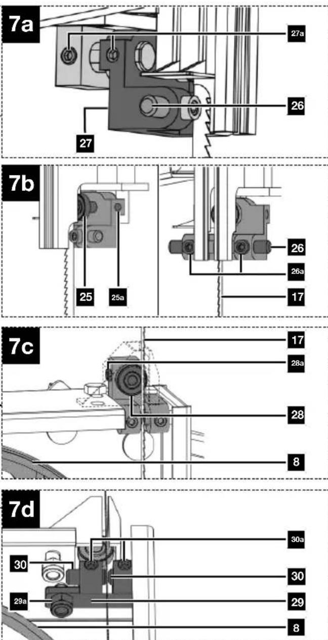

natural_image
Line drawing of a hand operating a 3D printer with a device labeled 'Parkside' (no text or symbols on the diagram itself)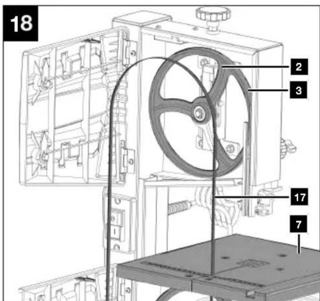
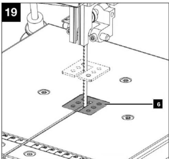
Table of contents
1 Explanation of the symbols on the product 2
2 Introduction.... 3
3 Product description (Fig. 1-19) 3
4 Scope of delivery (Fig. 1-3).... 3
5 Proper use.... 3
6 Safety instructions 4
7 Technical data.... 7
8 Unpacking.... 8
9 Assembly.... 8
10 Operation 11
11 Working instructions.... 12
12 Cleaning and maintenance 14
13 Transport.... 15
14 Storage.... 15
15 Electrical connection.... 15
16 Repair & ordering spare parts.... 15
17 Disposal and recycling.... 16
18 Troubleshooting.... 17
19 EU Declaration of Conformity 18
20 Warranty certificate.... 19
21 Exploded view.... 127
1 Explanation of the symbols on the product
Symbols are used in this manual to draw your attention to potential hazards. The safety symbols and the accompanying explanations must be fully understood. The warnings themselves will not rectify a hazard and cannot replace proper accident prevention measures.
 | Attention! Failure to observe the safety signs and warning information affixed to the product and failure to observe the safety and operating manual can result in serious injury or ev death. |
 | Before commissioning, read and observe the operating manual and safety instructions! |
 | Wear safety goggles. |
 | Wear hearing protection. |
 | If dust builds up, wear respiratory protection! |
 | Wear protective gloves! |
 | Always pull out the mains plug, before opening the housing doors. |
 | Attention! Pay attention to the running direction. |
 | Saw band width. |
| [BHAY] | Saw band length. |
| [WY90] | Only carry out maintenance, conversion, adjustment and cleaning work when the product is switched off and the mains plug is disconnected! |
 | The product complies with the applicable European directives. |
2 Introduction
Manufacturer:
Scheppach GmbH
Günzburger Straße 69
D-89335 Ichenhausen
Dear Customer
We hope your new product brings you much enjoyment and success.
Note:
In accordance with the applicable product liability laws, the manufacturer of this product assumes no liability for damage to the product or caused by the product arising from:
- Improper handling
• Non-compliance with the operating manual - Repairs carried out by third parties, unauthorised specialists
- Installing and replacing non-original spare parts
- Improper use
- Failures of the electrical system in the event of the electrical regulations and VDE provisions 0100, DIN 57113 / VDE0113 not being observed.
Note:
The operating manual is part of this product.
It includes important instructions for the safe, proper and economic operation of the product, for avoiding danger, for minimising repair costs and downtimes and for increasing the reliability and extending the service life of the product. In addition to the safety instructions in this operating manual, you must also observe the regulations applicable to the operation of the product in your country.
Familiarise yourself with all operating and safety instructions before using the product. Only operate the product as described and for the specified areas of application. Keep the operating manual in a good place and hand over all documents when passing the product on to third parties.
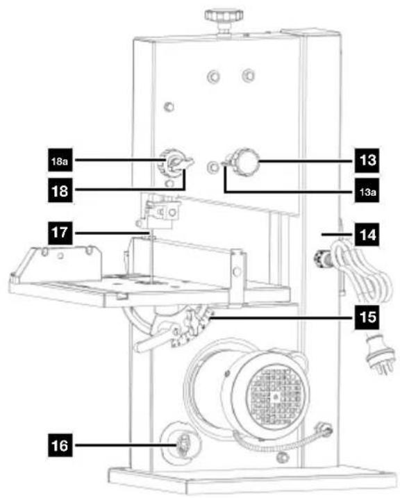
3 Product description (Fig. 1-19)
- Clamping screw
- Top band wheel
- Running surfaces (band saw blade)
- Band saw blade guard
- Top saw band guide
- Table inlay
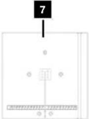
- Saw table
7a. U-reinforcement
7b. Knurled nut - Bottom band wheel
- Foot
- Door lock
- Housing doors
11a. Safety switch
12. On/off switch
13. Adjustment handle (top band wheel)
13a. Wing nut (top band wheel)
14. Main frame
15. Graduated scale (pivot range)
16. Suction port
17. Band saw blade
18. Wing screw (band saw blade guide)
18a. Adjusting nut (band saw blade guide)
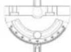
19. Transverse cutting gauge
19a. Knurled nut
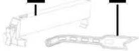
20. Parallel stop
20a. Clamping bar
21. Push stick
22. Wing nut
23. Locking handle
24. Clamping plate
25. Top support bearing
25a. Allen screw
26. Top guide pins
26a. Allen screws
27. Top retainer
27a. Allen screw (2x)
28. Bottom support bearing
28a. Allen screw
29. Bottom retainer
29a. Allen screw
30. Bottom guide pins
30a. Allen screws
31. End stop screw (saw table adjustment)
31a. Counternut (saw table adjustment)
32. Push rod retainer
4 Scope of delivery (Fig. 1-3)
Item Quantity Designation
7.1 x Saw table
-
1 x Band saw blade (pre-assembled)
-
1 x Mitre gauge
-
1 x Parallel stop
-
1 x Push stick
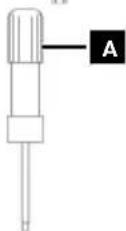
A. 1 x Slotted-head screwdriver
B. 1 x Open-ended spanner, size 10/13
C. 1 x Allen key, 3 mm
D. 1 x Allen key, 4 mm
E. 1 x Allen key, 5 mm
1 x Band saw
1 x Operating manual
5 Proper use
The band saw is used for the longitudinal and transverse cutting of timbers or wood-like workpieces. Round materials may only be cut using suitable holding devices.

WARNING
Do not use the product to cut materials other than those described in the operating manual.

WARNING
The supplied band saw blade is only intended for the sawing of wood! Do not use this blade for sawing firewood!
The product may only be used in the intended manner. Any use beyond this is improper. The user/operator, not the manufacturer, is responsible for damages or injuries of any type resulting from this.
Only suitable band saw blades may be used for the product.
An element of the intended use is also the observance of the safety instructions, as well as the assembly instructions and operating information in the operating manual.
Persons who operate and maintain the product must be familiar with the manual and must be informed about potential dangers.
The liability of the manufacturer and resulting damages are excluded in the event of modifications of the product.
Please note that our products were not designed with the intention of use for commercial or industrial purposes. We assume no guarantee if the product is used in commercial or industrial applications, or for equivalent work.
Explanation of the signal words in the operating manual

DANGER
Signal word to indicate an imminently hazardous situation which, if not avoided, will result in death or serious injury.

WARNING
Signal word to indicate a potentially hazardous situation which, if not avoided, could result in death or serious injury.

CAUTION
Signal word to indicate a potentially hazardous situation which, if not avoided, could result in minor or moderate injury.
ATTENTION
Signal word to indicate a potentially hazardous situation which, if not avoided, could result in product or property damage.
6 Safety instructions
General power tool safety warnings
Save all warnings and instructions for future reference.
The term “power tool” in the warnings refers to your mains-operated (corded) power tool or battery-operated (cordless) power tool.

WARNING
Read all safety warnings, instructions, illustrations and specifications provided with this power tool.
Failure to follow all instructions listed below may result in electric shock, fire and/or serious injury.
1) Work area safety
a) Keep your work area clean and well-lit. Cluttered or dark areas invite accidents.
b) Do not operate power tools in explosive atmospheres, such as in the presence of flammable liquids, gases or dust. Power tools create sparks which may ignite the dust or fumes.
c) Keep children and bystanders away while operating a power tool. Distractions can cause you to lose control.
2) Electrical safety
a) The connection plug of the electric tool must fit into the socket. Never modify the plug in any way. Do not use any adapter plugs with earthed (grounded) power tools. Unmodified plugs and matching outlets will reduce risk of electric shock.
b) Avoid body contact with earthed or grounded surfaces, such as pipes, radiators, ranges and refrigerators. There is an increased risk of electric shock if your body is earthed or grounded.
c) Do not expose power tools to rain or wet conditions. Water entering a power tool will increase the risk of electric shock.
d) Do not abuse the cord. Never use the cord for carrying, pulling or unplugging the power tool. Keep cord away from heat, oil, sharp edges or moving parts. Damaged or entangled cords increase the risk of electric shock.
e) When operating a power tool outdoors, use an extension cord suitable for outdoor use. Use of a cord suitable for outdoor use reduces the risk of electric shock.
f) If operating a power tool in a damp location is unavoidable, use a residual current device (RCD) protected supply. Use of an RCD reduces the risk of electric shock.
3) Personal safety
a) Stay alert, watch what you are doing and use common sense when operating a power tool. Do not use a power tool while you are tired or under the influence of drugs, alcohol or medication. A moment of inattention while operating power tools may result in serious personal injury.
b) Wear personal protective equipment and always safety goggles. Protective equipment such as a dust mask, non-skid safety shoes, safety helmet or hearing protection used for appropriate conditions will reduce personal injuries.
c) Prevent unintentional starting. Ensure the switch is in the off-position before connecting to power source and/or rechargeable battery, picking up or carrying the tool. Carrying power tools with your finger on the switch or energising power tools that have the switch on invites accidents.
d) Remove any adjusting tools or spanners/keys before turning the power tool on. A wrench or a key left attached to a rotating part of the power tool may result in personal injury.
e) Avoid abnormal postures. Keep proper footing and balance at all times. This enables better control of the power tool in unexpected situations.
f) Wear suitable clothing. Do not wear loose clothing or jewellery. Keep your hair and clothing away from moving parts. Loose clothes, jewellery or long hair can be caught in moving parts.
g) If devices are provided for the connection of dust extraction and collection facilities, ensure these are connected and properly used. Use of dust extraction can reduce dust-related hazards.
h) Do not let familiarity gained from frequent use of tools allow you to become complacent and ignore tool safety principles. A careless action can cause severe injury within a fraction of a second.
4) Power tool use and care
a) Do not force the power tool. Use the correct power tool for your application. The correct power tool will do the job better and safer at the rate for which it was designed.
b) Do not use the power tool if the switch does not turn it on and off. Any power tool that cannot be controlled with the switch is dangerous and must be repaired.
c) Disconnect the plug from the power source and/or remove the battery pack, if detachable, from the power tool before making any adjustments, changing accessories, or storing power tools. Such precautionary measures reduce the risk of starting the power tool accidentally.
d) Store idle power tools out of the reach of children and do not allow persons unfamiliar with the power tool or these instructions to operate the power tool. Power tools are dangerous in the hands of untrained users.
e) Maintain power tools and attachments. Check for misalignment or binding of moving parts, breakage of parts and any other condition that may affect the power tool's operation. If damaged, have the power tool repaired before use. Many accidents are caused by poorly maintained power tools.
f) Keep cutting tools sharp and clean. Properly maintained cutting tools with sharp cutting edges are less likely to bind and are easier to control.
g) Use electric tools, insertion tools, etc. according to these instructions. Take into account the working conditions and the work to be performed. Use of the power tool for operations different from those intended could result in a hazardous situation.
h) Keep handles and grasping surfaces dry, clean and free from oil and grease. Slippery handles and grasping surfaces do not allow for safe handling and control of the tool in unexpected situations.
5) Service
a) Only have your power tool repaired by qualified specialists and only with original spare parts. This will ensure that the safety of the power tool is maintained.
6.1 Safety instructions for band saws
a) Do not use damaged or deformed saw blades.
Damaged or deformed saw blades could break and/or bend.
b) Do not use coolant fluids. The use of water or other coolants can cause electric shock.
c) Operate the band saw at the appropriate speed for the permissible applications and materials. Working at an improper speed for the material being cut can lead to saw blade breakage and bodily injury.
d) Do not operate the power tool with the access cover to the saw blade open. Contact with moving parts can cause bodily injury.
6.2 Additional safety instructions

WARNING
Tool attachments may be sharp and become hot during use. Always wear protective gloves when handling the tool attachments.
- When cutting round or irregular shaped wood, use a device to secure the workpiece and prevent it turning.
- When cutting boards on edge, use a device to prevent the workpiece kicking back.
- If devices are provided for the connection of dust extraction and collection facilities, ensure these are connected and properly used. Use of dust extraction can reduce dust-related hazards.
- The product may only be operated by people who are familiar with handling it.

WARNING
The supplied band saw blade is only intended for the sawing of wood! Do not use this blade for sawing firewood!
- Before commissioning, ensure that the mains voltage matches with the operating voltage on the type plate.
- Long supply cables, extensions, cable reels, etc. cause a drop in voltage and can impede motor start-up.
- Keep children and other people away while using the product. Distractions may cause you to lose control of the product.
- Observe the direction of rotation of the motor and saw band.
- Never operate the product with defective Protective devices or without safety devices.
- Do not process workpieces that are too small in order to keep them secure in your hands.

WARNING
Danger of injury!
If you remove blockages with your bare hands, you may injure yourself.
- Wear protective gloves.
-
Use suitable tools (e.g. a wooden stick).
-
Set the adjustable guards such that they are as close as possible to the workpiece.
- Protective covers must not be used for transport or improper operation of the product.

WARNING
Do not use damaged or deformed tool attachments.

WARNING
Make sure that the tool attachment is suitable for the material to be processed.

WARNING
With a damaged table inlay there is a risk of small parts jamming between table inlay and saw blade, blocking the saw blade.
Immediately replace damaged table inlays!

WARNING
There is a risk of accident! Always carry out cleaning work when the product is switched off. There is a danger of injury! Let the product cool down before cleaning. Elements of the engine are hot. There is a danger of injury and burning!
The product can start unexpectedly and cause injuries.
- Switch off the product before all cleaning work.
- Allow the engine to cool down.
ATTENTION
The teeth of the band saw blade must point downwards.
- Do not use the product if it is damaged. Never remove protective devices from the product. This can result in serious injuries.
- For mitre cuts with an inclined saw table, the parallel stop should be placed on the lower part of the saw table.
ATTENTION
Secure long workpieces against tipping at the end of the cutting process (e.g. with a roller stand or similar).
- Keep your hands at a safe distance from the band saw blade. Use a push stick for narrow cuts.
- Store the push stick on the holder provided for it on the product so that you can reach it from your normal working position and always have it to hand.
- Switch the product off if it is not in use.
- In the normal working position, the operator is in front of the product.
Residual risks
The product has been built according to state-of-the-art and the recognised technical safety rules. However, individual residual risks can arise during operation.
- Residual risks can be minimised if the "Safety Instructions" and the "Intended Use" together with the operating manual as a whole are observed.
- Use the product in the way that is recommended in this operating manual. This is how to ensure that your product provides optimum performance.
- Furthermore, despite all precautions having been met, some non-obvious residual risks may still remain.
- Keep your hands away from the working area when the product is in operation.
- Damage to hearing if the stipulated hearing protection is not worn.
- Damage to the lungs if the stipulated respiratory protection is not worn.
- Risk of injury from tools thrown away due to improper holding or guiding.
- Health hazard due to electrical power, with the use of improper electrical connection cables.
- Avoid accidental start-up of the product: when inserting the plug into the socket, do not press the on/off switch.
- Before performing setting or maintenance work, release the on/off switch and pull out the mains plug.

WARNING
This power tool generates an electromagnetic field during operation. This field can impair active or passive medical implants under certain circumstances. In order to prevent the risk of serious or deadly injuries, we recommend that persons with medical implants consult with their physician and the manufacturer of the medical implant prior to operating the power tool.

WARNING
In case of extended working periods, the operating personnel may suffer circulatory disturbances in their hands (vibration white finger) due to vibrations.
Raynaud's syndrome is a vascular disease that causes the small blood vessels on the fingers and toes to cramp in spasms. The affected areas are no longer supplied with sufficient blood and therefore appear extremely pale. The frequent use of vibrating products can cause nerve damage in people whose circulation is impaired (e.g. smokers, diabetics).
If you notice unusual adverse effects, stop working immediately and seek medical advice.
7 Technical data
| Rated voltage 230 - 240 V~ 50 Hz | |
| Power consumption 350 Watt (S1*) | |
| 450 Watt (S2 20min**) | |
| Idle speed n_0 | 1400 rpm |
| Saw band length 1400 mm | |
| Saw band width 6 mm | |
| Max. band saw blade width 12 mm | |
| Band saw blade speed 900 m/min | |
| Cut height 0 - 80 mm | |
| Swing 200 mm | |
| Saw table size 300 x 300 mm | |
| Inclinable saw table | 0° - 45° |
| Max. workpiece size | 400 x 400 x 80 mm |
| Protection class | I |
| Protection category | IPX0 |
| Weight | approx. 14.8 kg |
Subject to technical changes!
\*Operating mode S1 (continuous operation)
The product can be operated continuously with the specified power.
\*\*Operating mode S2 (short-term operation)
The product may only be operated at the specified power for a brief time (20 min.).
The workpiece must have a minimum height of 3 mm and a minimum width of 10 mm.
Noise data

WARNING
Noise can have serious effects on your health. If the machine noise exceeds 85 dB, please wear suitable hearing protection for you and persons in the vicinity.
The noise and vibration values have been determined in accordance with EN 62841.
| Sound pressure level L_pA | 77.4 dB |
| Uncertainty K_pA | 3 dB |
| Sound power level L_wA | 90.4 dB |
| Uncertainty K_wA | 3 dB |
| Vibration ah | ≤ 2.5 m/s^2 |
The specified noise emission values have been measured in accordance with a standardised test procedure and can be used to compare one power tool with another.
The specified device emissions values can also be used for an initial estimation of the load.

WARNING
The noise emission values can vary from the specified values during the actual use of the power tool, depending on the type and the manner in which the electric tool is used, and in particular the type of workpiece being processed.
Try to keep the stress as low as possible. For example: Limit working time. In doing so, all parts of the operating cycle must be taken into account (such as times in which the power tool is switched off or times in which it is switched on, but is not running under a load).
8 Unpacking

WARNING
The product and the packaging material are not children's toys!
Do not let children play with plastic bags, films or small parts! There is a danger of choking or suffocating!
- Open the packaging and carefully remove the product.
- Remove the packaging material, as well as the packaging and transport safety devices (if present).
- Check whether the scope of delivery is complete.
- Check the product and accessory parts for transport damage. Immediately report any damage to the transport company that delivered the Product. Later claims will not be recognised.
- If possible, keep the packaging until the expiry of the warranty period.
- Familiarise yourself with the product by means of the operating manual before using for the first time.
- With accessories as well as wearing parts and replacement parts use only original parts. Spare parts can be obtained from your specialist dealer.
- When ordering please provide our article number as well as type and year of manufacture for the product.
9 Assembly
ATTENTION
Always make sure the product is fully assembled before commissioning!

WARNING
Pull out the mains plug before carrying out any setting, servicing or repair work!
Tool required:
- Slotted screwdriver* (A)
- 1x open-ended spanner, AF 10/13 ~mm^* (B)
- 1 x Allen key 3mm^* (C)
- 1 x Allen key 4 mm* (D)
- 1 x Allen key 5 mm* (E)
* = may not be included in the scope of delivery!
9.1 Assembling the saw table (7) (Fig. 4-6)
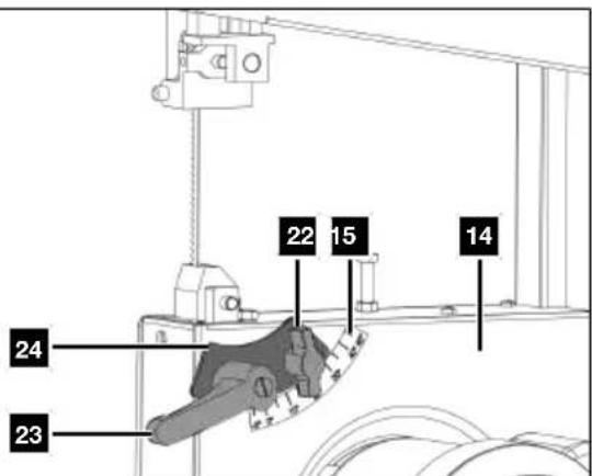
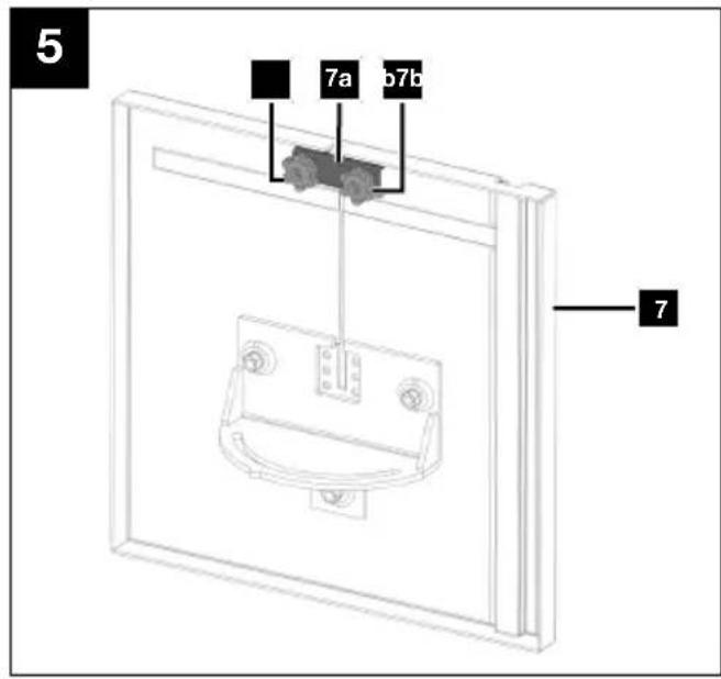
- Remove the wing nut (22), the locking handle (23), the two washers and the clamping plate (24).
- Then remove the two knurled nuts (7b), the U-reinforcement (7a) and the two countersunk screws M6x18 from the saw table (7). Use the 4 mm Allen key (D).
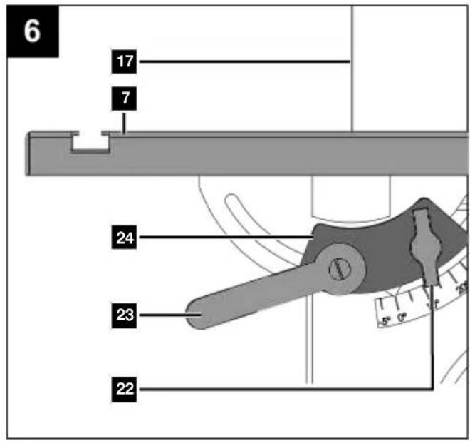
- Guide the saw table (7) over the band saw blade (17). Fasten it to the two screws on the frame (14) with the clamping plate (24), the two washers, the locking handle (23) and the wing nut (22).
- Mount the U-reinforcement (7a) to the bottom of the saw table (7) with two countersunk screws M6x18 and two knurled nuts (7b). Use the 4 mm Allen key (D).
9.2 Which band saw blade to use
Check that the tool attachment is fitted securely.
Tool attachments that are not fitted correctly or securely may come loose during operation and injure you.
The band saw blade included in the scope of delivery is intended for universal use. The following criteria should be considered when selecting the band saw blade:
- It is possible to cut tighter radii with a narrow band saw blade than with a wide band saw blade.
- Use wide band saw blades to perform straight cuts. This is important in particular when cutting wood. The band saw blade has a tendency to follow the wood grain and therefore deviates easily from the desired position.
- Fine-toothed band saw blades cut more smoothly, but also more slowly than coarse band saw blades.
- Only use undamaged band saw blades that are in perfect condition. Band saw blades that are bent, blunt or damaged in any other way can break.
9.3 Tensioning the band saw blade (17) (Figs. 1, 2)
ATTENTION
If the band saw is at a standstill for an extended period, the band saw blade tension must be relieved, i.e. before switching the band saw on it is necessary to check the band saw blade tension.
- To tension the band saw blade (17), turn the clamping screw (1) clockwise.
Notes:
- The correct tension of the band saw blade can be determined by pressing the finger laterally against the band saw blade, roughly centrally between the two band wheels (2+8). The band saw blade should only depress slightly (approx. 1-2 mm) here.
- The sufficiently tensioned band saw blade makes a metallic sound when tapped.
- Relieve the band saw blade tension if it is not in use for an extended time, so that it does not become overstretched.
ATTENTION
With high tension, the band saw blade may break.
ATTENTION
Danger of injury!
If the tension is too low, the driven band wheel may spin, resulting in the band saw blade coming to a standstill.
- To relieve the band saw blade (17), turn the clamping screw (1) anti-clockwise.
9.4 Adjust the band saw blade (17) (Fig. 1, 2)
ATTENTION
Before it is possible to implement the band saw blade setting, the band saw blade must be tensioned correctly.
- Open the housing doors (11) by loosening the door lock (10). Use the slotted screwdriver (A).
- Turn the top band wheel (2) clockwise slowly. The band saw blade (17) must run in the centre on the running surfaces (3) of the top band wheel (2). If this is not the case, correct the angle of the top band wheel (2).
-
To do this, open the wing nuts (13a).
-
If the band saw blade (17) runs more towards the rear edge of the band wheel (2), then the adjustment handle (13) must be rotated anticlockwise.
-
If the band saw blade (17) runs more towards the front edge of the band wheel (2), then the adjustment handle (13) must be rotated clockwise.
-
After setting the top band wheel (2), check the position of the band saw blade (17) on the bottom band wheel (8).
- Turn the bottom band wheel (8) slowly by hand to check the position of the band saw blade (17).
- The band saw blade (17) should be positioned in the centre on the running surfaces (3) of the bottom band wheel (8). If this is not the case, the angle of the top band wheel (2) must be adjusted again.
- To ensure that the adjustment of the top band wheel (2) influences the position of the band saw blade (17) on the bottom band wheel (8), turn the bottom band wheel (8) several times.
- Retighten the wing nut (13a).
- After successful adjustment, close the housing doors (11) again and secure the door locks (10). Use the slotted screwdriver (A).
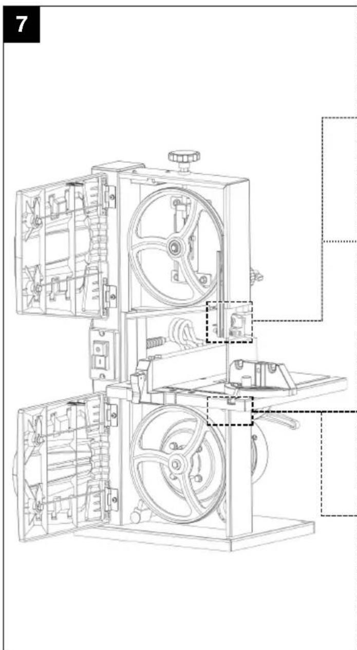
9.5 Adjusting the band saw blade guide (Fig. 1, 7)
Both the support bearing (25+28) and the guide pins (26+30) must be readjusted before initial commissioning and after every band saw blade change.
- Open the housing doors (11) by loosening the door lock (10). Use the slotted screwdriver (A).
9.5.1 Adjusting the top guide pins (26) (Figs. 1, 7a, 7b)
- Loosen the Allen screws (27a) of the top retainer (27). Use the 3 mm Allen key (C).
- Move the top retainer (27) until the front edge of the guide pins (26) is approx. 1mm behind the tooth base of the band saw blade (17).
- Retighten the Allen screws (27a) of the top retainer (27). Use the 3 mm Allen key (C).
ATTENTION
The band saw blade will be unusable if the teeth touch the running band saw blade.
- Loosen the Allen screws (26a) of the top guide pins (26). Use the 3 mm Allen key (C).
- Slide the top guide pins (26) in the direction of the band saw blade (17)!
ATTENTION
The distance between the guide pins and band saw blade must not exceed 0.5 mm. (Band saw blade must not jam).
- Retighten the Allen screws (26a) of the top guide pins (26). Use the 3 mm Allen key (C).
- Turn the top band wheel (2) clockwise a few times.
- Check the setting of the top guide pins (26) again and readjust if necessary.
- If necessary, adjust the top support bearing (25) (see 9.5.2).
9.5.2 Top support bearing (25) (Fig. 7b)
- Loosen the Allen screw (25a) of the top support bearing (25). Use the 3 mm Allen key (C).
- Move top support bearing (25) until it no longer touches the band saw blade (17) (max. distance 0.5mm).
- Retighten the Allen screw (25a) of the top support bearing (25). Use the 3 mm Allen key (C).
9.5.3 Adjusting the bottom retainer (29) (Fig. 1, 7d)
- Set the saw table (7) at a 45^ angle.
- Open the housing doors (11) by loosening the door lock (10). Use the slotted screwdriver (A).
- Loosen the Allen screw (29a) of the bottom retainer (29). Use the 5 mm Allen key (E) and the open-ended spanner, size 10/13 (B).
- Move the bottom retainer (29) until the front edge of the bottom guide pins (30) is approx. 1mm behind the tooth base of the band saw blade (17).
- Retighten the Allen screw (29a) of the bottom retainer (29). Use the 5 mm Allen key (E) and the open-ended spanner, size 10/13 (B).
- Continue in accordance with the instructions in the section 9.5.4.
9.5.4 Adjusting the bottom support bearing (Fig. 1, 7c)
- Loosen the Allen screw (28a) of the support bearing (28). Use the 3 mm Allen key (C).
- Move the bottom support bearing (28) until it no longer touches the band saw blade (17) (max. distance 0.5mm).
- Retighten the Allen screw (28a) of the bottom support bearing (28). Use the 3 mm Allen key (C).
- Continue in accordance with the instructions in the section 9.5.5.
9.5.5 Adjusting the bottom guide pins (30) (Fig. 1, 7d)
ATTENTION
The band saw blade will be unusable if the teeth touch the running band saw blade.
- Loosen the Allen screws (30a) of the bottom guide pins (30). Use the 3 mm Allen key (C).
- Slide the guide pins (30) in the direction of the band saw blade (17).
ATTENTION
The distance between the guide pins and band saw blade must not exceed 0.5 mm. (Band saw blade must not jam).
- Retighten the two Allen screws (30a) of the bottom guide pins (30). Use the 3 mm Allen key (C).
- Turn the bottom band wheel (8) clockwise a few times.
- Check the setting of the bottom guide pins (30) again and readjust if necessary.
- If necessary, adjust the bottom support bearing (28) as described in 9.5.4.
- After successful adjustment, close the housing doors (11) again and secure the door locks (10). Use the slotted screwdriver (A).
9.6 Adjusting the top band saw blade guide (5) (Fig. 8)
Note:
Check the setting before every cutting process and adjust if necessary.
- Loosen the wing screw (18).
- Lower the top band saw blade guide (5) as close as possible (distance approx. 2-3 mm) to the workpiece to be processed by turning the adjusting nut (18a).
- Retighten the wing screw (18).
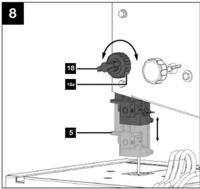
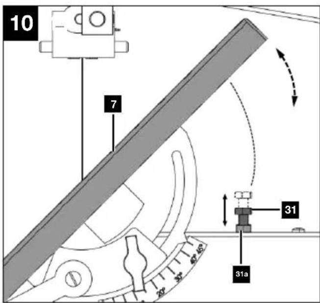
9.7 Adjusting the saw table (7) to 90° (Fig. 9, 10)
- Adjust the saw table (7) horizontal to 90°.
- This setting is predefined by the end stop screw (31).
- Check the end stop screw (31) and the counternut (31a) for firm seating and tighten if necessary. Use the open-ended spanner AF 10/13 (B).
-
If the saw table (7) is not adjusted at a right-angle to the saw blade (17), the end stop screw (31) must be readjusted.
-
Loosen the end stop screw (31) and the counternut (31a). Use the open-ended spanner AF 10/13 (B).
- Turn the end stop screw (31) clockwise to lower the end stop point or anti-clockwise to increase it.
- Using an angle*, align the saw table (7) at a right-angle to the band saw blade (17), put the end stop screw (31) in the desired position and tighten the counternut (31a) again. Use the open-ended spanner AF 10/13 (B).
* = may not be included in the scope of delivery!
9.8 Use as a stationary machine (Fig. 1)
The product must be mounted on a workbench for continuous use.
- The product must be securely installed, i.e. bolted down on a workbench or fixed machine stand.
-
There are fixing holes in the foot (9) for this purpose.
-
Mark the drill holes.
-
Place the product as it will be installed later.
-
Mark the positions of the holes to be drilled on the workbench.
These are predetermined by the holes in the foot (9).
Installation close to the edge is recommended. -
Drill the holes (at least 6.5 mm diameter) through the workbench.
- Place the product over the drilled holes congruent with the holes in the foot (9) and insert suitable screws* through the holes from above and tighten them.
* = may not be included in the scope of delivery!
9.9 Extraction port set (16) (Fig. 2)
The product is equipped with an extraction port.
The extraction port set (16) has a diameter of 40 mm.
Connect a dust extractor when processing dusty materials.
ATTENTION
The dust extraction system must be suitable for the material to be processed.
Use a special extraction device to extract particularly harmful or carcinogenic dusts.
- Connect the hose of a suitable dust extraction system* (e.g. industrial hoover) directly to the extraction port set (16).
* = may not be included in the scope of delivery!
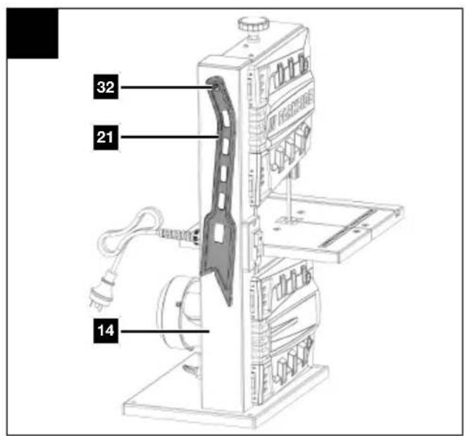
9.10 Push rod retainer (32) (Fig. 11)
The push rod retainer (32) is pre-mounted on the frame (14).
If unused, the push rod (21) must always be stowed in the push stick retainer (32).
10 Operation
ATTENTION
Always make sure the product is fully assembled before commissioning!
Note:
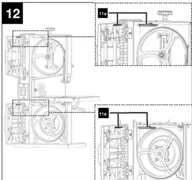
The product is equipped with a safety switch. This means that the product cannot be switched on if the doors are open or have not been closed properly.
Make sure that both safety switches (11a) engage properly on the housing doors (11).

WARNING
Danger of injury!
The on/off switch and the safety switch must not be locked!
- Do not work with the product if the switches are damaged.
- Make sure the product is in working order before each use.

WARNING
Always make sure that the tool attachment is fitted correctly!

WARNING
Make sure that the tool attachment is suitable for the material to be processed.
Note:
The product must be mounted on a workbench for continuous use.
- Let the tool attachment reach full speed before processing the workpiece.
- Select a tool attachment that corresponds to the material to be processed.
- The saw table must be mounted correctly.
- Place the product in a stable location.
-
Prior to commissioning, all covers and safety devices must be mounted correctly. Damaged or illegible stickers must be replaced.
-
Check whether the moving parts function faultlessly and do not jam or whether parts are damaged. All parts must be correctly mounted and all conditions must be fulfilled to ensure fault-free operation of the power tool.
- In case of previously machined wood, be aware of any foreign bodies, such as nails or screws, etc.
- Follow the running direction of the tool attachment.
10.1 Switching the product on/off (fig. 1, 12)
Make sure that both safety switches (11a) engage properly on the housing doors (11).
Switching on
- Insert the mains plug into a properly fused mains socket.
- Push the ON/OFF switch (12), which is marked "I", to switch the product on.
Switching off
- Push the ON/OFF switch (12), which is marked "0", to switch the product off.
- Pull the mains plug out of the socket when the product is not in use.
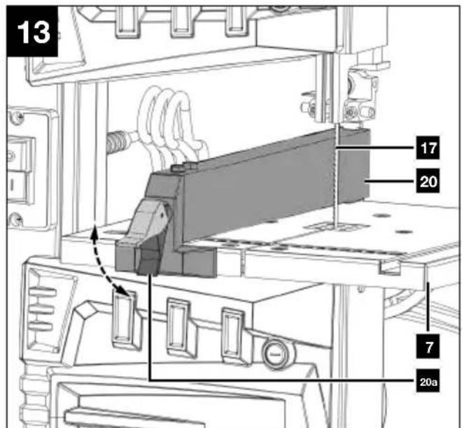
10.2 Parallel stop (20) (Fig. 13)
Note:
The parallel stop can be fitted to the right of the band saw blade.
- Push the clamping bar (20a) of the parallel stop (20) up.
- First place the parallel stop (20) on the rear of the saw table (7) and then push the parallel stop (20) down.
- Move the parallel stop (20) and adjust it to the desired dimension.
- Push the clamping bar (20a) down to fix the parallel stop (20) in place. In order to increase the clamping force of the clamping bar (20a), rotate it clockwise until the parallel stop (20) is sufficiently fixed in place.
- Make sure that the parallel stop (20) always runs parallel to the band saw blade (17).
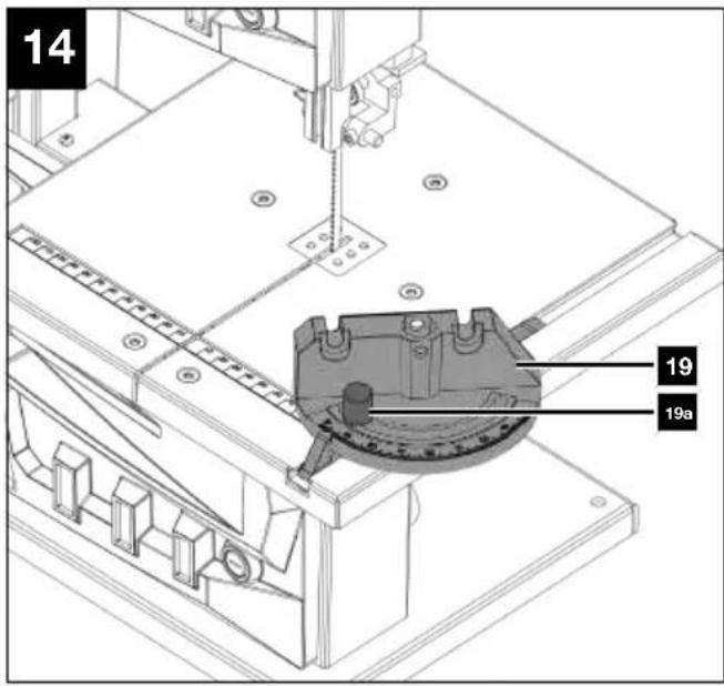
10.3 Mitre gauge (19) (Fig. 1, 14)
- Insert the mitre gauge (19) into the groove of the saw table (7).
- Loosen the knurled nut (19a).
- Turn the mitre gauge (19) until the desired angle has been set. The arrow on the mitre gauge (19) indicates the set angle.
- Retighten the knurled nut (19a).
10.4 Angled cuts (Figs. 1, 14, 15)
In order to execute angled cuts parallel to the band saw blade (17), it is possible to tilt the saw table (7) from 0° to 45°.
- Undo the wing nut (22) and locking handle (23).
- Tilt saw table (7) forwards, until the desired angle is set on the degree scale (15).
- Tighten the wing nut (22) and the locking handle (23).
ATTENTION
With a tilted saw table, the parallel stop must always be fitted to the right of the band saw blade. This prevents the workpiece from slipping.
11 Working instructions
The following safe working methods are considered to contribute to safety but may not be appropriate, fully or extensively applicable for every use. They cannot cover all possible hazardous conditions and must be interpreted carefully.
- Risk to health from wood dust or wood chippings. It is essential that personal protective equipment, such as eye protection, is worn. Use a chip extraction system!
- If the product is not in operation, e.g. work is complete, you should slacken the band saw blade. Attach a corresponding note to the product for the next user about the tensioning of the band saw blade.
- Store unused band saw blades together and safely in a dry place. Check for faults, such as teeth or cracks, before use. Do not use defective band saw blades!

WARNING
Tool attachments may be sharp and become hot during use. Always wear protective gloves when handling the tool attachments.
- Check the covers and protective devices for damage and correct seating. Replace them if necessary.
- Wear hearing protection and safety goggles during the entire operating period.
- Dress properly. Do not wear loose clothing or jewellery. Keep your hair and clothing away from moving parts. Loose clothes, jewellery or long hair can be caught in moving parts.
- Always position the band saw blade guide as close as possible to the workpiece when working.
-
Only work in daylight or with good, artificial lighting.
-
Always use the parallel stop for straight cuts in order to prevent the workpiece from tilting or slipping.
- Keep your hands at a safe distance from the band saw blade. Use a push stick for narrow cuts.
- For angled cuts, move the saw table into the appropriate position and guide the workpiece on the parallel stop.
- To cut dovetail-shaped tines, pins or wedges, put the saw table into the corresponding position on the angle scale.
- For curved and irregular cuts, you should guide the workpiece using both hands, push your closed fingers evenly. Hold the workpiece with your hands in a safe area.
- For repeated cutting of curve and irregular cuts, it is recommended to use an auxiliary template.
- When cutting round or irregular shaped wood, use a device to secure the workpiece and prevent it turning.
Note:
Before the first work and after each tool attachment change, carry out a test run without load. Switch off the product immediately if the tool attachment runs out of round, there is considerable vibration or abnormal noises are heard.
- Always position the band saw blade guide as close as possible to the workpiece when working.
- The workpiece must always be guided with both hands and kept flat against the saw table. This prevents the band saw blade from jamming.
- It is recommended to perform a cut in a single working step instead of dividing it into several sections, which may require the workpiece to be pulled back. However if pulling the workpiece back is unavoidable, the band saw should be switched off beforehand. The workpiece should only be pulled back once the band saw blade has come to a complete standstill.
- When sawing, the workpiece must always be guided by its longest side.
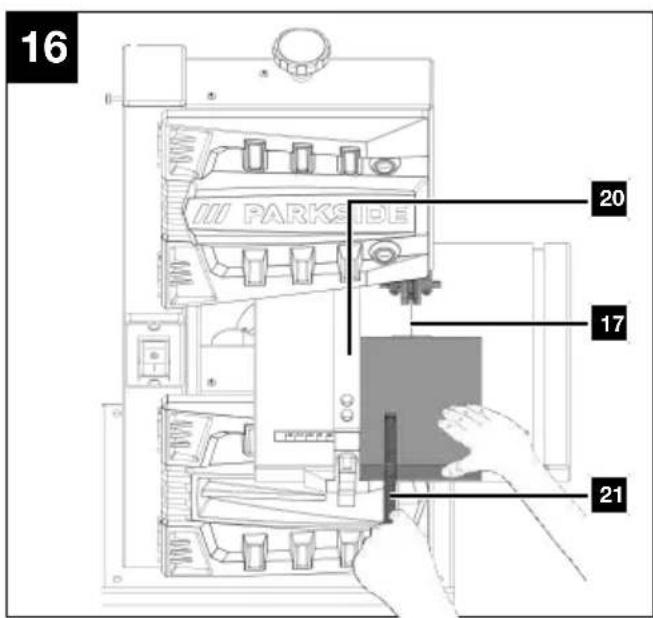
11.1 Performing longitudinal cuts (Fig. 1, 16)
Sawing along the wood fibre is referred to as a longitudinal cut. You can cut freehand along a marked out line or along the parallel stop to achieve a better result.
For right-angled cuts (saw table is at a right-angle to the band), the parallel stop is positioned to the left of the band saw blade so that the workpiece can be guided safely along the stop with the right hand.
ATTENTION
Secure long workpieces against tipping at the end of the cutting process (e.g. with a roller stand or similar).
- Adjust the parallel stop (20) as described in 10.2.
- Lower the saw band guide (5) onto the workpiece (see 9.6).
- Switch on the saw as described under 10.1.
- Place your hands flat on the workpiece with your fingers closed and slide it along the parallel stop (20) into the band saw blade (17).
- Always slide the workpiece at a steady rate long the parallel stop up to the end using a push stick (21).
11.2 Performing cross cuts (Fig. 1, 14)
Cross cut refers to sawing at a right-angle to the fibre of the wood. Even this type of cutting can be performed free-hand, but it is recommended to use a mitre gauge for safety and accuracy. The mitre gauge can be adjusted for mitre cuts up to 45^ . In combination with an inclined saw table, double mitre cuts can also be made.
- Insert the mitre gauge (19) as described in 10.3.
- Hold the workpiece firmly against the stop of the mitre gauge (19) and flat on the saw table (7).

WARNING
Pay attention to your fingers, especially towards the end of the cut and maintain your distance from the tool attachment.
11.3 Performing angled cuts (Fig. 1, 15)
For mitre cuts with an angled saw table, the parallel stop must be positioned on the downward facing side to the right of the band saw blade (if the workpiece width allows this), in order to secure the workpiece against slipping.
- Adjust the saw table (7) to the desired angle (see 10.4).
- Make the cut as described under 11.1.
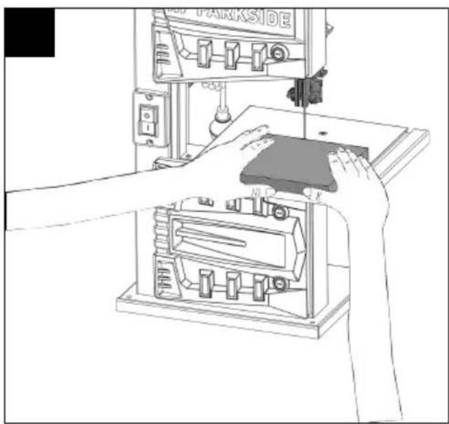
11.4 Freehand cuts (Fig. 1, 17)
One of the most important features of a band saw is the ease with which it can cut curves and radii.
- Lower the saw band guide (5) onto the workpiece (see 9.6).
- Switch on the saw as described under 10.1.
- Press the workpiece firmly on the saw table (7) and slide it slowly into the band saw blade (17). In many cases it is helpful to roughly saw curves and corners approximately 6 mm from the line.
- If it is necessary to saw curves that are too tight for the band saw blade used, auxiliary cuts must be sawn up to the front face of the curve. The final radius can be subsequently sawn out.
12 Cleaning and maintenance

WARNING
Pull out the mains plug before carrying out any setting, servicing or repair work!
12.1 Cleaning

WARNING
There is a risk of accident! Always carry out cleaning work when the product is switched off. There is a danger of injury! Let the product cool down before cleaning. Elements of the engine are hot. There is a danger of injury and burning!
The product can start unexpectedly and cause injuries.
- Switch off the product before all cleaning work.
-
Allow the engine to cool down.
-
Keep protective devices, air vents and the motor housing as free of dust and dirt as possible. Rub the product clean with a clean cloth* or blow it off with compressed air* at low pressure. We recommend that you clean the product directly after every use.
- Do not clean the tool attachment while it is still in operation.
- Never clean the band saw blade or the band saw blade guide with a hand-held brush or scraper if the band saw blade is running. Resinous band saw blades jeopardise work safety and must be cleaned regularly.
- Keep handles and grasping surfaces dry, clean and free from oil and grease. Slippery handles and grasping surfaces do not allow for safe handling and control of the tool in unexpected situations.
- We recommend that you clean the product directly after every use.
- Clean the product at regular intervals using a damp cloth* and a little soft soap. Do not use any cleaning products or solvents; they could attack the plastic parts of the product. Make sure that no water can penetrate the product interior.
12.2 Maintenance

WARNING
Have maintenance and repair tasks that are not described in this operating manual, carried out by a specialist workshop. Use only original spare parts.
There is a risk of accident! Always carry out maintenance and cleaning work with the motor switched off and the mains plug disconnected. There is a danger of injury! Let the Product cool down before all maintenance and cleaning tasks. Elements of the engine are hot. There is a danger of injury and burning!
The product can start unexpectedly and cause injuries.
- Switch off the product before all cleaning and maintenance work.
- Allow the product to cool down.
- Disconnect the mains plug!
12.2.1 Changing the saw band (17) (Figs. 1, 5, 18)
- Adjust the top band saw blade guide (5) to about half height between the saw table (7) and frame (14).
- Open the housing doors (11) by loosening the door lock (10). Use the slotted screwdriver (A).
- Remove the U-reinforcement (7a) by removing the two knurled nuts (7b) and the two countersunk screws M6x18 from the saw table (7).
- To relieve the band saw blade (17), turn the clamping screw (1) anti-clockwise.
- Remove the band saw blade (17) of two band wheels (2+8) and remove the band saw blade (17) from the slot in the saw table (7).
- Thread the new band saw blade (17) through the slot in the saw table (7) and place it in the centre of the running surface (3) of both band wheels (2+8). The teeth of the band saw blade (17) must point downwards in the direction of the saw table (7).
- Tension and adjust the saw band (17) (see 9.3, Adjust the band saw blade (17) (Fig. 1, 2), ▶ Page 9).
- After successful adjustment, close the housing doors (11) again and secure the door locks (10). Use the slotted screwdriver (A).
- Mount the U-reinforcement (7a) to the front of the saw table (7) with the two countersunk screws M6x18 and two knurled nuts (7b).
12.2.2 Replacing the table inlay (6) (Fig. 1, 19)
Notes:
- Wear protective gloves.
- In the event of wear or damage the table inlay must be replaced; otherwise there is an increased risk of injury.
- Set the saw table (7) at a 45^ angle (see 10.4).
- Push the worn table inlay (6) out of the saw table (7) from bottom to top.
- Installation of the new table inlay (6) takes place in reverse order.
13 Transport
- The product may only be lifted and transported on the frame or the foot. Never lift by the guards, adjustment handles or saw table for transport.
- To transport the product, disconnect the it from the power supply and set it up in the new position you want to use it in.
- The band saw blade guard must be in the lower position during transport of the band saw.
- The product must be secured against tipping and slipping during transport in vehicles in order to prevent damage and injuries.
- Never use guards for lifting or transport.
14 Storage
Store the product and its accessories in a dark, dry and frost-free place that is inaccessible to children. The optimum storage temperature is between 5°C and 30°C.
Store the product in its original packaging.
Cover the product to protect it from dust or moisture.
Store the operating manual with the product.
15 Electrical connection
The electrical motor installed is connected and ready for operation. The connection complies with the applicable VDE and DIN provisions. The customer's mains connection as well as the extension cable used must also comply with these regulations.
15.1 Important information
In the event of overloading, the motor will switch itself off. After a cool-down period (time varies) the motor can be switched back on again.
15.2 Damaged electrical connection cables
The insulation on electrical connection cables is often damaged.
This may have the following causes:
- Pressure points, where connection cables are passed through windows or doors,
- Kinks where the connection cable has been improperly fastened or routed,
- Places where the connection cables have been cut due to being driven over,
- Insulation damage due to being ripped out of the wall socket,
- Cracks due to the insulation ageing.
Such damaged electrical connection cables must not be used and are life-threatening due to the insulation damage.
Check the electrical connection cables for damage regularly. Ensure that the connection cables are disconnected from electrical power when checking for damage.
Electrical connection cables must comply with the applicable VDE and DIN provisions. Only use connection cables with the same designation "H05VV-F".
The printing of the type designation on the connection cable is mandatory.
Safety information for replacing damaged or defective mains connection cables
Connection type Y
If it is necessary to replace the mains connection cable, this must be done by the manufacturer or their representative to avoid safety hazards.
15.3 AC motor
Connections and repair work on the electrical equipment may only be carried out by electricians.
- The mains voltage must be 220 V - 240V\~.
- Extension cables up to 25 m long must have a cross-section of 1.5 mm ^2 .
Please provide the following information in the event of any enquiries:
- Type of current for the motor
- Motor data - type plate
16 Repair & ordering spare parts
After repairs or maintenance, make sure that all safety-related parts are installed and are in perfect condition. All parts which may cause injury must be kept where they are inaccessible to children or others.
ATTENTION
According to the German Product Liability Act, no liability is accepted for damage caused by improper repairs or by not using original spare parts.
Such work should be performed by a customer service centre or an authorised specialists. The same applies to accessory parts.
Connections and repairs
Connections and repair work on the electrical equipment may only be carried out by electricians.
16.1 Ordering spare parts
Please provide the following information when ordering spare parts:
- Model designation
- Item number
- Type plate data
Spare parts / accessories
| Band saw blade - Article no.: 79015 | 02604 |
| Table inlay - Article no.: 73220046 |
16.2 Service information
With this product, it is necessary to note that the following parts are subject to natural or usage-related wear, or that the following parts are required as consumables.
Wearing parts*: Band saw blade, table inlay
* = may not be included in the scope of delivery!
17 Disposal and recycling
Notes for packaging


The packaging materials are recyclable. Please dispose of packaging in an environmentally friendly manner.
Notes on the electrical and electronic equipment act [ElektroG]
Waste electrical and electronic equipment does not belong in household waste, but must be collected and disposed of separately!
- Used batteries or rechargeable batteries that are not installed permanently in the old device must be removed non-destructively before disposal! Their disposal is regulated by the battery act.
- Owners or users of electrical and electronic devices are legally obliged to return them after use.
-
The end user is responsible for deleting their personal data from the old device being disposed of!
-
The symbol of the crossed-out dustbin means that waste electrical and electronic equipment must not be disposed of with household waste.
- Waste electrical and electronic equipment can be handed in free of charge at the following places:
– Public disposal or collection points (e.g. municipal works yards)
- LIDL offers you return options directly in the shops and markets. Return and disposal are free of charge.
- Up to three waste electrical devices per type of device, with an edge length of no more than 25 centimetres, can be returned free of charge to the manufacturer without prior purchase of a new device from the manufacturer or taken to another authorised collection point in your vicinity.
- Further supplementary take-back conditions of the manufacturers and distributors can be obtained from the respective customer service.
- If the manufacturer delivers a new electrical device to a private household, the manufacturer can arrange for the free collection of the old electrical device upon request from the end user. Please contact the manufacturer's customer service for this.
- These statements only apply to devices installed and sold in the countries of the European Union and which are subject to the European Directive 2012/19/EU. In countries outside the European Union, different regulations may apply to the disposal of waste electrical and electronic equipment.
18 Troubleshooting
| Fault Possible cause Remedy | ||
| Motor does not work Motor, cable or plug defective, mains fuses blown, both safety switches are not correctly engaged. | Arrange for inspection of the product by a specialist. Never repair the motor yourself. Danger! Check mains fuses, replace if necessary, engage both safety switches correctly | |
| The engine runs slowly and does not reach the operating speed. | Voltage too low, coils damaged, capacitor burnt. | Have an electrician check the voltage. Arrange for inspection of the motor by a specialist. Arrange for replacement of the capacitor by a specialist. |
| Engine producing excessive noise. | Coils damaged, motor defective. | Arrange for inspection of the motor by a specialist. |
| The engine does not reach full power. | Circuits in the network are overloaded (lamps, other motors, etc.). | Do not use any other products or motors on the same circuit. |
| Motor overheats easily. Overloading of the motor, insufficient cooling of the motor. | Avoid overloading the motor while cutting, remove dust from the motor in order to ensure optimal cooling of the motor. | |
| Saw cut is rough or wavy. | Band saw blade dull, tooth shape not appropriate for the material thickness. | Resharpen band saw blade or insert suitable band saw blade. |
| Workpiece pulls away and/or splinters. | Excessive cutting pressure and/or band saw blade not suitable for use. | Insert suitable band saw blade. |
| Band saw blade drifting. | Band saw blade guide poorly adjusted.Incorrect band saw blade. | Adjust the band saw blade guide.Insert suitable band saw blade. |
| Burn marks on the wood when working. | Band saw blade blunt.Incorrect band saw blade. | Replace the band saw blade.Insert suitable band saw blade. |
| Band saw blade jams when working. | Band saw blade blunt.Band saw blade resinous.Band saw blade guide poorly adjusted. | Replace the band saw blade.Clean the band saw blade.Adjust the band saw blade guide. |
| Motor runs but saw blade does not move | Belt is not correctly tensioned | Retighten belt |
19 EU Declaration of Conformity
Translation of the original Declaration of Conformity
Manufacturer:
Scheppach GmbH
Günzburger Straße 69
D-89335 Ichenhausen
We declare under our sole responsibility that the product described here complies with the applicable directives and standards.
Brand: Parkside
Art. designation: BAND SAW - PBS 350 C3
Item No. 3901521976-3901521980;
39015219915; 39015219959
IAN no. 465650_2404
Series no. 01001-18811
EU directives:
2014/30/EU, 2006/42/EC, 2011/65/EU*
* The object of the declaration described above fulfils the regulations of the directive 2011/65/EU of the European Parliament and Council from 8th June 2011, on the restriction of the use of certain hazardous substances in electrical and electronic equipment.
2006/42/EG - Appendix IV
Notified body: TÜV SÜD
Documentation authorised representative:
Tobias Ihle
Günzburger Str. 69
D-89335 Ichenhausen
Division Manager Product Center

Andreas Pecher
Head of Project Management
Warranty certificate
Dear Customer,
All of our products undergo strict quality checks to ensure that they reach you in perfect condition. In the unlikely event that your device develops a fault, please contact our service department at the address shown on this guarantee card. Of course, if you would prefer to call us then we are also happy to offer our assistance under the service number printed below. Please note the following terms under which guarantee claims can be made:
- These guarantee terms cover additional guarantee rights and do not affect your statutory warranty rights. We do not charge you for this guarantee.
- Our guarantee only covers problems caused by material or manufacturing defects, and it is restricted to the rectification of these defects or replacement of the device. Please note that our devices have not been designed for use in commercial, trade or industrial applications. Consequently, the guarantee is invalidated if the equipment is used in commercial, trade or industrial applications or for other equivalent activities. The following are also excluded from our guarantee: compensation for transport damage, damage caused by failure to comply with the installation/assembly instructions or damage caused by unprofessional installation, failure to comply with the operating instructions (e.g. connection to the wrong mains voltage or current type), misuse or inappropriate use (such as overloading of the device or use of non-approved tools or accessories), failure to comply with the maintenance and safety regulations, ingress of foreign bodies into the device (e.g. sand, stones or dust), effects of force or external influences (e.g. damage caused by the device being dropped) and normal wear resulting from proper operation of the device.
The guarantee is rendered null and void if any attempt is made to tamper with the device.
- The guarantee is valid for a period of 3 years starting from the purchase date of the device. Guarantee claims should be submitted before the end of the guarantee period within two weeks of the defect being noticed. No guarantee claims will be accepted after the end of the guarantee period. The original guarantee period remains applicable to the device even if repairs are carried out or parts are replaced. In such cases, the work performed or parts fitted will not result in an extension of the guarantee period, and no new guarantee will become active for the work performed or parts fitted. This also applies when an on-site service is used.
- In order to assert your guarantee claim, please contact the service partner shown below. If the complaint is within the guarantee period, we will provide you with a return slip, with which you can return your defective device free of charge to us. It would help us if you could describe the nature of the problem in as much detail as possible. If the defect is covered by our guarantee then your device will either be repaired immediately and returned to you, or we will send you a new device.
Of course, we are also happy offer a chargeable repair service for any defects which are not covered by the scope of this guarantee or for units which are no longer covered. To take advantage of this service, please send the device to our service address.
Processing of warranty claims
To ensure that your request is processed quickly, please follow the instructions below:
- Please have the receipt and article number (e.g. IAN 465650_2404) ready as proof of purchase for all enquiries.
- Please refer to the type plate on the product, an engraving on the product, the title page of your instructions (bottom left) or the sticker on the back or underside of the product for the article number.
- If functional faults or other defects occur, first contact the service department named below by telephone or e-mail.
- You can then send a product recorded as defective to the service address provided to you free of charge, enclosing the proof of purchase (receipt) and stating what the defect is and when it occurred.
- You can view and download these and many other manuals at parkside-diy.com. This QR code will take you directly to parkside-diy.com. Select your country and use the search mask to search for the operating instructions. Enter the article number (IAN) 465650_2404 to access the operating instructions for your article.
Service contact (GB): Service contact (IE):
Name: Forest Park & Garden
Coed Court,
Taffsmead
Road
Treforest, Ind. Estate,
Pontypridd CF375SW
Name: Forest Park & Garden
Coed Court,
Taffsmead
Road
Treforest, Ind. Estate,
Pontypridd CF375SW
Tel: 00800 4003 4003 Tel: 00800 4003 4003
E-Mail: service.GB@scheppach.com E-Mail: service.IE@scheppach.com
Location: Great Britain Location: Great Britain

Service contact (NI): Service contact (CY): Service contact (IT):
Name: Forest Park & Garden
Coed Court,
Taffsmead
Road
Treforest, Ind. Estate,
Pontypridd CF375SW
Tel: 00800 4003 4003
E-Mail: service.NI@scheppach.com
Location: Great Britain
Name: GEORGE C SOLOMONIDES
& SON LTD
PO.BOX 56236 / 169,
LEONTIOS A'
GR - 3022 LIMASSOL/
CYPRUS
Tel: 00800 4003 4003
E-Mail: service.CY@scheppach.com
Location: Cyprus
Name: TeleMarCom
European Services GmbH
Am Ziegelweiher 24
DE - 61130 Nidderau
Tel: 00800 4003 4003
E-Mail: service.IT@scheppach.com
Location: Germany
Inhaltsverzeichnis
Günzburger Straße 69
D-89335 Ichenhausen
Verehrter Kunde
Günzburger Straße 69
D-89335 Ichenhausen
Division Manager Product Center
V. Agentin Pala
Andreas Pecher
Head of Project Management
Garantieurkunde
Günzburger Straße 69
D-89335 Ichenhausen
Cher client,
Günzburger Straße 69
D-89335 Ichenhausen
Division Manager Product Center

Head of Project Management
Certificat de garantie
Chère Cliente, Cher Client,
PDF ONLINE
parkside-diy.com
Günzburger Straße 69
D-89335 Ichenhausen
Geachte klant,
Günzburger Straße 69
D-89335 Ichenhausen
Division Manager Product Center

Andreas Pecher
Head of Project Management
Garantiebewijs
Geachte klant,
Servicecontact (NL): Servicecontact (BE):
Naam: TeleMarCom European
Services GmbH
Am Ziegelweiher 24
DE - 61130 Nidderau
Naam: TeleMarCom European
Services GmbH
Am Ziegelweiher 24
DE - 61130 Nidderau
Telefoon: 00800 4003 4003 Telefoon: 00800 4003 4003
E-mail: service.NL@scheppach.com E-mail: service.BE@scheppach.com
Günzburger Straße 69
Günzburger Straße 69
D-89335 Ichenhausen
Division Manager Product Center

Andreas Pecher
Head of Project Management
Günzburger Straße 69
D-89335 Ichenhausen, Germania
Egregio cliente,
Günzburger Straße 69
D-89335 Ichenhausen
Division Manager Product Center

Head of Project Management
Notizen
CE
SCHEPPACH GMBH
Günzburger Str. 69
D-89335 Ichenhausen


FSC
www.fsc.org
MIX
Paper from responsible sources
C160858 C160858 C160858 C ^39

FSC
www.fsc.org
MIXTE