
PDKS 6.3 A1 - Saw PARKSIDE - Free user manual and instructions
Find the device manual for free PDKS 6.3 A1 PARKSIDE in PDF.


| Product Type | Jigsaw |
| Model | PDKS 6.3 A1 |
| Brand | Parkside |
| Power Source | Corded electric |
| Power Consumption | 650 W |
| No-Load Stroke Rate | 800 - 3000 min⁻¹ |
| Stroke Length | 20 mm |
| Cutting Depth in Wood | 85 mm |
| Cutting Depth in Steel | 10 mm |
| Bevel Cut | 0° - 45° (left/right) |
| Pendulum Action | 4-stage adjustable |
| Blade Type | T-shank |
| Dust Extraction | Connection for vacuum cleaner |
| Weight | 2.1 kg |
| Dimensions (L x W x H) | 240 x 80 x 200 mm |
| Safety Features | Blade guard, safety switch, anti-slip handle |
| Maintenance | Clean with dry cloth; lubricate guide roller occasionally |
| Spare Parts Availability | Blades, carbon brushes, base plate |
| Repairability | Screws accessible; motor brush replacement possible |
| Intended Use | Cutting wood, plastics, metal; DIY projects |
Frequently Asked Questions - PDKS 6.3 A1 PARKSIDE
User questions about PDKS 6.3 A1 PARKSIDE
0 question about this device. Answer the ones you know or ask your own.
Ask a new question about this device
Download the instructions for your Saw in PDF format for free! Find your manual PDKS 6.3 A1 - PARKSIDE and take your electronic device back in hand. On this page are published all the documents necessary for the use of your device. PDKS 6.3 A1 by PARKSIDE.
USER MANUAL PDKS 6.3 A1 PARKSIDE
PNEUMATIC DRILL DRIVER PDBS 2200 A2 TALADRADORA NEUMÁTICA PDBS 2200 A2
US
PNEUMATIC DRILL DRIVER
Operation and Safety Notes
Translation of the original instructions
ES
TALADRADORA NEUMÁTICA
Before reading, unfold the page containing the illustrations and familiarise yourself with all functions of the device.
ES
EN-US Operation and Safety Notes Page 5
natural_image
Close-up of hands using a mechanical tool to adjust a component, with a watch and magnifying glass visible (no text or symbols)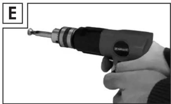
natural_image
Close-up of a hand holding a soldering iron, with no visible text or symbols on the tool or background.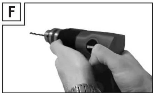
natural_image
Close-up of a hand using a drill bit to apply a tool, no visible text or symbolsIMPORTANT SAFETY INSTRUCTIONS 6
General 6
Work Area
Personal Safety
Tool Use and Care
Service
Air Source
Symbol Definitions
Specific Safety Instructions
Vibration Precautions
Functional Description
Specifications
Components and Controls
Initial Tool Set Up/Assembly
Air Supply
Operating Instructions
Tool Set Up
Drill Bit Removal
Drill Bit Installation
Workpiece and Work Area Set Up
General Operating Instructions
User-Maintenance Instructions
Cleaning, Maintenance, and
Lubrication 16
Troubleshooting 17
Parts List and Assembly 18
Diagram 18
Information about warranty and service processing 18
Lidl US LLC. warranty
Warranty terms
Scope of warranty
Processing of warranty claims
Environmental instructions and disposal information
Declaration of Conformity
Page
Page
Page 6
Page 6
Page 7
Page 8
Page 8
Page 8
Page 9
Page 9
Page 10
Page 10
Page 10
Page 10
Page 11
Page 14
Page 14
Page 14
Page 14
Page 14
Page 15
Page 15
Page
Page
Page
Page
Page
Page 18
Page 19
Page 19
Page 19
Page 20
Page 20
This is the safety alert symbol. It is used to alert you to potential personal injury hazards. Obey all safety messages that follow this symbol to avoid possible injury or death.
⚠️ DANGER Indicates a hazardous situation which, if not avoided, will result in death or serious injury.
⚠ WARNING Indicates a hazardous situation which, if not avoided, could result in death or serious injury.
⚠️ CAUTION Indicates a hazardous situation which, if not avoided, could result in minor or moderate injury.
NOTICE CAUTION Addresses practices not related to personal injury.
IMPORTANT SAFETY INSTRUCTIONS
INSTRUCTIONS PERTAINING TO A RISK OF FIRE, ELECTRIC SHOCK, OR INJURY TO PERSONS
⚠ WARNING When using tools, basic precautions should always be followed, including the following:
General
To reduce the risks of electric shock, fire, and injury to persons, read all the instructions before using the tool.
Work Area
- Keep the work area clean and well lighted. Cluttered benches and dark areas increase the risks of electric shock, fire, and injury to persons.
- Do not operate the tool in explosive atmospheres, such as in the presence of flammable liquids, gases, or dust. The tool is able to create sparks resulting in the ignition of the dust or fumes.
- Keep bystanders, children, and visitors away while operating the tool. Distractions are able to result in the loss of control of the tool.
Personal Safety
- Stay alert. Watch what you are doing and use common sense when operating the tool. Do not use the tool while tired or under the influence of drugs, alcohol, or medication. A moment of inattention while operating the tool increases the risk of injury to persons.
- Dress properly. Do not wear loose clothing or jewelry. Contain long hair. Keep hair, clothing, and gloves away from moving parts. Loose clothes, jewelry, or long hair increases the risk of injury to persons as a result of being caught in moving parts.
- Avoid unintentional starting. Be sure the switch is off before connecting to the air supply. Do not carry the tool with your finger on the switch or connect the tool to the air supply with the switch on.
IMPORTANT SAFETY INSTRUCTIONS
- Do not overreach. Keep proper footing and balance at all times. Proper footing and balance enables better control of the tool in unexpected situations.
Use safety equipment. A dust mask, non-skid safety shoes and a hard hat must be used for the applicable conditions.
Always wear eye protection. Wear ANSI-approved safety goggles.
Always wear hearing protection when using the tool. Prolonged exposure to high intensity noise is able to cause hearing loss. - Risk of Electric Shock. This tool is not provided with an insulated gripping surface. Contact with a "live" wire will also make exposed metal parts of the tool "live" and shock the operator.
- Avoid body contact with grounded surfaces such as pipes, radiators, ranges and refrigerators. There is an increased risk of electric shock if your body is grounded.
- Explore the workpiece to avoid contact with hidden wiring. Thoroughly investigate the workpiece for possible hidden wiring before performing work. Contact with live wiring will shock the operator.
Tool Use and Care
- Use clamps or another practical way to secure and support the workpiece to a stable platform. Holding the work by hand or
against the body is unstable and is able to lead to loss of control.
- Do not force the tool. Use the correct tool for the application. The correct tool will do the job better and safer at the rate for which the tool is designed.
- Do not use the tool if the switch does not turn the tool on or off. Any tool that cannot be controlled with the switch is dangerous and must be repaired.
- Disconnect the tool from the air source before making any adjustments, changing accessories, or storing the tool. Such preventive safety measures reduce the risk of starting the tool unintentionally. Turn off and detach the air supply, safely discharge any residual air pressure, and release the trigger before leaving the work area.
- Store the tool when it is idle out of reach of children and other untrained persons. A tool is dangerous in the hands of untrained users.
- Maintain the tool with care. Keep a cutting tool sharp and clean. A properly maintained tool, with sharp cutting edges reduces the risk of binding and is easier to control.
- Check for misalignment or binding of moving parts, breakage of parts, and any other condition that affects the tool's operation. If damaged, have the tool serviced before using. Many accidents are caused by poorly maintained tools. There is a risk of bursting if the tool is damaged.
- Use only accessories that are identified by the manufacturer for the specific tool model. Use of an accessory not intended for use with the specific tool model, increases the risk of injury to persons.
Service
■ Tool service must be performed only by qualified repair personnel.
- When servicing a tool, use only identical replacement parts. Use only authorized parts.
- Use only the lubricants supplied with the tool or specified by the manufacturer.
Air Source
Never connect to an air source that is capable of exceeding 200 psi. Over pressurizing the tool may cause bursting, abnormal operation, breakage of the tool or serious injury to persons. Use only clean, dry, regulated compressed air at the rated pressure or within the rated pressure range as marked on the tool. Always verify prior to using the tool that the air source has been adjusted to the rated air pressure or within the rated air-pressure range.
- Never use oxygen, carbon dioxide, combustible gases or any bottled gas as an air source for the tool. Such gases are capable of explosion and serious injury to persons.
Symbol Definitions
| Symbol | Property or Statement |
| n0 | No-load speed |
| .../min | Revolutions or reciprocation per minute |
| PSI | Pounds per square inch of pressure |
| ft-lb | Foot-pounds of torque |
| BPM | Blows per minute |
| CFM | Cubic Feet per Minute flow |
| SCFM | Cubic Feet per Minute flow at standard conditions |
| NPT | National pipe thread, tapered |
| NPS | National pipe thread, straight |
 | WARNING markingconcerning Risk of Eye Injury.Wear ANSI-approved eye protection. |
 | WARNING markingconcerning Risk of Hearing Loss.Wear hearing protection. |
 | WARNING markingconcerning Risk of Respiratory Injury. Wear NIOSH-approved dust mask/respirator. |
 | WARNING markingconcerning Risk of Explosion. |
Specific Safety Instructions
-
The warnings and precautions discussed in this manual cannot cover all possible conditions and situations that may occur. It must be understood by the operator that common sense and caution are factors which cannot be built into this product, but must be supplied by the operator.
WARNING Some dust created by power sanding, sawing, grinding, drilling, and other construction activities, contains chemicals known [to the State of California] to cause cancer, birth defects or other reproductive harm. Some examples of these chemicals are: -
Lead from lead-based paints
- Crystalline silica from bricks and cement or other masonry products
- Arsenic and chromium from chemically treated lumber
Your risk from these exposures varies, depending on how often you do this type of work. To reduce your exposure to these chemicals: work in a well ventilated area, and work with approved safety equipment, such as those dust masks that are specially designed to filter out microscopic particles. (California Health & Safety Code § 25249.5, et seq.)
WARNING The brass components of this product contain lead, a chemical known to the State of California to cause birth defects (or other reproductive harm). (California Health & Safety code § 25249.5, et seq.)
- Only use with accessories rated to handle the forces exerted by this tool during operation. Other accessories not designed for
PARKSIDE
the forces generated may break and forcefully launch pieces.
- Attach all accessories properly to the tool before connecting the air supply. A loose accessory may detach or break during operation.
- Obey the manual for the air compressor used to power this tool.
- Install an in-line shutoff valve to allow immediate control over the air supply in an emergency, even if a hose is ruptured.
- Use this tool with both hands only. Using tools with only one hand can result in loss of control.
- Do not lay the tool down until it has come to a complete stop. Moving parts can grab the surface and pull the tool out of your control.
Vibration Precautions
This tool vibrates during use. Repeated or long-term exposure to vibration may cause temporary or permanent physical injury, particularly to the hands, arms and shoulders. To reduce the risk of vibration-related injury:
Anyone using vibrating tools regularly or for an extended period should first be examined by a doctor and then have regular medical check-ups to ensure medical problems are not being caused or worsened from use. Pregnant women or people who have impaired blood circulation to the hand, past hand injuries, nervous system disorders, diabetes, or Raynaud's Disease
IMPORTANT SAFETY INSTRUCTIONS / INITIAL TOOL SET UP / ASSEMBLY
- should not use this tool. If you feel any symptoms related to vibration (such as tingling, numbness, and white or blue fingers), seek medical advice as soon as possible.
- Do not smoke during use. Nicotine reduces the blood supply to the hands and fingers, increasing the risk of vibration-related injury.
- Wear suitable gloves to reduce the vibration on effects on the user.
- Use tools with the lowest vibration when there is a choice.
Include vibration-free periods each day of work.
- Grip tool as lightly as possible (while still keeping safe control of it). Let the tool do the work.
- To reduce vibration, maintain tool as explained in this manual. If abnormal vibration occurs, stop immediately.
Functional Description
Specifications
| Maximum Air Pressure | 6,8 bar |
| Maximum Speed | 2200 min ^1 |
| Admission | 1-10 mm |
| Suitable for | Wood and metal drills, as well as commercially available bits |
| Air supply | Maintenance unit with filter pressure reducer and oil mist |
| Required air quality | Cleaned, condensate free and oil mist |
| Compressors | With min. 50 l boiler volume |
The noise and vibration values were determined according to EN ISO 15744 and EN ISO 28927-2.
SPL L_pA : 80 dB(A)
L_WA : 3 db (A)
Uncertainty: 3 dB
Vibration: 360 m/s ^4
Uncertainty: 3 m/s^2
Components and Controls
natural_image
Black industrial electric drill bit with trigger, isolated on white background (no text or symbols visible)Initial Tool Set Up/Assembly
Read the ENTIRE IMPORTANT SAFETY INFORMATION section at the beginning of this manual including all text under subheadings therein before set up or use of this product.
NOTICE For additional information regarding the parts listed in the following pages, refer to the Assembly Diagram near the end of this manual.
NOTICE This air tool may be shipped with a protective plug covering the air inlet. Remove this plug before set up.
Air Supply
WARNING TO PREVENT SERIOUS INJURY FROM EXPLOSION:
Use only clean, dry, regulated, compressed air to power this tool. Do not use oxygen, carbon dioxide, combustible gases, or any other bottled gas as a power source for this tool.
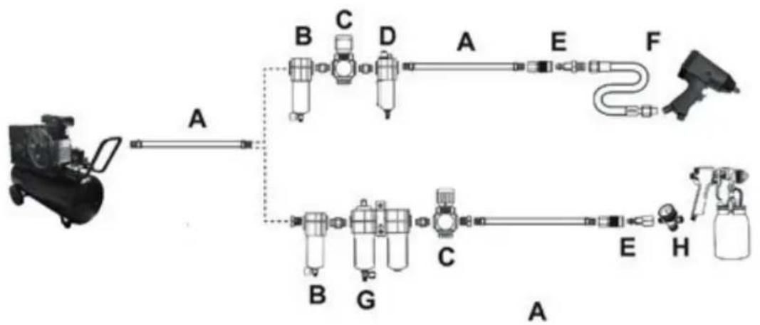
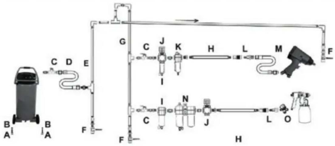
Incorporate a filter, regulator with pressure gauge, oiler, in-line shutoff valve, and quick coupler for best service, as shown on Figure A on page 8 and Figure B on page 9. An in-line shutoff ball valve is an important safety device because it controls the air supply even if the air hose is ruptured. The shutoff valve should be a ball valve because it can be closed quickly.
NOTICE If an automatic oiler system is not used, add a few drops of Pneumatic Tool Oil to the airline connection before operation. Add a few more drops after each hour of continual use.
- Attach an air hose to the compressor's air outlet. Connect the air hose to the air inlet of the tool. Other components, such as a coupler plug and quick coupler, will make operation more efficient, but are not required.
A WARNING TO PREVENT SERIOUS INJURY FROM ACCIDENTAL OPERATION:
Do not install a female quick coupler on the tool. Such a coupler contains an air valve that will allow the air tool to retain pressure and operate accidentally after the air supply is disconnected.
/// PARKSIDE
NOTICE Air flow, and therefore tool performance, can be hindered by undersized air supply components. The air hose must be long enough to reach the work area
with enough extra length to allow free movement while working.
- Release the tool's trigger.
- Close the in-line shutoff valve between the compressor and the tool.
Turn on the air compressor according to the manufacturer's directions and allow it to build up pressure until it cycles off. - Adjust the air compressor's output regulator so that the air output is enough to properly power the tool, but the output will not exceed the tool's maximum air pressure at any time. Adjust the pressure gradually, while checking the air output gauge to set the right pressure range.
- Inspect the air connections for leaks. Repair any leaks found.
- If the tool will not be used at this time, turn off and detach the air supply, safely discharge any residual air pressure, and release the trigger to prevent accidental operation.
NOTICE Residual air pressure should not be present after the tool is disconnected from the air supply. However, it is a good safety measure to attempt to discharge the tool in a safe fashion after disconnecting to ensure that the tool is disconnected and not powered.
flowchart
graph LR
    A["Steamer"] -->|A| B["Gasifier"]
    B --> C["Component A: B, C, D"]
    C --> D["Component B: B, G"]
    D --> E["Component C: C, E"]
    E --> F["Component F: Gasifier"]
    F --> H["Product"]
    style A fill:#f9f,stroke:#333
    style B fill:#ccf,stroke:#333
    style C fill:#cfc,stroke:#333
    style D fill:#fcc,stroke:#333
    style E fill:#cff,stroke:#333
    style F fill:#ffc,stroke:#333
    style G fill:#cfc,stroke:#333
    style H fill:#fcc,stroke:#333
| Description | Function | |
| A | Air Hose | Connects air to tool |
| B | Filter | Prevents dirt and condensation from damaging tool or workpiece |
| C | Regulator | Adjusts air pressure to tool |
| D | Lubricator (optional) | For air tool lubrication |
| E | Coupler and Plug | Provides quick connection and release |
| F | Leader Hose (optional) | Increases coupler life |
| G | Air Cleaner / Dryer (optional) | Prevents water vapor from damaging workpiece |
| H | Air Adjusting Valve (optional) | For fine tuning airflow at tool |
flowchart
graph LR
    A["Tramper with B and A units"] --> B["Cylinder"]
    B --> C["Ductor"]
    C --> D["Emitter"]
    D --> E["Fueler"]
    E --> F["Gauge"]
    F --> G["Jump"]
    G --> H["Kump"]
    H --> I["Hump"]
    I --> J["Lump"]
    J --> K["Mirror"]
    K --> L["Finder"]
    L --> M["Box"]
    M --> N["Box"]
    N --> O["Box"]
    O --> P["Box"]
    P --> Q["Box"]
    Q --> R["Box"]
    R --> S["Box"]
    S --> T["Box"]
    T --> U["Box"]
    U --> V["Box"]
    V --> W["Box"]
    W --> X["Box"]
    X --> Y["Box"]
| Description Function | ||
| A Vibration Pads For noise and vibration reduction | ||
| B Anchor Bolts Secures air compressor in place | ||
| C Ball Valve Isolates sections of system for maintenance | ||
| D Isolation Hose For vibration reduction | ||
| E Main Air Line - 3/4" minimum recommended | Distributes air to branch lines | |
| F Ball Valve To drain moisture from system | ||
| G Branch Air Line -1/2" minimum recommended | Brings air to point of use | |
| H Air Hose Connects air to tool | ||
| I Filter Prevents dirt and condensation from damaging tool or workpiece | ||
| J Regulator Adjusts air pressure to tool | ||
| K | Lubricator (optional) | For air tool lubrication |
| L | Coupler and Plug | Provides quick connection and release |
| M | Leader Hose (optional) | Increases coupler life |
| N Air Cleaner / Dryer (optional) | Prevents water vapor from damaging workpiece | |
| O | Air Adjusting Valve (optional) | For fine tuning airflow at tool |
Operating Instructions
Read the ENTIRE IMPORTANT SAFETY INFORMATION section at the beginning of this manual including all text under subheadings therein before set up or use of this product. Inspect tool before use, looking for damaged, loose, and missing parts. If any problems are found, do not use tool until repaired.
Tool Set Up
A WARNING TO PREVENT SERIOUS INJURY FROM ACCIDENTAL OPERATION: Turn off the tool, detach the air supply, safely discharge any residual air pressure in the tool, and release the trigger before performing any inspection, maintenance, or cleaning procedures.
TO PREVENT SERIOUS INJURY: Do not adjust or tamper with any control or component in a way not specifically explained within this manual. Improper adjustment can result in tool failure or other serious hazards.
Drill Bit Installation
ACAUTION Wear heavy-duty work gloves to provide protection when inserting and removing drill bits. Drill bits become very hot during use.
Do not remove drill bits until the bit has cooled.
- Loosen the Chuck with the Chuck Key until the jaws of the drill are opened enough to fit the drill bit.
- Place the desired drill bit into the drill between the Chuck Jaws.
NOTICE In addition to single or double-ended screwdriver bits, adapters with hexagonal shafts with matching socket heads can also be used.
- Hand tighten the Chuck until the bit is held securely in place, contered between the Chuck Jaws.
- Insert the tip of the Cuck Key into a hole on the side of the Chuck so that the teeth on the Key to tighten the Chuck securely and remove the Key.
NOTICE Use sharp bits. Dull, bent, damaged bits will cause stress on the drill and/or break.
Workpiece and Work Area Set Up
- Designate a work area that is clean and well-lit. The work area must not allow access by children or pets to prevent distraction and injury.
- Route the air hose along a safe route to reach the work area without creating a tripping hazard or exposing the air hose to possible damage. The air hose must be long enough to reach the work area with enough extra length to allow free movement while working.
OPERATING INSTRUCTIONS / USER-MAINTENANCE INSTRUCTIONS
- Secure loose workpieces using a vise or clamps (not included) to prevent movement while working.
- There must not be hazardous objects (such as utility lines or foreign objects) nearby that will present a hazard while working.
General Operating Instructions
If an automatic oiler is not used, add a few drops of Pneumatic Tool Oil to the airline connection before use. Add a few drops more after each hour of continual use.
- With the proper chisel attached to the Air Hammer, attach the air supply to the Air Inlet at the base on the Housing.
■ Turn on the air supply.
- Press the chisel against the work surface and squeeze the Trigger to start the tool. Do not force the Air Hammer against the work surface. Easy, light pressure works best.
If the tool requires more force to accomplish the task, verify that the tool receives sufficient, unobstructed airflow (CFM) and increase the pressure (PSI) output of the regulator up to the maximum air pressure rating of this tool.
NOTICE TO PREVENT INJURY FROM TOOL OR ACCESSORY FAILURE: Do not exceed the tool's maximum air pressure rating. If the tool still does not have sufficient force at maximum pressure and sufficient airflow, then a larger tool may be required.
PARKSIDE
- To prevent accidents, turn off the tool, detach the air supply safely discharge any residual air pressure in the tool, and release the trigger after use. Clean external surfaces of the tool with clean, dry cloth, and apply a thin coat of tool oil. Then store the tool indoors out of children's reach.
User-Maintenance Instructions
Procedures not specifically explained in this manual must be performed only by a qualified technician.
WARNING TO PREVENT SERIOUS INJURY FROM ACCIDENTAL OPERATION: Turn off the tool, detach the air supply, safely discharge any residual air pressure in the tool, and release the trigger before performing any inspection, maintenance, or cleaning procedures. TO PREVENT SERIOUS INJURY FROM TOOL FAILURE: Do not use damaged equipment. If abnormal noise, vibration, or leaking air occurs, have the problem corrected before further use.
TO PREVENT SEROUS INJURY FROM EXPLOSION: Lubricate the tool only with specified lubricants. Lubricate the air inlet using only pneumatic tool oil. Other lubricants may damage the mechanism and may be highly flammable, causing an explosion.
Cleaning, Maintenance, and Lubrication
NOTICE These procedures are in addition to the regular checks and maintenance explained as part of the regular operation of the air-operated tool.
BEFORE EACH USE, inspect the general condition of the tool. Check for:
- loose hardware or housing,
- misalignment or binding of moving parts,
■ dull, chipped, or cracked chisels, - cracked or broken parts, and
- any other condition that may affect its safe operation.
Daily - Air Supply Maintenance: Every day, maintain the air supply according to the component manufacturers' instructions. Maintain the lubricator's oil level. Drain the moisture filter regularly. Performing routine air supply maintenance will allow the tool to operate more safely and will also reduce wear on the tool.
- Quarterly (every 3 months) – Tool Disassembly, Cleaning, and Inspection: Have the internal mechanism cleaned, inspected, and lubricated by a qualified technician.
Troubleshooting
| Problem Possible | Causes Likely Solutions | |
| Decreased output. | Not enough air pressure and/ or air flow.Obstructed trigger.Incorrect lubrication or not enough lubrication.Blocked air inlet screen (if equipped).Air leaking from loose housing.Mechanism contaminated.Vane wear or damage. | Check for loose connections and make sure that air supply is providing enough air flow (CFM) at required pressure (PSI) to the tool's air inlet. Do not exceed maximum air pressure.Clean around trigger to ensure free movement.Lubricate using air tool oil according to directions.Clean air inlet screen of buildup.Make sure housing is properly assembled and tight.Have qualified technician clean and lubricate mechanism.Install in-line filter in air supply as stated in Setup: Air Supply.Replace all vanes as set. |
| Severe air leakage.(Slight air leakage is normal, especially on older tools.) | Cross-threaded housing components.Loose housing.Damaged valve or housing.Dirty, worn or damaged valve. | Check for incorrect alignment and uneven gaps. If cross-threaded, disassemble and replace damaged parts before use.Tighten housing assembly.If housing cannot tighten properly, internal parts may be misaligned. Technician needs to disassemble tool, align parts and reassemble.Replace damaged components.Clean or replace valve assembly. |
| Housing heats during use. | Incorrect lubrication or not enough lubrication.Worn parts. | Lubricate using air tool oil according to directions.Have qualified technician inspect internal mechanism and replace parts as needed. |
| Follow all safety precautions whenever diagnosing or servicing the tool. Disconnect air supply before service. | ||
NOTICE If product has no serial number, record month and year of purchase instead.
NOTICE Some parts are listed and shown for illustration purposes only, and are not available individually as replacement parts.
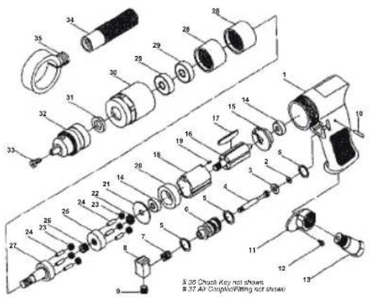
Parts List and Assembly Diagram
| Part | Description | Qty |
| 1 | Housing | 1 |
| 2 | O-Ring | 1 |
| 3 | O-Ring | 1 |
| 4 | Valve Stem | 1 |
| 5 | O-Ring | 3 |
| 6 | Bushing | 1 |
| 7 | Trigger Spring | 1 |
| 8 | Trigger | 1 |
| 9 | Trigger Screw | 1 |
| 10 | Pin | 1 |
| 11 | Muffler Cover | 1 |
| 12 | Screw | 2 |
| 13 | Air Inlet | 1 |
| 14 | Bearing | 2 |
| 15 | End Plate | 1 |
| 16 | Rotor | 1 |
| 17 | Rotor Blade | 5 |
| 18 | Cylinder | 1 |
| 19 | Pin | 1 |
| 20 | Front Plate | 1 |
| 21 | Washer | 1 |
| 22 | Gear | 1 |
| 23 | Gear | 6 |
| 24 | Pin | 6 |
| 25 | Gear Plate | 1 |
| 26 | Gear | 1 |
| 27 | Work Spindle | 1 |
| 28 | Thread Ring Gear | 2 |
| 29 | Bearing | 2 |
| 30 | Clamp Nut | 1 |
| 31 | Washer | 1 |
| 32 | Chuck | 1 |
| 33 | Chuck Screw | 1 |
| 34 | Handle | 1 |
| 35 | Handle Ring | 1 |
| 36 | Chuck Key | 1 |
| 37 | Air Coupler/ Fitting | 1 |
Information about warranty and service processing
Lidl US LLC. warranty
Dear customer, the warranty for this device is 3 years from the date of purchase. In the event of product defects you have legal rights against the retailer of this product. Your legal rights are not limited in any way by our warranty detailed below.
PARKSIDE
Warranty terms
The warranty period begins on the date of purchase. Please keep the original sales receipt in a safe location. This document is required as your proof of purchase.
Should this device show any fault in materials or manufacture within three years from the date of purchase, we will repair or replace it - at our choice - free of charge to you. Warranty services require the defective device and the proof of purchase (sales receipt) to be presented within the three-year period along with a brief written description of the defect and when it occurred.
If the defect is covered by our warranty, we will return the repaired device or replacement thereof. A repair or exchange of the device does not extend a new warranty period.
Scope of warranty
The device has been manufactured to strict quality guidelines and meticulously examined before delivery. The warranty applies to faults in material or manufacture. This warranty does not apply to product parts subject to normal wear and tear and which can therefore be considered as wear items, or to damage to fragile parts, e.g. switches, storage batteries or glass parts.
This warranty becomes void if the device has been damaged or improperly used or maintained. All instructions provided in the operating instructions must be followed strictly to constitute proper use of the product. Applications and actions which the operating instructions warn of or advise against must be avoided without fail.
This product is intended for private, non-commercial use only. The warranty is void in the case of inappropriate and improper handling, use of force and of any intervention which was not carried out by our authorized service branch.
Processing of warranty claims
Please follow the instructions below to ensure quick processing of your matter: When inquiring about your product please have your receipt and product number (e.g. IAN) ready

as your proof of purchase. The item number can be found on the type plate, engraving, the cover page of your instructions (bottom left) or the decal at the back or bottom. In the event of malfunctions or other defects please first contact the service department below by phone or e-mail.
A product recorded as defective, along with the proof of purchase (sales receipt) and a description of the defect and when it occurred, can then be returned free of charge to you to the service address provided.
Note:
Visit www.lidl-service.com to download this and many other manuals, product videos and software.
How to contact us:
USA
Name: Customer Service
Website: www.lidl.com/contact-us
Phone: 1-844-543-5872
Registered office: United States of America
Please note the following address is not a service address. Please first contact the above service address.
Address:
Lidl US LLC.
Arlington, VA 22202
United States of America
IAN 285212
Environmental instructions and disposal information

Don't waste, recycle!
Equipment, accessories and packaging should be recycled in an environmentally friendly manner.
Do not dispose of the compressed air tool through your household waste, or throw into fire or water. If possible, non-operational devices should be recycled. Contact your local retailer for information.
Declaration of Conformity
We,
Lidl US LLC.,
Arlington, VA 22202
declare on our sole responsibility the product
PNEUMATIC DRILL DRIVER
Item number: 2054
Year of manufacture: 2017 / 34
IAN: 285212
Model: PARKSIDE PNEUMATIC
DRILL DRIVER PDBS 2200 A2
to meet the basic safety requirements of European Directives
Machinery Directive
EC Directive 2006 / 42 / EC
and its amendments.
The conformity assessment is based on the following harmonised standards:
EN ISO 11148-3:2013
natural_image
Black industrial electric drill with a metal drill bit, no visible text or symbolsUnited States of America
Last Information Update.

- PNEUMATIC DRILL DRIVER PDBS 2200 A2 TALADRADORA NEUMÁTICA PDBS 2200 A2
- ES
- IMPORTANT SAFETY INSTRUCTIONS 6
- Functional Description
- Initial Tool Set Up/Assembly
- Operating Instructions
- User-Maintenance Instructions
- Cleaning, Maintenance, and
- Environmental instructions and disposal information
- Declaration of Conformity
- Page
- Page 10
- Page 14
- Page 15
- Page 20
- IMPORTANT SAFETY INSTRUCTIONS
- INSTRUCTIONS PERTAINING TO A RISK OF FIRE, ELECTRIC SHOCK, OR INJURY TO PERSONS
- General
- Work Area
- Personal Safety
- Tool Use and Care
- Service
- Air Source
- Specific Safety Instructions
- Vibration Precautions
- IMPORTANT SAFETY INSTRUCTIONS / INITIAL TOOL SET UP / ASSEMBLY
- Components and Controls
- Air Supply
- Tool Set Up
- Drill Bit Installation
- Workpiece and Work Area Set Up
- OPERATING INSTRUCTIONS / USER-MAINTENANCE INSTRUCTIONS
- General Operating Instructions
- Cleaning, Maintenance, and Lubrication
- Information about warranty and service processing
- Lidl US LLC. warranty
- Warranty terms
- Scope of warranty
- Processing of warranty claims
- Note:
- How to contact us:
- USA
- Address:
- Lidl US LLC.
- Don't waste, recycle!
- PNEUMATIC DRILL DRIVER
- DRILL DRIVER PDBS 2200 A2
- Machinery Directive
Brand : PARKSIDE
Model : PDKS 6.3 A1
Category : Saw