
HCM 25 - Machine tool SCHEPPACH - Free user manual and instructions
Find the device manual for free HCM 25 SCHEPPACH in PDF.

User questions about HCM 25 SCHEPPACH
0 question about this device. Answer the ones you know or ask your own.
Ask a new question about this device
Download the instructions for your Machine tool in PDF format for free! Find your manual HCM 25 - SCHEPPACH and take your electronic device back in hand. On this page are published all the documents necessary for the use of your device. HCM 25 by SCHEPPACH.
USER MANUAL HCM 25 SCHEPPACH
hcm 25
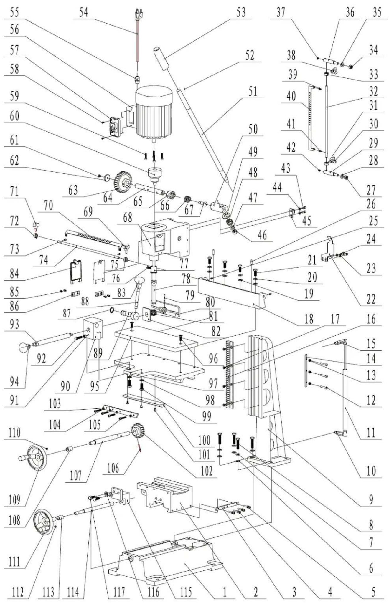
natural_image
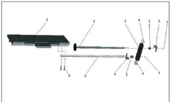
Industrial milling machine with dual levers and a vertical shaft (no visible text or symbols)D 03 - 08
GB 09-13
FR 14-18
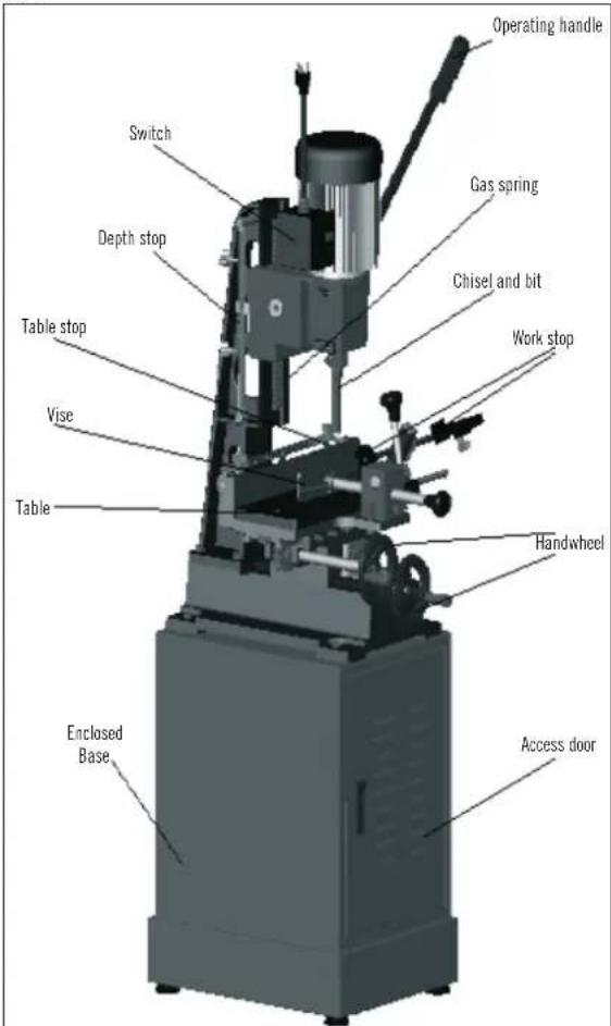
HCM 25 Mortiser
Garantie
Apparent defects must be notified within 8 days from the receipt of the goods. Otherwise, the buyer's rights of claim due to such defects are invalidated. We guarantee for our machines in case of proper treatment for the time of the statutory warranty period from delivery in such a way that we replace any machine part free of charge which provably becomes unusable due to faulty material or defects of fabrication within such period of time. With respect to parts not manufactured by us we only warrant insofar as we are entitled to warranty claims against the upstream suppliers. The costs for the installation of the new parts shall be borne by the buyer. The cancellation of sale or the reduction of purchase price as well as any other claims for damages shall be excluded.
Garantie
Günzburger Straße 69
D-89335 Ichenhausen
Verehrter Kunde,
Fig. 11
Fig. 12
Manufacturer
scheppach
Günzburger Straße 69
D-89335 Ichenhausen
Dear customer,
We wish you much pleasure and success with your new scheppach machine.
Note
In accordance with valid product liability laws, the manufacturer of this device shall not be responsible for damage to and from this device which results from:
nal schrts.
ance with the legal and applicable electrical directives
We recommend
that you read through the entire operating instructions before putting into operation.
These operating instructions are to assist you in getting to know your machine and utilize its proper applications.
The operating instructions contain important notes on how you work with the machine safely, expertly, and economically, and how you can avoid hazards, save repair costs, reduce downtime and increase the reliability and service life of the machine.
operating instructions, you must be careful to observe your country's applicable regulations.
The operating instructions must always be near the machine. Put them in a plastic folder to protect them from dirt and humidity. They must be read by every operator before beginning work and observed conscientiously. Only persons who have been trained in the use of the machine and have been informed of the various dangers may work
served.
operating instructions and your country's applicable regulations, you should observe the generally recognized technical rules concerning the operation of woodworking machines.
General notes
age. Inform the supplier immediately of any faults.
the machine by carefully reading these instructions.
placement parts. You can find replacement parts at your scheppach dealer.
and year of construction of the machine.
hcm 25
| Supply extent | |
| Carton box base (optional equipment) | |
| Accessory pack | |
| Carton box mortiser | Morticing machine with motor |
| Operating handle | |
| 2 Hand wheel handles | |
| Chuck key | |
| Chisel | |
| Wooden table | |
| Technical data | |
| Dimensions W/D/H mm | |
| Table size W/L mm | |
| Table height mm | |
| Table adjustment W/D mm | |
| Drill stroke mm | 220 |
| Distance drill – fence mm | |
| Drill depth max. mm | |
| Drill size max. mm | 25 |
| Workpiece height max. mm | 200 |
| Table movement mm | |
| Spindle speed 1/min | |
| Chisel capacity mm | 6.35 – 25,. |
| Chisel shank/Bushing size mm | 19.05 |
| Maximum chisel stroke mm | 220 |
| Distance fence – centre chisel mm | |
| Chuck capacity mm | 16 |
| Weight kg | 91 |
| Drive | |
| Motor | |
| Consumption power P1 W | |
| Spindle speed | |
| Plug | Schuko |
Subject to technical modifications!
In these operating instructions we have marked the places that have to do with your safety with this sign.
⚠️ Safety notes
who work on the machine.
condition in accordance with its designated use and the instructions set out in the operating manual, and only by safety-conscious persons who are fully aware of the risks involved in operating the machine. Any functional disorders, especially those affecting the safety of the machine, should therefore be rectified immediately.
the machine.
to the machine are always complete and perfectly leg- ible.
hands from the rotating cutting tool.
ground.
lines.
nected to the power supply.
Trainees must be at least 16 years of age, but may only operate the machine under adult supervision.
from their work.
tension if a second person is working at the circular saw-bench removing cut workpieces. The second person may not stand anywhere else but at the take-off table end.
and wood scrap.
and other jewelry.
- see Electrical Connection.
moved or rendered unusable.
chine may only be carried out when the motor is switched off. Pull the power supply plug and wait for the rotating tool to completely stop.
rectifying any malfunctions.
and covers must be mounted.
rectifying any malfunctions.
the power supply plug.
even if only minor changes of place are envisaged. Properly reconnect the machine to the supply mains before recommissioning.
completing repair and maintenance procedures.
⚠️ Use only as authorized
The machine corresponds to the valid EC guideline.
front and at the rear using both hands and lift the machine.
placed firmly upon a stable stand resembling a table. The working height should be 850 mm.
chine must be clear of interfering foreign matter to prevent accidents occurring.
i.e. nails or screws.
machining of wood and materials similar to wood. Only original scheppach tools and accessories may be used. Please observe the „Special Tool Accessories“.
condition in accordance with its designated use and the instructions set out in the operating manual, and only by safety-conscious persons who are fully aware of the risks involved in operating the machine. Any functional disorders, especially those affecting the safety of the machine, should therefore be rectified immediately.
generally recognized safety-technical rules must also be adhered to.
and operated by persons familiar with it and instructed in its operation and procedures. Arbitrary alterations to the machine release the manufacturer from all responsibility for any resulting damages.
nal accessories and original tools made by the manufacturer.
is not responsible for any damages resulting from unauthorized use; risk is the sole responsibility of the opera-
⚠️ Remaining hazards
The machine has been built using modern technology in accordance with recognized safety rules. Some remaining hazards, however, may still exist.
hands if it is incorrectly fed.
is not properly secured or fed, such as working without a limit stop.
to injuries caused by electricity.
accessories must be observed and carefully read when scheppach special accessories are used.
maining hazards which are not yet evident may still be present.
instructions in „Safety Precautions“, „Proper Use“ and in the entire operating manual.
Fig. 1
Assembly and Installation
All assembly and retrofitting work may only be performed when the mains plug has been disconnected.
The mortiser should be secured to the stand with four M12 x 120 hexagon screws (provided), using the holes in the base. Make sure there is enough room on each side of the mortiser for the size stock you plan to use.
Putting into Operation
Please observe the safety instructions!
The machine may only be put into operation when all of the protective and saftey devices have been mounted. Installing chisel and bit
Fig. 2
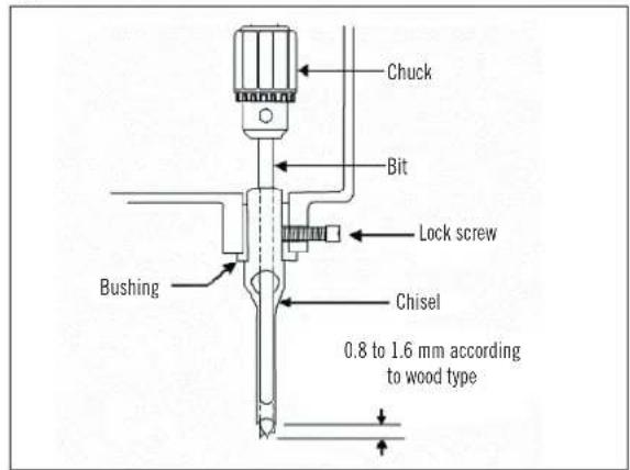
the head. Tighten the screw just enough to hold the chisel in place.
Attention: The slot in the side of the chisel must show to the left or to the right, never to the front or to the back. This will allow the ejection of chips when making mortises.
the chuck and lock it with the chuck key.
the chisel points, dictated by the type of wood.
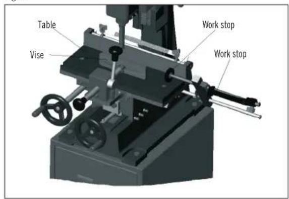
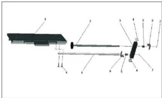
Work piece stop, Fig. 3
The work piece stop is mounted to the table.
After the correct setting, it is fastened by means of the clamping handles.
Fig. 3
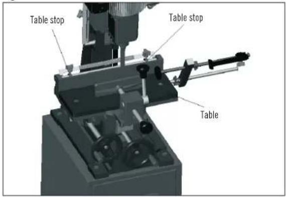
Operating instructions
vice. With the right hand wheel, move the table forward and backward, with the left hand wheel move the table to the left and to the right.
Fig. 5
ily into the work piece by pulling the operating handle down. Attention: The speed of pulling the handle down must be efficient but smooth, in order to avoid burning at the bit. Yet if the chisel and bit are pulled down too
ent rates of feed for different woods must be learned through experience.
the left hand wheel for each successive cut. The direction of movement must allow the chips to clear freely. Move the work piece so that the slot in the chisel is releasing the chips into the already cut part of the work piece – see Fig. 6.
Fig. 6
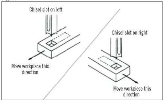
overheating and a possible breakage of chisel and bit. When cutting deep mortises, make the cut in several stages of approx. 25 mm depth each, to allow chips to clear. To prevent breakout at the back of the work piece when cutting through mortises, use a piece of scrap material under the work piece as support.
Electrical Connection
The electric motor is connected in a ready-to-operate state.
regulations.
The mains connection at the customer's work place and the extension cable used must correspond to these regulations.
Important information
The motor automatically switches off if it is overloaded. The motor can be switched on again after a cooling-down period (varies timewise).
Faulty electrical connecting leads
Insulation damage often occurs at electrical connecting leads.
Causes include:
through windows or the cracks of doors.
the connecting leads.
connecting lead from the wall socket.
Faulty electrical connecting leads such as these may not be used and are highly dangerous due to the insulation damage.
Check electrical connecting leads regularly for damage. Ensure that the connecting lead is not attached to the mains supply when you are checking it.
Electrical connecting leads must correspond to the relevant
on the connecting lead by regulation.
Single-phase motor
section of 1.5 mm ^2 . Extension leads whose length is over 25 m must have a cross-section of at least 2.5 mm ^2 .
fuse.
Connections or repairs on the electrical equipment may only be carried out by an electrician.
Please give the following information if you have any en-
If your are sending back the motor, always send the complete drive unit with the switch.
Maintenance
as cleaning and lubrication and routine adjustment and sharpening of the chisel and bit.
Dust the machine down after each use and, as necessary, use light applications of oil or grease to lubricate linkages, moving parts, etc.
Sharpening chisel and bit
The chisel and bit should be kept sharp for best perform-
lead to overheating and breakage to chisel or bit. If chisel and bit are badly worn and become difficult to sharpen, they should be replaced.
the original shape of the bit. File the inside edge of the spur, the sides of the brad point, and the cutting edge
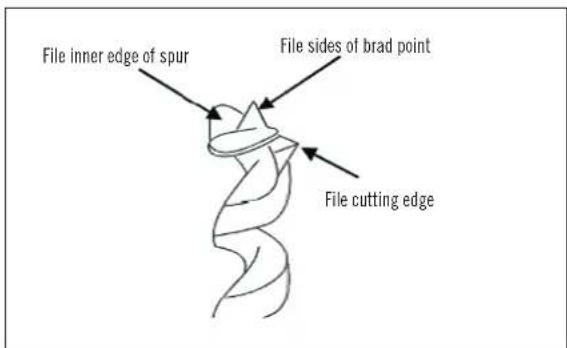
Do not file the outside edge of the spur as this will affect the diameter of the bit.
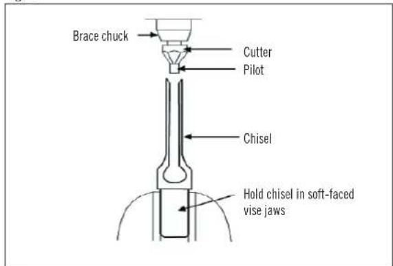
correct size pilot. (Pilot size will differ depending on the size of your chisel.) Depending on the degree of wear, two or three turns of the cutter should be enough to sharpen the chisel, as shown in Fig. 8.
Fig. 8
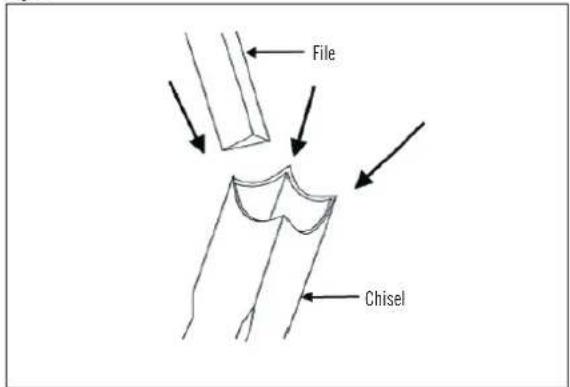
the outside of the chisel with a fine oilstone.
Fig. 9
Special Accessories
Article Article No.
Chisels
with drill 6 mm 8995 1100
with drill 8 mm 8995 1200
with drill 10 mm 8995 1300
with drill 12 mm 8995 1400
with drill 16 mm 8995 1600
Sharpening drill
6-12 mm 8995 1500
16 mm 8995 1700
Fig. 10
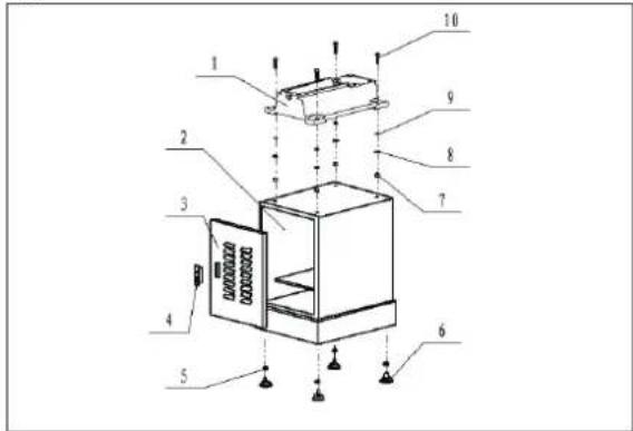
Fig. 11
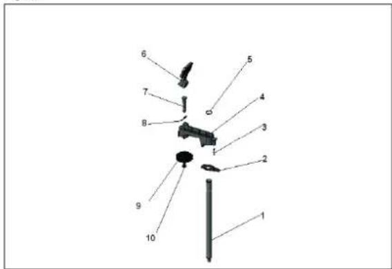
Fig. 12
Manufacteur:
scheppach
Fig. 11
Fig. 12
EC Declaration of Conformity
We, scheppach Fabrikation von Holzbearbeitungsmaschinen GmbH, Günzburger Str. 69, D-89335 Ichenhausen hereby declare that the machine named below corresponds to
design and construction and in the version which we introduced to the market. This declaration becomes invalid if changes are made to the machine without our consent.
Machine description: Morticer
Machine model: hcm 25
EC machine directive 98/37/EG (<28.12.2009), EC machine directive 2006/42/EG (>29.12.2009), EC Low voltage directive 2006/95/EWG, EC-EMV directive 2004/108/EWG.
Applied harmonized European Standards:
EN 847-1, EN 13849-1, EN 1870-1
TÜV Rheinland Product Safety 51101 Köln
Engaged for EC design examination (EC design certification no. AM 50033804)
on behalf of Wolfgang Windrich (Technical manager)