
FBH6TS - Log splitter SCHEPPACH - Free user manual and instructions
Find the device manual for free FBH6TS SCHEPPACH in PDF.

User questions about FBH6TS SCHEPPACH
0 question about this device. Answer the ones you know or ask your own.
Ask a new question about this device
Download the instructions for your Log splitter in PDF format for free! Find your manual FBH6TS - SCHEPPACH and take your electronic device back in hand. On this page are published all the documents necessary for the use of your device. FBH6TS by SCHEPPACH.
USER MANUAL FBH6TS SCHEPPACH
natural_image
Technical line drawing of a mechanical device with wheels and a grid-patterned frame (no text or symbols)
HL570LS
FBH6TS
| DE | HolzspalterOriginalbetriebsanleitung | 9 |
| GB | Log splitterTranslation of original instruction manual | 27 |
| FR | Fendeur de bûchesTraduction des instructions d'origine | 42 |
| NO | VedkapperOversettelse av den originale brukerveiledningen | 59 |
natural_image
Technical line drawing of a mechanical assembly with rollers and fasteners (no text or symbols)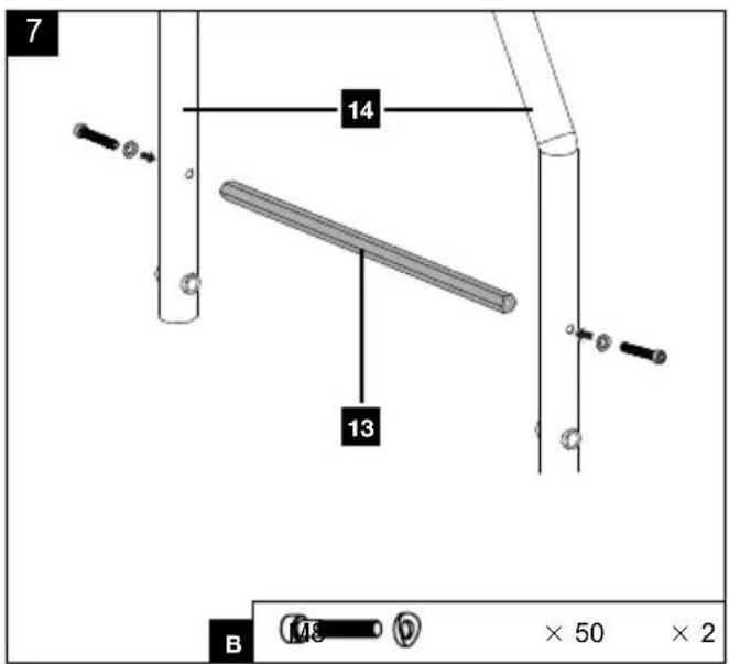
natural_image
Diagram of a machine with a hammer and sprocket crossed out, no text or symbols present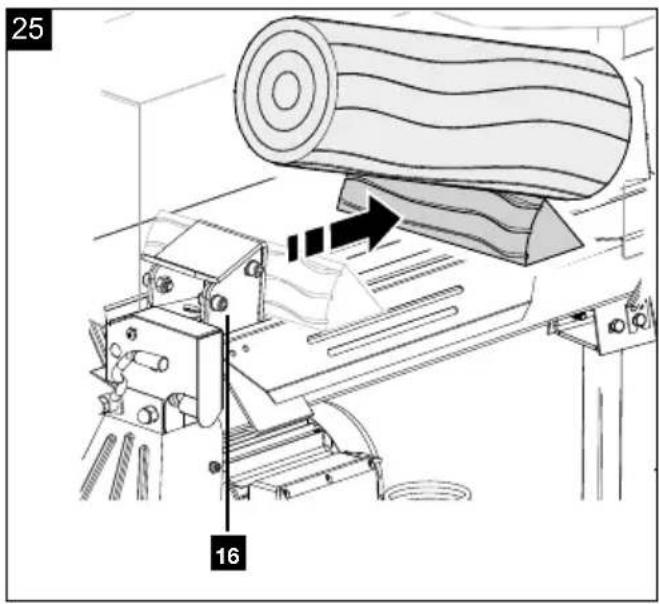
natural_image
Technical line drawing of a mechanical machine with rollers and a conveyor belt, showing motion direction (no text or symbols)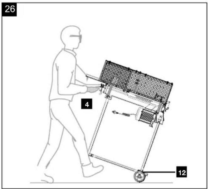
Günzburger Straße 69
D-89335 Ichenhausen
Verehrter Kunde,
Homepage: https://www.scheppach.com/de/service
Explanation of the symbols on the product
Symbols are used in this manual to draw your attention to potential hazards. The safety symbols and the accompanying explanations must be fully understood. The warnings themselves will not rectify a hazard and cannot replace proper accident prevention measures.
 | Warning - Read the operating manual to reduce the risk of injury. |
 | Wear hearing protection. Exposure to noise can cause hearing loss. |
 | Wear safety shoes. |
 | Use work gloves. |
 | Wear safety goggles. Sparks created during work or fragments, chippings and dust ejected by the product can cause sight loss. |
 | Anchorage point for crane hook |
 | Anchorage point for tension straps |
 | Risk of burns from hot surfaces! Do not touch! |
 | Removing or modifying protective or safety equipment is prohibited. |
 | Do not let hydraulic oil run onto the floor.Dispose of waste oil properly at the on-site waste oil collection point. Dumping used oil in the soil or mixing it with waste is prohibited. |
 | Attention! Before starting repair, maintenance and cleaning work, switch off the engine and unplug the mains plug. |
 | Warning against electrical voltage. |
 | Attention! Mains voltage! |
 | Do not reach into the splitting area!Danger of injury! Danger of cutting and crushing! |
 | Do not reach into the machine unprotected! |
 | Attention! Moving parts! |
 | Only the operator may stand in the working area of the machine. Keep uninvolved persons as well as pets and livestock away from the danger zone (minimum distance 5 m). |
 | Adjusting the stroke limitation |
 | Operate the product firmly with both hands! |
 | Maximum trunk length |
 | Maximum trunk diameter |
 | The product complies with the applicable European directives. |
Table of contents: Page:
- Introduction....30
- Product description (Fig. 1) 30
- Scope of delivery 30
- Proper use 31
- General safety instructions.... 31
- Additional safety instructions.... 32
- Residual risks 32
- Technical data.... 32
- Unpacking 33
- Assembly 33
- Start-up 35
- Working instructions 36
- Transport (Fig. 26) 37
- Maintenance 37
- Electrical connection 38
- Cleaning 39
- Storage 39
- Repair & ordering spare parts 40
- Disposal and recycling....40
- Troubleshooting 41
- Declaration of conformity 75
1. Introduction
Manufacturer:
Scheppach GmbH
Günzburger Straße 69
D-89335 Ichenhausen
Dear Customer,
We hope your new product brings you much enjoyment and success.
Note:
In accordance with the applicable product liability laws, the manufacturer of this product assumes no liability for damage to the product or caused by the product arising from:
- Improper handling
• Non-compliance with the operating manual
• Repairs carried out by third parties, unauthorised specialists
• Installing and replacing non-original spare parts - Improper use
- Failure of the electrical system in the event of the electrical regulations and VDE provisions 0100, DIN 57113 / VDE 0113 not being observed
Note:
The operating manual is part of this product. It includes important instructions for the safe, proper and economic operation of the product, for avoiding danger, for minimising repair costs and downtimes and for increasing the reliability and extending the service life of the product. In addition to the safety instructions in this operating manual, you must also observe the regulations applicable to the operation of the product in your country. Familiarise yourself with all operating and safety instructions before using the product. Only operate the product as described and for the specified areas of application. Keep the operating manual in a good place and hand over all documents when passing the product on to third parties.
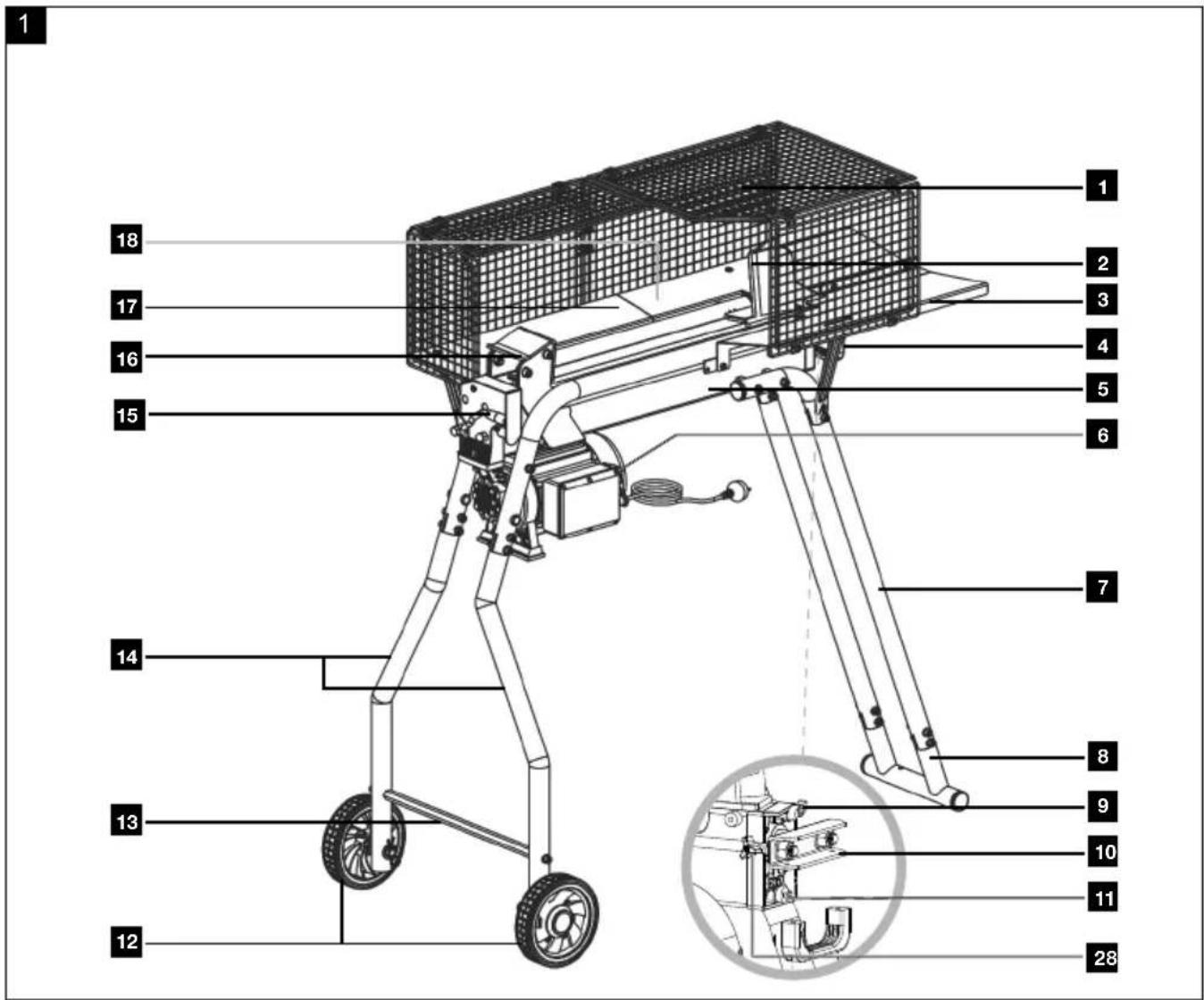
2. Product description (Fig. 1)
- Protective cage
- Riving knife
- Tray table 3
- Handle
- Cylinder
- Release button
-
rear legs
-
Foot
- Ventilation screw
- U-bow
- Oil drain screw with oil dipstick
- Transport wheels
- Cross member
- front legs
- Control lever
- Pressure plate
- Tray table 1
- Tray table 2
- Support bracket 1
- Support bracket 2
- Support bracket 3
- Protective grid left
- Protective grid top 1
- Protective grid rear 1
- Protective grid top 2
- Protective grid front
- Protective grid rear 2
- Stroke limitation ring
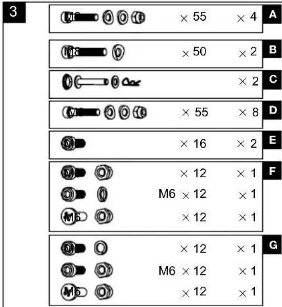
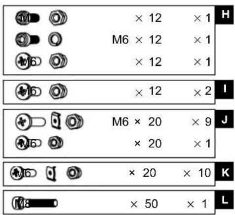
A. Allen screw M8x55 mm + washer + nut M8
B. Allen screw M8x50 mm + washer
C. Wheel cap + wheel bolt + washer + safety pin
D. Allen screw M8x55 mm + washer + nut M8
E. Allen screw M6x16 mm
F. Allen screw M6x12 mm + Phillips screw M6x12 mm + locknut M6 + spring washer
G. Allen screw M6x12 mm + Phillips screw M6x12 mm + locknut M6 + spring washer
H. Allen screw M6x12 mm + Phillips screw M6x12 mm + locknut M6 + spring washer
I. Phillips screw M6x12 mm + nut M6
J. Phillips screw M6x20 mm + clamping clip + nut M6
K. Phillips screw M6x20 mm + clamping clip + nut M6
L. Allen screw M8x50 mm (pre-fit)
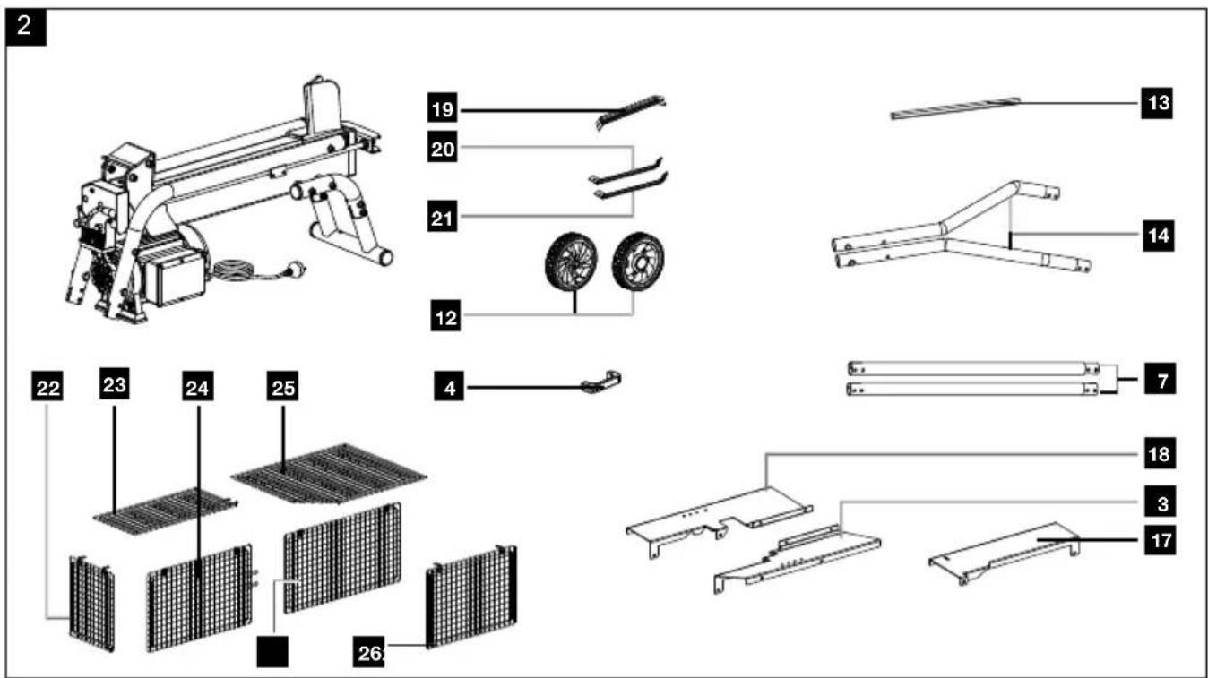
3. Scope of delivery
Item Quantity Designation
| 3. 1x | Tray table 3 | |
| 4. 1x | Handle | |
| 7. 2x | rear legs | |
| 8. 1x | Foot | |
| 12. | 2x | Transport wheels |
| 13. | 1x | Cross member |
| 14. | 2x | front legs |
| 17. 1x Tray table 1 |
| 18. 1x Tray table 2 |
| 19. 1x Support bracket 1 |
| 20. 1x Support bracket 2 |
| 21. 1x Support bracket 3 |
| 22. 1x Protective grid left |
| 23. 1x Protective grid top 1 |
| 24. 1x Protective grid rear 1 |
| 25. 1x Protective grid top 2 |
| 26. 1x Protective grid front |
| 27. 1x Protective grid rear 2 |
| 1x Log splitter |
| 1x Operating manual |
4. Proper use
The log splitter is designed exclusively for chopping firewood in the direction of the grain.
The product may only be used in the intended manner. Any use beyond this is improper. The user/operator, not the manufacturer, is responsible for damages or injuries of any type resulting from this.
An element of the intended use is also the observance of the safety instructions, as well as the assembly instructions and operating information in the operating manual.
Persons who operate and maintain the product must be familiar with the manual and must be informed about potential dangers.
The liability of the manufacturer and resulting damages are excluded in the event of modifications of the product.
The product may only be operated with original parts and original accessories from the manufacturer.
The safety, operating and maintenance specifications of the manufacturer, as well as the dimensions specified in the technical data, must be observed.
Please note that our products were not designed with the intention of use for commercial or industrial purposes. We assume no guarantee if the product is used in commercial or industrial applications, or for equivalent work.
The manufacturer is not liable for damage caused by improper use or incorrect operation.
Explanation of the signal words in the operating manual
DANGER
Signal word to indicate an imminently hazardous situation which, if not avoided, will result in death or serious injury.
⚠ WARNING
Signal word to indicate a potentially hazardous situation which, if not avoided, could result in death or serious injury.
CAUTION
Signal word to indicate a potentially hazardous situation which, if not avoided, could result in minor or moderate injury.
ATTENTION
Signal word to indicate a potentially hazardous situation which, if not avoided, could result in product or property damage.
5. General safety instructions
⚠ WARNING - Read all safety information, instructions, illustrations and technical data for this product.
Failure to follow all instructions listed below may result in electric shock, fire and/or serious injury.
Save all warnings and instructions for future reference.
The term “power tool” used in the safety instructions refers to mains-powered power tools (with a mains cable) and battery-powered power tools (without a mains cable).
Warning! This power tool generates an electromagnetic field during operation. This field can impair active or passive medical implants under certain circumstances.
In order to prevent the risk of serious or deadly injuries, we recommend that persons with medical implants consult with their physician and the manufacturer of the medical implant prior to operating the power tool.
△ WARNING: When using power tools, the basic safety precautions below must be followed in order to reduce the risk of fire, electric shock, and personal injury. Please read all instructions before working with this tool.
- Observe all safety information and danger notices on the machine.
- Ensure that all of the safety information and danger notices on the machine are complete and in legible condition.
- The safety equipment on the machine must not be disassembled or made unusable.
- Check mains connection cables. Do not use faulty connection cables.
- Check for correct function of the two-hand control before commissioning.
- The operating personnel must be at least 18 years of age. Trainees must be at least 16 years of age and may only work on the machine under supervision.
• Children may not work with this product. - Wear work gloves and safety shoes, safety goggles, close-fitting work clothes, and hearing protection (PPE) while working.
- Caution when working: Danger of injury for fingers and hands due to the splitting tool.
- Modification, adjustment and cleaning work, as well as maintenance and rectification of faults may only be carried out when the engine is switched off. Pull out the mains plug!
• Installation, repairs and maintenance work on the electrical equipment may only be carried out by electricians. - All protective and safety equipment must be reassembled immediately after repair, maintenance is completed.
- Switch off the engine when leaving the work station. Pull out the mains plug!
- Removing or working without guards is prohibited.
- When splitting, the properties of the wood (e.g. growths, trunk slices of irregular shape, etc.) can result in hazards such as ejecting parts, splitter blocking, and crushing.
6. Additional safety instructions
- The log splitter may only be operated by a single person.
- Never split trunks that contain nails, wire, or other objects.
- Wood that has already been split and wood chippings create a hazardous work area. There is a danger of tripping, slipping or falling. Always keep the work area orderly.
- Never place your hands on moving parts of the machine when it is switched on.
- Only split wood with a maximum length of 52 cm.
7. Residual risks
The product has been built according to state-of-the-art and the recognised technical safety rules. However, individual residual risks can arise during operation.
• Health hazard due to electrical power, with the use of improper electrical connection cables.
- Danger of injury for fingers and hands from the splitting tool in the event of improper guiding or support of the wood.
- Injuries due to the workpiece being ejected at high speed due to improper holding or guiding.
• Health hazard due to electrical power, with the use of improper electrical connection cables.
- Before performing setting or maintenance work, release the start button and pull out the mains plug.
• Furthermore, despite all precautions having been met, some non-obvious residual risks may still remain.
- Residual risks can be minimised if the "Safety Instructions" and the "Intended Use" together with the operating manual as a whole are observed.
- Avoid accidental starting of the machine: the operating button may not be pressed when inserting the plug in an outlet. Use the tool that is recommended in this operating manual. This is how to ensure that your machine provides optimum performance.
- Keep your hands away from the working area when the machine is in operation.
8. Technical data
Dimensions L x W x H 1235 x 610 x 1345 mm
Wood ∅ min - max 50 mm - 250 mm
Wood length min - max 200 mm - 520 mm
Weight with base frame 57.4 kg
| Engine 220 - 240V~ 50 Hz | |
| Rated input P1 2200 W | |
| Rated input P2 1700 W | |
| Operating mode S3* 25% | |
| Splitting force max. 5 t | |
| Cylinder stroke 360 mm | |
| Cylinder forward stroke 3.7 cm/s | |
| Cylinder reverse stroke 6.17 cm/s | |
| Oil quantity | 3.5 l |
| Operating pressure | 206 bar |
| Speed | 2800 rpm |
| Degree of protection | IP 54 |
Subject to technical changes!
* Operating mode S3 25% = periodical intermediate duty with a duty cycle of 25% (2.5 min based on a 10 minute period)
Noise and vibration
⚠ Warning: Noise can have serious effects on your health. If the machine noise exceeds 85 dB, please wear suitable hearing protection.
The noise and vibration values have been determined through a standardised measurement process.
Noise data
| Sound power level L_WA | 96 dB |
| Sound pressure level L_pA | 89.9 dB |
| Uncertainty K_wa/pA | 3 dB |
9. Unpacking
- Open the packaging and carefully remove the product.
- Remove the packaging material, as well as the packaging and transport safety devices (if present).
- Check whether the scope of delivery is complete.
- Check the product and accessory parts for transport damage. In the event of complaints the carrier must be informed immediately. Later claims will not be recognised.
-
If possible, keep the packaging until the expiry of the warranty period.
-
Familiarise yourself with the product by means of the operating manual before using for the first time.
- With accessories as well as wearing parts and replacement parts use only original parts. Spare parts can be obtained from your specialist dealer.
- When ordering please provide our article number as well as type and year of manufacture for the product.
⚠ WARNING!
The product and the packaging material are not children's toys! Do not let children play with plastic bags, films or small parts! There is a danger of choking or suffocating!
10. Assembly
Place the product on a level, even surface.
Tool required:
- Allen key, 5 mm*
- Allen key, 6 mm*
- Open-ended spanner, AF 10*
- Open-ended spanner, AF 13*
• Phillips screwdriver* - Needle nose pliers*
^* = may not be included in the scope of delivery!
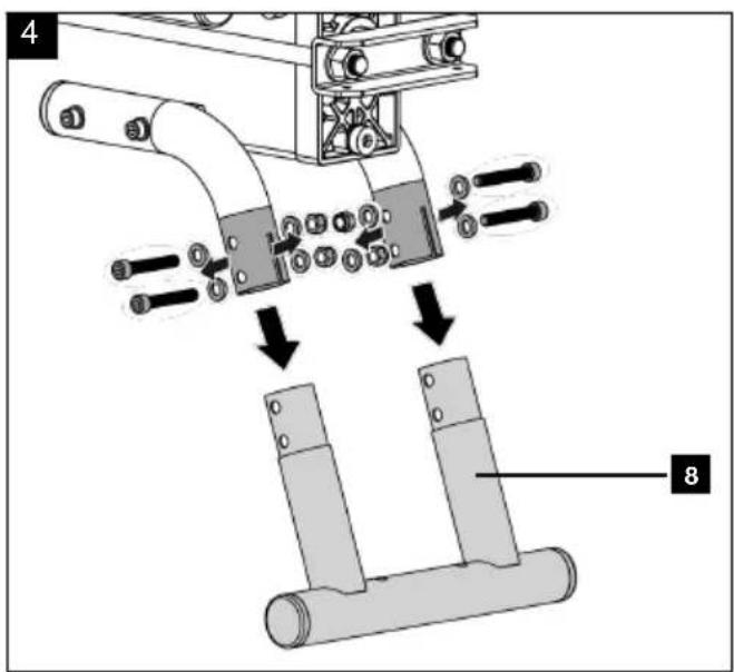
10.1 Machine stand assembly (Fig. 4 - 10)
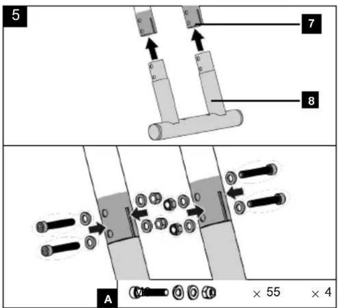
- Loosen the pre-mounted nuts M8, the Allen screws M8x55 mm and the washers (A) to disassemble the foot (8). Use an Allen key AF 6* and an open-ended spanner AF 13*.
- Push the foot (8) into the openings of the two rear legs (7) and align the mounting holes.
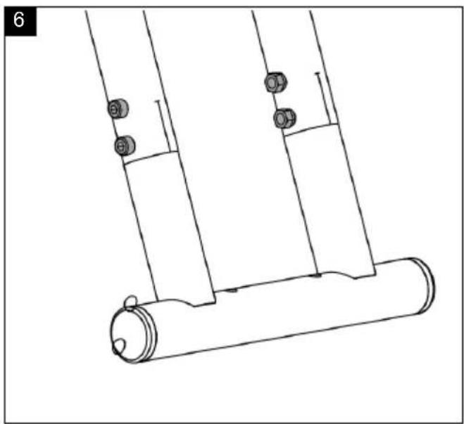
- Fit the foot (8) to the rear legs (7) using the nuts M8, Allen screws M8x55 mm and washers (A) that were removed earlier. Use an Allen key AF 6* and an open-ended spanner AF 13*.
- Align the mounting holes of the two front legs (14) with the mounting holes of the cross member (13).
- Fit the cross member (13) between the two front legs (14).
- Use the Allen screws M8x50 mm, the two washers (B) and an Allen key AF 6*.
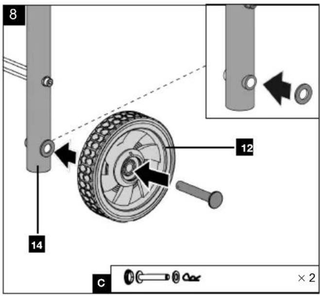
- Align the transport wheel (12) with the mounting hole on the front leg (14).
- Now insert a washer (C) between the transport wheel (12) and the front leg (14).
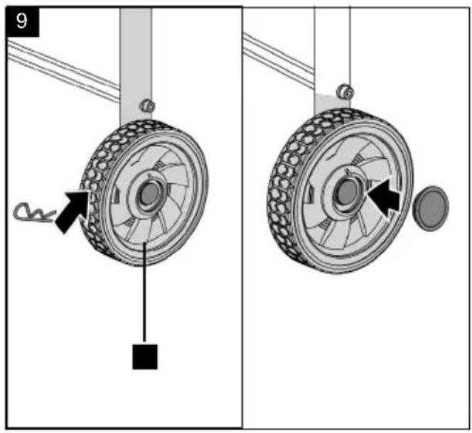
- Secure the connection with the wheel bolt and the safety pin, then place the wheel cap (C) on
the transport wheel (12). If necessary, use needle-nose pliers*.
- Repeat the process with the other transport wheel (12).
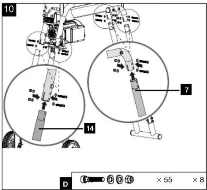
- Now connect the two front and rear legs (14/7) to the mountings on the main unit and secure the connections with the Allen screws M8x55 mm, washers and nuts M8 (D). Use an Allen key AF 6* and an open-ended spanner AF 13*.
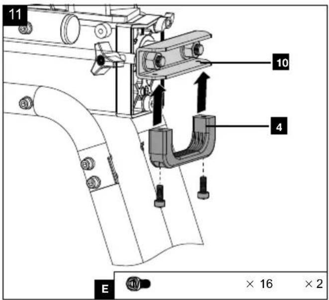
10.2 Fitting the handlebar (4) (Fig. 11)
- Fasten the handle (4) to the U-bow (10) with two Allen screws M6x16 mm (E). Use an Allen key AF 5*.
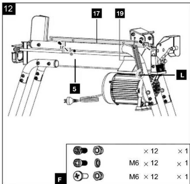
10.3 Installation of tray table 1 (17) (Fig. 12)
- Stand behind the product.
- Align the right-hand outer mounting hole of the tray table 1 (17) with the mounting hole on the cylinder cover (5) and fit the Allen screw M6x12 mm with the spring washer (F). Use an Allen key AF 5*.
- Secure the left mounting hole of the tray table 1 (17) to the connecting plate of the tube rail using an Allen screw M6x12 and a locknut M6 (F). Use an Allen key AF 5* and an open-ended spanner AF 10*.
- Loosen the Allen screw M8x50 mm (L) without removing it. Use an Allen key 6 mm* for this.
- Place the support bracket 1 (19) with the open side between the washer and the frame tube.
- Align the mounting holes of the tray table 1 (17) and the support bracket 1 (19) and install the Phillips screw with the locknut M6 (F). Use a Phillips screwdriver* and an open-ended spanner AF 10*.
- Tighten the Allen screw M8x50 mm (L) again using the Allen key AF 6*.
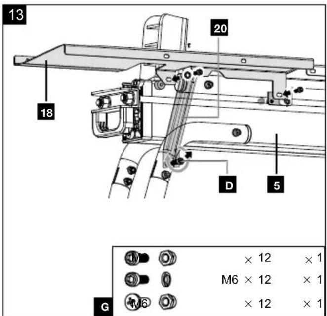
10.4 Installation of tray table 2 (18) (Fig. 13)
- Stand behind the product.
- Align the mounting holes of the tray table 2 (18) as shown in the illustration.
- Mount the left side of the tray table 2 (18) to the cylinder (5) using the Allen screw M6x12 mm and the spring washer (G). Use an Allen key 5 mm* for this.
- Secure the right mounting hole of the tray table 2 (18) to the connecting plate of the tube rail using an Allen screw M6x12 and a locknut M6 (G). Use an Allen key AF 5* and an open-ended spanner AF 10*.
-
Loosen the Allen screw M8x55 mm (D) on the mounting of the rear leg (7) without removing it. Use the enclosed Allen key AF 6 and an open-ended spanner AF 13*.
-
Place the support bracket 2 (20) with the open side between the washer and the frame tube.
- Align the mounting holes of the tray table 2 (18) and the support bracket 2 (20) and install the Phillips screw with the locknut M6 (G). Use a Phillips screwdriver* and an open-ended spanner AF 10*.
- Tighten the Allen screw M8x55 mm (D) again using the Allen key AF 6* and the open-ended spanner AF 13*.
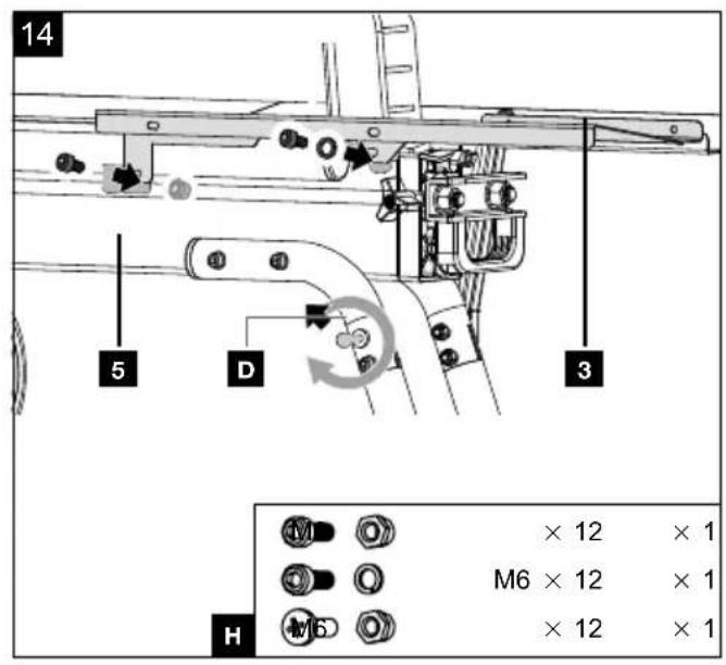
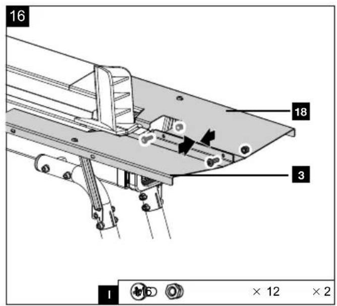
10.5 Installation of tray table 3 (3) (Fig. 14 - 16)
- Stand in front of the operating side of the product.
- Align the mounting holes of the tray table 3 (3) as shown in the illustration.
- Mount the right side of the tray table 3 (3) to the cylinder (5) using the Allen screw M6x12 mm and the spring washer (H). Use an Allen key 5 mm* for this.
- Secure the left mounting hole of the tray table 3 (3) to the connecting plate of the tube rail using an Allen screw M6x12 and a locknut M6 (H). Use an Allen key AF 5* and an open-ended spanner AF 10*.
- Loosen the Allen screw M8x55 mm (D) on the mounting of the rear leg (7) without removing it. Use the enclosed Allen key AF 6* and an open-ended spanner AF 13*.
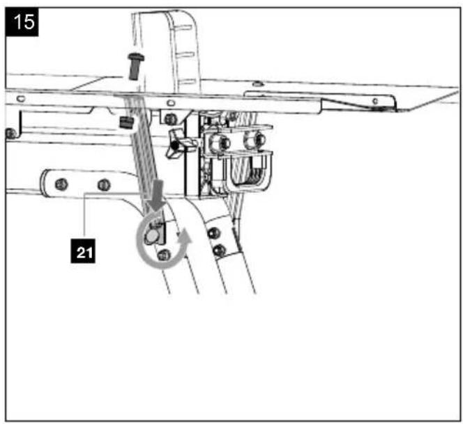
- Place the support bracket 3 (21) with the open side between the washer and the frame tube.
- Align the mounting holes of the tray table 3 (3) and the support bracket 3 (21) and install the Phillips screw with the locknut M6 (H). Use a Phillips screwdriver* and an open-ended spanner AF 10*.
- Tighten the Allen screw M8x55 mm (D) again using the Allen key AF 6* and the open-ended spanner AF 13*.
- Connect tray table 2 (18) and set-down table 3 (3) with two Phillips screws M6 and the lock nuts M6 (I). Use a Phillips screwdriver* and an open-ended spanner AF 10*.
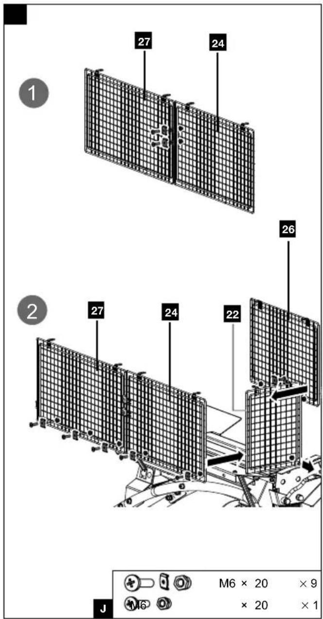
10.6 Fitting the protective cage (Fig. 17/18)
- Connect the rear protective grids (24/27) to each other and secure them with two Phillips screws M6x20 mm, clamping clips and nuts M6 (J). Use a Phillips screwdriver* and an open-ended spanner AF 10* for this.
-
Attach the guards (24/27) to the holes provided on the side of tray table 1 (17) and tray table 2 (18). Use the Phillips screws M6x20 mm, the clamping clips and the nuts M6 (J) as well as a Phillips screwdriver* and an open-ended spanner AF 10* for this.
-
Secure the left protective grid (22) with the Phillips screws M6x20 mm, clamping clips and nuts M6 (J) to the holes provided on the tray table 1 (17). Use a Phillips screwdriver* and an open-ended spanner AF 10* for this.
-
Secure the front protective grid (26) to the tray table 3 (3) using the Phillips screws M6x20 mm, clamping clips and nuts M6 (J).
-
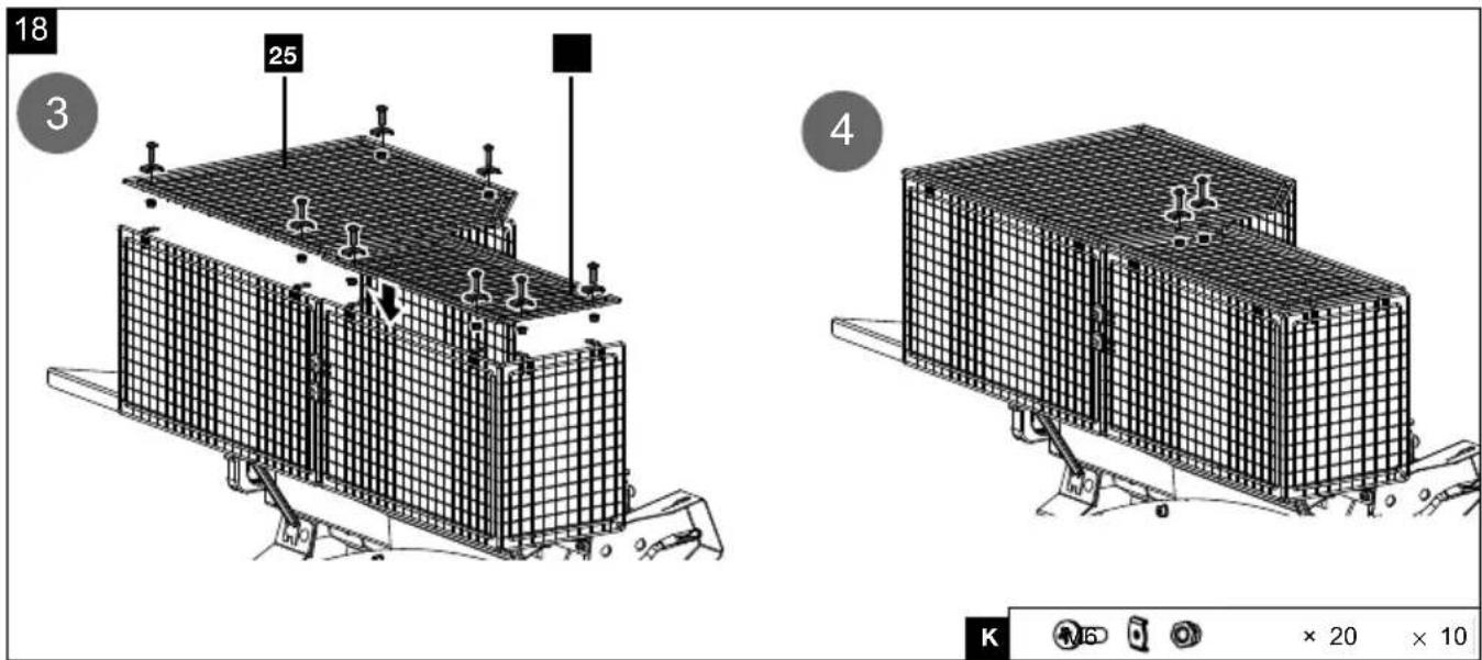
Fit the protective grid (22) to the guard of the adjustment lever (15) using a Phillips screw M6x20 mm and a nut M6 (K). Use a Phillips screwdriver* and an open-ended spanner AF 10* for this.
-
Now attach the upper protective grids (23/25) to the upper side. Secure it with the Phillips screws M6x20 mm, the clamping clamps and nuts M6 (J). Use a Phillips screwdriver* and an open-ended spanner AF 10* for this.
-
Connect the upper protective grids (23/25) to each other by using two Phillips screws M6x20 mm, clamping nuts and nuts M6 (J).
-
Finally, tighten up all the screws.
11. Start-up
⚠ Attention!
Always make sure the product is fully assembled before commissioning!
⚠ Attention!
Before performing setting or maintenance work, unplug the mains plug!
NOTE!
Product damage
If the product is operated without or with too little hydraulic oil, this can lead to hydraulic pump damage.
NOTE!
Environmental damage!
Spilled oil can pollute the environment permanently.
The liquid is highly toxic and can quickly lead to water pollution.
- Fill/empty oil only on level, paved surfaces.
- Use a filling nozzle or funnel.
- Collect drained oil in a suitable container.
- Wipe up spilled oil carefully immediately and dispose of the cloth according to local regulations.
- Dispose of oil as per local regulations.
Before each use, always check:
- the connection cables for defective areas (cracks, cuts and the like),
• The device for possible damage,
• whether all screws are tightened,
• The hydraulic system for leaks, - the oil level,
• The safety devices and
• The ON/OFF switch.
Place the product on a level, even surface.
Tool required:
- Allen key, 5mm*
- Allen key, 8mm*
- Cloth*
- Funnel*
* = may not be included in the scope of delivery!
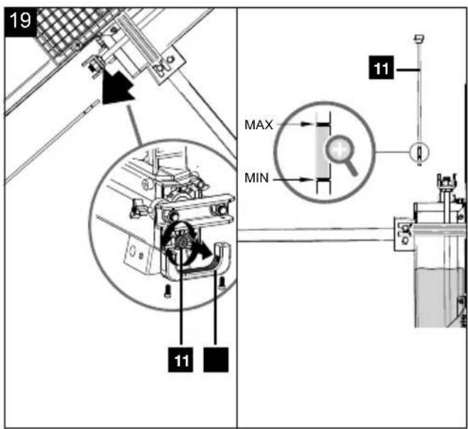
11.1 Checking the oil level (Fig. 19)
⚠ Attention!
Check the oil level prior to commissioning.
The hydraulic system is a closed system with an oil tank, oil pump and control valve. There is already oil in the system when delivered. Check the oil level before the initial commissioning and regularly before commissioning. An oil level that is too low can damage the oil pump, refill with oil if necessary.
Note
The cylinder rod must be retracted before the check, the product must be level.
- Pull out the mains plug and position the log splitter vertically so that the oil drain screw with oil dipstick (11) is aligned vertically upwards.
- Remove the handle (4) from the U-bow (10) by loosening the Allen screws M6x16 mm (E). Use an Allen key AF 5*.
- Remove the oil drain screw with oil dipstick (11) using an Allen key AF 8*.
- Wipe the oil dipstick with a clean, lint-free cloth*.
- Reinsert the oil drain screw with oil dipstick (11) and turn it completely in.
- Remove the oil drain screw with oil dipstick (11) again.
- The oil level must be within the middle mark on the oil dipstick.
-
Reinsert the oil drain screw with oil dipstick (11) and tighten it using an Allen key AF 8*.
-
Fasten the handle (4) to the U-bow (10) with two Allen screws M6x16 mm (E).
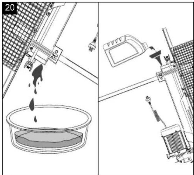
11.2 Topping up the hydraulic oil (Fig. 19/20)
-
Pull out the mains plug and position the log splitter vertically so that the oil drain screw with oil dipstick (11) is aligned vertically upwards.
-
Remove the handle (4) from the U-bow (10) by loosening the Allen screws M6x16 mm (E).
-
Remove the oil drain screw with oil dipstick (11) using an Allen key AF 8*.
-
Carefully top up the hydraulic oil (max. 3.5 l) using a suitable funnel* or filling nozzle when the oil level is not within the middle mark on the oil dipstick. Do not overfill the hydraulic oil.
-
Reinsert the oil drain screw with oil dipstick (11) and tighten it using an Allen key AF 8*.
-
Fasten the handle (4) to the U-bow (10) with two Allen screws M6x16 mm (E).
12. Working instructions
⚠ WARNING!
Danger of crushing!
The area behind the pressure plate (16) must be kept free of wood residues at all times. There is an increased danger of crushing!
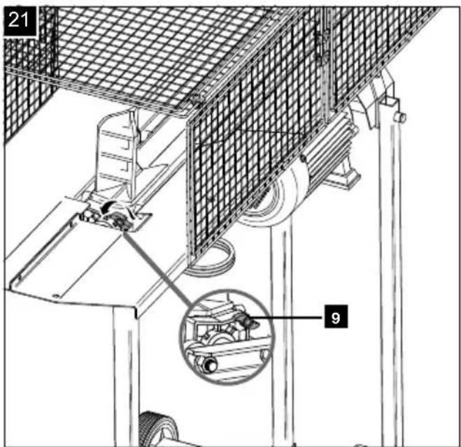
12.1 Ventilation screw (9) (Fig. 21)
Before starting any work, it is essential to loosen the ventilation screw (9) by a few turns to ensure air circulation in the oil tank. If it remains tightened while working, the hydraulic movement leads to overpressure which can damage your log splitter!
Attention:
- Before transporting the product, it is essential to tighten the ventilation screw (9) to prevent oil leakage.
- At low temperatures, allow the splitter to idle for 5 mins. until the oil has heated up accordingly.
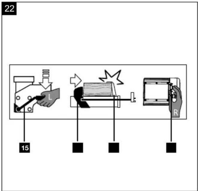
12.2 Switching on/off (Fig. 22)
Your log splitter is equipped with a two-hand control system. The left hand operates the operating lever (15), the right hand operates the release button (6). Releasing both control parts causes the pressure plate (16) to retract. If the release button (6) is switched off and the operating lever (15) is actuated, the pressure plate (16) remains at the current position.
-
Plug the mains plug into the socket.
-
When laying the power supply cable, ensure that it is not led over the pressure plate (16) or near the riving knife (2). Also avoid places where there is a danger of damage or tearing.
-
Position the wooden block on the support guide. The guides hold the wooden block in the centre of the riving knife. If the wooden block does not fit well or "snugly", it must be turned.
-
Press the operating lever (15) downwards with the left hand and initiate the splitting process by pressing the release button (6) with the right hand.
-
The pressure plate (16) moves forwards and pushes the wood through the riving knife (2).
12.2.1 Thermal protection
With overloading or overheating, the protective shut-down integrated in the product switches off for safety reasons.
-
Wait approx. 15 minutes until the motor has cooled down.
-
Restart the product.
12.3 Splitting logs
⚠ WARNING!
Danger of injury!
Dry and seasoned wood can explode during the splitting process and injure the operator in the face. During the splitting process, bruising or severing of body parts may occur due to retracting of the riving knife. Pieces of wood that are produced during a splitting process can fall down.
Wear appropriate personal protective equipment.
Make sure that the wood to be split does not contain nails or foreign objects. The end of the log must be cut straight. Branches must be sawn off flush. Pieces of wood cut at an angle can slip away during the splitting process! Only split timbers that have been sawn off straight. To do this, proceed as follows:
-
Place the log to be split straight on the support surface.
-
Now operate the operating lever (15) with your left hand and the release button (6) with your right hand.
-
Press the operating lever (15) downwards and initiate the splitting process by pressing the release button (6).
-
If the release button (6) is switched off and the operating lever (15) is actuated, the pressure plate (16) remains at the current position.
Releasing both control parts causes the pressure plate (16) to retract.
- Now, shorten the return of the pressure plate (16) by fixing it in the desired position using the star grip screw on the stroke limitation ring (28).
If a piece of log to be split cannot be split within 5 seconds, stop the process immediately. The log is probably too hard for the capacity of your log splitter. Turn the log 90° and try again.
Note:
Continuous operation for more than 5 seconds can pose a risk of overheating. Your product may become damaged.
12.4 Stroke limitation (Fig. 1)
If the log is short, it makes sense to limit the stroke of the pressure plate (16).
- Press the control lever (15) and the release button (6) and move the pressure plate (16) until just in front of the log.
- Release the release button (6).
- Place the stroke limitation ring (28) at the desired position where the pressure plate (16) should remain by loosening the star grip screw.
- Re-tighten the star grip screw.
- You can then release the control lever (15).
- The pressure plate (16) now remains in the set position when splitting.
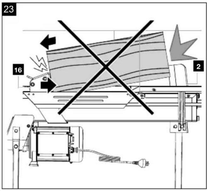
12.5 Faulty loading (Figs. 23 - 25)
Attention!
Danger of injury!
Never split multiple pieces at the same time! There is a danger that one of the parts may be flung uncontrollably from the machine.
- Always place the log flat on the support surface! It must not slip or be placed at an angle. The riving knife (2) will be overstressed if a splitting process does not take place across the entire cutting edge, but only in the upper area.
- The log must always rest firmly on the guides and on the support surface. Make sure that the log does not rotate while splitting and cannot jump up or slip.
- Do not overload the riving knife (2) by force splitting at the top end. This can lead to breaking of the riving knife or damage to the log splitter.
• Always split the log in the direction of the wood fibre.
- Never place wood in the log splitter crossways. This can be dangerous and/or seriously damage the log splitter.
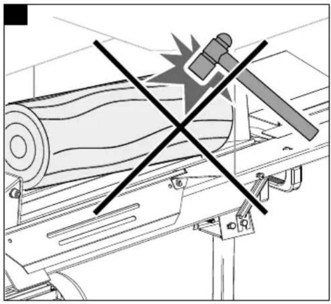
12.6 Wedged logs (Fig. 23 + 25)
ATTENTION!
Danger of injury!
There is a danger of knotty logs becoming jammed during the splitting process. Please note that the wood is under a lot of tension when it is removed and your fingers can be crushed in the split crack.
- Do not reach into the log splitter when it is running.
- Do not put any objects into the log splitter while it is running (e.g. hammer or similar).
Never try to knock or saw wedged logs out of your log splitter. This can lead to accidents and damage to the product.
Proceed as follows:
- Release the control lever (15) and the release button (6) in order to move the pressure plate (16) back into the start position.
- Place a wedge under the log.
- Trigger a splitting process so that the pressure plate (16) pushes the wedge far below the log to be removed.
- Repeat the above steps with new wedges until the log is pushed up and out of the log splitter.
13. Transport (Fig. 26)
⚠ Attention!
Disconnect the mains plug before transport.
The log splitter is equipped with two transport wheels (12) and a handle (4) for easy transport. In order to transport the product, hold the handle (4) of the log splitter with one hand and raise it forwards from the floor. This makes it easy to transport the log splitter. Before transporting the product, the ventilation screw (9) must be tightened to prevent oil leakage.
14. Maintenance
⚠ WARNING!
Danger of injury!
The product can start unexpectedly and cause injuries.
- Switch the motor off before performing any maintenance work.
- Disconnect the mains plug before carrying out any maintenance work.
⚠ WARNING!
Health hazard!
Inhalation of oil vapours and exhaust gases can cause serious damage to health, unconsciousness and in extreme cases death.
- Do not breathe in oil vapours and exhaust gases.
- Operate the product outdoors only.
NOTE!
Product damage
If the product is operated without or with too little hydraulic oil, this can lead to product damage.
NOTE!
Environmental damage!
Spilled oil can pollute the environment permanently. The liquid is highly toxic and can quickly lead to water pollution.
- Fill/empty oil only on level, paved surfaces.
- Use a filling nozzle or funnel.
- Collect drained oil in a suitable container.
- Wipe up spilled oil carefully immediately and dispose of the cloth according to local regulations.
- Dispose of oil as per local regulations.
Our recommendation to you:
- The riving knife is a wearing part that must be re-sharpened if necessary.
- The combined two-hand protective device must remain smooth-running. Lubricate with a few drops of oil as required.
• Always keep the support surface clean.
• Lubricate the slider rails with a little grease.
Check the oil level regularly!
An oil level that is too low will damage the oil pump! Check the hydraulic connections and screw connections for leaks regularly and retighten them if necessary.
We recommend oil from the HLP 32 range.
When do I change the oil?
Change the oil after 150 working hours.
Tool required:
- Allen key, 5mm*
- Allen key, 8mm*
• Collection bucket*
- Funnel*
^* = may not be included in the scope of delivery!
14.1 Changing the hydraulic oil (Fig. 19/20)
-
Pull out the mains plug and position the log splitter vertically.
-
Remove the handle (4) from the U-bow (10) by loosening the Allen screws M6x16 mm (E). Use an Allen key 5 mm* for this.
-
Place a suitable collection bucket* under the oil drain screw with oil dipstick (11).
-
Remove the oil drain screw with oil dipstick (11) using an Allen key AF 8*.
-
Drain the hydraulic oil mixture completely.
-
Carefully top up the hydraulic oil (about 3.5 l) using a suitable funnel or filling nozzle. Do not overfill the hydraulic oil.
-
Check the oil level. Wipe the oil dipstick (11) with a clean, lint-free cloth.
-
Reinsert the oil drain screw with oil dipstick (11) and turn the oil drain screw with oil dipstick (11) back in again fully.
-
Remove the oil drain screw with oil dipstick (11) again.
-
The oil level must be within the middle mark on the oil dipstick. Top up with a little hydraulic oil if necessary.
-
Reinsert the oil drain screw with oil dipstick (11) and tighten it using an Allen key AF 8*.
-
Air can get into the hydraulic system after changing the hydraulic oil. Therefore, actuate the log splitter while idle several times.
Note: It is necessary to loosen the ventilation screw (9) by a few turns to ensure air circulation in the oil tank.
-
Then recheck the oil level and top up the hydraulic oil if necessary.
-
Fasten the handle (4) to the U-bow (10) with two Allen screws M6x16 mm (E). Use an Allen key 5 mm* for this.
15. Electrical connection
The electrical motor installed is connected and ready for operation. The connection complies with the applicable VDE and DIN provisions.
The customer's mains connection as well as the extension cable used must also comply with these regulations.
Use a portable safety switch (PRCD) if the residual current protective circuit (RCD) in the mains power supply is not provided with a rated residual current of no more than 0.03 A.
Damaged electrical connection cable
The insulation on electrical connection cables is often damaged.
This may have the following causes:
- Pressure points, where connection cables are passed through windows or doors.
- Kinks where the connection cable has been improperly fixed or routed.
- Places where the connection cables have been cut due to being driven over.
- Insulation damage due to being ripped out of the wall outlet.
- Cracks due to the insulation ageing.
Such damaged electrical connection cables must not be used and are life-threatening due to the insulation damage.
Check the electrical connection cables for damage regularly. Ensure that the connection cables are disconnected from electrical power when checking for damage.
Electrical connection cables must comply with the applicable VDE and DIN provisions. Only use connection cables of the same designation.
The printing of the type designation on the connection cable is mandatory.
For single-phase AC motors, we recommend a fuse rating of C 16A or K 16A for products with a high starting current (from 3000 watts)!
- The product fulfils the requirements of EN 61000-3-11 and is subject to special connection requirements. This means that use at any freely selectable connection points is not permitted.
- The product can cause temporary voltage fluctuations in unfavourable mains conditions.
- The product is only intended for use at connection points that a) do not exceed a maximum permissible mains impedance "Z" (Zmax. = 0.128 Ω), or b) have a mains constant current carrying capacity of at least 100 A per phase.
- As the user, you are required to ensure that the connection point at which you wish to operate the product fulfils one of the requirements mentioned, a) or b). If necessary, consult with your energy supplier in this regard.
AC motor 220 - 240 V\~ / 50 Hz
Mains voltage 220 - 240 V\~ / 50 Hz
Mains power connection and extension leads must be 3-core = P + N + SL - (1/N/PE). An extension cable with too small a conductor cross-section causes a significant reduction in the performance of the device.
Cables up to 25 m long must have a cross section of at least 3 x 1.5 mm ^2 , cables over 25 m long must have a cross section of at least 2.5 mm ^2 . The mains power connection must be protected with a max. 16 A fuse.
16. Cleaning
⚠ WARNING!
Danger of injury!
The product can start unexpectedly and cause injuries.
- Switch the motor off before performing any maintenance work.
- Disconnect the mains plug before carrying out any maintenance work.
NOTE!
Risk of damage!
Damage to the motor can occur if water penetrates into the motor unit.
- Clean the product with a brush.
- Do not immerse the product in water or other liquids and do not spray the motor unit with a high-pressure cleaner.
We recommend that you clean the product directly after every use. Clean the product at regular intervals using a damp cloth and a little soft soap.
Do not use any cleaning products or solvents; they could attack the plastic parts of the product. Make sure that no water can penetrate the interior of the product.
17. Storage
Store the product and its accessories in a dark, dry and frost-free place that is inaccessible to children.
The optimum storage temperature lies between 5 and 30 °C.
Store the product in its original packaging. Cover the product to protect it from dust or moisture. Store the operating manual with the product.
18. Repair & ordering spare parts
After repairs or maintenance, make sure that all safety-related parts are installed and are in perfect condition.
All parts which may cause injury must be kept where they are inaccessible to children or others.
Attention: According to the German Product Liability Act, no liability is accepted for damage caused by improper repairs or by not using original spare parts.
Such work should be performed by a customer service centre or an authorised specialist. The same applies to accessory parts.
Spare parts and accessories can be obtained from our Service Centre. To do this, scan the QR code on the front page.
Connections and repairs
Connections and repair work on the electrical equipment may only be carried out by electricians.
Please provide the following information in the event of any queries:
• Type of current for the motor
• Machine data - type plate
- Motor data - type plate
Important note in the case of repairs:
For return delivery of the product for repair, please ensure for safety reasons that it is free of oil and fuel when it is sent to the service centre.
18.1 Ordering spare parts
Please provide the following information when ordering spare parts:
- Model designation
- Item number
- Type plate data
Spare parts / accessories Article no.:
Plastic glides 3905202013
Plastic glides at the bottom 3905202012
Hydraulic oil 16020280
Hydraulic oil Vg Valentina 16020281
18.2 Service information
With this product, it is necessary to note that the following parts are subject to natural or usage-related wear, or that the following parts are required as consumables.
Wearing parts*: Hydraulic oil, riving knife
* may not be included in the scope of delivery!
19. Disposal and recycling
Notes for packaging


The packaging materials are recyclable. Please dispose of packaging in an environmentally friendly manner.
Notes on the electrical and electronic equipment act (ElektroG)
Waste electrical and electronic equipment does not belong in household waste, but must be collected and disposed of separately!
- Used batteries or rechargeable batteries that are not installed permanently in the old device must be removed non-destructively before disposal! Their disposal is regulated by the battery act.
- Owners or users of electrical and electronic devices are legally obliged to return them after use.
- The end user is responsible for deleting their personal data from the old device being disposed of!
- The symbol of the crossed-out dustbin means that waste electrical and electronic equipment must not be disposed of with household waste.
- Waste electrical and electronic equipment can be handed in free of charge at the following places:
- Public disposal or collection points (e.g. municipal works yards).
- Points of sale of electrical devices (stationary and online), provided that dealers are obliged to take them back or offer to do so voluntarily.
- Up to three waste electrical devices per type of device, with an edge length of no more than 25 centimetres, can be returned free of charge to the manufacturer without prior purchase of a new device from the manufacturer or taken to another authorised collection point in your vicinity.
- Further supplementary take-back conditions of the manufacturers and distributors can be obtained from the respective customer service.
- If the manufacturer delivers a new electrical device to a private household, the manufacturer can arrange for the free collection of the old electrical device upon request from the end user. Please contact the manufacturer's customer service for this.
• These statements only apply to devices installed and sold in the countries of the European Union and which are subject to the European Directive 2012/19/EU. In countries outside the European Union, different regulations may apply to the disposal of waste electrical and electronic equipment.
You can find out how to dispose of the disused device from your local authority or city administration.
Fuels and oils
- Before disposing of the device, the fuel tank and the engine oil tank must be emptied!
- Fuel and engine oil do not belong in household waste or drains, but must be collected or disposed of separately!
- Empty oil and fuel tanks must be disposed of in an environmentally friendly manner.
20. Troubleshooting
The following table shows fault symptoms and describes remedial measures in the event of your product failing to work properly. If you cannot localise and rectify the problem with this, please contact your service workshop.
| Fault Possible cause Remedy | ||
| The engine ends the splitting process automatically. | Overvoltage protective device was triggered. | Call a qualified electrician. |
| Log is not split. | Log splitter loaded incorrectly. | Insert the log correctly. |
| Size of log exceeds motor capacity. | Saw logs into a more suitable size. | |
| Riving knife is blunt. | Grind the riving knife. | |
| Oil leaks. | Locate the leak, contact the dealer. | |
| Pressure plate vibrates, makes noise. | Low oil and excess air in the hydraulic system. | Check the oil level, top up if necessary, otherwise contact the dealer. |
| Hydraulic pump whistles. | Too little hydraulic oil. Top up oil. | |
| Oil leaks on the cylinder or in other places. | Trapped air in the hydraulic system during operation. | Loosen the bleeder screw a few turns before use. |
| Bleeder screw not tightened before transport. | Tighten the bleeder screw firmly before transport. | |
| Oil drain screw loose. Tighten the oil drain screw firmly. | ||
| Oil valve and/or seals defective. Contact dealer. | ||
Günzburger Straße 69
D-89335 Ichenhausen
Cher client,
Günzburger Straße 69
D-89335 Ichenhausen
Kjære kunde,
Scheppach GmbH, Günzburger Str. 69, 89335 Ichenhausen
| DE | EU-KonformitätserklärungÜbersetzung der OriginalkonformitätserklärungWir erklären in alleiniger Verantwortung, dass das hier beschriebene Produkt mit den geltenden Richtlinien und Normen übereinstimmt. | Der hier beschriebene Gegenstand der Erklärung erfüllt die Vorschriften der Richtlinie 2011/65/EU des Europäischen Parlaments und des Rates vom 8. Juni 2011 zur Beschränkung der Verwendung bestimmter gefährlicher Stoffe in Elektro- und Elektronikgeräten.*Technische Unterlagen verfügbar bei: ** | ||
| Artikelnummer*** | Artikelbezeichnung: Holzspalter HL570LS, FBH6TS | Marke**** | ||
| GB | EU Declaration of ConformityTranslation of the original Declaration of ConformityWe declare under our sole responsibility that the product described here complies with the applicable directives and standards. | The object of the declaration described here fulfils the regulations of the directive 2011/65/EU of the European Parliament and Council from 8th June 2011, on the restriction of the use of certain hazardous substances in electrical and electronic equipment.*Technical documentation available at: ** | ||
| Item number*** | Item designation: Log splitter HL570LS, FBH6TS | Brand**** | ||
| FR | Déclaration UE de conformitéTraduction de la déclaration de conformité originaleNous déclarons, sous notre propre responsabilité, que le produit décrit ici est conforme aux directives et normes en vigueur. | L'appareil décrit ci-dessus dans la déclaration est conforme aux réglementations de la directive 2011/65/EU du Parlement Européen et du Conseil du 8 juin 2011 visant à limiter l'utilisation de substances dangereuses dans la fabrication des appareils électricques et électroniques.*Dossier technique auprès de:** | ||
| Référence *** | Désignation de l'article: Fendeur de bûches HL570LS, FBH6TS | Marque **** | ||
| NO | EU-samsvarserklæringOversettelse av den opprinnelige samsvarserklæringenVi erklærer med eneansvar at produktet som er beskrevet her er i samsvar med gjeldende direktiver og standarder. | Gjenstand for erklæringen beskrevet her oppfyller forskriftene til direktiv 2011/65/EU fra Europa-Parlamentet og Rådet av 8. juni 2011 om begrensning av bruken av bestemte farlige stoffer i elektronikk og elektronisk utstyr.*Tekniske dokumenter tilgjengelig hos:** | ||
| Artikkelnummer *** | Art.betegnelse: Vedkapper HL570LS, FBH6TS | Merke **** | ||
| ***59052189993 / 59052189953 | ****SCHEPPACH | |||
| ** :David RümpeleinGünzburger Str. 69D-89335 Ichenhauseni.V.Andreas Pecher /Head of Project ManagementI.V.Simon Schunk /Division Manager Product CenterIchenhausen, 08.09.2025 | X 2011/65/EU*X 2014/30/EU□ 2016/1628/EU□ 2014/29/EUX 2014/35/EU□ 2004/22/EG□ 2014/68/EU□ 89/686/EWG_96/58/EG□ 90/396/EWG□ 2023/826/EU | X 2006/42/EG□ Annex IVNotified Body:Notified Body No.:Certificate No.: | □ 2000/14/EG_2005/88/EGNoise:measured LWA=guaranteed LWA=□ Annex V□ Annex VINotified Body:Notified Body No.: | |
| □ 2016/1628/EUEmission No.: | ||||
| EN 60204-1:2018; EN 609-1:2017; EN IEC 55014-1:2021; EN IEC 55014-2:2021; EN IEC 61000-3-2:2019+A1:2021;EN IEC 61000-3-11:2019 | ||||
Garantie DE
Apparent defects must be notified within 8 days from the receipt of the goods. Otherwise, the buyer loses its rights of claim due to such defects are invalidated. We guarantee for our machines in case of proper treatment for the time of the statutory warranty period from delivery in such a way that we replace any machine part free of charge which provably becomes unusable due to faulty material or defects of fabrication within such period of time. With respect to parts not manufactured by us we only warrant insofar as we are entitled to warranty claims against the upstream suppliers. The costs for the installation of the new parts shall be borne by the buyer. The cancellation of sale or the reduction of purchase price as well as any other claims for damages shall be excluded.