
ER-006 - Hydraulic winch Vevor - Free user manual and instructions
Find the device manual for free ER-006 Vevor in PDF.

| Product Type | Hydraulic lift kit for dump trailer |
| Brand | Vevor |
| Model | ER-006 (8T / 10T) |
| Load Capacity | 8 tons (17,600 lb) or 10 tons (22,000 lb) |
| Suitable Carriage Length | 8T: 10-14 ft; 10T: 12-16 ft |
| Power Supply | 12 V DC |
| Battery Cable Current | ≥ 200 A |
| Action | Double-acting |
| Oil Tank Capacity | 8 pts (8T) / 10 pts (10T) |
| Motor Power | 1.6 kW |
| Rotation Speed | 2600 rpm |
| Operating Pressure | 16 to 20 MPa (max 3200 PSI) |
| Hydraulic Flow | 2.1 mL/r (max 2 GPM) |
| Tank Material | Plastic |
| Color | Black |
| Max Dump Angle | 50° (±2° tolerance) |
| Recommended Oil Type | ISO VG46 (temperature <50°C) or ISO VG68 (>50°C) |
| Main Functions | Lift and tip the trailer bed |
| Safety | Safety arm to support unloaded bed |
| Maintenance | Check oil level, lubricate hinges every 6 months, clean and replace filters |
| Spare Parts | Cylinder, hydraulic unit, hoses, cables, hinges, safety arm available |
| Repairability | Pressure adjustment possible, component replacement by a qualified technician |
| General Information | Manual available in multiple languages, technical support at www.vevor.com/support |
Frequently Asked Questions - ER-006 Vevor
User questions about ER-006 Vevor
0 question about this device. Answer the ones you know or ask your own.
Ask a new question about this device
Download the instructions for your Hydraulic winch in PDF format for free! Find your manual ER-006 - Vevor and take your electronic device back in hand. On this page are published all the documents necessary for the use of your device. ER-006 by Vevor.
USER MANUAL ER-006 Vevor
Technical Support and E-Warranty Certificate www.vevor.com/support
DUMP TRAILER HYDRAULIC HOIST KIT
MODEL: ER-006(8T) / ER-006(10T)
We continue to be committed to provide you tools with competitive price.
"Save Half", "Half Price" or any other similar expressions used by us only represents an estimate of savings you might benefit from buying certain tools with us compared to the major top brands and does not necessarily mean t categories of tools offered by us. You are kindly reminded to verify carefully when you are placing an order with us if you are actually saving half in comparison with the top major brands.
VEVOR®
DUMP TRAILER
HYDRAULIC HOIST KIT
MODEL: ER-006(8T) / ER-006(10T)
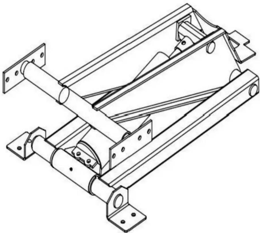
natural_image
Technical line drawing of a mechanical frame assembly (no text or symbols)NEED HELP? CONTACT US!
Have product questions? Need technical support? Please feel free to contact us: Technical Support and E-Warranty Certificate www.vevor.com/support
This is the original instruction, please read all manual instructions carefully before operating reserves a clear interpretation of our user manual. The appearance of the product shall be product you received. Please forgive us that we won't inform you again if there are any software updates on our product.

Warning-To reduce the risk of injury, user must read instructions manual carefully.
This manual covers proper hoist installation, hydraulic connections, wiring and service of the Dump Trailer Hydraulic hoists.
NOTICE: READ THIS ENTIRE MANUAL BEFORE ATTEMPTING TO INSTALL ANY COMPONENT CONTAINED IN THE HOIST KIT.
This manual should be kept at all times with the trailer, jack, hoist or other equipment or which this Dump Trailer Hydraulic product is used or installed.
NOTE: Installation of Dump Trailer Hydraulic products on your truck or trailer or other equipr void or affect the truck or trailer.
natural_image
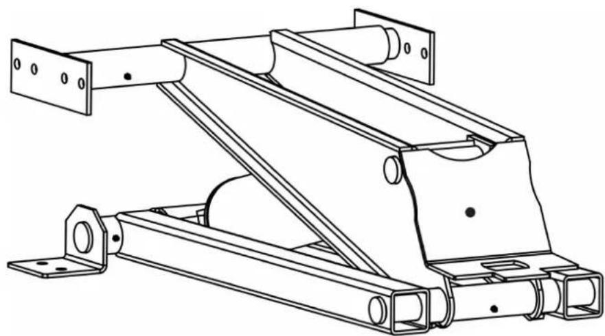
Technical line drawing of a mechanical support structure with mounting brackets and structural beams (no text or symbols)→ LIMITS OF LIABILITY
Should the product fail, the sole recourse is repair or replacement, as described in the prec paragraphs. Dump Trailer Hydraulic is not liable to any party for direct, indirect or consequent damage(s) resulting from failure of the product. Under no circumstances will Dump Trailer Hy be responsible for lost profit, lost savings, damage to other equipment, rental or replacement other incidental or consequential damages arising from use or inability to use the product. D any, recoverable against Dump Trailer Hydraulic shall under no circumstances exceed the current price of the product excluding tax, shipping and handling charges.
By using the product, user accepts all terms stated herein. Dump Trailer Hydraulic reset the right to make improvements to any model or product without notice.
SAFETY FIRST
IT IS YOUR DUTY AND RESPONSIBILITY TO COMPLETELY READ THROUGH AND UNDERSTAND THIS MANUAL AND ALL OTHER MATERIALS PROVIDED WITH Dump Trail Hydraulic PRODUCT(S)(INCLUDING MATERIALS PROVIDED BY THIRD PARTY
MANUFACTURERS) BEFORE ATTEMPTING ANY INSTALLATION OR OPERATION OF Dump Trailer Hydraulic OR THIRD PARTY PRODUCT(S) SUPPLIED BY PREMIUM SUPPLY. IF A TIME YOU HAVE QUESTIONS ABOUT THE INSTALLATION OR OPERATION OF Dump Truck Hydraulic OR Dump Trailer Hydraulic SUPPLIED PRODUCT(S) OR ABOUT THE CONTENTS
THIS MANUAL, CONTACT Dump Trailer Hydraulic BEFORE PROCEEDING WITH THE CONTEMPLATED.
INSTALLATION OR OPERATION. Dump Trailer Hydraulic IS NOT RESPONSIBLE FOR PROPERTY DAMAGE OR PERSONAL INJURY OR DEATH THAT MAY OCCUR FOR YOUR FAILURE TO COMPLY WITH THESE REQUIREMENTS.
This symbol is used to call attention to instructions concerning personal safety. Be sure observe and follow these instructions. Take time to read thoroughly and to be careful!
A brief description of signal words that are used in this manual follows:
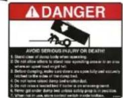
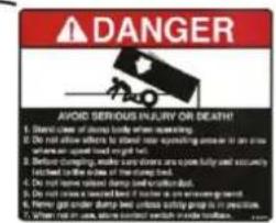
⚠️ ADANGER Indicates an imminently hazardous situation which, if not avoided, WILL result property damage, death or serious injury.
WARNING Indicates a potentially hazardous situation which, if not avoided, COULD result property damage, death or serious injury and includes hazards that are exposed when guards are removed.
CAUTION Indicates a potentially hazardous situation which, if not avoided, MAY result property damage or minor or moderate person injury including death. It is also used to alert unsafe practices.
SAFETY SIGN LOCATIONS
Installing or operating this equipment without first understanding proper installation and operatic procedures could lead to serious property damage, personal injury or even death. Always rea fully understand all installation and operation manuals before installing or operating this equipr Contact Dump Trailer Hydraulic with any questions. Read all safety signs on the trailer and included with or stated in this manual. Keep these signs clean and replace any lost, damag destroyed signs.
SAFETY PRECAUTIONS
Installing or operating this hoist without first understanding proper installation and operation procedures could lead to serious injury or death. Always read and fully understand all installa operation manuals before installing or operating this equipment. Contact Dump Trailer Hydraulic any questions.
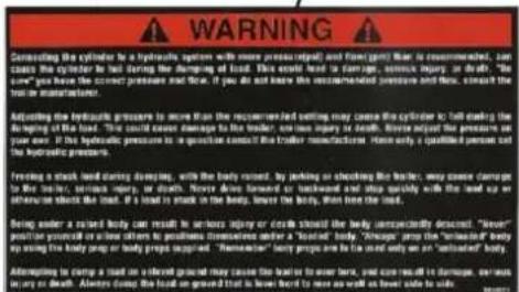
WARNING
Overloading a trailer could cause vehicle or trailer component damage resulting i
injury or death. NEVER exceed the gross vehicle weight (GVW) or gross axle weight (GAW) the trailer or your vehicle.
WARNING
Damage to brake lines during manufacturing and installation of the hoist, as well
installing any hardware (bolts, nuts, brackets) in a way that they may rub and damage the system, could lead to brake failure. This can cause an accident that could cause injury or ALWAYS take adequate steps to prevent brake system damage during installation of the hoist take precaution to ensure that installed equipment does not interfere with brake system.
WARNING
Malfunctioning equipment could cause property damage, injury or death. ALWAYS
have faulty equipment repaired before continuing use. Consult the trailer manufacturer if requii
WARNING
Welding, oxy-fuel cutting, or grinding could cause fuel to ignite. This could lead
or death. ALWAYS take adequate steps to avoid the ignition of fuel from fuel tanks when v oxy-fuel cutting, and/or grinding during installation. Heat from the vehicles exhaust system could cause hydraulic component failure. This could lead to a fire that can lead to injury or death install equipment in locations where the exhaust system heat will not damage any component to operation.
PARAMETER LIST
| Model | ER-006(8T) | ER-006(10T) |
| Load Capacity | 8T ( 17600lbs ) | 10T ( 22000lbs ) |
| Trailer tilt body length | 10-14ft | 12-16ft |
| Current of Battery Cable | ≥200A | ≥200A |
| Action | Double | Double |
| Voltage | DC 12V | DC 12V |
| Reservoir Capacity | 8 Quart | 10 Quart |
| Power | 1.6 KW | 1.6 KW |
| Rotating Speed | 2600 RPM | 2600 RPM |
| Pressure | 16~20 MPa | 16~20 MPa |
| Traffic | 2.1 mL/r | 2.1 mL/r |
| Tank Material | Plastic | Plastic |
| Color | Black | Black |
PART LIST
When unpacking this product, ensure the parts listed below are included and carefully inspected damage that may have occurred during transit. Do not attempt to assemble or use the product part is missing or damaged.
| PART NAME | PICTURE | QTY | PART NAME | PICTURE | QTY | |
| Hoist Assembly(include support plate) | 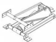 | 1 | Hydraulic Fittings | 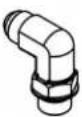 | 2 | |
| Hydraulic Power Unit | 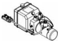 | 1 | Battery Cables | 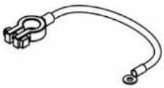 | 1 | |
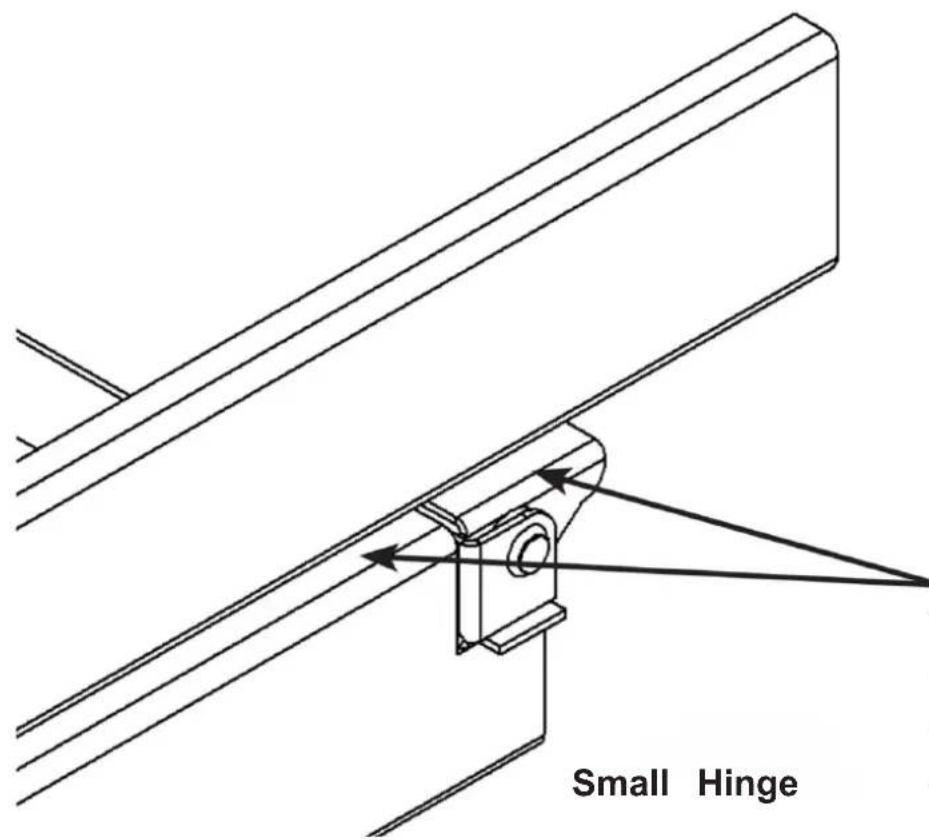
| Safety Arm | 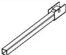 | 1 | Hinge (Styles Vary) | 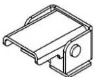 | 2 | |
| Safety Arm Cup | 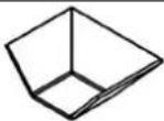 | 1 | Safety Arm Storage Bracket | 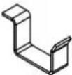 | 1 | |
| Rubber Battery Strap | 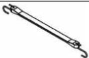 | 1 | Hydraulic Hose Between HPU and Cylinder | 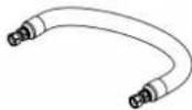 | 2 | |
| Hydraulic Fittings |  | 2 | Locking Collars | 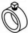 | 2 |
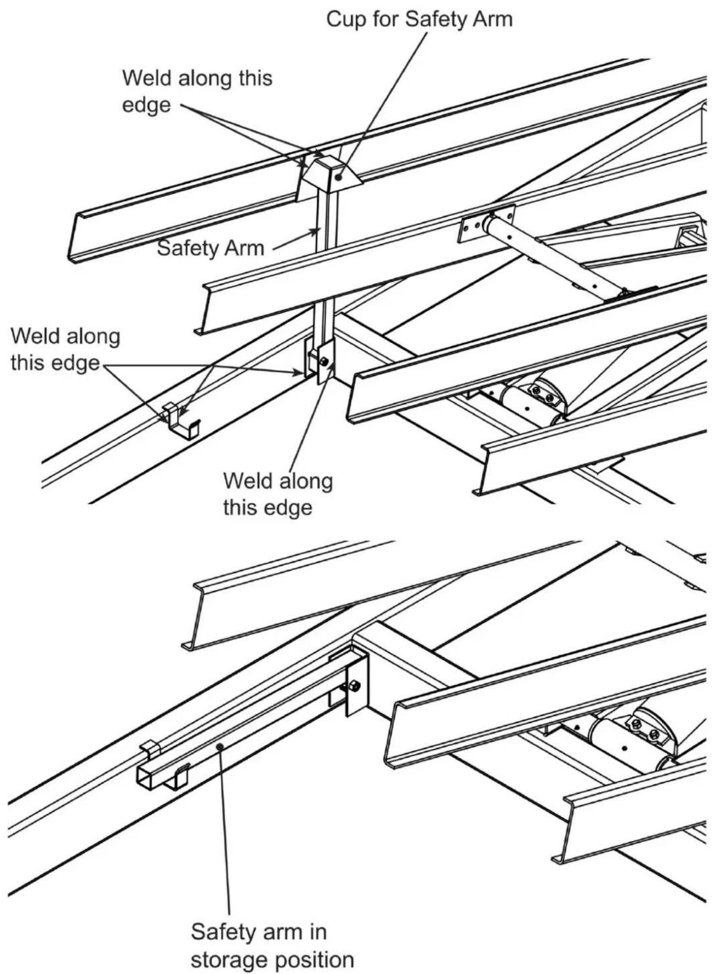
SAFETY ARM INSTALLATION AND USE

Always support an unloaded body with the safety arm. The safety arm is mean
support the weight of an unloaded body only.

Being under a raised body could result in serious injury or death should the bc
unexpectedly descend. Never position yourself or allow others to position themselves under a body. Always support an unloaded body with the supplied safety arm. NEVER use the safety loaded body.
Safety Arm Use:
- Raise trailer body to sufficient height and shut off hydraulic power to hoist.
- Grasp safety arm and rotate into the up/vertical position.
- Once vertical position is accomplished, push arm down into the support bracket at base (
- SLOWLY lower the hoist and body until the cup contacts the vertical facing arm.
- Reverse the above procedure to place arm back in its hanger for transport (be sure to full down position upon placing arm back in hanger).
Maximum Unloaded Tilt Body Weight in Pounds Using One Safety Arm
| Trailer tilt body length in feet | ||||||||
| Distance between hinge and safety arm | in inch | 8 | 10 | 12 | 14 | 16 | 18 | 20 |
| 50 | 3854 | 3083 | 2569 | 2202 | 1927 | 1713 | 1542 | |
| 60 | 4625 | 3700 | 3083 | 2643 | 2313 | 2056 | 1850 | |
| 70 | 5396 | 4317 | 3597 | 3083 | 2698 | 2398 | 2158 | |
| 80 | 6167 | 4933 | 4111 | 3524 | 3083 | 2741 | 2467 | |
| 90 | 6938 | 5550 | 4625 | 3964 | 3469 | 3083 | 2775 | |
| 100 | 6167 | 5139 | 4405 | 3854 | 3426 | 3083 | ||
| 110 | 6783 | 5653 | 4845 | 4240 | 3769 | 3392 | ||
| 120 | 7400 | 6167 | 5286 | 4625 | 4111 | 3700 | ||
| 130 | 6681 | 5726 | 5010 | 4454 | 4008 | |||
| 140 | 7194 | 6167 | 5396 | 4796 | 4317 | |||
| 150 | 6607 | 5781 | 5139 | 4625 | ||||
| 160 | 7048 | 6167 | 5481 | 4933 | ||||
| 170 | 6552 | 5824 | 5242 | |||||
| 180 | 6938 | 6167 | 5550 | |||||
| 190 | 7323 | 6509 | 5858 | |||||
| 200 | 6852 | 6167 | ||||||
| 210 | 7194 | 6475 | ||||||
| 220 | 6783 | |||||||
| 230 | 7092 | |||||||
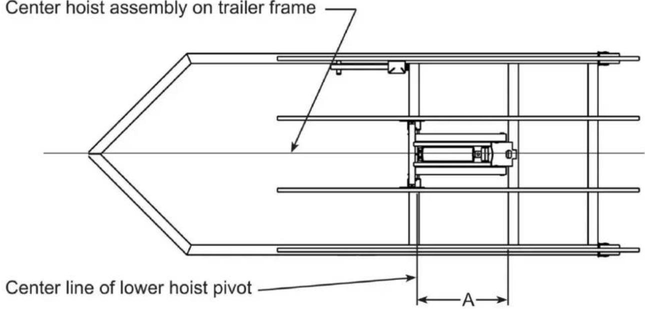
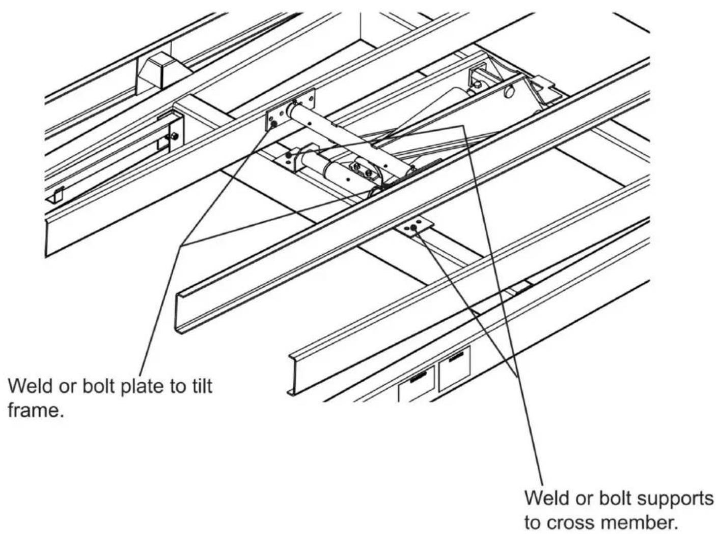
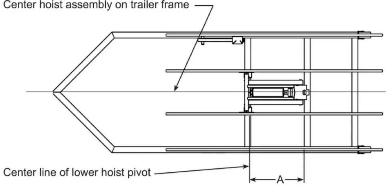
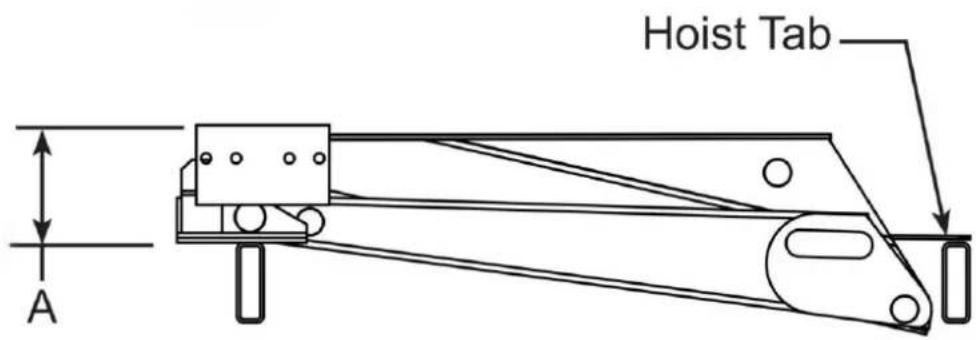
HINGE INSTALLATION
Mount hinge so pad of hinge is level with trailer frame.
Center hinge on support and weld hinge to supp at all contact surfaces.
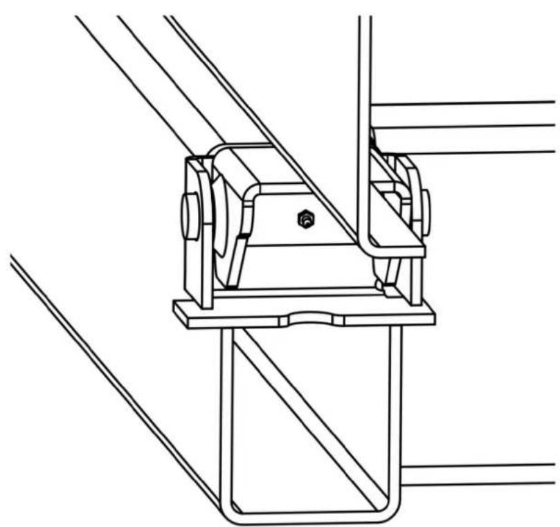
natural_image
Technical line drawing of a mechanical clamp or bracket assembly (no text or symbols)| Hoist Model | Dimension A |
| ER-006(8T) | 38” |
| ER-006(10T) | 46” |
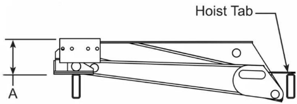
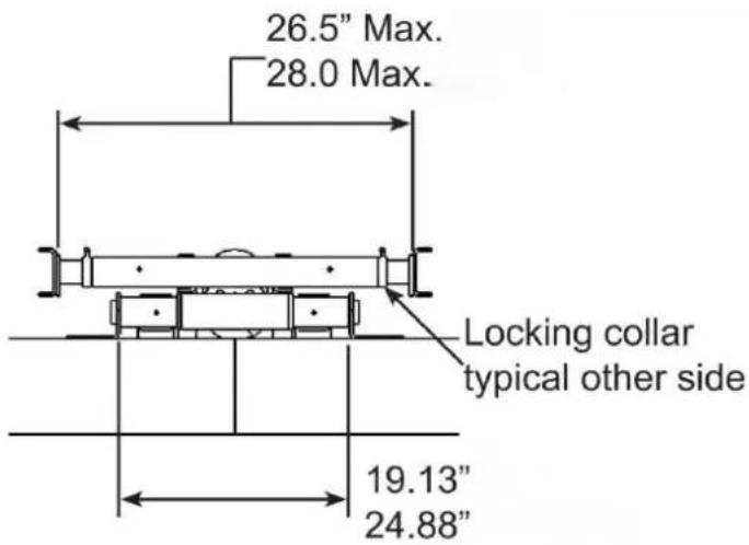
HOIST MOUNTING DIMENSIONS
| Hoist Model | A |
| ER-006(8T) | 7” |
| ER-006(10T) | 7” |

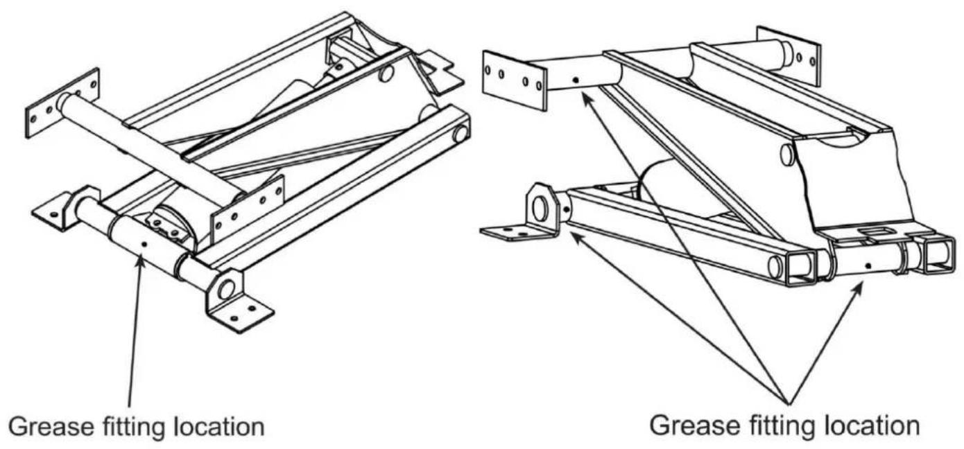
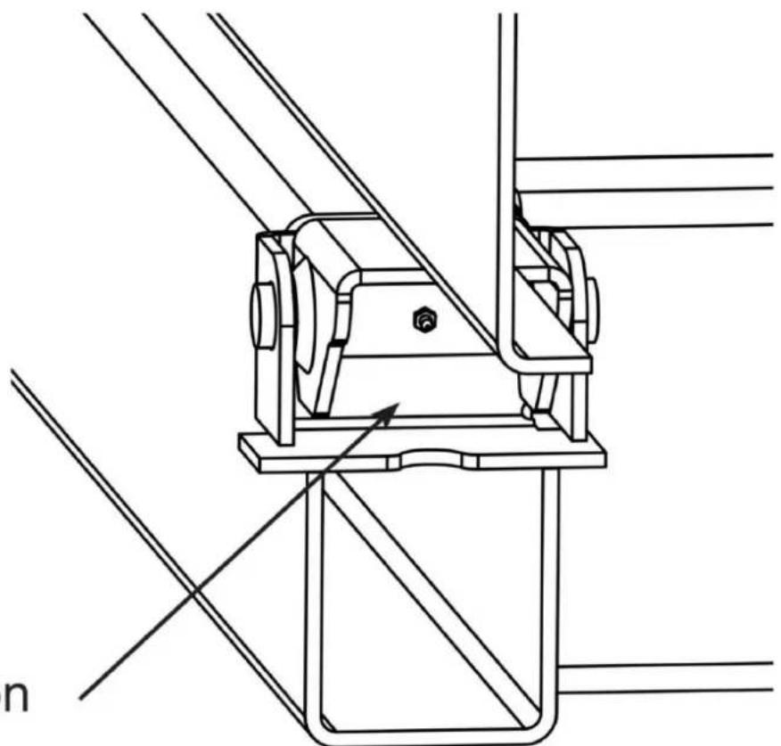
HOIST AND HINGE GREASE POINTS

Grease fitting location

natural_image
Technical line drawing of a mechanical assembly with diagonal braces and a central bracket (no text or symbols)Lubricate the joint with EP3 grease every 6 months
SINGLE AND DUAL ACTING HYD. POWER UNIT INSTALLATION
If included with the kit, mount HPU (hydraulic power unit) in a weather tight enclosure on the. See additional instructions supplied with the HPU for mounting, electrical, wireless remote and hydraulic fluid requirements.

Hydraulic components that are not provided by Dump Trailer Hydraulic and are in the hydraulic circuit that are incompatible with Dump Trailer Hydraulic components may cause damage to, or failure or malfunction of, the direct push cylinder or other components of the Trailer Hydraulic product(s). Such damage, failure or malfunction may cause property damage, personal injury or even death, It is the purchaser's responsibility to verify the compatibility of components not provided by Dump Trailer Hydraulic.

Connecting the jack to a hydraulic system with more pressure (PSI) or flow (G than is recommended by Dump Trailer Hydraulic could cause the jack to fail during operation failure could cause property damage, personal injury, or even death. Ensure that you have p that does not exceed tolerances and limits stated for your Dump Trailer Hydraulic product(s)/component(s), and that there is no restriction or issue concerning flow before opera Consult Dump Trailer Hydraulic if you are unsure about the limits, capacities and/or tolerances of your hydraulic system.

Adjusting the hydraulic pressure to exceed the recommended limits or setting co cause the jack to fail during operation. Such failure could cause property damage, personal death. Pressure should ONLY be adjusted by a trained and qualified technician or mechanic, should never exceed stated limits or settings of components used.
Hydraulic System Pre-Operation
The hydraulic system supplied by Dump Trailer Hydraulic consists of components (pump, valve reservoir, hoses, cylinder, etc.) that are designed to be compatible with each other.
All Dump Trailer Hydraulic's liability will be voided if determined by Dump Trailer Hydraulic the substituted hydraulic components (i.e., hydraulic components not provided by Dump Trailer Hydraulic as part of the kit) were used and such components were incompatible with components of the provided by Dump Trailer Hydraulic. Hydraulic parameters are shown below. These are listed general guide to ensure proper compatibility (when using other hydraulic components). If you any questions about component compatibility, please contact Dump Trailer Hydraulic before installation, use or maintenance.
Maximum Working Pressure---3200 PSI
Hydraulic Port Type--SAE#6
DUAL ACTING HPU CONNECTIONS
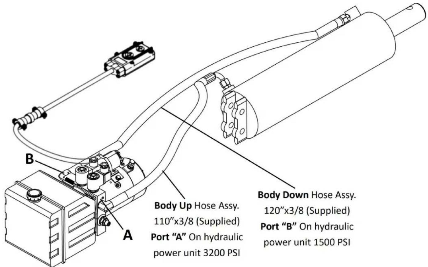
| Maximum Hydraulic Flow Rate | 2 GPM | Port |
| Maximum Pressure For “Raising” Portion of Cycl | 3200 PSI | A |
| Maximum Pressure For “Lowering” portion of Cy | 1500 PSI | B |
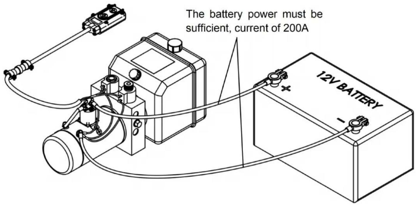
TYPICAL BATTERY HOOKUP

Shorting of the electrical system brought about by installation, servicing or repair
battery related connection and electrical components can cause sparks, ignition of combustible material and/or fire which in turn can lead to property damage, personal injury or death. AL' disconnect the battery prior to installing, servicing, or repairing power unit.
Mount battery in a weather tight enclosure on the trailer.
● The battery power must be sufficient, current of 200A and voltage to match the machine.
- This vehicle hydraulic pump is an S3 working system, not continuous operation, 30 second start, 270 seconds to stop, the maximum working time of 180 seconds, intermittent 360 second continuous working time is too long, will cause motor short circuit or damage.
- When the hydraulic power unit produced by our Company leaves the factory, the system has been set. If changes are needed, users can adjust the system pressure by themselves
pressure regulator knob according to the actual situation, but it cannot exceed the nominal p (18 MPa) of the system.
- Check the connection of the motor and electromagnetic valve carefully, and it is strictly forbidden to make a virtual connection.
- The hydraulic power unit should use anti-wear hydraulic oil with a kinematic viscosity of 22-46mm2/s (50°C). ISO VG46 is recommended when the oil temperature is below 50°C, which VG68 is recommended when the oil temperature is above 50°C. The added oil should be filtered with a filtration accuracy of 30um. The oil volume should be 80% of the effective capacity oil tank. The oil temperature is usually between -10\~80°C, and low-temperature hydraulic oil can be used for extremely cold areas, such as ISO VG32. These measures can effectively prolong service life of the hydraulic system and hydraulic components, and improve the stability and quality of the hydraulic power unit.
- During the first installation and debugging, pay attention to keeping the oil level inside the oil tank, and after a working cycle, the oil tank should be filled, but it cannot be overfilled.
- The motor terminal box should be waterproof and moisture-proof. When connecting for the time, inching the motor to carefully check the direction of the motor. From the rear end of the rotation direction is counterclockwise. It is absolutely forbidden to reverse the rotation of and idle without oil.
- The hydraulic oil must be filtered when the oil tank is filled, with a filtering accuracy of no less than 25 m .
● The power unit cannot filter out impurities inside the hydraulic cylinder. Therefore, the inside of the hydraulic cylinder must be clean to avoid the failure of the valve. The tubing must also be
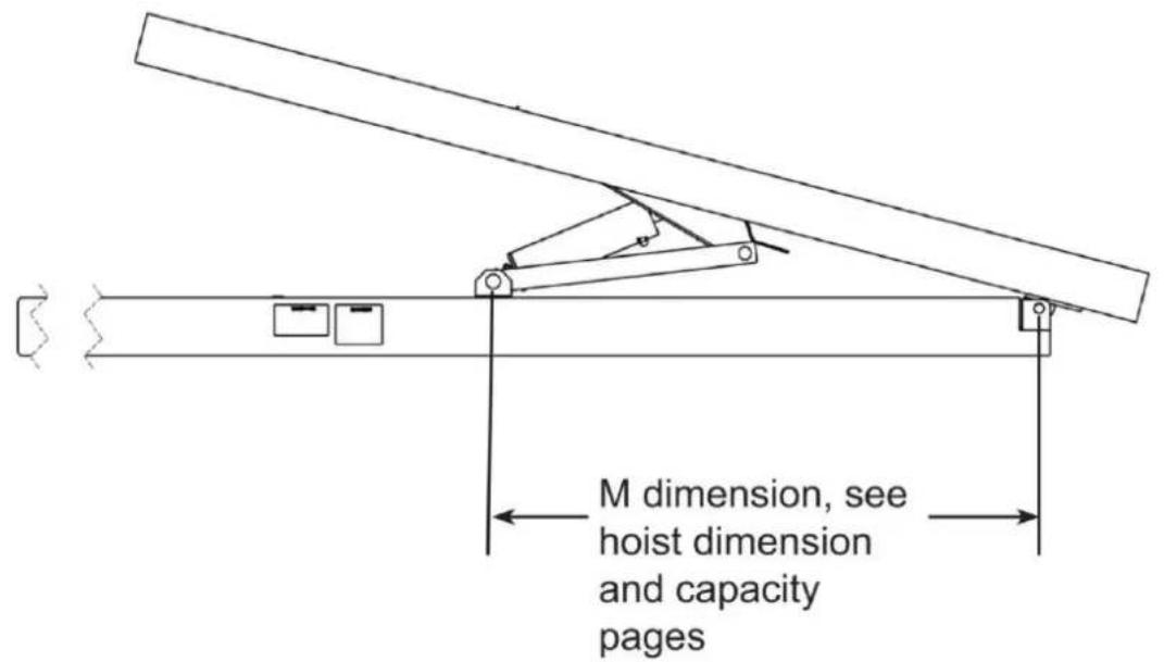
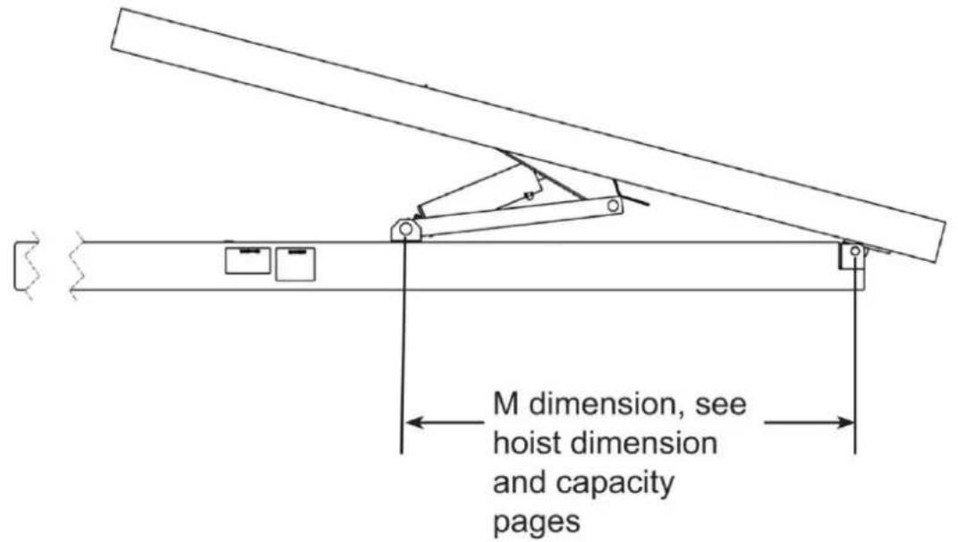
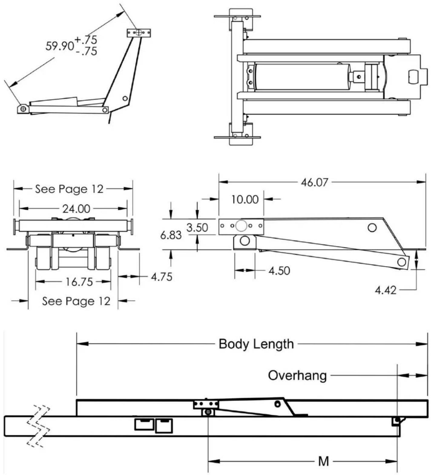
ER-006(8T) DUMP TRAILER HYDRAULIC HOIST KIT DIMENSIONS AND CAPACITY
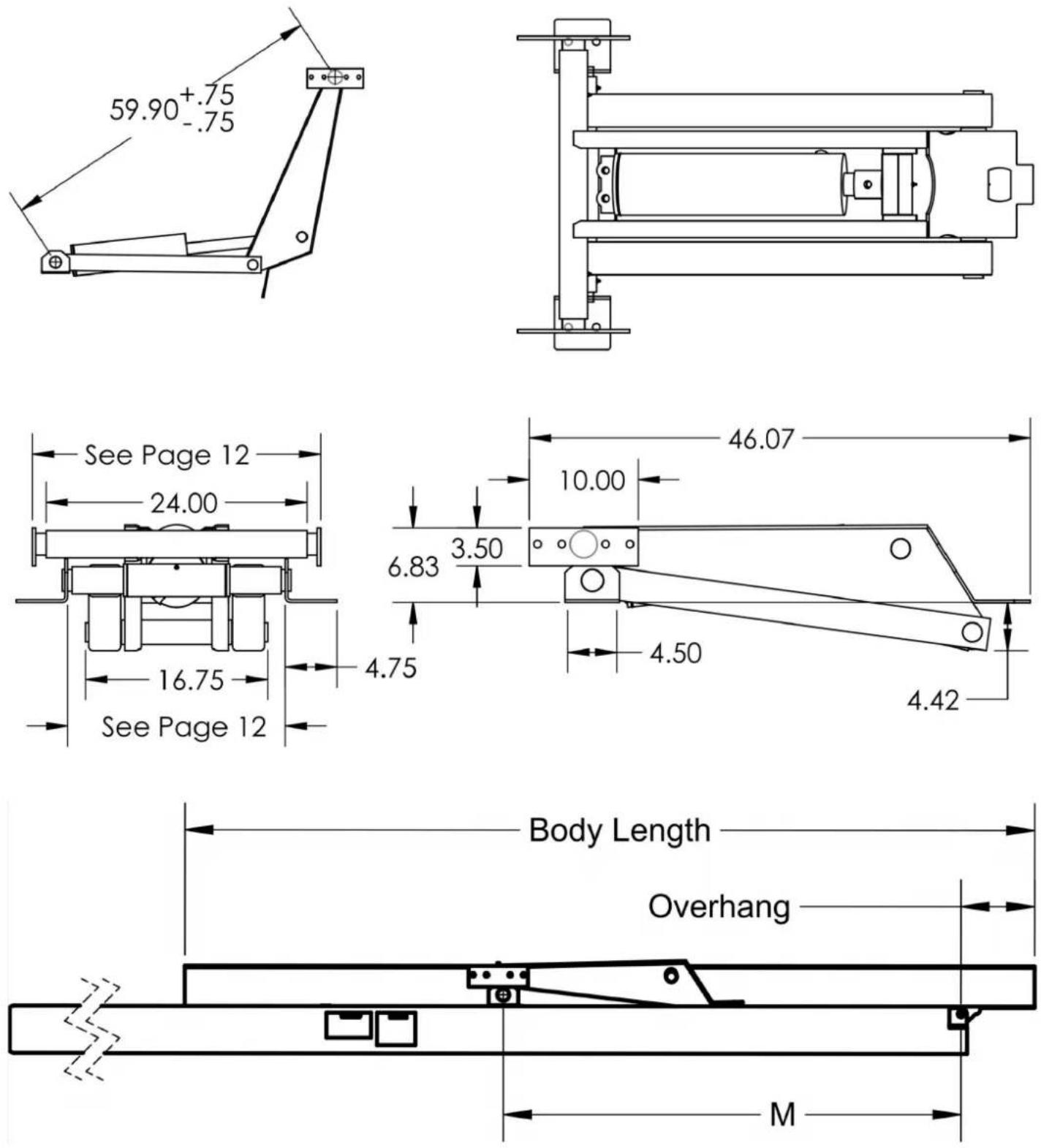
| Maximum Dump Angle ± | M |
| 45° | 73” |
| 50° | 66” |
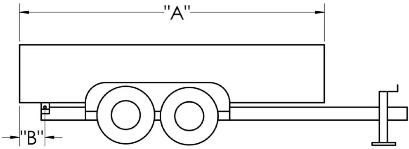
ER-006(8T)DUMP TRAILER HYDRAULIC HOIST KIT CONVERSION CLASS A
IMPORTANT: Because of variations in application, the data contained in these tables is provided as a general guide only.
| ER-006(8T)Dump Trailer Hydraulic Hoist Kit Capacity (Tons) | |||
| “A”Body(Feet) | “B”Overhang(Inches) | Dump Angle (Degrees) | |
| 45° | 50° | ||
| 10 | 12 | 9.7 | 8.8 |
| 10 | 18 | 11.1 | 10.0 |
| 10 | 24 | 12.9 | 11.7 |
| 12 | 12 | 7.7 | 7.0 |
| 12 | 18 | 8.6 | 7.8 |
| 12 | 24 | 9.7 | 8.8 |
| 14 | 12 | 6.5 | 5.8 |
| 14 | 18 | 7.0 | 6.4 |
| 14 | 24 | 7.8 | 7.0 |
Capacities are based on the following:
- Water level non-diminishing load.
- The vertical height between the rear hinge pivot and the floor is no less than 3 in
- The hydraulic relief pressure set at 3,200 psi.
ER-006(10T) DUMP TRAILER HYDRAULIC HOIST KIT DIMENSIONS AND CAPACITY
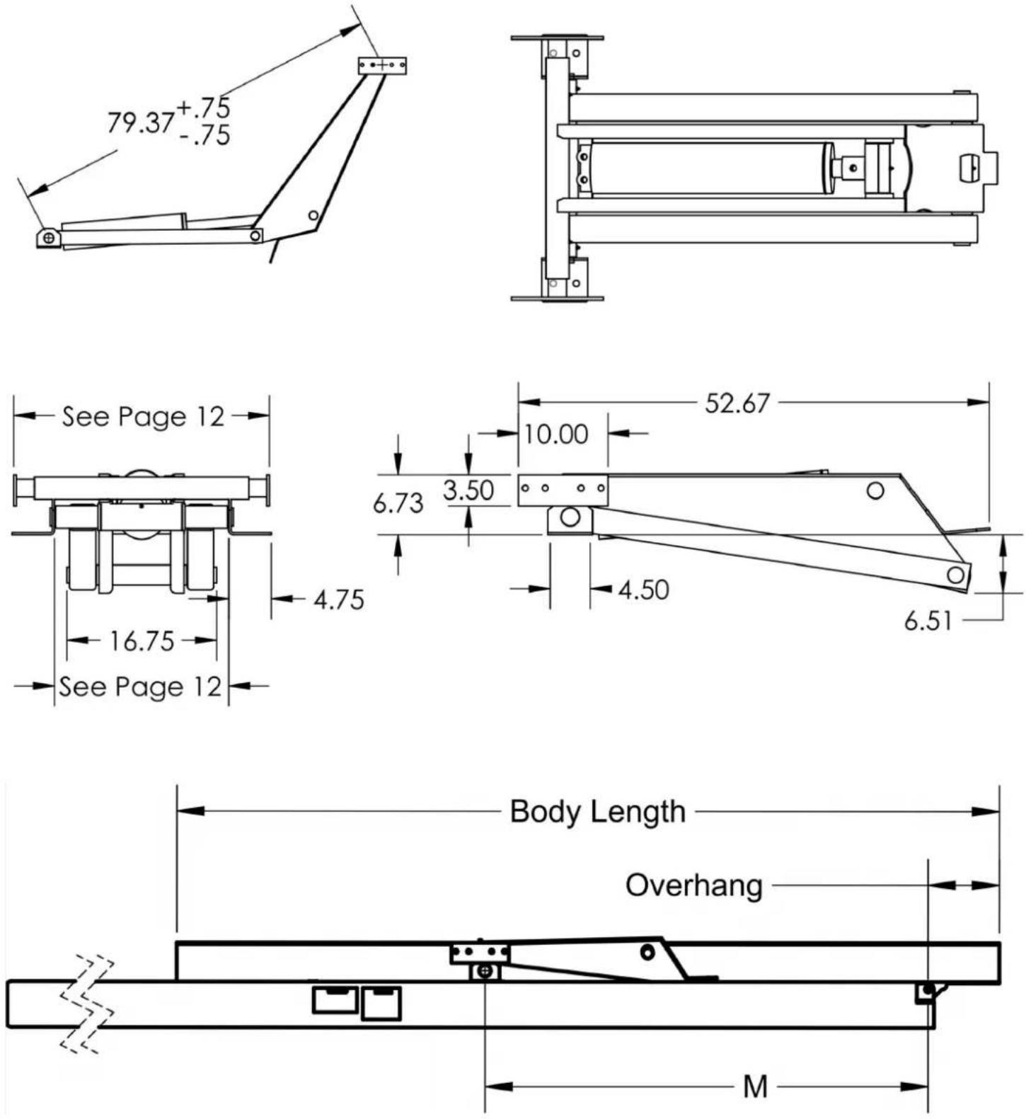
| Maximum Dump Angle ± | M |
| 45° | 97” |
| 50° | 88” |
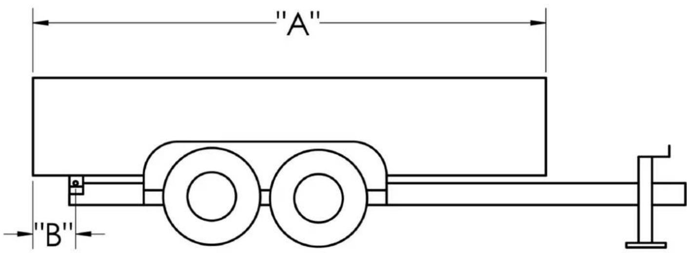
ER-006 (10T) DUMP TRAILER HYDRAULIC HOIST KIT CONVERSION CLASS A
IMPORTANT: Because of variations in application, the data contained in these tables is provided as a general guide only.
| ER-006(10T)Dump Trailer Hydraulic Hoist Kit Capacity (Tons) | |||
| “A” Body (Feet) | “B” Overhang (Inches) | Dump Angle (Degrees) | |
| 45° | 50° | ||
| 12 | 12 | 10.3 | 9.3 |
| 12 | 18 | 11.4 | 10.4 |
| 12 | 24 | 12.9 | 11.7 |
| 14 | 12 | 8.6 | 7.8 |
| 14 | 18 | 9.3 | 8.5 |
| 14 | 24 | 10.3 | 9.3 |
| 16 | 12 | 7.3 | 6.7 |
| 16 | 18 | 7.9 | 7.2 |
| 16 | 24 | 8.6 | 7.8 |
Capacities are based on the following:
- Water level non-diminishing load.
- The vertical height between the rear hinge pivot and the floor is no less than 3 in
- The hydraulic relief pressure set at 3,200 psi.
VEVOR®
TOUGH TOOLS, HALF PRICE
natural_image
Technical line drawing of a mechanical frame assembly (no text or symbols)BESOIN D'AIDE? CONTACTEZ-NOUS!
natural_image
Technical line drawing of a mechanical support structure with mounting brackets and structural beams (no text or symbols)→ LIMITES DE RESPONSABILITÉ
Machine Translated by Google
CE MANUEL, CONTACTEZ Dump Trailer Hydraulic AVANT DE PROCÉDER AUX TRAVAUX ENVISAGÉS.
INSTALLATION OU FONCTIONNEMENT. Dump Trailer Hydraulic N'EST PAS RESPONSABLE DES DOMMAGES MATÉRIELS OU DES BLESSURES CORPORELLES OU DE LA MORT POUVANT SURVENIR EN RAISON DE VOTRE NON-RESPECT DE CES EXIGENCES.

natural_image
Technical line drawing of a mechanical clamp or bracket assembly (no text or symbols)EMPLACEMENT DU PONT SUR LA REMORQUE
Center hoist assembly on trailer frame


| Dimension A_Mod | |
| ER-006(8T) | 38” |
| ER-006(10T) | 46” |
èle de |
DIMENSIONS DE MONTAGE DU PALAN
| Palans modèle A |
| ER-006(8T) 7" |
| ER-006(10T) 7" |


POINTS DE GRAISSAGE DU PALAN ET DE LA CHARNIÈRE


natural_image
Technical line drawing of a mechanical assembly with diagonal braces and a central bracket (no text or symbols)Grease fitting location
Machine Translated by Google
DIMENSIONS ET CAPACITÉ DU KIT DE LEVAGE HYDRAULIQUE POUR REMORQUE À BENNE BASCULANTE ER-006 (8T)

Machine Translated by Google
natural_image
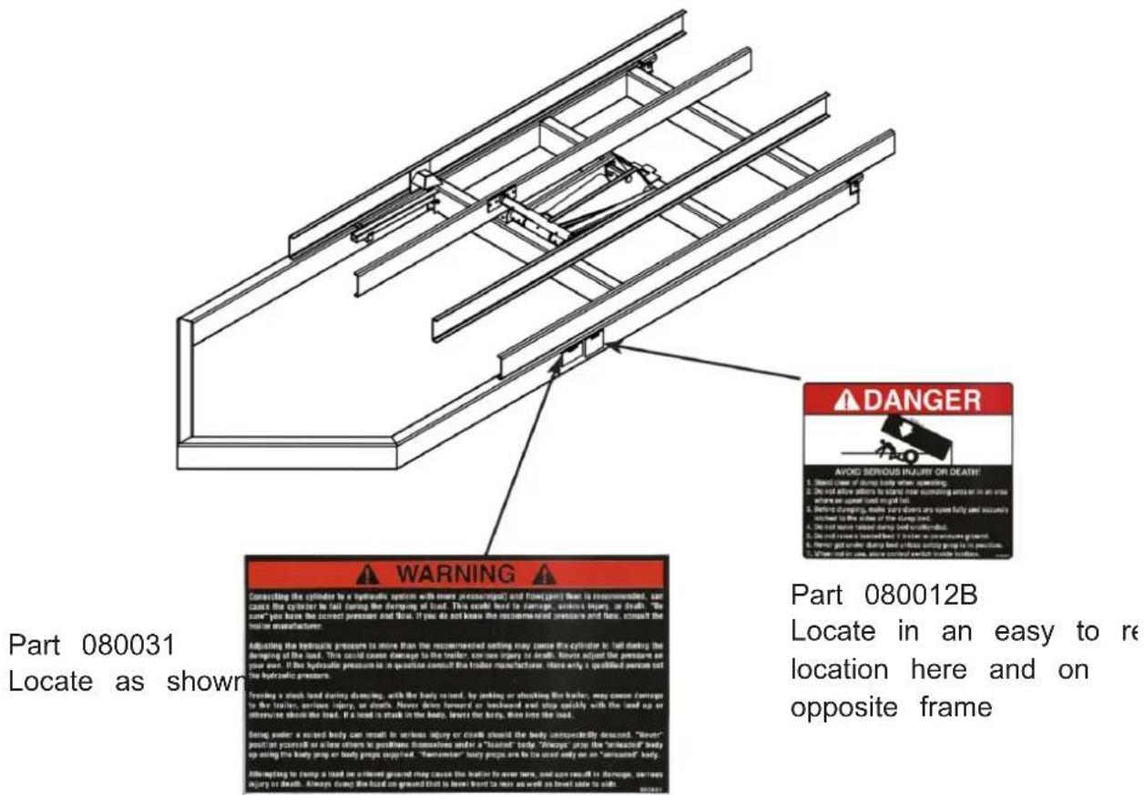
Technical line drawing of a mechanical frame assembly (no text or symbols)natural_image
Technical line drawing of a mechanical support structure with mounting brackets and structural beams (no text or symbols)Teil 080031
Teil 080012B
natural_image
Technical line drawing of a mechanical clamp or bracket assembly (no text or symbols)POSITION DES HEBEZEUGS AUF DEM ANHÄNGER

Center hoist assembly on trailer frame


| Abmessung AHebezeugmod | |
| ER-006(8T) | 38" |
| ER-006(10T) | 46" |

SCHMIERPUNKTE FÜR HEBE- UND SCHARNIERSYSTEME


natural_image
Technical line drawing of a mechanical assembly with diagonal braces and a central bracket (no text or symbols)Grease fitting location
Machine Translated by Google
natural_image
Technical line drawing of a mechanical frame assembly (no text or symbols)natural_image
Technical line drawing of a mechanical support structure with mounting brackets and structural beams (no text or symbols)ÿ LIMITI DI RESPONSABILITÀ
Parte 080031
Parte 080012B
natural_image
Technical line drawing of a mechanical clamp or bracket assembly (no text or symbols)
PUNTI DI INGRASSAGGIO DEL PARANCO E DELLA CERNIERA


natural_image
Technical line drawing of a mechanical assembly with diagonal braces and a central bracket (no text or symbols)Grease fitting location
Machine Translated by Google
ER-006(8T) KIT DI SOLLEVAMENTO IDRAULICO PER RIMORCHIO CON CASSONE RIBALTABILE DIMENSIONI E CAPACITÀ

natural_image
Technical line drawing of a mechanical frame assembly (no text or symbols)natural_image
Technical line drawing of a mechanical support structure with mounting brackets and structural beams (no text or symbols)natural_image
Technical line drawing of a mechanical clamp or bracket assembly (no text or symbols)Center hoist assembly on trailer frame


PUNTOS DE ENGRASE DE POLIPASTO Y BISAGRAS


natural_image
Technical line drawing of a mechanical assembly with diagonal braces and a central bracket (no text or symbols)Grease fitting location
Machine Translated by Google
natural_image
Technical line drawing of a mechanical frame assembly (no text or symbols)POTRZEBUJESZ POMOCY? SKONTAKTUJ SIĘ Z NAMI!
natural_image
Technical line drawing of a mechanical support structure with mounting brackets and structural beams (no text or symbols)OGRANICZENIA ODPOWIEDZIALNOŚCI
Machine Translated by Google
W TEJ INSTRUKCJI SKONTAKTUJ SIĘ Z Dump Trailer Hydraulic PRZED PODJECIEM PLANOWANYCH DZIAŁAŃ.
INSTALACJA LUB EKSPLOATACJA. Dump Trailer Hydraulic NIE PONOSI ODPOWIEDZIALNOŚCI ZA USZKODZENIA MIENIA LUB OBRAŻENIA CIAŁA LUB ŚMIERĆ, KTÓRE MOGA WYSTĄPIĆ Z POWODU NIEPRZESTRZEGANIA TYCH WYMOGÓW.

Część 080031
Część 080012B
natural_image
Technical line drawing of a mechanical clamp or bracket assembly (no text or symbols)LOKALIZACJA WCIĄGARKI NA PRZYCZEPIE

Center hoist assembly on trailer frame

| Wymiar AModel podnośnika | |
| ER-006(8T) | 38" |
| ER-006(10T) | 46" |
WYMIARY MONTAŻOWE WCIĄGARKI
| Wciągnik Model A |
| ER-006(8T) 7" |
| ER-006(10T) 7" |

PUNKTY SMAROWANIA WCIĄGNIKA I ZAWIASU

natural_image
Technical line drawing of a mechanical assembly with diagonal braces and a central bracket (no text or symbols)Grease fitting location
Machine Translated by Google
ER-006(8T) WYWROTKA HYDRAULICZNA ZESTAW PODNOŚNIKÓW WYMIARY I ŁAdowność

Machine Translated by Google
natural_image
Technical line drawing of a mechanical assembly with no visible text or symbolsHULP NODIG? NEEM CONTACT MET ONS OP!
natural_image
Technical line drawing of a mechanical support structure with mounting brackets and structural beams (no text or symbols)ÿ AANSPRAKELIJKHEIDSBEPERKINGEN
VEILIGHEIDSMAATREGELEN
natural_image
Technical line drawing of a mechanical clamp or bracket assembly (no text or symbols)HIJSLOCATIE OP AANHANGWAGEN
Center hoist assembly on trailer frame

| Dimensie AHijsmodel | |
| ER-006(8T) | 38” |
| ER-006(10T) | 46” |
AFMETINGEN VAN DE HIJSMONTAGE
| Takel Model | A |
| ER-006(8T) | 7” |
| ER-006(10T) | 7” |


SMEERPUNTEN VOOR HIJS- EN SCHARNIEREN

Grease fitting location
natural_image
Technical line drawing of a mechanical assembly with diagonal braces and a central bracket (no text or symbols)Machine Translated by Google
ER-006(8T) DUMP TRAILER HYDRAULISCHE HIJSKIT AFMETINGEN EN CAPACITEIT

| Maximale storthoek ± 2° | M |
| 45° | 73” |
| 50° 66” |
ER-006(8T)DUMP TRAILER HYDRAULISCHE HIJSKIT CONVERSIE KLASSE A
natural_image
Technical line drawing of a mechanical frame assembly (no text or symbols)BEHÖVER HJÄLP? KONTAKTA OSS!
natural_image
Technical line drawing of a mechanical support structure with mounting brackets and mounting holes (no text or symbols)ÿ ANSVARSBEGRÄNSNINGAR
Del 080031
Lokalisera som visas
Del 080012B
natural_image
Technical line drawing of a mechanical clamp or bracket assembly (no text or symbols)LYFTPLACERING PÅ TRAILER

Center hoist assembly on trailer frame

| Dimension AHissmoc | |
| ER-006(8T) | 38" |
| ER-006(10T) | 46" |
LYFTMONTERINGSDIMENSIONER
| Lyft modell A | |
| ER-006(8T) 7" | |
| ER-006(10T) 7" |

SMÖTTPUNGAR FÖR LYFT OCH GJÄRN


natural_image
Technical line drawing of a mechanical clamp or bracket assembly (no text or symbols)Grease fitting location
Machine Translated by Google
ER-006(8T) DUMP TRAILER HYDRAULISK LYFTSET DIMENSIONER OCH KAPACITET
| Maximal tippvinkel ± 2° | M |
| 45° | 73" |
| 50° | 66" |


