
EM3500-24L - Solar inverter Vevor - Free user manual and instructions
Find the device manual for free EM3500-24L Vevor in PDF.
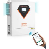


| Product Type | Hybrid Solar Inverter |
| Brand | Vevor |
| Model | EM3500-24L |
| Rated Power | 3500 VA / 3500 W |
| AC Input Voltage | 230 VAC (50/60 Hz) |
| AC Output Voltage | 230 VAC ±5% (Pure Sine Wave) |
| Max. PV Input Voltage | 500 VDC |
| MPPT PV Range | 60 VDC - 500 VDC |
| Nominal Battery Voltage | 24 VDC |
| Max. Charging Current (PV+AC) | 100 A |
| Dimensions (W x D x H) | 438 x 295 x 105 mm |
| Net Weight | 6.2 kg |
| Operating Temperature Range | -10 °C to 55 °C |
| Operating Humidity | 5% to 95% (non-condensing) |
| Display | Backlit LCD Screen |
| Communication | RS485, WiFi (antenna included) |
| Protections | Overload, Short Circuit, Overheating, Overvoltage, Battery Undervoltage, Reverse Polarity |
| Maintenance | Clean with a dry cloth; check connections periodically |
| Repairability | Contact a qualified professional; no user-serviceable parts |
| Warranty | Manufacturer warranty (see conditions on vevor.com/support) |
Frequently Asked Questions - EM3500-24L Vevor
User questions about EM3500-24L Vevor
0 question about this device. Answer the ones you know or ask your own.
Ask a new question about this device
Download the instructions for your Solar inverter in PDF format for free! Find your manual EM3500-24L - Vevor and take your electronic device back in hand. On this page are published all the documents necessary for the use of your device. EM3500-24L by Vevor.
USER MANUAL EM3500-24L Vevor
Technical Support and E-Warranty Certificate
www.vevor.com/support
HYBRID SOLAR INVERTER
USER MANUAL
MODEL: EM3500-24L / EM6200-48L
We continue to be committed to providing you with tools at competitive prices.
"Save Half", "Half Price", or any other similar expressions used by us only represent an estimate of savings you might benefit from buying certain tools with us compared to the top brands, and do not necessarily mean to cover all categories of tools offered by us.
We kindly remind you to verify carefully when placing an order with us if you are actually saving half in comparison with the top major brands.
VEVOR®
TOUGH TOOLS, HALF PRICE
HYBRID SOLAR INVERTER
MODEL: EM3500-24L / EM6200-48L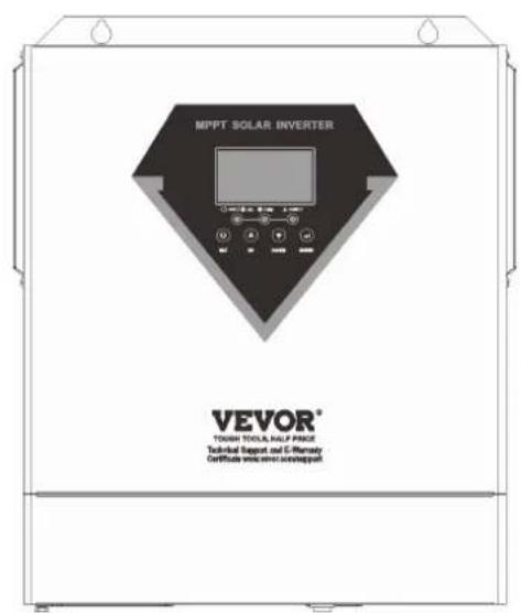
EM3500-24L
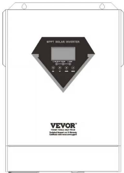
EM6200-48L
NEED HELP? CONTACT US!
Have product questions? Need technical support? Please feel free to contact us:
Technical Support and E-Warranty Certificate www.vevor.com/support
This is the original instruction. Please read all manual instructions carefully before operating. VEVOR reserves a clear interpretation of our user manual. The appearance of the product shall be subject to the product you received. Please forgive us that we won't inform you again if there are any technology or software updates on our product.
 | Warning-To reduce the risk of injury, user must read instructions manual carefully. |
 | This product is subject to the provision of European Directive 2012/19/EC. The symbol showing a wheelie bin crossed through indicates that the product requires separate refuse collection in the European Union. This applies to the product and all accessories marked with this symbol. Products marked as such may not be discarded with normal domestic waste, but must be taken to a collection point for recycling electrical and electronic devices |
WARNING: DANGER OF ELECTRICAL SHOCK
The product is used in combination with a permanent energy source (battery). Even if the equipment is switched off, a dangerous electrical voltage can occur at the input and/or output terminals. Always switch the AC power off and disconnect the battery before performing maintenance. The product contains no internal user-serviceable parts. Do not remove the front panel and do not put the product into operation unless all panels are fitted. All maintenance should be performed by qualified personnel.
Never use the product at sites where gas or dust explosions could occur. Refer to the specifications provided by the manufacturer of the battery to ensure that the battery is suitable for use with this product. The battery manufacturer's safety instructions should always be observed.
WARNING: do not lift heavy objects unassisted.
Installation
Read the installation instructions before commencing installation activities. This product is a safety class I device (supplied with a ground terminal for safety purposes). Its AC input and/or output terminals must be provided with uninterruptible grounding for safety purposes. An additional grounding point is located on the outside of the product. If it can be assumed that the grounding protection is damaged, the product should be taken out of
operation and prevented from accidentally being put into operation again; contact qualified maintenance personnel.
Ensure that the connection cables are provided with fuses and circuit breakers. Never replace a protective device by a component of a different type. Refer to the manual for the correct part.
Check before switching the device on whether the available voltage source conforms to the configuration settings of the product as described in the manual.
Ensure that the equipment is used under the correct operating conditions.
Never operate it in a wet or dusty environment.
Ensure that there is always sufficient free space around the product for ventilation, and that ventilation openings are not blocked.
Install the product in a heatproof environment. Ensure therefore that there are no chemicals, plastic parts, curtains or other textiles, etc. in the immediate vicinity of the equipment.
Transport and storage
On storage or transport of the product, ensure that the mains supply and battery leads are disconnected.
No liability can be accepted for damage in transit if the equipment is not transported in its original packaging.
Store the product in a dry environment; the storage temperature should range from -10°C to 50°C.
Refer to the battery manufacturer's manual for information on transport, storage, charging, recharging and disposal of the battery.
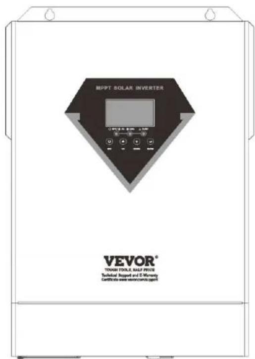
PRODUCT OVERVIEW
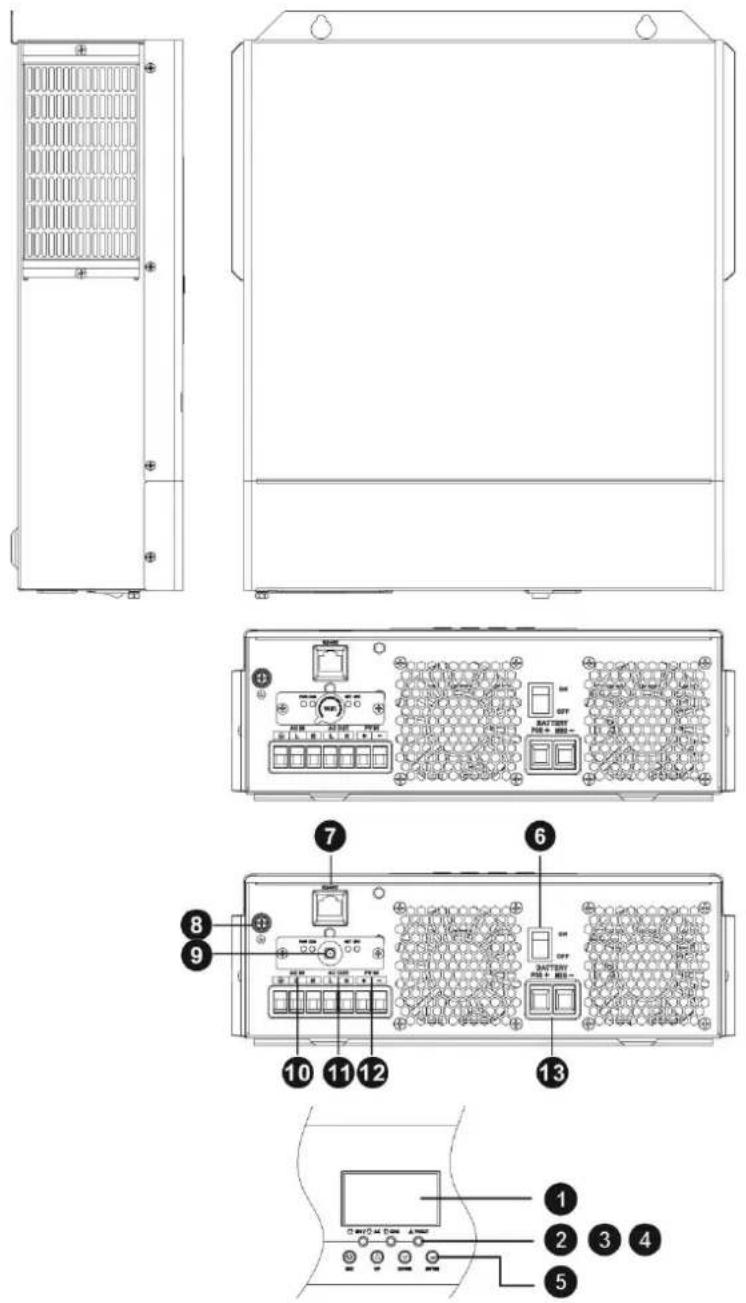
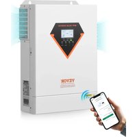
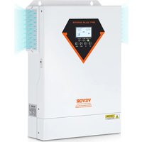
- LCD display
- Status indicator
- Charging indicator
- Fault indicator
- Function buttons
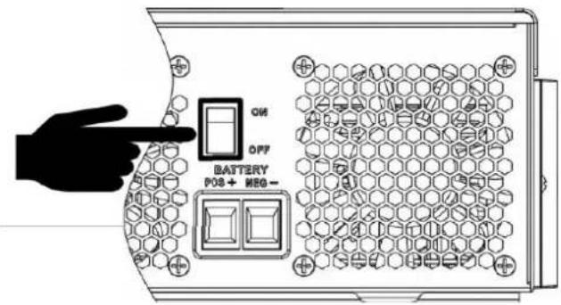
- Power on/off switch
- RS485 communication port
- Grounding
- WiFi antenna port
- AC input
- AC output
- PV input
- Battery input
INSTALLATION
Unpacking and Inspection
Before installation, please inspect the unit. Be sure that nothing inside the package is damaged. You should have received the following items inside of package:
- The unit x 1
- User manual x 1
- WiFi antenna x 1
Preparation
Before connecting all wirings, please take off bottom cover by removing two screws as shown below.
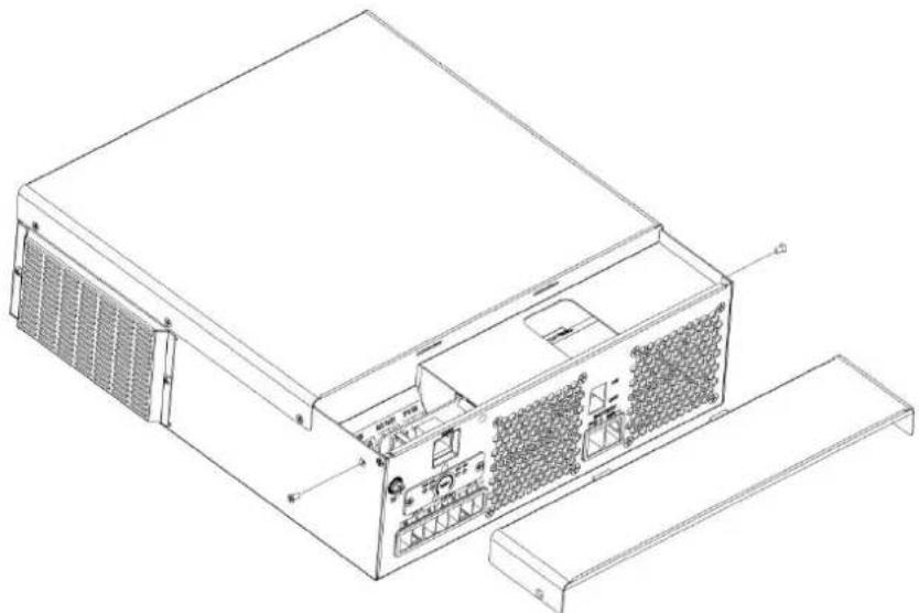
Mounting the Unit
Consider the following points before selecting where to install:
- Do not mount the inverter on flammable construction materials.
- Mount on a solid surface.
- Install this inverter at eye level in order to allow the LCD display to be read at all times.
- The ambient temperature should be between 0°C and 55°C to ensure optimal operation.
- The recommended installation position is to be adhered to the wall vertically.
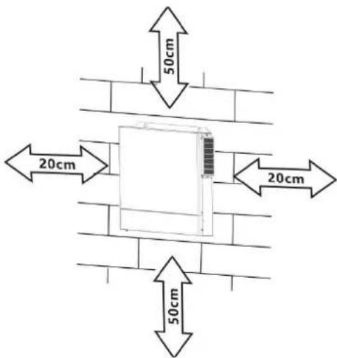
- Be sure to keep other objects and surfaces as shown in the right diagram to guarantee sufficient heat dissipation and to have enough space for removing wires.

SUITABLE FOR MOUNTING ON CONCRETE OR OTHER NON-COMBUSTIBLE SURFACE ONLY.
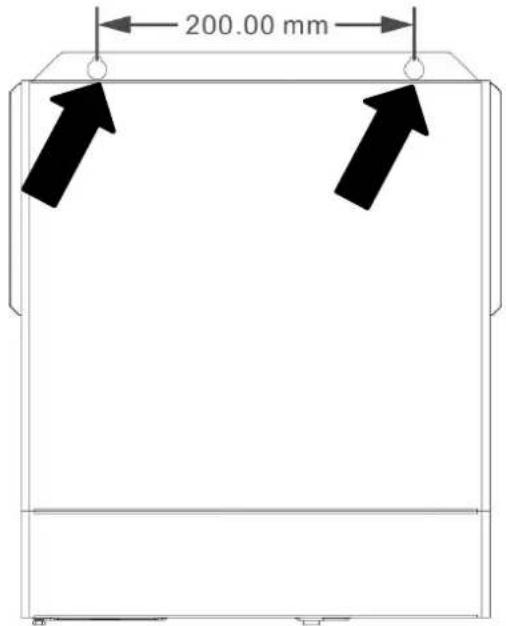
Install the unit by screwing three screws. It's recommended to use M4 or M5 screws.
Battery Connection
CAUTION: For safety operation and regulation compliance, it's requested to install a separate DC over-current protector or disconnect device between battery and inverter. It may not be requested to have a disconnect device in some applications, however, it's still requested to have over-current protection installed. Please refer to typical amperage in below table as required fuse or breaker size.
Stripping Length:
WARNING! All wiring must be performed by a qualified personnel.
WARNING! It's very important for system safety and efficient operation to use appropriate cable for battery connection. To reduce risk of injury, please use the proper recommended cable, stripping length (L2) and tinning length (L1) as below.
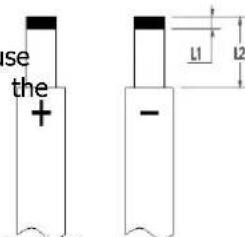
Recommended battery cable, stripping length (L2) and tinning length (L1):
| Model | Maximum Amperage | Battery capacity | Wire Size | Cable mm2 | L1 (mm) | L 2 (mm) | Torque Value |
| 1500W-24 70A | 100AH 6AWG | 13.3 3 | 18 2~3 Nm | ||||
| 2500W-24 | 100A | 100AH | 4AWG | 21.15 | 3 | 18 | 2~3 Nm |
| Other Models | 137A | 100AH | 2AWG | 38 | 3 | 18 | 2~3 Nm |
Please follow below steps to implement battery connection:
- Remove insulation sleeve 18 mm for positive and negative cables based on recommended stripping length.
- Connect all battery packs as units requires. It's suggested to use recommended battery capacity.
- Insert battery cable flatly into battery connector of inverter and make sure the bolts are tightened with torque of 2-3 Nm. Make sure polarity at both the battery and the inverter/charge is correctly connected and battery cables are tightly screwed to the battery connector.
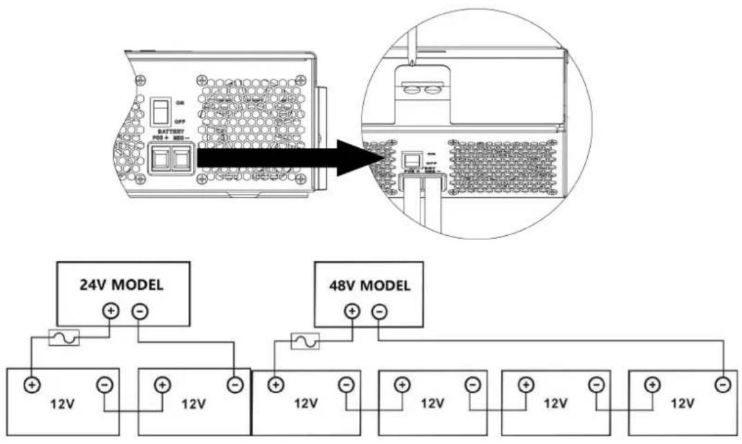
| WARNING: Shock HazardInstallation must be performed with care due to high battery voltage in series. |
| CAUTION!! Do not place anything between the flat part of the inverter terminal Otherwise, overheating may occur.CAUTION!! Do not apply anti-oxidant substance on the terminals before terminals are connected tightly.CAUTION!! Before making the final DC connection or closing DC breaker/disconnector, be sure positive (+) must be connected to positive (+) and negative (-) must be connected to negative (-). |
AC Input/Output Connection
CAUTION!! Before connecting to AC input power source, please install a separate AC breaker between inverter and AC input power source. This will ensure the inverter can be securely disconnected during maintenance and fully protected from over current of AC input. The recommended spec of AC breaker is 50A. CAUTION!! There are two terminal blocks with "IN" and "OUT" markings. Please do NOT mis-connect input and output connectors.
WARNING! All wiring must be performed by a qualified personnel.
WARNING! It's very important for system safety and efficient operation to use appropriate cable for AC input connection. To reduce risk of injury, please use the proper recommended cable size as below.
Suggested cable requirement for AC wires
| Model Gauge Torque Value | ||
| 1.5KVA 12AWG 1.4~ 1.6Nm | ||
| 2.5KVA/3.5KVA 10AWG 1.4~ 1.6Nm | ||
| 5.5KVA/6.2KVA | 8 AWG | 1.4~ 1.6Nm |
Please follow below steps to implement AC input/output connection
- Before making AC input/output connection, be sure to open DC protector or disconnector first.
- Remove insulation sleeve 10mm for six conductors. And shorten phase L and neutral conductor N mm.
- Insert AC input wires according to polarities indicated on terminal block and tighten the terminal screws. Be sure to connect PE protective conductor ( ) first.
Ground (yellow-green) L→LINE (brown or black) N→Neutral (blue)
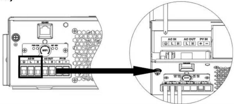

WARNING:
Be sure that AC power source is disconnected before attempting to hardwire it to the unit.
- Then, insert AC output wires according to polarities indicated on terminal block and tighten terminal screws. Be sure to connect PE protective conductor ( ) first.
Ground (yellow-green) L → LINE (brown or black) N → Neutral (blue)
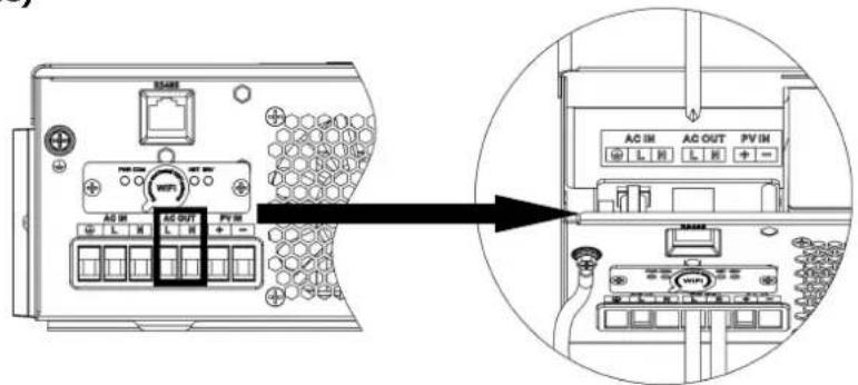
- Make sure the wires are securely connected.
CAUTION: Appliances such as air conditioner are required at least 2~3 minutes to restart because it's required to have enough time to balance refrigerant gas inside of circuits. If a power shortage occurs and recovers in a short time, it will cause damage to your connected appliances. To prevent this kind of damage, please check manufacturer of air conditioner if it's equipped with time-delay function before installation. Otherwise, this inverter/charger will trig overload fault and cut off output to protect your appliance but sometimes it still causes internal damage to the air conditioner.
PV Connectia
CAUTION: Before connecting to PV modules, please install separately a DC circuit breaker between inverter and PV modules.
WARNING! All wiring must be performed by a qualified personnel.
WARNING! It" very important for system safety and efficient operation to use appropriate cable for PV module connection. To reduce risk of injury, please use the proper recommended cable size as below.
| Model Typical | Amperage Cable Size Torque | |||||
| 1.5KVA | 15A 12 AWG | 1.4~1.6 Nm | ||||
| 2.5KVA | 15A | 12 | AWG | 1.4~1.6 Nm | ||
| 3.5KVA | 15A | 12 | AWG | 1.4~1.6 Nm | ||
| 5.5KVA | 18A | 12 | AWG | 1.4~1.6 Nm | ||
| 6.2KVA | 27A | 12 | AWG | 1.4~1.6 Nm | ||
PV Module Selection:
When selecting proper PV modules, please be sure to consider below parameters:
- Open circuit Voltage (Voc) of PV modules not exceeds max. PV array open circuit voltage of inv
- Open circuit Voltage (Voc) of PV modules should be higher than min. battery voltage.
| Solar Charging Mode | |||||
| INVERTER MODEL 1.5KVA 2.5KVA 3.5KVA 5.5KVA 6.2KVA | |||||
| Max. PV Array Open Circuit Voltage 500DC | |||||
| PV Array MPPT Voltage Range | 60VDC~500VDC | ||||
| Max. PV INPUT CURRENT | 15A | 15A | 15A | 18A | 27A |
Take the 450Wp and 550Wp PV module as an example. After considering the above two parameters, the recommended module configurations are listed in the table below.
| Solar Panel Spec.(reference)- 450Wp- Vmp: 34.67Vdc- Imp: 13.82A- Voc: 41.25Vdc- Isc: 12.98A | SOLAR INPUT | Q'ty of panels | Total input power | Inverter Model |
| 2 pcs in serial | 2 pcs | 900 W | 1.5KVA-6.2KVA | |
| 3 pcs in serial | 3 pcs | 1,350 W | ||
| 4 pcs in serial | 4 pcs | 1,800 W | ||
| 5 pcs in serial | 5 pcs | 2,250 W | ||
| 6 pcs in serial | 6 pcs | 2,700 W | ||
| 7 pcs in serial | 7 pcs | 3,150 W | ||
| 8 pcs in serial | 8 pcs | 3,600 W | ||
| 9 pcs in serial | 9 pcs | 4,050 W | ||
| 10 pcs in serial | 10 pcs | 4,500 W | 5.5KVA-6.2KVA | |
| 11 pcs in serial | 11 pcs | 4,950 W | ||
| 12 pcs in serial | 12 pcs | 5,400 W | ||
| 6 pieces in serial and 2 sets in parallel | 12 pcs | 5,400 W | 6.2KVA | |
| 7 pieces in serial and 2 sets in parallel | 14 pcs | 6,300 W | ||
| Solar Panel Spec.(reference)- 550Wp- Vmp: 42.48Vdc- Imp: 12.95A- Voc: 50.32Vdc- Isc: 13.70A | SOLAR INPUT | Q'ty of panels | Total input power | Inverter Model |
| 2 pcs in serial | 2 pcs | 900 W | 1.5KVA-6.2KVA | |
| 3 pcs in serial | 3 pcs | 1,650 W | ||
| 4 pcs in serial | 4 pcs | 2,200 W | ||
| 5 pcs in serial | 5 pcs | 2,750 W | ||
| 6 pcs in serial | 6 pcs | 3,300 W | ||
| 7 pcs in serial | 7 pcs | 3,850 W | ||
| 8 pcs in serial | 8 pcs | 4,400 W | 5.5KVA-6.2KVA | |
| 9 pcs in serial | 9 pcs | 4,950 W | ||
| 4 pieces in serial and 2 sets in parallel | 8 pcs | 4,400 W | ||
| 5 pieces in serial and 2 sets in parallel | 10 pcs | 5,500 W | 6.2KVA | |
| 6 pieces in serial and 2 sets in parallel | 12 pcs | 6,600 W |
PV Module Wire Connection:
Please follow the steps below to implement PV module connection: 1. Remove the insulation sleeve 10 mm from the positive and negative conductors. 2. Check the correct polarity of the connection cable from the PV modules and PV input connectors. Then, connect the positive pole (+) of the connection cable to the positive pole (+) of the PV input connector. Connect the negative pole (-) of the connection cable to the negative pole (-) of the PV input connector.
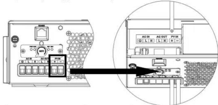
- Make sure the wires are securely connected.
Final Assembly
After connecting all wiring, put the bottom cover back by screwing the two screws as shown below.
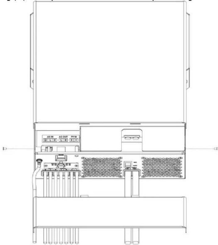
OPERATION
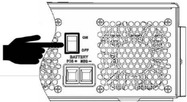
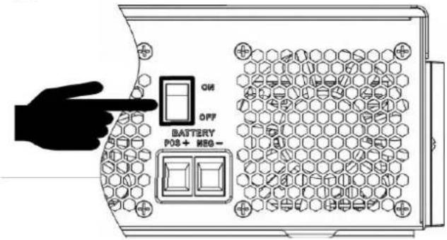
Power ON/OFF
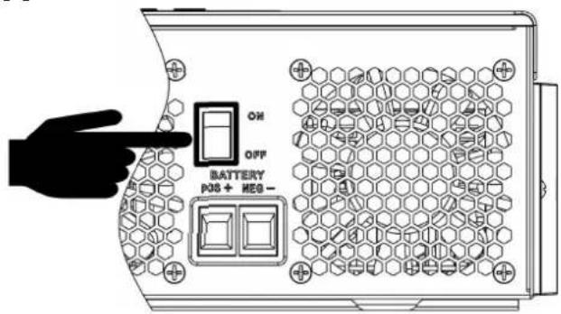
Once the unit has been properly installed and the batteries are connected well, simply press the On/Off switch (located on the button of the case) to turn on the unit.
Operation and Display Panel
The operation and display panel, shown in the chart below, is on the front panel of the inverter. It includes three indicators, four function keys, and an LCD display, indicating the operating status and input/output power information.
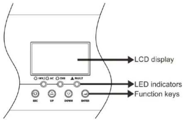
LED Indicator
| LED Indicator Messages | |||
| AC/INV | Green | Solid On | Output is powered by utility in Line mode. |
| Flashing | Output is powered by battery or PV in battery | ||
| CHG | Green | Solid On | Battery is fully charged. |
| Flashing | Battery is charging. | ||
| FAULT | Red | Solid On | Fault occurs in the inverter. |
| Flashing | Warning condition occurs in the inverter. | ||
Function Keys
| Function Key | Description |
| ESC To exit setting mode | |
| UP To go | to previous selection |
| DOWN To go to next selection | |
| ENTER To confirm the selection in setting mode or enter setting mode | |
LCD Setting
After pressing and holding the ENTER button for 3 seconds, the unit will enter setting mode. Press "UP" or "DC" button to select setting programs. Then, press "ENTER" button to confirm the selection or ESC button to exit.
Setting Programs:
| Program | Description Selectable option | ||
| 01 | Output source priority: To configure load power source priority | Utility first (default)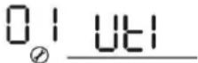 | Utility will provide power to the loads as first priority.Solar and battery energy will provide power to the loads only when utility power is not available. |
Solar first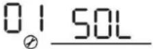 | Solar energy provides power to the loads as first priority.If solar energy is not sufficient to power all connected loads,battery energy will supply power the loads at the same time.Utility provides power to the loads only when any one condition happens:- Solar energy is not available- Battery voltage drops to either low-level warning voltage or the setting point in program 12. | ||
SBU priority | Solar energy provides power to the loads as first priority.If solar energy is not sufficient to power all connected loads, battery energy will supply power to the loads at the same time.Utility provides power to the loads only when battery voltage drops to either low-level warning voltage or the setting point in program 12. | ||
SUB priority . . | Solar energy is charged first and then power to the loads.If solar energy is not sufficient to power all connected loads, Utility energy will supply power to the loads at the same time. | ||
SUF priority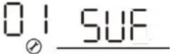 | If solar energy is sufficient to all connected loads and charge battery, the solar energy could feedback to the gridIf solar energy is not sufficient to power all connected loads, utility energy will supply power to the loads at the same time. | ||
| 02 | Maximum charging current: To configure total charging current for solar and utility chargers.(Max. charging current = utility charging current + solar charging current) | 60A (default) | If selected, acceptable charging current range will be from Max. AC charging current to Max. charging current of SPEC, but it shouldn't be less than the AC charging current (program 11) |
| 03 AC | input voltage range | Appliances (default)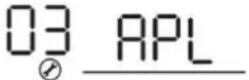 | If selected, acceptable AC input voltage range will be within 90-280VAC. |
UPS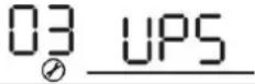 | If selected, acceptable AC input voltage range will be within 170-280VAC. | ||
Generator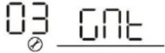 | If selected, acceptable AC input voltage range will be within 170-280VAC and compatible with generators.Note: Because generators are unstable, maybe the output of inverter will be unstable too. | ||
| 05 Battery type | AGM (default)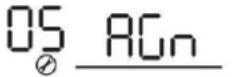 | FloodedOS Fld | |
User-Defined | If "User-Defined" is selected, battery charge voltage and low DC cut-off voltage can be set up in program 26, 27 and 29. | ||
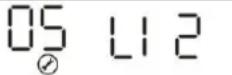 | Support PYLON US2000 Protocol 3.5 Version | ||
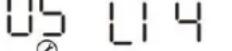 | Standard communication Protocol form inverter supplier | ||
Lithium battery without communication | If "LIB" is selected, the battery default value is fit for lithium battery without communication battery charge voltage and low DC cut-off voltage can be set up in program 26,27 and 29. | ||
| 06 | Auto restart when overloa occurs | Restart disable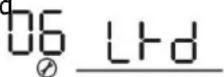 | Restart enable (default)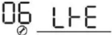 |
| 07 | Auto restart when over temperature occurs | Restart disable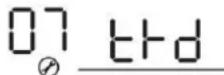 | Restart enable (default)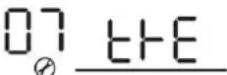 |
| 08 Output voltage | 220V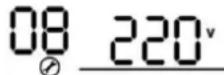 | 230V (default)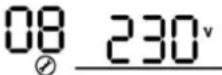 | |
240V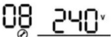 | |||
| 09 Output frequency | 50Hz (default) 60Hz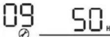 | 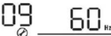 | |
| 10 | Auto bypassWhen selecting "auto", if the mains power is normit will automatically bypass even if the switch is off. | manual(default)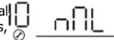 | auto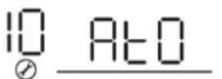 |
| 11 | Maximum utility charging current | 30A (default)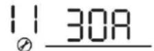 If selected, acceptable charging current range will be within 2-Max. AC charging current of SPEC. If selected, acceptable charging current range will be within 2-Max. AC charging current of SPEC. | |
| 12 | Setting voltage point back to utility source when selecting "SBU priority" or "Solar first" in program 01. | 48V models(program 5 is not LIB):46V (default)Setting range is from 44.0V to 57.2V for 48v model, but the max setting value must be less than the value of program13.48V models(program 5 is LIB):52V (default)Setting range is from 44.0V to 57.2V for 48v model, but the max setting value must be less than the value of program13.24V models(program 5 is LIB):23V (default)Setting range is from 22.0V to 28.6V for 24v model, but The max setting value must be less than the value of program13.24V models(program 5 is LIB):26V (default)Setting range is from 22.0V to 28.6V for 24v model, but The max setting value must be less than the value of program13. | |
| 13 | Setting voltage point back to battery mode when selecting "SBU priority" or "Solar first" in program 01. | Battery fully charged (default)13BATTFUL | 48V models:Setting range is from 48V to full (the value of program26-0.4V), but the max setting value must be more than the value of program12.24V models:Setting range is from 24V to full (the value of program26-0.4V), but the max setting value must be more than the value of program12. |
| 16 | Charger source priority:To configure charger source priority | If this inverter/charger is working in Line, Standby or Fault mode, charger source can be programmed as below: | |
Solar first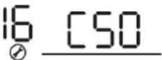 | Solar energy will charge battery as first priority.Utility will charge battery only when solar energy is not available. | ||
Solar and Utility (default)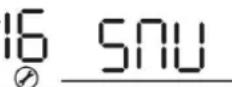 | Solar energy and utility will charge battery at the same time. | ||
Only Solar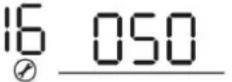 | Solar energy will be the only charger source no matter utility is available or not. | ||
| If this inverter/charger is working in Battery mode, only solar can charge battery. Solar energy will charge battery if it's available and sufficient. | |||
| 18 | Buzzer mode | Mode1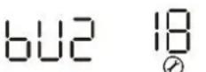 nd1 nd1 | Buzzer mute |
Mode2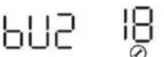 nd2 nd2 | The buzzer sounds when the input source changes or there is a specific warning or fault | ||
Mode3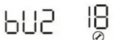 nd3 nd3 | The buzzer sounds when there is a specific warning or fault | ||
Mode4(default)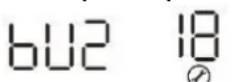 nd4 nd4 | The buzzer sounds when there is a fault | ||
| 19 | Auto return to default display screen | Return to default display screen (default)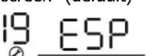 | If selected, no matter how users switch display screen, it will automatically return to default display screen (Input voltage /output voltage) after no button is pressed for 1 minute. |
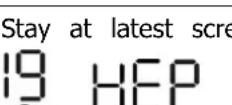 | If selected, the display screen will stay at latest screen user finally switches. | ||
| 20 Backlight control | Backlight on (default)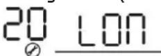 | Backlight off20 LOF | |
| 23 | Overload bypass:When enabled, the unit will transfer to line mode if overload occurs in battery mode. | Bypass disable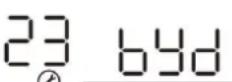 | Bypass enable(default)23 BYE |
| 25 | Modbus ID Setting | Modbus ID Setting Range: 001(default)~247 | |
| 26 | Bulk charging voltage (C.V voltage) | If self-defined is selected in program 5, this program can be set up. But the setting value must be more than or equal the value of program27. Increment of each click is 0.1V.24V models(program 5 is not Lib): Default 28.2V, setting range is from 24.0V to 31.0V,24V models(program 5 is Lib): Default 28.2V, setting range is from 24.0V to 29.0V,48V models(program 5 is not Lib): Default 56.4V, setting range is from 48.0V to 62.0V,48V models(program 5 is Lib): Default 56.4V, setting range is from 48.0V to 58.0V. | |
| 27 | Floating charging voltage | If self-defined is selected in program 5, this program can be set up.24V models(program 5 is not Lib) default setting: 27.0VSetting range is from 24.0V to the value of program 2624V models(program 5 is Lib) default setting: 28.2.0VSetting range is from 24.0V to the value of program 2648V models(program 5 is not Lib) default setting: 54.0VSetting range is from 48.0V to the value of program 2648V models(program 5 is Lib) default setting: 56.4.0VSetting range is from 48.0V to the value of program 26 | |
| 29 | Low DC cut-off voltage | If self-defined is selected in program 5, this program can be set up.The setting value must be less than the value of program12.Increment of each click is 0.1V.Low DC cut-off voltage will be set up. Setting value no matter what percentage of load is connected.24V models default(program 5 is not LIB) setting: 21.0vSetting range is from 20.0V to 27.0V24V models default(program 5 is LIB) setting: 25.0vSetting range is from 20.0V to 27.0V48V models default(program 5 is not LIB) setting: 42.0VSetting range is from 40.0V to 54.0V48V models default(program 5 is LIB) setting: 50.0VSetting range is from 40.0V to 54.0V | |
| 32 | Bulk charging time (C.V stage) | Automatically (Default):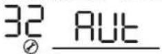 | If selected, inverter will judge this charging time automatically. |
5 min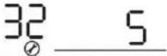 | The setting range is from 5 min to 900 min. Increment of each click is 5 min. | ||
900 min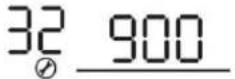 | |||
| If "USE" is selected in program 05, this program can be set up. | |||
| 33 Battery equalization | Battery equalization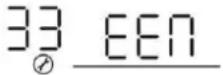 | Battery equalization disable (default)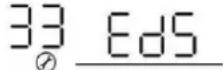 | |
| If "Flooded" or "User-Defined" is selected in program 05, this program can be set up. | |||
| 34 | Battery equalization voltage |     | |
| 35 | Battery equalized time | 60min (default)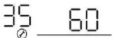 | Setting range is from 0 min to 900min. |
| 36 | Battery equalized timeout | 120min (default)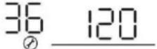 | Setting range is from 0min to 900 min. |
| 37 Equalization interval | 30days (default)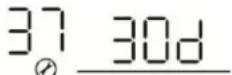 | Setting range is from 1 to 90 days. | |
| 39 | Equalization activated immediately | Enable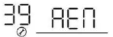 | Disable (default)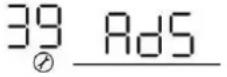 |
 | |||
| this time, will not be shown in LCD main page.. | |||
| 41 | Automatic activation for lithium battery | 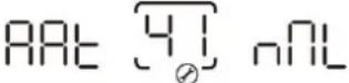 | Disable automatic activation (default) |
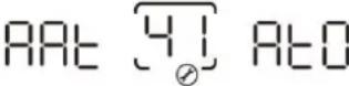 | When Program05 is selected "LIX" as lithium battery and when the battery is not detected, the unit will activate automatically the lithium battery at a time. If you want to activate automatically the lithium battery, you must restart the unit. | ||
| 42 | Manual activation for lithium battery |  | Default: disable activation |
 | When Program05 is selected "LIX" as lithium battery, when the battery is not detected, If you want to activate the lithium battery at a time, you could selected it. | ||
| 43 | Setting SOC point back to utility source when selecting "SBU priority" or "Solar first" in program 01 | 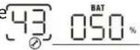 | Default 50%, 5%~50% Settable,but the minimum setting value must be more than the value of program 45. |
| 44 | Setting SOC point back to battery mod when selecting "SBU priority" or "Solar first "in program 01 | 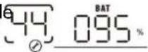 | Default 95%, 60%~100% Settable |
| 45 Low | DC cut-off SOC | 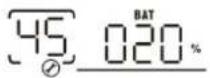 | Default 20%, 3%~30% Settable,but the max setting value must be less than the value of program 43. |
| 46 | Maximum discharge current protection |  | Default OFFDisable current discharge current protection function |
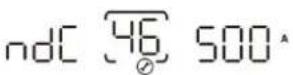 | Only available in Single model.When utility is available, it turns to utility model and battery discharge stops after the battery discharge current exceeded the setting value.When utility is unavailable, warning occurs and battery discharge lasts after the battery discharge current exceeded the setting value. | ||
| 48 | Lithium activation time | 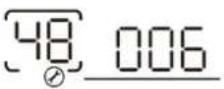 | Default 6s;Set range is from 6s to 300s. |
BATTERY EQUALIZATION
The equalization function is added into the charge controller. It reverses the buildup of negative chemical effects like stratification, a condition where acid concentration is greater at the bottom of the battery than at the top. Equalization also helps to remove sulfate crystals that might have built up on the plates. If left unchecked, this condition, called sulfation, will reduce the overall capacity of the battery. Therefore, it is recommended to equalize the battery periodically.
- How to Apply Equalization Function
You must enable the battery equalization function in the monitoring LCD setting program 33 first. Then, you may apply this function in the device by either one of the following methods:
- Setting equalization interval in program 37.
- Activating equalization immediately in program 39.
- When to Equalize
In float stage, when the set equalization interval (battery equalization cycle) is reached, or equalization is activated immediately, the controller will start to enter the Equalize stage.
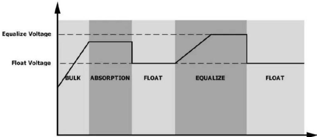
● Equalize charging time and timeout
In the Equalize stage, the controller will supply power to charge the battery as much as possible until the battery voltage rises to the battery equalization voltage. Then, constant-voltage regulation is applied to maintain the battery voltage at the battery equalization voltage. The battery will remain in the Equalize stage until the set battery equalized time is reached.
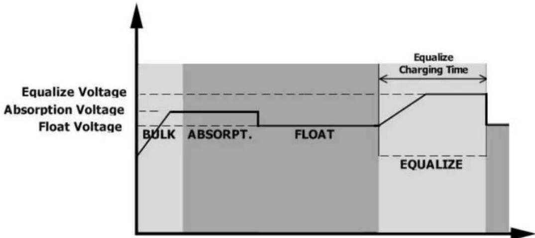
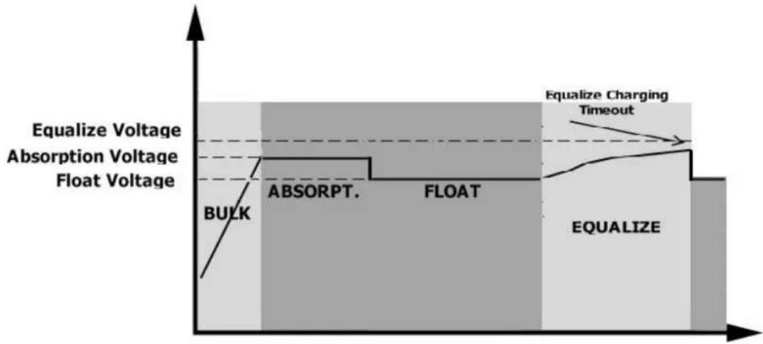
However, in the Equalize stage, when the battery equalized time expires and the battery voltage does not rise to the battery equalization voltage point, the charge controller will extend the battery equalized time until the battery voltage achieves the battery equalization voltage. If the battery voltage is still lower than the battery equalization voltage when the battery equalized timeout setting is over, the charge controller will stop equalization and return to the float stage.
SETTING FOR LITHIUM BATTERY
Lithium Battery Connection
If choosing a lithium battery for the inverter, you are allowed to use only the lithium battery that we have configured. There are two connectors on the lithium battery: the RS485 port of the BMS and the power cable.
Please follow the steps below to implement the lithium battery connection:
1). Assemble the battery terminal based on the recommended battery cable and terminal size (same as lead-acid, see section Lead-acid Battery connection for details). 2). Connect the end of the RS485 port of the battery to the BMS (RS485) communication port of the inverter.
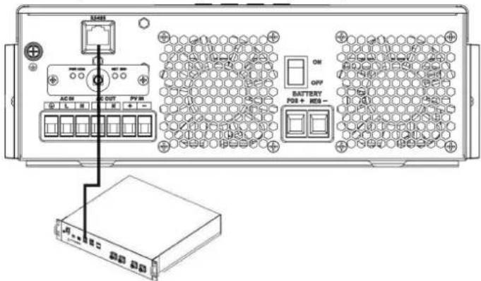
Fig 1
Lithium battery communication and setting
If choosing a lithium battery, make sure to connect the BMS communication cable between the battery and the inverter. This communication cable delivers information and signals between the lithium battery and the inverter. This information is listed below:
- Re-configure charging voltage, charging current, and battery discharge cut-off voltage according to the lithium battery parameters.
- Have the inverter start or stop charging according to the status of the lithium battery.
Connect the end of the RS485 of the battery to the RS485 communication port of the inverter.
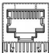
Make sure the lithium battery RS485 port connects to the inverter is Pin to Pin. The communication cable is inside the package, and the inverter RS485 port pin assignment is shown below:
| Pin number | RS485 Port |
| PIN1 RS485-B | |
| PIN2 RS485-A | |
| PIN7 RS485-A | |
| PIN8 RS485-B |
LCD setting
After connecting, you need to complete and confirm some settings as follows:
1) Select program 05 as the lithium battery type. 2) Confirm the setting values of programs 41/42/43/44/45.
Note: Programs 43/44/45 are only available with successful communication; they will replace the functions of programs 12/13/29, and at the same time, programs 12/13/29 become unavailable.
LCD Display
If communication between the inverter and battery is successful, some information will be shown on the LCD as follows:
| Item Description LCD display | ||
| 1 Communication successful icon | 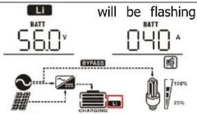 | |
| 2 Max lithium battery charging voltage | 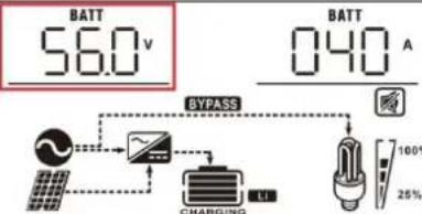 Max lithium battery charging voltage is 56.0V. Max lithium battery charging voltage is 56.0V. | |
| 3 Max lithium battery charging current | 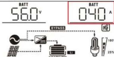 Max lithium battery charging current is 40A. Max lithium battery charging current is 40A. | |
| 4 Lithium battery discharging is forbidden | Li will flash once every 1 second | |
| 5 Lithium battery charging is forbidden | Li will flash once every 2 second | |
| 6 Lithium battery SOC(%) | 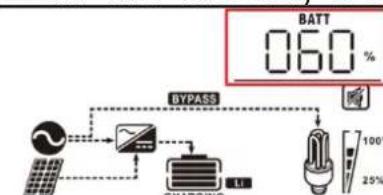 Lithium battery SOC is 63AH and 60% Lithium battery SOC is 63AH and 60% | |
Setting for PYLON US2000 lithium battery
1). PYLONTECH US2000 lithium battery setting:
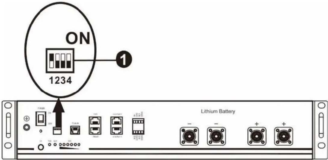
Dip Switch: There are 4 Dip Switches that set different baud rates and battery group addresses. If a switch position is turned to the "OFF" position, it means "0". If a switch position is turned to the "ON" position, it means "1".
Dip 1 is "ON" to represent the baud rate 9600.
Dip 2, 3, and 4 are reserved for the battery group address.
Dip switches 2, 3, and 4 on the master battery (first battery) are used to set up or change the group address.
NOTE: "1" is the upper position and "0" is the bottom position.
2). Installation process
Step 1. Use the RS485 cable to connect the inverter and lithium battery as shown in Fig 1.
Step 2. Switch on the lithium battery.
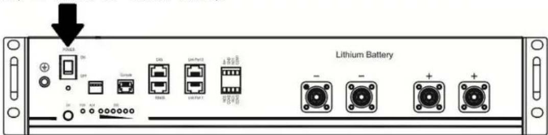
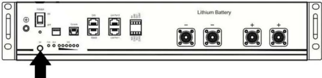
Step 3. Press for more than three seconds to start the lithium battery; power output is ready.
Step 4. Turn on the inverter.
Step 5. Be sure to select battery type as "Li2" in LCD program 5.
If communication between the inverter and battery is successful, the battery icon on the LCD display will light up.
Setting for lithium battery without communication
This suggestion is used for lithium battery applications and to avoid lithium battery BMS protection without communication. Please complete the following settings:
- Before starting the settings, you must obtain the battery BMS specification.
A. Max charging voltage B. Max charging current C. Discharging protection voltage
- Set battery type as "LIB".
| 05 Battery type | AGM (default) Flooded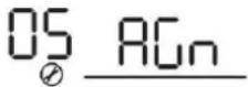 | OS FLD |
| User-Defined If "User-Defined" is selected, batterycharge voltage and low DC cut-offvoltage can be set up in program 26,27 and 29. | ||
Lithium battery withoutcommunication | If "LIB" is selected, the battery defaultvalue is fit for lithium battery withoutcommunication battery charge voltageand low DC cut-off voltage can be setup in program 26,27 and 29. | |
- Set C.V voltage as Max charging voltage of BMS - 0.5V.
| 26 | Bulk charging voltage (C.V voltage) | If self-defined is selected in program 5, this program can be set up. But the setting value must be more than or equal the value of program27. Increment of each click is 0.1V.24V models: Default 28.2V, setting range is from 24.0V to 30.0V ,48V models: Default 56.4V, setting range is from 48.0V to 62.0V. |
- Set floating charging voltage to C.V voltage.
| 27 | Floating charging voltage | If self-defined is selected in program 5, this program can be set up.24V models default setting: 27.0VSetting range is from 24.0V to the value of program 2648V models default setting: 54.0VSetting range is from 48.0V to the value of program 26 |
- Set Low DC cut-off voltage to be greater than or equal to the discharging protection voltage of BMS + 2V.
| 29 | Low DC cut-off voltage | If self-defined is selected in program 5, this program can be The setting value must be less than the value of program12. Increment of each click is 0.1V.Low DC cut-off voltage will be setting value no matter what percentage of load is connected. 24V models default setting: 21.0vSetting range is from 20.0V to 27.0V48V models default setting: 42.0VSetting range is from 40.0V to 54.0V |
- Set Max charging current, which must be less than the Max charging current of BMS.
| 02 | Maximum charging current: To configure total charging current for solar and utility chargers. (Max. charging current = utility charging current + solar charging current) | 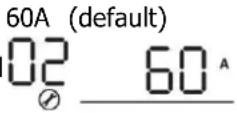 | If selected, acceptable charging current range will be within 1- Max. charging current of SPEC, but it shouldn't be less than the AC charging current (program 11) |
- Set the voltage point to return to utility source when selecting "SBU priority" or "Solar first" in program 01. The setting value must be ≥ Low DC cut-off voltage + 1V, otherwise the inverter will give a warning of low battery voltage.
| 12 | Setting voltage point back to utility source when selecting “SBU priority” or “Solar first” in program 01. | 48V models:46V (default)Setting range is from 44.0V to 57.2V for 48v model, but the max setting value must be less than the value of program13. |
| 24V models:23V (default)Setting range is from 22.0V to 28.6V for 24v model, but The max setting value must be less than the value of program13. |
Remark:
- It is better to complete the settings without turning on the inverter (just let the LCD display, no output).
- After completing the settings, please restart the inverter.
Fault Reference Code
| Fault Code | Fault Event Icon on | |
| 01 | Over temperature of inverter module |  |
| 02 | Over temperature of DCDC module |  |
| 03 | Battery voltage is too high |  |
| 04 | Over temperature of PV module |  |
| 05 | Output short circuited. |  |
| 06 | Output voltage is too high. |  |
| 07 | Overload time out |  |
| 08 | Bus voltage is too high |  |
| 09 | Bus soft start failed |  |
| 10 | PV over current |  |
| 11 | PV over voltage |  |
| 12 | DCDC over current |  |
| 13 | Over current or surge |  |
| 14 | Bus voltage is too low |  |
| 15 | Inverter failed (Self-checking) |  |
| 18 | Op current offset is too high |  |
| 19 | Inverter current offset is too high |  |
| 20 | DC/DC current offset is too high |  |
| 21 | PV current offset is too high |  |
| 22 | Output voltage is too low |  |
| 23 | Inverter negative power |  |
Warning Indicator
| Warning Code | Warning Event Audible Alarm Icon flashing | ||
| 02 | Temperature is too High | Beep three times every second |  |
| 04 | Low battery Beep once | every second |  |
| 07 | Overload Beep once every 0.5 second | 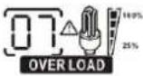 | |
| 10 | Output power derating Beep twice every 3 seconds | 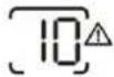 | |
| 14 | Fan blocked None | 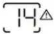 | |
| 15 | PV energy is low Beep | twice every 3 seconds |  |
| 19 | Lithium Battery communication is failed | Beep once every 0.5 second | 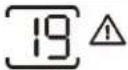 |
| 21 | Lithium Battery over current | None | 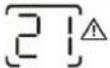 |
| £9 | Battery equalization None | 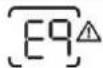 | |
| bP | Battery is not connected | None | 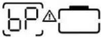 |
SPECIFICATIONS
Table 1 Line Mode Specifications
| INVERTER MODEL | 1.5KVA | 2.5KVA | 3.5KVA | 5.5KVA | 6.2KVA | |
| Input Voltage Waveform Sinusoidal (utility or generator) | ||||||
| Nominal Input Voltage 230Vac | ||||||
| Low Loss Voltage | 170Vac±7V (UPS)90Vac±7V (Appliances) | |||||
| Low Loss Return Voltage | 180Vac±7V (UPS);100Vac±7V (Appliances) | |||||
| High Loss Voltage 280Vac±7V | ||||||
| High Loss Return Voltage 270Vac±7V | ||||||
| Max AC Input Voltage 300Vac | ||||||
| Nominal Input Frequency 50Hz / | 60Hz (Auto detection) | |||||
| Low Loss Frequency 40±1Hz | ||||||
| Low Loss Return Frequency 42±1Hz | ||||||
| High Loss Frequency 65±1Hz | ||||||
| High Loss Return Frequency 63±1Hz | ||||||
| Output Short Circuit Protection | Battery mode: Electronic Circuits | |||||
| Efficiency (Line Mode) | >95% (Rated R load, battery full charged) | |||||
| Transfer Time | 10ms typical (UPS);20ms typical (Appliances) | |||||
| Output power derating:When AC input voltage drops to 95V or170V depending on models, the outputpower will be derated. | 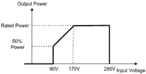 | |||||
Table 2 Inverter Mode Specifications
| INVERTER MODEL | 1.5KVA 2.5KVA 3.5KVA 5.5KVA 6.2KVA | ||||
| Rated Output Power | 1.5KVA1.5KW | 2.5KVA2.5KW | 3.5KVA3.5KW | 5.5KVA5.5KW | 6.2KVA6.2KW |
| Output Voltage Waveform Pure Sine Wave | |||||
| Output Voltage Regulation 230Vac±5% | |||||
| Output Frequency 50Hz or 60Hz | |||||
| Peak Efficiency 94% | |||||
| Surge Capacity 2* rated power for 5 seconds | |||||
| Nominal DC Input Voltage 24Vdc 48Vdc | |||||
| Cold Start Voltage 23.0Vdc 46.0Vdc | |||||
| Low DC Warning VoltageJust for AGM and Flooded@ load < 20%@ 20% ≤ load < 50%@ load ≥ 50% | 22.0Vdc21.4Vdc20.2Vdc | 44.0Vdc42.8Vdc40.4Vdc | |||
| Low DC Warning Return VoltageJust for AGM and Flooded@ load < 20%@ 20% ≤ load < 50%@ load ≥ 50% | 23.0Vdc22.4Vdc21.2Vdc | 46.0Vdc44.8Vdc42.4Vdc | |||
| Low DC Cut-off VoltageJust for AGM and Flooded@ load < 20%@ 20% ≤ load < 50%@ load ≥ 50% | 21.0Vdc20.4Vdc19.2Vdc | 42.0Vdc40.8Vdc38.4Vdc | |||
Table 3 Charge Mode Specifications
| Utility Charging Mode | ||||||
| INVERTER MODEL | 1.5KVA 2. | 5KVA 3.5KVA | 5.5KVA 6. | 2KVA | ||
| Max Charging Current (PV+AC) (@ VI/P=230Vac) | 60Amp 10 | Amp 100Amp | 100Amp 120 | Amp | ||
| Max Charging Current (AC)(@ VI/P=230Vac) | 60Amp 80 | Amp | ||||
| Bulk Charging Voltage | Flooded Battery | 29.2Vdc 58.4Vdc | ||||
| AGM / Gel Battery | 28.2Vdc 56.4Vdc | |||||
| Floating Charging Voltage | 27Vdc 54Vdc | |||||
| Overcharge Protection | 32Vdc 63Vdc | |||||
| Charging Algorithm 3-Step | ||||||
| Charging Curve | 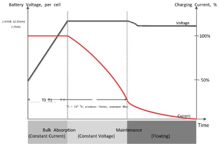 | |||||
| Solar Input | ||||||
| INVERTER MODEL | 1.5KVA 2. | 5KVA 3.5KVA | 5.5KVA 6. | 2KVA | ||
| Rated Power | 2000W | 3000W | 4000W | 5500W | 6500W | |
| Max. PV Array Open Circuit Voltage | 500Vdc | |||||
| PV Array MPPT Voltage Range | 60Vdc~500Vdc | |||||
| Max. Input Current | 15A | 15A | 15A | 18A | 27A | |
| Max. Charging Current(PV) | 60A | 100A | 100A | 100A | 120A | |
Table 4 General Specifications
| INVERTER MODEL | 1.5KVA | 2.5KVA 3.5KVA | 5.5KVA | 6.2KVA | |
| Operating Temperature Range | -10°C to 55°C | ||||
| Storage temperature | -15°C~ 60°C | ||||
| Humidity | 5% to 95% Relative Humidity (Non-condensing) | ||||
| Dimension(D*W*H), mm | 358x295x105 | 438x295x105 | |||
| Net Weight, kg | 5.8 | 6.0 | 6.2 | 8.2 | 8.7 |
Troubleshooting
| Problem LCD | /LED/Buzzer Explanation | / Possible cause What | to do |
| Unit shuts down automatically during startup process. | LCD/LEDs and buzzer will be active for 3 seconds and then complete off. | The battery voltage is too low | 1. Re-charge battery.2. Replace battery. |
| No response after power on. | No indication. | 1. The battery voltage is far too low.2. Battery polarity is connected reversed. | 1. Check if batteries and the wiring are connected well.2. Re-charge battery.3. Replace battery. |
| Mains exist but the unit works in battery mode. | Input voltage is displayed as 0 on the LCD and green LED flashing. | Input protector is tripped is | Check if AC breaker is tripped and AC wiring is connected well. |
| Green LED is flashing | Insufficient quality of AC power.(Shore or Generator) | 1. Check if AC wires are too thin and/or too long.2. Check if generator (if applied) is working well or if input voltage range setting is correct. (UPS→Appliance) | |
| Green LED is flashing | Set "Solar First" as the priority output source. | Change output source priority to Utility first. | |
| When the unit is turned on, internal relay is switched on and off repeatedly. | LCD display and LEDs are flashing | Battery is disconnected. | Check if battery wires are connected well. |
| Buzzer beeps continuously and red LED is on. | Fault code 07 | Overload error. The inverter is overload 110% and time is up. | Reduce the connected load by switching off some equipment. |
| Fault code 05 | Output short circuited. | Check if wiring is connected well and remove abnormal load. | |
| Fault code 02 | Internal temperature of inverter component is over 100°C. | Check whether the air flow of the unit is blocked or whether the ambient temperature is too high. | |
| Fault code 03 | Battery is over-charged. Return to repair center. | ||
| The battery voltage is too high. | Check if spec and quantity batteries are meet requirements. | ||
| Fault code 06/22 | Output abnormal (Inverter voltage below than 190Vac or is higher than 260Vac) | 1. Reduce the connected load.2. Return to repair center | |
| Fault code 08/09/15 | Internal components failed. Return to repair center. | ||
| Fault code 13 Over | current or surge. | Restart the unit, if the error happens again, please return to repair center. | |
| Fault code 14 Bus voltage is too low. | |||
| Another fault code | If the wires is connected well, please return to repair center. | ||
Wi-Fi Plug Pro Quick Installation Guideline
- Schematic diagram of removing and installing the wireless antenna

1.2 Add Datalogger
① Log in to the account and click the Datalogger button. Tap the "+" button on the top-right corner of the datalogger page.
② According to the prompts, type in the information to finish adding the datalogger.
The PN number is located next to the machine appliance label.
(Initial Password: 12345678)
information to finish adding datalogger
The PN number is located next to the machine appliance label.
(Initial Password: 12345678)
2.1 Download the APP
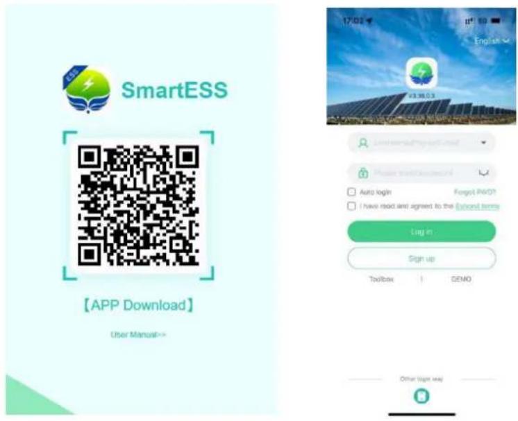
(1) Scan the QR code and download the APP (iPhone App Store; Android phone); (2) Open the APP, click the "Registration" button, and select "Mobile phone Registration" or "Email Registration"; (3) Turn on Bluetooth or WiFi as needed
2.2 Bluetooth connected to the digital collector
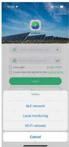
(1) Click the "Toolbox" and select "BLE network" or "Wi-Fi network" as required;
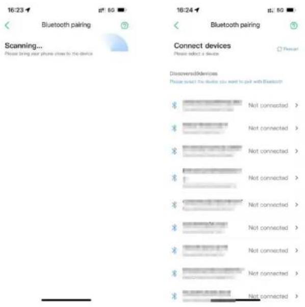
(2) If you choose the Bluetooth distribution network, you will automatically scan the nearby device on the "Bluetooth Pairing" page, find the PN corresponding to the digital collector, and click "Connect".
3.3 Networking Settings
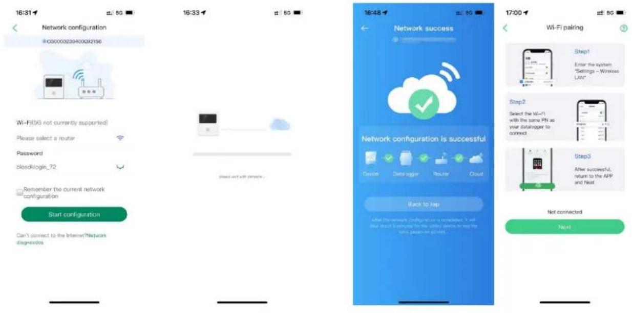
(1) Select the corresponding 2.4G WiFi according to the prompts, fill in the password and click "SI Connecting to the Network"; prompt on the WiFi distribution network reference APP page.
Manufacturer: Shanghaimuxinmuyeyouxiangongsi
Address: Shuangchenglu 803nong11hao1602A-1609shi, baoshanqu, shanghai 200000 CN.
Imported to AUS: SIHAO PTY LTD, 1 ROKEVA STREETEASTWOOD NSW 2122 Australia
Imported to USA: Sanven Technology Ltd., Suite 250, 9166 Anaheim Place, Rancho Cucamonga, CA 91730
| EC | REP |
E-CrossStu GmbH
Mainzer Landstr.69, 60329 Frankfurt am Main.
| UK | REP |
YH CONSULTING LIMITED.
C/O YH Consulting Limited Office 147, Centurion House, London Road, Staines-upon-Thames, Surrey, TW18 4AX
VEVOR®
TOUGH TOOLS, HALF PRICE
Technical Support and E-Warranty Certificate www.vevor.com/support
VEVOR®
TOUGH TOOLS, HALF PRICE
Certificate www.vevor.com/support
HYBRID SOLAR INVERTER
USER MANUAL
MODEL: EM3500-24L/ EM6200-48L
EM 3500-24 L EM 6200-48L
NEED HELP? CONTACT US!
heavy without assistance. Installation
Mounting the unit

WARNING:
OPERATION
On/Off
LED indicator
Figure 1
2.1 Download the app
Baoshanqu, Shanghai 200000 FR.
C/o YH Consulting Limited office 147, centurion House,
London Road, Staines-upon-Thames, Surrey TW18 4AX
VEVOR®
TOUGH TOOLS, HALF PRICE
www.vevor.com/support
Hybrid Solar Inverter
User Manual
Model: EM3500-24L/EM6200-48L
Need help? Contact us!
Mounting the device
as below.

WARNING:
OPERATION
Turning On/Off
LED Indicator
Figure 1
Manufacturer: shanghaimuxinmuyeyouxiangongsi
Address: Subscribe 803 Nong 11 Hao 1602A-1609 schi,
Baoshanqu, Shanghai 200000 CN.
C/o YH Consulting Limited office 147, centurion House,
London Road, Staines-upon-Thames, Surrey TW18
VEVOR®
TOUGH TOOLS, HALF PRICE
www.vevor.com/support
HYBRID SOLAR INVERTER
USER MANUAL
MODEL: EM3500-24L/EM6200-48L
EM3500 - 24 liters EM6200 48L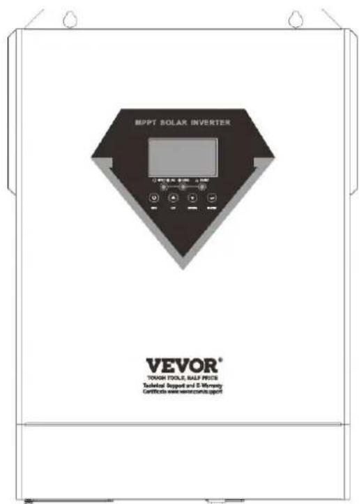
NEED HELP? CONTACT US!

WARNING:
OPERATION
LED indicator
LCD setting
2). Installation process
2.1 Download the APP
C/o YH Consulting Limited office 147, centurion House,
London Road, Staines-upon-Thames, Surrey TW18
VEVOR®
TOUGH TOOLS, HALF PRICE
www.vevor.com/support
HYBRID SOLAR INVERTER
USER MANUAL
MODEL: EM3500-24L/EM6200-48L
EM3500-24L/EM6200-48L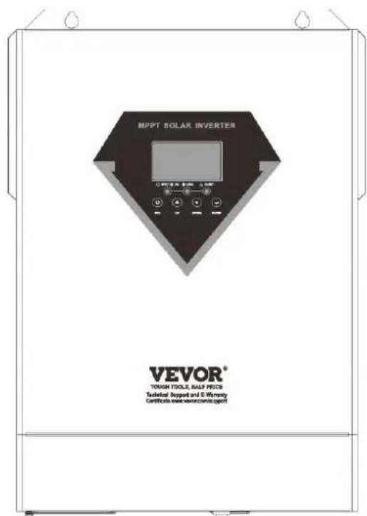

WARNING:
OPERATION
On/Off
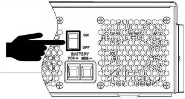
LED Indicator
3.3 Network Settings
Manufacturer: shanghaimuxinmuyeyouxiangongsi
C/o YH Consulting Limited office 147, centurion House, London Road, Staines-upon-Thames, Surrey TW18
VEVOR®
TOUGH TOOLS, HALF PRICE
www.vevor.com/support
HYBRID SOLAR INVERTER
USER MANUAL
MODEL: EM3500-24L / EM6200-48L
EM 3500 - 24 liters, EM 6200 - 48 liters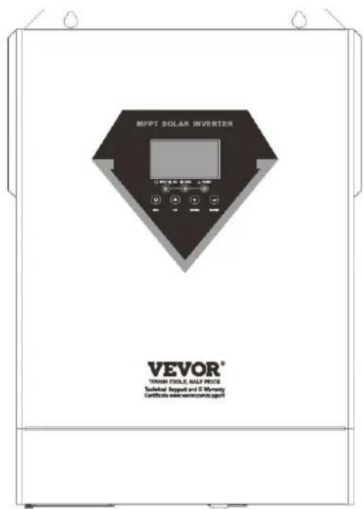
NEED HELP? CONTACT US
Installation of the device
As below.
OPERATION
LED indicator
SETTING FOR LITHIUM BATTERY
Manufacturer: Shanghai Muxin Muye Co., Ltd.
Address: Shuangcheng Road 803, Lane 11, No. 1602A-1609,
Baoshan District, Shanghai 200000, China.
Imported into Australia: SHAOO PTY LTD,
1 Rokeva Street, Woodlands NSW 2122, Australia
C/o YH Consulting Limited, Office 147, Centurion House,
London Road, Staines-upon-Thames, Surrey TW18
VEVOR®
TOUGH TOOLS, HALF PRICE
www.vevor.com/support
Hybrid Solar Inverter
User Manual
MODEL: EM3500-24L/EM6200-48L
NEED HELP? CONTACT US!
Mounting the unit

WARNING:
OPERATION
Turning on/off
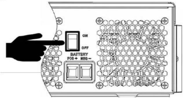
LED indicator
SETTING FOR LITHIUM BATTERY
Fig 1
Lithium battery communication and settings
LCD settings
2.1 Download the APP
3.3 Network settings
Manufacturer: shanghaimuxinmuyeyouxiangongsi
C/o YH Consulting Limited office 147, centurion House, London Road q staines-upon-Thames, surrevq TW18
VEVOR®
TOUGH TOOLS, HALF PRICE
www.vevor.com/support
HYBRID SOL INVERTERARE
ANVÄNDARE MANUELL
MODELL:EM3500-24L/EM6200 -48L
BEHOV HJÄLP ? KONTAKTA USA !
www.vevor. se/support

WARNING:
DRIFT
Power ON/OFF
LED indicator
ENVIRONMENT FOR LITHIUM BATTERY
Lithium battery connection
LCD setting
2). Handling of installation
2.1 Download the APP
Manufacturer: shanghaimuxinmuyeyouxiangongsi
Address: shuangchenglu 803 nong 11 hao 1602A-1609 shi,
Baoshanqu, shanghai 200000 SV.
Imported to AUS: SIHAO PTY LTD, 1 ROKEVA STREET EASTWOOD NSW 2122 Australia
Imported to USA: sanven Technology Ltd., Suite 250, 9166 Anaheim Place, Rancho Cucamonga, CA 91730
| EC | REP |
E-crossstu GmbH
Mainzer Landstr.69, 60329 Frankfurt am Main.
| UK | REP |
YH CONSULTING LIMITED.
C/o YH Consulting Limited office 147, centurion House,
London Road, Staines-upon-Thames, Surrey, TW18
VEVOR®
TOUGH TOOLS, HALF PRICE
- HYBRID SOLAR INVERTER
- USER MANUAL
- VEVOR®
- NEED HELP? CONTACT US
- WARNING: DANGER OF ELECTRICAL SHOCK
- WARNING: DO NOT LIFT HEAVY OBJECTS UNASSISTED
- INSTALLATION
- TRANSPORT AND STORAGE
- PRODUCT OVERVIEW
- UNPACKING AND INSPECTION
- PREPARATION
- MOUNTING THE UNIT
- BATTERY CONNECTION
- AC INPUT/OUTPUT CONNECTION
- WARNING
- PV CONNECTIA
- PV MODULE SELECTION
- PV MODULE WIRE CONNECTION
- FINAL ASSEMBLY
- OPERATION
- POWER ON/OFF
- OPERATION AND DISPLAY PANEL
- LCD SETTING
- BATTERY EQUALIZATION
- HOW TO APPLY EQUALIZATION FUNCTION
- WHEN TO EQUALIZE
- ● EQUALIZE CHARGING TIME AND TIMEOUT
- SETTING FOR LITHIUM BATTERY
- LITHIUM BATTERY CONNECTION
- LITHIUM BATTERY COMMUNICATION AND SETTING
- CONNECT THE END OF THE RS485 OF THE BATTERY TO THE RS485 COMMUNICATION PORT OF THE INVERTER
- LCD DISPLAY
- SETTING FOR PYLON US2000 LITHIUM BATTERY
- SETTING FOR LITHIUM BATTERY WITHOUT COMMUNICATION
- REMARK
- WARNING INDICATOR
- SPECIFICATIONS
- WI-FI PLUG PRO QUICK INSTALLATION GUIDELINE
- ADD DATALOGGER
- DOWNLOAD THE APP
- BLUETOOTH CONNECTED TO THE DIGITAL COLLECTOR
- NETWORKING SETTINGS
- TOUGH TOOLS, HALF PRICE
- ON/OFF
- MOUNTING THE DEVICE
- TURNING ON/OFF
- NETWORK SETTINGS
- INSTALLATION OF THE DEVICE
- LITHIUM BATTERY COMMUNICATION AND SETTINGS
- LCD SETTINGS
- HYBRID SOL INVERTERARE
- ANVÄNDARE MANUELL
- BEHOV HJÄLP ? KONTAKTA USA
- DRIFT
- ENVIRONMENT FOR LITHIUM BATTERY
Brand : Vevor
Model : EM3500-24L
Category : Solar inverter