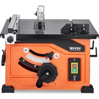
WTS210F - Saw Vevor - Free user manual and instructions
Find the device manual for free WTS210F Vevor in PDF.


| Product Type | Table Saw |
| Brand | Vevor |
| Model | WTS210F |
| Motor Power | 1200 W |
| Supply Voltage | 230-240 V ~ 50 Hz |
| No-load Speed (n0) | 4800 rpm |
| Blade Diameter | 210 mm |
| Blade Bore | 30 mm |
| Blade Thickness | 2.6 mm |
| Number of Teeth | 24 |
| Max Cutting Height (at 90°) | 45 mm |
| Max Cutting Height (at 45°) | 27 mm |
| Blade Tilt | 0 - 45° (continuously adjustable) |
| Extraction Connection Diameter | 35 mm |
| Operating Mode | S6 40% (10 min cycle) |
| Sound Pressure Level (LpA) | 92.4 dB(A), uncertainty K=3 dB |
| Sound Power Level (LWA) | 105.4 dB(A), uncertainty K=3 dB |
| Main Functions | Ripping, cross-cutting, mitre cutting, bevel cutting, compound mitre cutting, rabbeting, grooving, resawing |
| Integrated Safety | Blade guard, riving knife, safety switch, overload reset button |
| Maintenance and Cleaning | Unplug before cleaning; use a damp cloth and mild soap; occasional lubrication of rods and gears with SAE 20/30 oil or WD-40 |
| Spare Parts and Repairability | Replacement saw blade (Ø210×Ø30×2.6 mm, 24 teeth), carbon brushes, switch; contact VEVOR authorized service |
Frequently Asked Questions - WTS210F Vevor
User questions about WTS210F Vevor
0 question about this device. Answer the ones you know or ask your own.
Ask a new question about this device
Download the instructions for your Saw in PDF format for free! Find your manual WTS210F - Vevor and take your electronic device back in hand. On this page are published all the documents necessary for the use of your device. WTS210F by Vevor.
USER MANUAL WTS210F Vevor
Technical Support and E-Warranty Certificate www.vevor.com/support
ELECTRIC TABLE SAW USER MANUAL
MODEL:WTS210F
We continue to be committed to provide you tools with competitive price. "Save Half", "Half Price" or any other similar expressions used by us only represent of savings you might benefit from buying certain tools with us compared major top brands and does not necessarily mean to cover all categories of tools us. You are kindly reminded to verify carefully when you are placing an order v are actually saving half in comparison with the top major brands.
VEVOR®
TOUGH TOOLS, HALF PRICE
ELECTRIC TABLE SAW
MODEL:WTS210F
natural_image
Industrial machine with workpiece and control panel (no visible text or symbols)NEED HELP? CONTACT US!
Have product questions? Need technical support? Please feel fr contact us:
Technical Support and E-Warranty Certificate www.vevor.com/support
This is the original instruction, please read all manual instruction carefully before operating. VEVOR reserves a clear interpretation user manual. The appearance of the product shall be subject to product you received. Please forgive us that we won't inform you there are any technology or software updates on our product.
Table of Contents
General Safety Rules----3
Safety Instructions for Table Saws----
Additional Safety Rules----7
Symbols----10
Glossary of Terms----13
Getting To Know Your Table Saw----
Unpacking And Checking Contents----19
Assembly----17
Storage, Transporting, and Mounting----1
Adjustments----20
Basic Table Saw Operation----20
Maintaining Your Table Saw----2
Troubleshooting----29
TECHNICAL DATA----30
WARNING
Some dust created by power sanding, sawing, grinding, drilling, and other construction activities contains chemicals known to cause cancer, birth defects or other reproductive harm.
Some examples of these chemicals are:
. Lead from lead-based paints,
. Crystalline silica from bricks and cement and
other masonry products, and
. Arsenic and chromium from chemically treated lumber .
Your risk from these exposures varies, depending on how often you do this type of work. To reduce your exposure to these chemicals: work in a well ventilated area, and work with approved safety equipment, such as those dust masks that are specially designed to filter out microscopic particles.
Avoid prolonged contact with dust from power sanding, sawing, grinding, drilling, and other construction activities. Wear protective clothing and wash exposed areas with soap and water. Allowing dust to get into your mouth or eyes or to lie on the skin may promote absorption of harmful chemicals.
General Safety Rules

Read all safety warnings, instructions, illustrations and specifications pro with this power tool. Failure to follow all instructions listed below may res
electric shock, fire and/or serious injury.
SAVE ALL WARNINGS AND INSTRUCTIONS FOR FUTURE REFERENCE.
The term "power tool" in the warnings refers to your mains-operated (corded) power tool or operated (cordless) power tool.
WORK AREA SAFETY
Keep work area clean and well lit. Clutter dark areas invite accidents.
Do not operate power tools in explosive spheres, such as in the presence of flammable liquids, gases or dust. Power tools cr sparks which may ignite the dust or fumes
Keep children and bystanders away while operating a power tool. Distractions can ca you to lose control.
ELECTRICAL SAFETY
Power tool plugs must match the outlet. Never modify the plug in anyway. Do no any adapter plugs with earthed (grounded power tools. Unmodified plugs and matching outlets will reduce risk of electric shock.
Avoid body contact with earthed or groul surfaces, such as pipes, radiators, ranges and refrigerators. There is an increased ris electric shock if your body is earthed or gr
Do not expose power tools to rain or winditions. Water entering a power tool will include the risk of electric shock.
Do not abuse the cord. Never use the c carrying, pulling or unplugging the power Keep cord away from heat, oil, sharp ed moving parts. Damaged or entangled cords crease the risk of electric shock.
When operating a power tool outdoors, u an extension cord suitable for outdoor us Use of a cord suitable for outdoor use red the risk of electric shock.
If operating a power tool in a damp local unavoidable, use a Ground Fault Circuit Irupter (GFCI) protected supply. Use of an GFCI reduces the risk of electric shock.
PERSONAL SAFETY
Stay alert, watch what you are doing and common sense when operating a power tool. Do not use a power tool while you are
under the influence of drugs, alcohol or medication. A moment of inattention while operating power tools may result in serious personal injury
Use personal protective equipment. Always wear eye protection. Protective equipment such as dust mask, non-skid safety shoes, hard hat, hearing protection used for appropriate conditions will reduce personal injuries.
Prevent unintentional starting. Ensure the switch is in the off-position before connecting to power source and / or battery pack, pick up or carrying the tool. Carrying powertools v your finger on the switch or energizing power that have the switch on invites accidents .
Remove any adjusting key or wrench before turning the power tool on. A wrench or a key left attached to a rotating part of the power tool may result in personal injury.
Do not overreach. Keep proper footing and balance at all times. This enables better control of the power tool in unexpected situations.
Dress properly. Do not wear loose clothing jewelry. Keep your hair, clothing and gloves away from moving parts. Loose clothes, jewelry or long hair can be caught in moving par
If devices are provided for the connection of dust extraction and collection facilities, ensure these are connected and properly used. Use of dust collection can reduce dust-related hazards.
Do not let familiarity gained from frequent use of tools allow you to become complacent and ignore tool safety principles. A careless action can cause severe injury within a fraction of a second.
POWER TOOL USE AND CARE
Do not force the power tool. Use the correct power tool for your application. The correct power tool will do the job better and safer at rate for which it was designed.
SAVE THESE INSTRUCTIONS
General Safety Rules
Do not use the power tool if the switch not turn it on and off. Any power tool th not be controlled with the switch is dangerc and must be repaired .
Disconnect the plug from the power sour and/or remove the battery pack, if detach from the power tool before making any a ments, changing accessories, or storing power tools. Such preventive safety measure reduce the risk of starting the power tool a tally.
Store idle power tools out of the reach dren and do not allow persons unfamiliar the power tool or these instructions to date the power tool. Power tools are danger in the hands of untrained users.
Maintain powertools and accessories. Check misalignment or binding of moving parts, breakage of parts and any other condition that may affect the power tool's operation damaged, have the power tool repaired by use. Many accidents are caused by poorly
tained power tools .
Keep cutting tools sharp and clean. Properly maintained cutting tools with sharp cutting edges are less likely to bind and are easier to control
Use the power tool, accessories and tool bit etc. in accordancewiththese instructions, taking into account the working conditions and the work to be performed. Use of the power tool operations different from those intended could result in a hazardous situation.
Keep handles and grasping surfaces dry, clean and free from oil and grease. Slippery handles and grasping surfaces do not allow for safe handling and control of the tool in unexpected situations.
SERVICE
Have your power tool serviced by a qualified repair person using only identical replacement parts. This will ensure that the safety of power tool is maintained.
Safety Instructions for Table Saws
GUARDING RELATED WARNINGS
Keep guards in place. Guards must be in working order and be properly mounted. A guard that is loose, damaged, or is not fur correctly must be repaired or replaced.
Always use saw blade guard, riving knife for every through-cutting operation. For through-cutting operations where the saw bla cuts completely through the thickness of the workpiece, the guard and other safety devices help reduce the risk of injury.
Immediately reattach the guarding system after completing an operation (such as ra beting, dadoing or resawing cuts) which quires removal of the guard, riving knife and/or. The guard, riving knife, and help to reduce the risk of injury.
Make sure the saw blade is not contacting guard, riving knife or the workpiece before t switch is turned on. Inadvertent contact of the items with the saw blade could cause a hazard condition .
Adjust the riving knife as described in this struction manual. Incorrect spacing, positioning and alignment can make the riving knife ineffective in reducing the likelihood of kickback.
For the riving knife and to work, they must engaged in the workpiece.
The riving knife and are ineffective when cutting workpieces that are too short to be engaged with the riving knife and anti-kick-back device. Under these conditions a kickback cannot be prevented by the riving knife and anti-kickback device.
Safety Instructions for Table Saws
Use the appropriate saw blade for the riving knife. For the riving knife to function proper saw blade diameter must match the appropriate riving knife and the body of the saw blade thinner than the thickness of the riving knife, the cutting width of the saw blade must be than the thickness of the riving knife.
CUTTING PROCEDURES WARNINGS
Never place your fingers on the vicinity or in line
with the saw blade. A moment of inattentio slip could direct your hand towards the saw and result in serious personal injury.
Feed the workpiece into the saw blade c ter only against the direction of rotation. ing the workpiece in the same direction tha saw blade is rotating above the table may the workpiece, and your hand, being pulled the saw blade .
Never use the mitre gauge to feed the v piece when ripping and do not use the fence as a length stop when cross cutting the miter gauge. Guiding the workpiece with rip fence and the miter gauge at the same increases the likelihood of saw blade binding kickback.
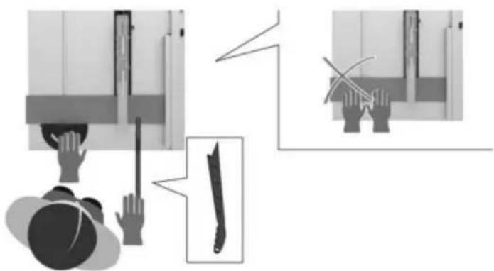
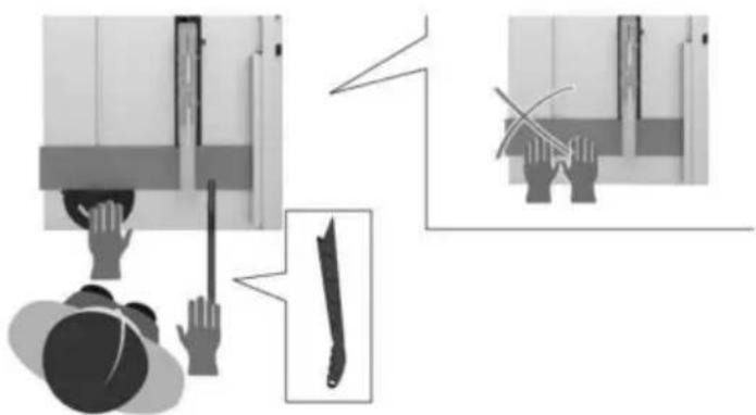
When ripping, always apply the workpiece feeding force between the fence and the blade. Use a push stick when the distant tween the fence and the saw blade is 150 mm, and use a push block when the tance is less than 50 mm. "Work helping" vices will keep your hand at a safe distance the saw blade.
Use only the push stick provided by the ufacturer or constructed in accordance with the instructions. This push stick provides a cient distance of the hand from the saw bl
Never use a damaged or cut push stick. damaged push stick may break causing you hand to slip into the saw blade.
Do not perform any operation “freehand.” ways use either the rip fence or the mit gauge to position and guide the workpiece. “Freehand” means using your hands to support or guide the workpiece, in lieu of a rip fermiter gauge. Freehand sawing leads to motion, binding and kickback.
Never reach around or over a rotating saw blade. Reaching for a workpiece may lead to cidental contact with the moving saw blade.
Provide auxiliary workpiece support to the rear and/or sides of the saw table for long or wide workpieces to keep them level. A lo and/or wide workpiece has a tendency to pivot the table's edge, causing loss of control, saw blade binding and kickback.
Feed the workpiece at an even pace. Do no bend or twist the workpiece. If jamming occurs, turn the tool off immediately, unplug t tool and clear the jam. Jamming the saw bla by the workpiece can cause kickback or stall t motor.
Do not remove pieces of cut-off material while the saw is running. The material may come trapped between the fence or inside the saw blade guard and the saw blade pulling yo fingers into the saw blade. Turn the saw off a wait until the saw blade stops before removing material.
Use an auxiliary fence in contact with the top when ripping workpieces less than 2 m thick. A thin workpiece may wedge under the fence and create a kickback.
KICKBACK CAUSES AND RELATED WARNINGS
Kickback is a sudden reaction of the workpiece to a pinched, jammed saw blade or misaligned of cut in the workpiece with respect to the saw blade or when a part of the workpiece binds between the saw blade and the rip fence or other fixed object.
Most frequently during kickback, the workpiece is lifted from the table by the rear portion of the blade and is propelled towards the operator.
Kickback is the result of saw misuse and/or in rect operating procedures or conditions and can be avoided by taking proper precautions as giv below.
Never stand directly in line with the saw blade. Always position your body on the same side of the saw blade as the fence. Kickback may propel the workpiece at high velocity towards a one standing in front and in line with the saw blade.
SAVE THESE INSTRUCTIONS
Safety Instructions for Table Saws
Never reach over or in back of the saw to pull or to support the workpiece. Acci contact with the saw blade may occur or k may drag your fingers into the saw blade.
Never hold and press the workpiece that being cut off against the rotating saw bl. Pressing the workpiece being cut off against saw blade will create a binding condition ar back .
Align the fence to be parallel with the s blade. A misaligned fence will pinch the wo piece against the saw blade and create kick
Use a feather board to guide the workpiece against the table and fence which making non-through cuts such as rabbeting, dadoing or resawing cuts. A featherboard helps to control the workpiece in the event of a kickback.
Use extra caution when making a cut into blind areas of assembled workpieces. The truding saw blade may cut objects that can kickback.
Support large panels to minimize the risk saw blade pinching and kickback. Large panels tend to sag under their own weight. Support(s) must be placed under all portions of the pa overhanging the table top.
Use extra caution when cutting a workpie that is twisted, knotted, warped or does have a straight edge to guide it with a gauge or along the fence. A warped, knot twisted workpiece is unstable and causes m alignment of the kerf with the saw blade, k and kickback .
Never cut more than one workpiece, stac vertically or horizontally. The saw blade c pick up one or more pieces and cause kick
When restarting the saw with the saw blade, the workpiece, center the saw blade in this so that the saw teeth are not engaged in material. If the saw blade binds, it may lift workpiece and cause kickback when the saw restarted.
Keep saw blades clean, sharp, and with cient set. Never use warped saw blades or saw blades with cracked or broken teeth. Sha and properly set saw blades minimize binding stalling and kickback.
Turn off the table saw and disconnect the power cord when removing the table insert, changing the saw blade or making adjustments to the riving knife, antikickback device or saw blade guard, and when the machine left unattended. Precautionary measures will avoid accidents.
Never leave the table saw running unattended. Turn it off and don't leave the tool until it comes to a complete stop. An unattended running saw is an uncontrolled hazard.
Locate the table saw in a well-lit and level where you can maintain good footing and balance. It should be installed in an area that provides enough room to easily handle the size your workpiece. Cramped, dark areas, and uneven slippery floors invite accidents.
Frequently clean and remove sawdust from under the saw table and/or the dust collecti device. Accumulated sawdust is combustible and may self-ignite.
The table saw must be secured. A table saw that is not properly secured may move or tip over.
Remove tools, wood scraps, etc. from the table before the table saw is turned on. Distraction or a potential jam can be dangerous.
Always use saw blades with correct size and shape (diamond versus round) of arbor holes. Saw blades that do not match the mounting hardware of the saw will run off-center, causing loss control.
Never use damaged or incorrect saw blade mounting means such as flanges, saw blade washers, bolts or nuts. These mounting means were specially designed for your saw for safe eration and optimum performance.
Never stand on the table saw; do not use a stepping stool. Serious injury could occur if tool is tipped or if the cutting tool is accidenta contacted.
Make sure that the saw blade is installed to rotate in the proper direction. Do not use grinding wheels, wire brushes, or abrasive wheels on a table saw. Improper saw blade installation or use of accessories not recommended may cause serious injury.
SAVE THESE INSTRUCTIONS
Additional Safety Rules
MAKE WORKSHOP CHILD-PROOF with pad locks, master switches.
Use only recommended accessories. Use accessories recommended by the manufacture your model. Other accessories maybe hazard Do not use any blade or other cutting t marked for an operating speed less than
R.P.M. Risk of serious injury .
Ensure that blade or other cutting tool, was and arbor nut are installed properly. Refe instructions for removal and installation of the
Never operate the saw unless the proper sert is installed. Make sure the table insert flush or slightly below the table surface at and flush to slightly above at the rear of i
Always inspect table saw prior to every any part of your saw is missing, malfunction has been damaged or broken (such as the switch or other operating control, a safety c or the power cord), cease operat immediate until the particular part is prop repaired or replaced.
Plastic and composition (like hardboard) rterials may be cut on your saw. However since these are usually quite hard and spery, the may not stop a kickback. There be especially attentive to following proper set up and cutting procedures for ripping . Do stand, or permit anyone else to stand, in li with a potential kickback .
Use extra caution when the guard assem removed for resawing, dadoing, rabbeting molding. Replace the guard as soon as that eration is completed.
Use auxiliary facing on miter gauge to increase stability and control. Crosscutting operations are more conveniently worked and with greater safety if an auxiliary wood facing be attached to the miter gauge. See "Rip Fer-iliary Facing."
Avoid awkward operations and hand position Where a sudden slip could cause fingers on move into the sawblade or other cutting too
If you stall or jam the sawblade in the piece, turn saw "OFF" and unplug the to remove the workpiece from the sawblade, check to see if the sawblade is parallel table slots or grooves and if the spread
I proper alignment with the sawblade. If ripping at the time, check to see if the rip fence is with the sawblade. Readjust as indicated.
THINK SAFETY: Safety is a combination of operator common sense and alertness at all times when the table saw is being used.
WARNING The operation of any power tool can result in foreign objects being thrown into the eyes, which can
sult in severe eye damage. Always wea safety goggles that comply with ANSI Z87 .1 (shown on package) before commencing power tool operation.
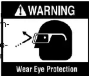
Before each use, review all warnings located on the table saw.
TABLE SAW STAND SAFETY INSTRUCTIONS
WARNING Read al instructions. Failu to follow all instructions list below may result in serious personal injury.
Fully assemble and tighten all the fasteners required for this stand. Also remember to occasionally check the stand and make sure it still tight. A loose stand is unstable and may in use and cause serious injury.
Turn the tool switch off and disconnect the power before mounting the saw to the stand. Unintended startup during assembly can cause injury.
Before operating, make sure that the entire unit is placed on a solid, flat, level surface. Serious injury could occur if the tool is unstable and it tips.
Never stand on the tool or its stand or use a ladder or scaffolding. Serious injury could occur if the tool is tipped or the cutting tool is dentally contacted . Do not store materials on near the tool such that it is necessary to stand the tool or its stand to reach them .
Use only VEVOR replacement parts. Any others may create a hazard.
SAVE THESE INSTRUCTIONS
Motor Specifications & Electrical Requirements
Motor Specifications
In the event of a malfunction or breakdown grounding provides a path of least resistance electric current to reduce the risk of electric. This tool is equipped with an electric cord an equipment-grounding conductor and a growing plug. The plug must be plugged into ing outlet that is properly installed and grou accordance with all local codes and ordinary. This saw is wired for operation on 120 volts alternating current. Before connecting the n cord to a power source, make certain that switch is in the "OFF" position and be sure electric current is of the same characteristics that stamped on the table saw nameplate.
to the ground prong in the attachment plug at the other end.
Connection To A Power Source
This machine must be grounded while in us protect the operator from electric shock.
Plug the power cord into a 120V properly gr type outlet protected by a 15-amp dual-ele time-delay fuse or circuit breaker.
Not all outlets are properly grounded. If you sure that your outlet, as pictured on this paper properly grounded; have it checked by a qu electrician.
WARNING
To avoid electric shock do not touch the metal prongs
on the plug when installing or removing plug to or from the outlet.
WARNING
Failure to properly ground this power tool can cause
electrocution or serious shock, particularly when used near metal plumbing or other objects. If shocked, your reaction could cause your hands to hit the tool.
WARNING
If power cord is worn, cut damaged in any way, have
replaced immediately to avoid shock or f hazard.
Your unit is for use on 230
volts and is equipped with
a 2-conductor cord and
grounding type plug, ap-
proved by Underwriters
Laboratories and the Ca-
nadian Standards Associ-
ation . The ground conductor has a green
and is attached to the tool housing at one
If the outlet you are planning to use for the tool is of the two-prong type, DO NOT RE OR ALTER THE GROUNDING PRONG IN MANNER. Have a qualified electrician replac TWO-prong outlet with a properly grounded THREE-prong outlet. Do not use any adap plugs.
Improper connection of the equipment-ground conductor can result in a risk of electric sh conductor with insulation having an outer su that is green with or without yellow stripes equipment grounding conductor. If repair or placement of the electric cord or plug is no do not connect the equipment grounding co tor to a live terminal.
Check with a qualified electrician or service sonnel if the grounding instructions are not pletely understood, or if in doubt whether the properly grounded.
Extension Cords

Replace damaged cords im mediately. Use of damaged
cords can shock, burn or electrocute .

According to the applicable product liability laws, the
manufacturer of the device does not assu liability
for damages to the product or damages caused by
the product that occurs due to:
- Improper handling
• Non-compliance of the operating instruct
• Repairs by third parties, not by authori service
technicians
• Installation and replacement of non-origin spare
parts
- Application other than specified
- A breakdown of the electrical system that occurs
due to the non-compliance of the electric lations and VDE regulations 0100, DIN 5/VDE0113.
Symbols
Safety Symbols
The purpose of safety symbols is to attract your attention to possible dangers. The safety and the explanations with them deserve your careful attention and understanding. The sym warnings do not, by themselves, eliminate any danger. The instructions and warnings they no substitutes for proper accident prevention measures.
WARNING
Be sure to read and understand all safety instructions in this Owner's Manual, including all safety alert symbols such as "DANGER,"
"WARNING," and "CAUTION" before using this tool. Failure to following all instructions listed below may result in electric shock, fire, and/or serious personal injury.
| The definitions below describe the level of severity for each signal word. Please read to pay attention to these symbols . | |
 | This is the safety alert symbol . It is used to alert you to potential injury hazards. Obey all safety messages that follow this symbol to possible injury or death . |
 | DANGER indicates a hazardous situation which, if not avoided, will in death or serious injury . |
 | WARNING indicates a hazardous situation which, if not avoided, could result in death or serious injury . |
 | CAUTION, used with the safety alert symbol, indicates a hazardous ation which, if not avoided, will result in minor or moderate injury |
Damage Prevention and Information Messages
These inform the user of important information and/or instructions that could lead to equipm other property damage if they are not followed. Each message is preceded by the word as in the example below:
NOTICE: Equipment and/or property damage may result if these instructions are not followed

natural_image
Black circular icon with a stylized white face wearing glasses (no text or symbols)WARNING The operation of any power tools can result in foreign objects being thrown into your eyes, which can result in severe eye damage. Before beginning power tool operation, always wear safety goggles or safety glasses with side shields and a full face shield when needed. We recommend a Wide Vision Safe Mask for use over eyeglasses or standard safety glasses with side shields. Always use eye protection which is marked to comply with ANZ87.1.
Symbols
IMPORTANT: Some of the following symbols may be used on your tool. Please study the learn their meaning. Proper interpretation of these symbols will allow you to operate the t and more safely.
| Symbol | Name | Designation/Explanation |
| V | Volts | Voltage (potential) |
| A | Amperes | Current |
| Hz | Hertz | Frequency (cycles per second) |
| W | Watt | Power |
| kg | Kilograms | Weight |
| min | Minutes | Time |
| s | Seconds | Time |
| Wh | Watt-hours | Battery capacity |
| Ah | Ampere-Hours | Battery capacity |
| ∅ | Diameter | Size of drill bits, grinding wheels, etc. |
| n0 | No load speed | Rotational speed, at no load |
| n | Rated speed | Maximum attainable speed |
| .../min | Revolutions or reciprocation per minute | Revolutions, strokes, surface speed, orbits etc . per minute |
| 0 | Off position | Zero speed, zero torque... |
| → | Arrow | Action in the direction of arrow |
| ~ | Alternating current | Type or a characteristic of current |
| --- | Direct current | Type or a characteristic of current |
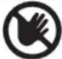 | Risk of injury symbol | Do not reach into the running saw blade |
 | Read manual symbol | Alerts user to read manual |
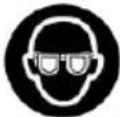 | Wear eye protection symb | Always wear safety goggles or safety gla with side shields and a full face shield operating this product . |
 | Wear a mask | Recommendation for the operator to wear dust mask . |
 | Wear ear protection | Recommendation for the operator to wear hearing protection . |
Symbols (Certification Information)
IMPORTANT: Some of the following symbols for certification information may be used on your tool. Please study them and learn their meaning. Proper interpretation of these symbols you to operate the tool better and more safely.
| Symbol | Designation/Explanation |
 | TÜV / GS conformity mark |
 | CE marking |
Glossary of Terms
ARBOR: The shaft on which a cutting tool mounted.
BARRIER GUARD: An assembly that consists of the mounting fork and two side barriers assembly is intended to provide a physical rier between the operator and the spinning blade.
BEVEL: Blade angle relative to the table surface.
CROSSCUT: A cutting or shaping operation made across the width of the workpiece, cut the workpiece to length.
DADO: A non-through cut that produces a square-sided notch or trough in the workpiece
FEATHE RBOARD: A device that can help guide workpieces during rip type operation by keeping the workpiece in contact with the rip fence. It also helps prevent kickback.
FREEHAND: Performing a cut without a fen miter gauge, fixture, hold down or other pro device to keep the workpiece from twisting during the cut and can be a safety hazard
GUM: A sticky, sap-based residue from wood products. After it has hardened, it is refer to as "RESIN."
HEEL: Misalignment of the blade that causes the trailing or out feed side of the blade to contact the cut surface of the workpiece. Can cause kickback, binding, excessive force burning of the workpiece or splintering. In general, heel creates a poor quality cut and can be a safety hazard.
KERF: The space in the workpiece where material was removed by the blade.
KICKBACK: An uncontrolled grabbing and throwing of the workpiece back toward the of the saw during a ripping-type operation
LEADING END: The end of the workpiece which, during a ripping-type operation, is pu into the cutting tool first.
MOLDING: A non-through cut which produces a special shape in the workpiece; used for joining or decoration.
NON THROUGH SAWING: Any cutting operation where the blade does not extend through the workpiece (e.g. Dado, Rabbet).
PARALLEL: Position of the rip fence equal in distance at every point to the side face of the saw blade.
PERPENDICULAR: 90° (right angle) intersection or position of the vertical and horizontal planes such as the position of the saw blade (vertical) to the table surface (horizontal).
PUSH BLOCK: A device used for ripping-type operations that is too narrow to allow use of a Push Stick. Use a Push Block for rip widths less than 2 inches.
PUSH STICK: A device used to feed the work piece through the saw during narrow rip-ping-type operations that helps keep the operator's hands well away from the blade. Use the Push Stick for rip widths less than 6 inches and more than 2 inches.
RABBET: A notch in the edge of a workpiece Also called an edge dado.
REVOLUTIONS PER MINUTE (R.P.M.): The number of turns completed by a spinning object in one minute.
RIPPING: A cutting operation along the length of the workpiece cutting the workpiece to width
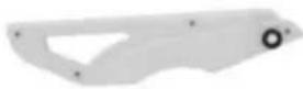
RIVING KNIFE OR SPREADER: A device that keeps the kerf of the work piece open as the material is cut. This minimizes the potential of the work piece binding against the saw blade
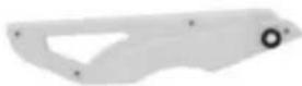
Blade Guard: Made up of 2 com- ponents: Riving Knife / Splitter, and Main Barrier Guard.
THROUGH SAWING: Any cutting operation where the blade extends through the work-piece.
WORKPIECE: The item on which the cutting operation is being performed. The surfaces of a workpiece are commonly referred to as faces, ends and edges.
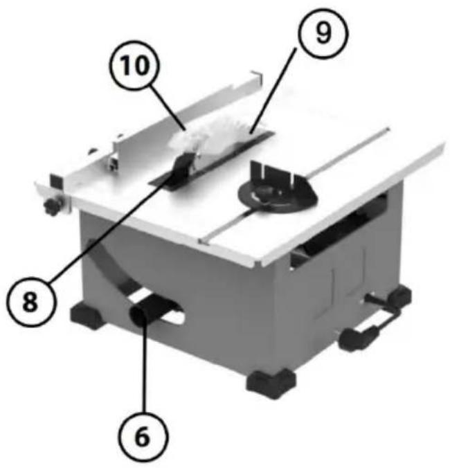
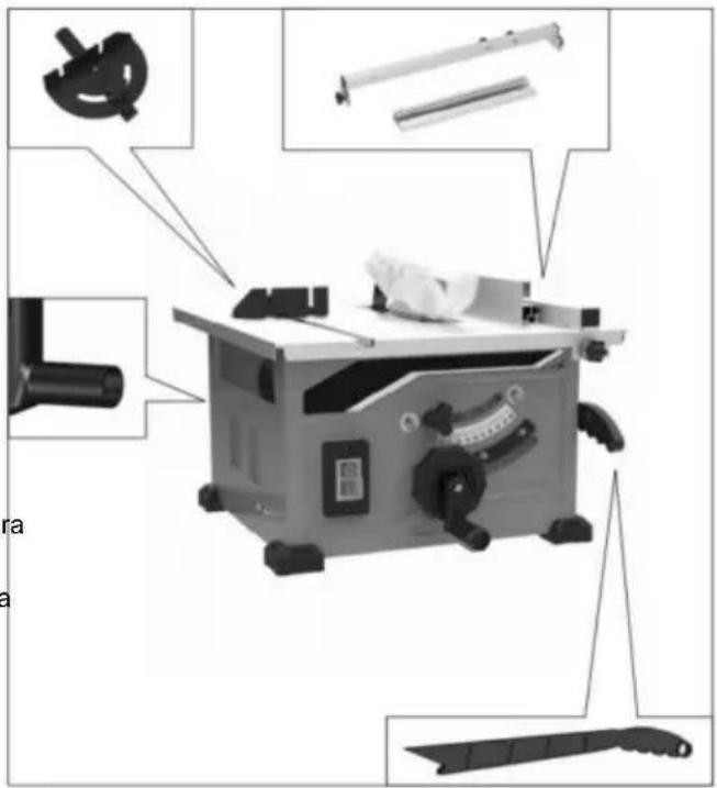
Getting To Know Your Table Saw
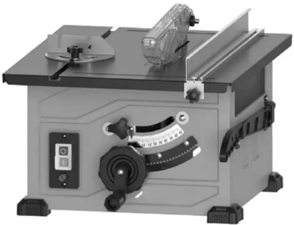
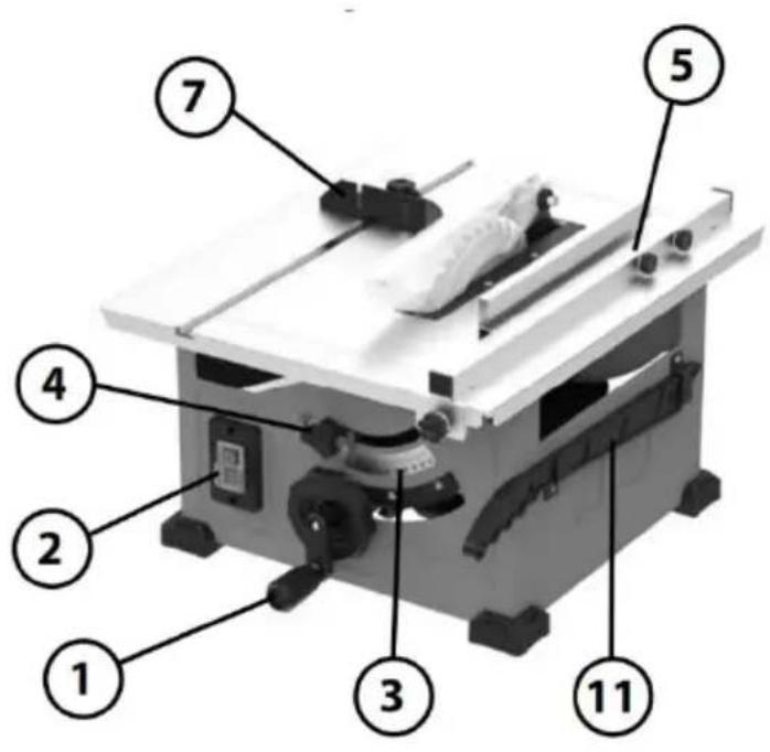
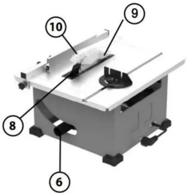
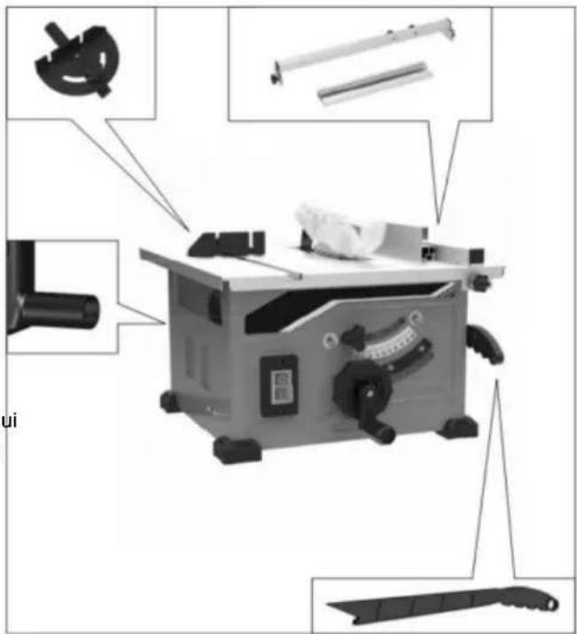
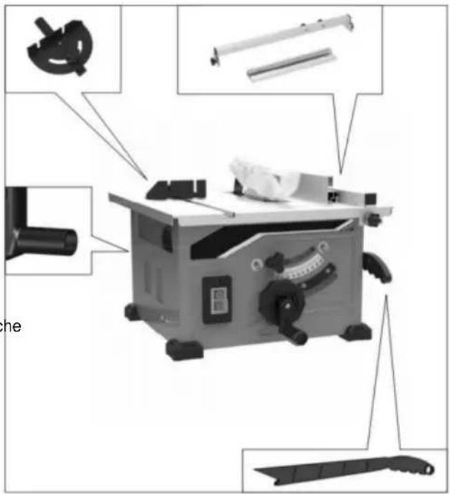
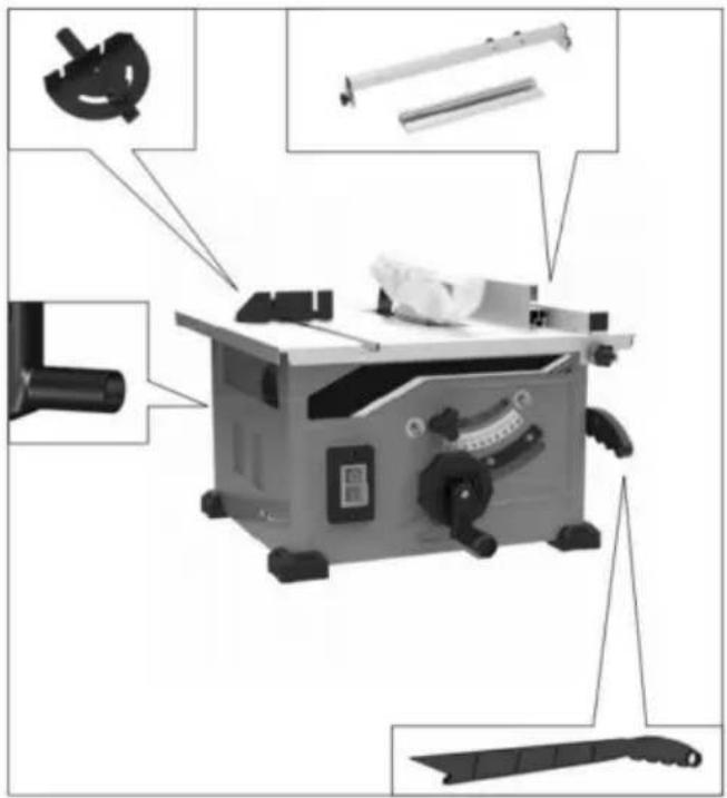
1. ELEVATION WHEEL
Elevates or lowers the blade. Also use to tilt the blade 0 to 45 degrees.
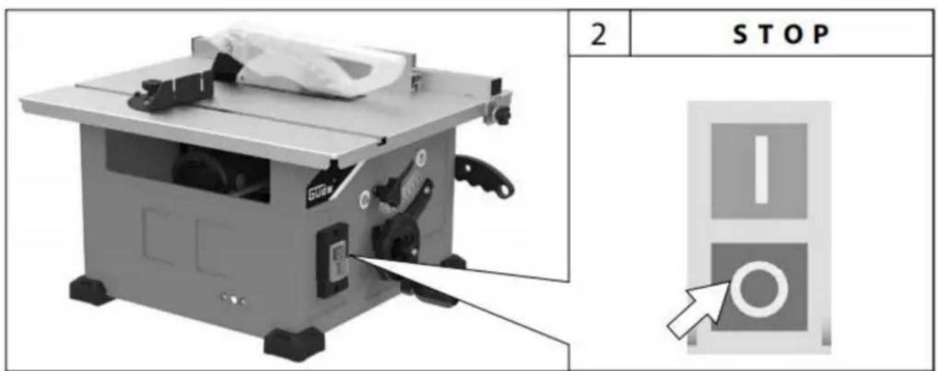
2. POWER SWITCH
Switch incorporates a hole for use with padlock to prevent accidental starting.
3. BEVEL SCALE
Display the inclination angle of the saw blade
4. BLADE BEVEL LOCK HANDLE
Locks the blade to desired bevel angle
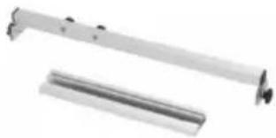
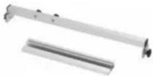
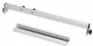
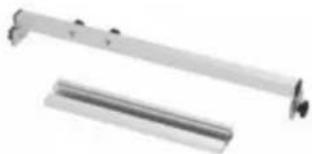
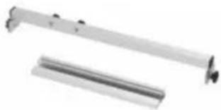
5. RIP FENCE
Securely attaches to the table with loc latches on both ends.
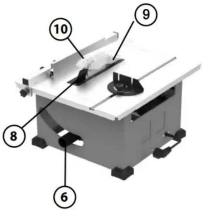
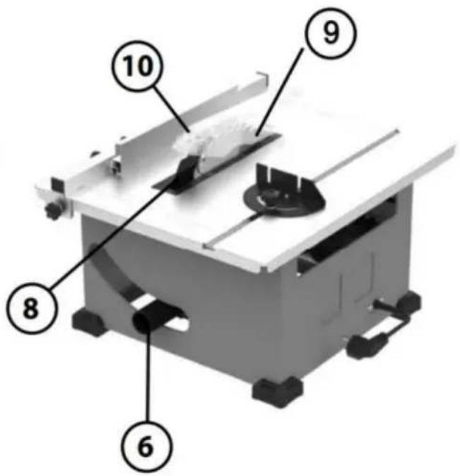
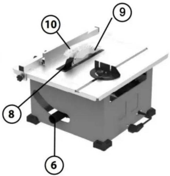
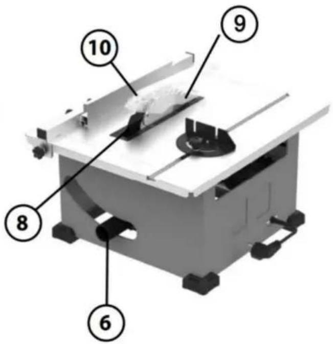
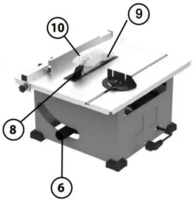
6. DUST PORT/VACUUM HOOK-UP
Removable to clear pieces of wood trapped inside.
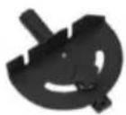
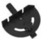
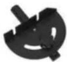
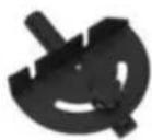
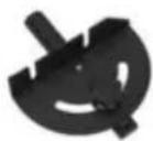
7. MITER GAUGE
Head can be locked in the desired position for crosscutting or mitering by tightening the lock knob. ALWAYS SECURELY LOCK IT WHEN IN USE.
8. RIVING KNIFE
For the riving knife to function properly, the saw blade diameter must match the appropriate riving knife.
9. SAW BLADE
210×30×2.6mm,24Z,2PCS
10. BLADE GUARD
Consists of two key elements: Riving Knife and Barrier Guard Device. Blade Guard must always be in place and working properly for all through sawing cuts.
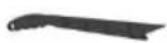
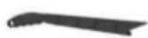
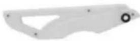
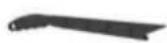
11. PUSH STICK
Use a push stick when the distance between the fence and the saw blade is less than mm.
Unpacking And Checking Contents
WARNING
To avoid injury from unex- pected starting or electrical
To avoid injury from unexpected starting orelectrical shock during unpacking and setting up, do not plug the power cord a source of power. This cord must remain unplugged when- ever you are assembling ( making adjustments to the table saw with s
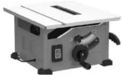
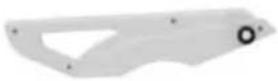
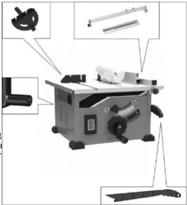
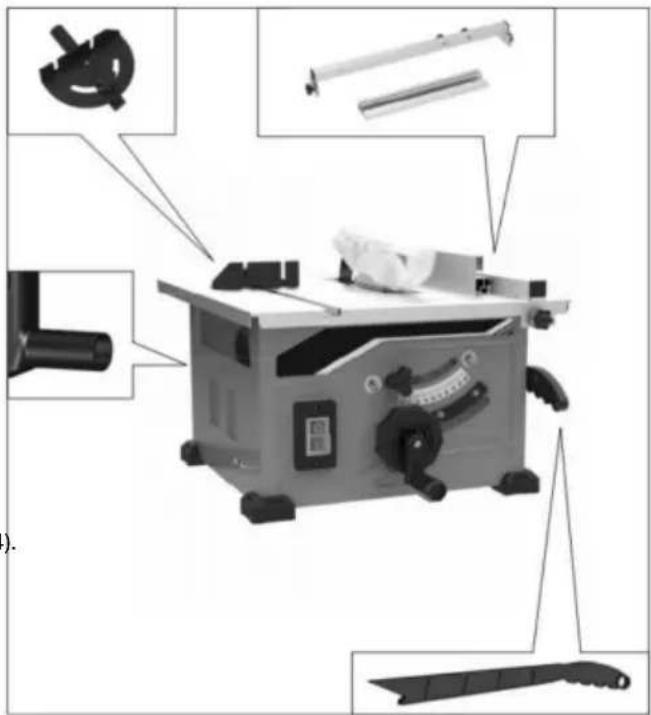
Separate all parts from the packing material and check each one with the illustration an the list of Loose Parts to make certain that items are accounted for before discarding a packing material (Fig . 3).
WARNING
If anyparts are missing, do not attempt to assemble the
table saw, plug in the power cord or tu switch on until the missing parts are ob and are installed correctly.
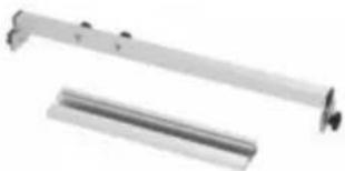
| TABLE OF LOOSE PARTS | ||
| ITEM | DESCRIPTION | QTY. |
| 1 | Table Saw | 1 |
| 2 | Blade Guard | 1 |
| 3 | RIP FENCE | 1 |
| 4 | Miter Gauge | 1 |
| 5 | Push Stick | 1 |
| 6 | Wrench(In the device) | 1 |
| 7 | Manual | 1 |
REMOVE CABLE TIE AND STYROFOAM BLOCK
(Used for shipping purpose only)
With the table surface on the ground, located cable tie that anchors the motor/blade asset to the base. Using scissors or wire cutter and remove the cable tie (Fig 4).
SCOPE OF DELIVERY
FIG.3
1
natural_image
Exterior view of a small industrial machine with handlebars and control panel (no visible text or symbols)2
4
5
3
natural_image
Two metallic mechanical components with no visible text or symbols6

FIG.4
Assembly
ATTACHING THE Blade Guard
WARNING To prevent personal injui always disconnect the plug FIG.5
from the power source before attaching or removing the Blade Guard.
ATTACHING THE GUARD ASSEMBLY
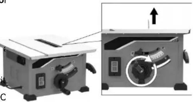
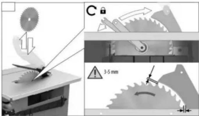
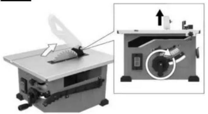
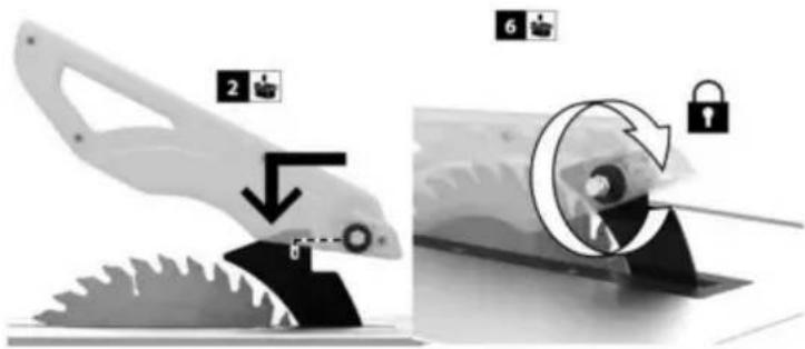
- Raise the blade as high as it will go perpendicular to table ( 0^ on bevel scale) (Fig. 5).
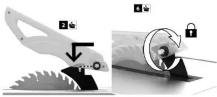
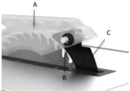
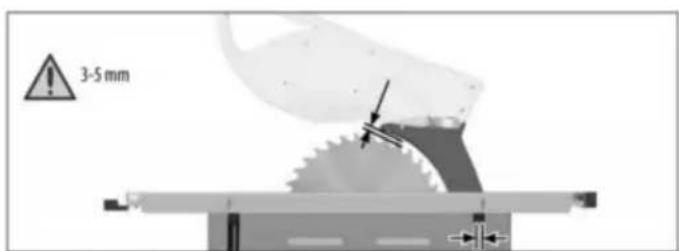
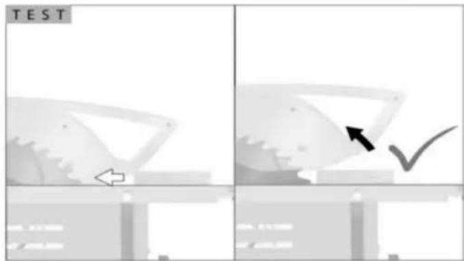
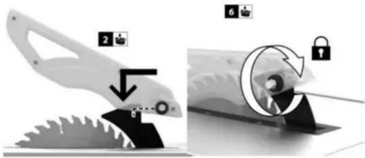
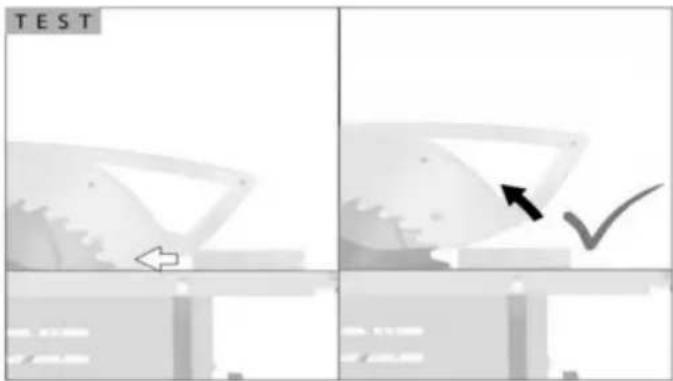
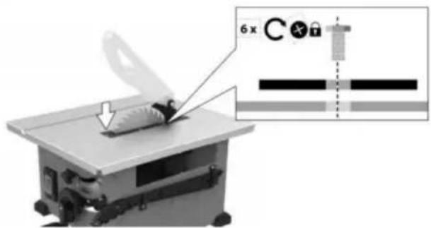
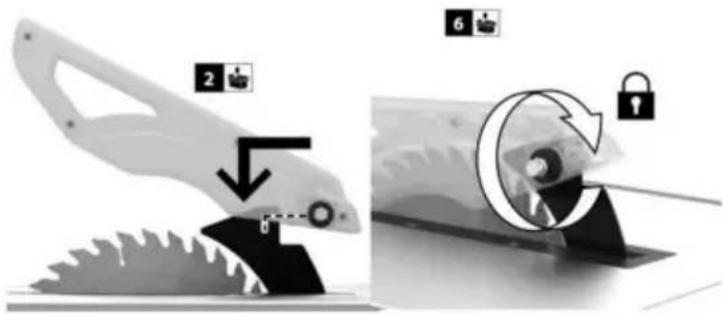
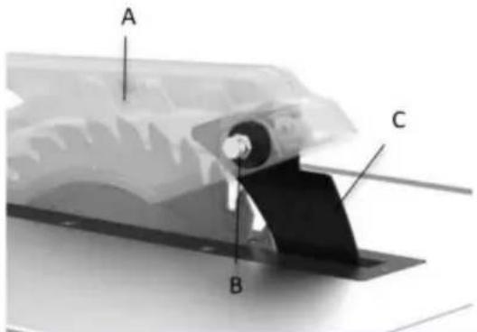
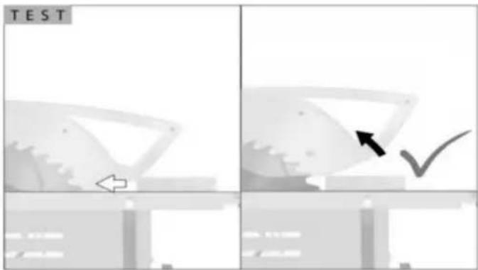
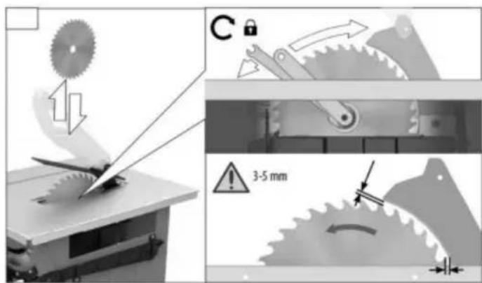
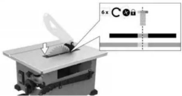
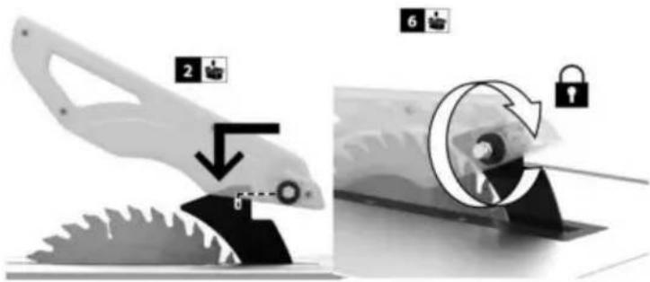
- Mount the saw blade guard together with bolt on top of the riving knife, so that the firmly seated in the slot of the riving knife.C that the guard assembly is securely connected (Fig . 6).
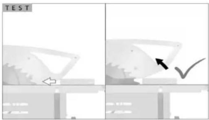
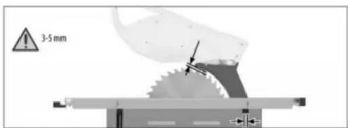
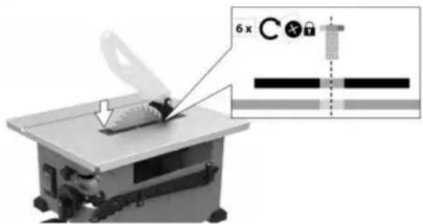
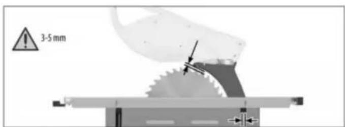
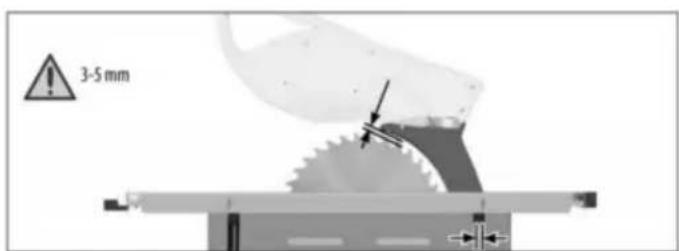
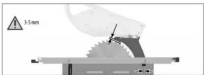
Make 3\~5mm distance between saw blade arriving knife.Do not screw in the bolt too tight saw blade guard must move freely. (Fig . 7
FIG.5
natural_image
Two views of a machine cutter shop with a gear shift and mechanical component, showing no text or symbols.FIG.6
FIG.7

Assembly
REMOVAL AND INSTALLATION OF THE BLADE
WARNING
Disconnect the plug from power source before performing any assembly, adjustment or repair avoid possible injury.
USING THE CORRECT BLADE
IMPORTANT: The saw blade provided on the tool has a diameter of 210mm. When looking a replacement blade, select one with dimensions close to the original blade. This info may not be printed on the blade's packaging is not, check the manufacturers catalog or site. VEVOR offers Premium-Qality Professional saw blades that match the requirement this tool. You must select a blade with a width of 2.6mm or more. (Fig . 10).
WARNING
To reduce the risk of injury do not use blade "damper s , "stabilizers," or "stiffening collars" on both sides of a replacement blade. These are metal plates positioned against the sides of the blade. Reduce deflection that may occur when using the saw blades. Use of these devices on both sides will prevent the blade from being properly aligned
CHANGING THE BLADE
NOTE: Clean blade of any excess oil before installation
FIG. 1
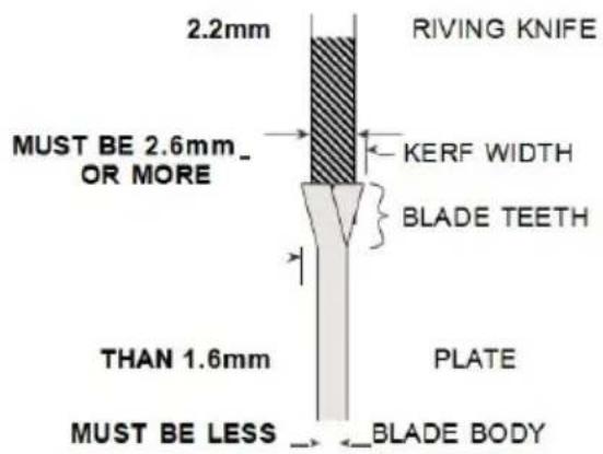
FIG.
WARNING
To reduce the risk of injury do not use extra therfsaw
blades. The kerf of the blade must be wid 2.6mm Extra thin kerf saw blades (less than 2.6mm) may cause the work piece to bind against the rising knife / splitter during cuttin is recommended that the kerf of the replacement blade used on saw be 2.6mm or more.
FIG.
WARNING
To reduce the risk of injury do not use sawblade smade
with a thick body plate. If the replacement blade's plate thickness is greater than 1.6m, the riving knife / splitter would not properly as anaid to reduce kickback. The replaceable blade's plate thickness must be less than 1
natural_image
Mechanical assembly diagram showing a cutting machine with blade, gear shift, and two wrenches (no text or labels)FIG. 1
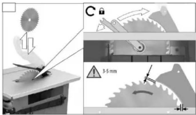
FIG. 1
-
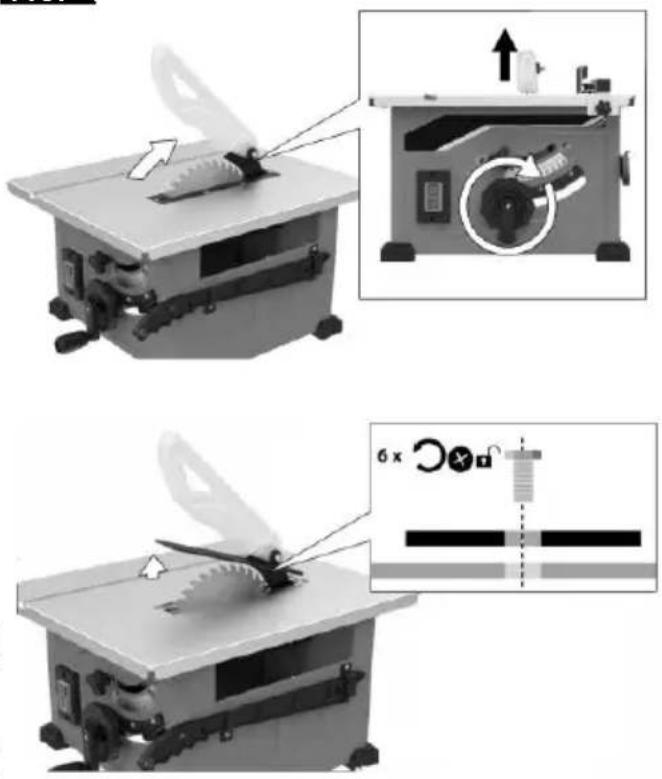
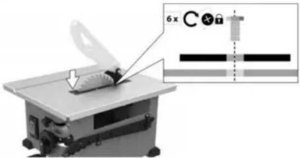
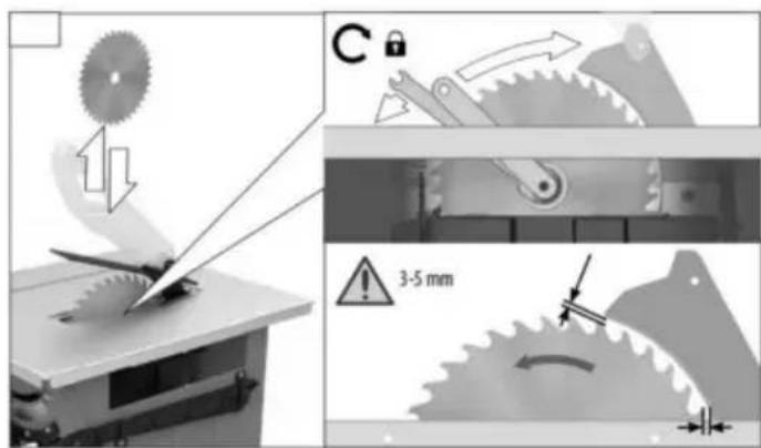
Turn elevation wheel clockwise until the up as high as it will go. (Fig .11)
-
Lose the screws, remove table insert. (Fig
-
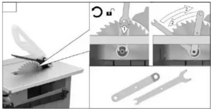
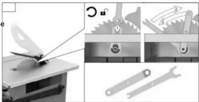
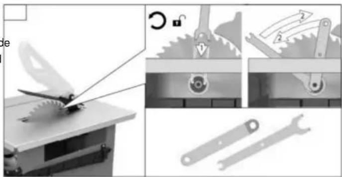
Insert the open-head hex wrench onto the shaft. While holding the first wrench, loosen arbor nut counterclockwise with the ring-head wrench.(Fig .12)
-
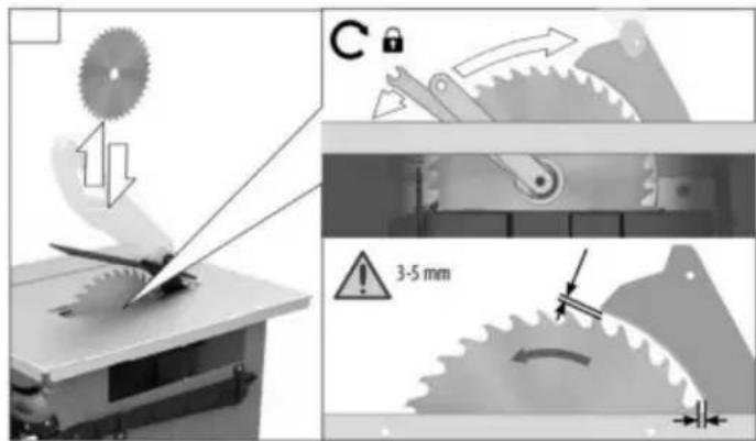
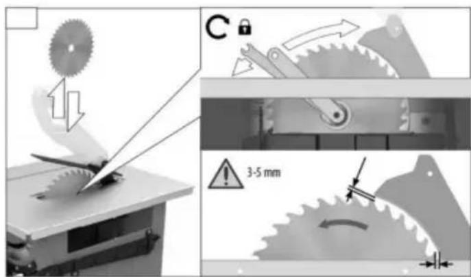
Remove the arbor nut and outer washer. blade may now be removed or installed by onto or off the arbor shaft. (Fig .13)
-
Assemble the inner washer, new blade, out washer and arbor nut as shown. (Fig .13)
making certain that the TEETH OF THE BL ARE POINTING DOWN AT THE
FRONT OF THE TABLE.
-
While holding the arbor shaft with the open hex wrench, use the ring-head hex wrench securely tighten the arbor nut clockwise. (Fig
-
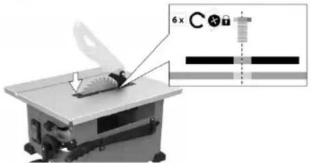
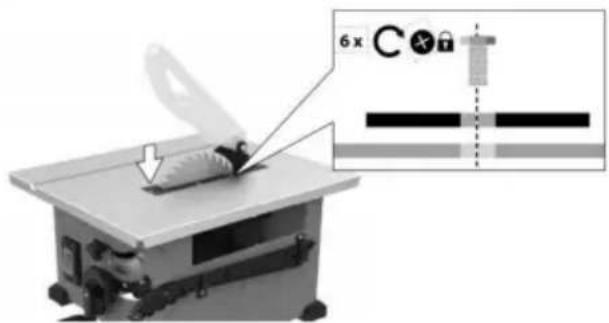
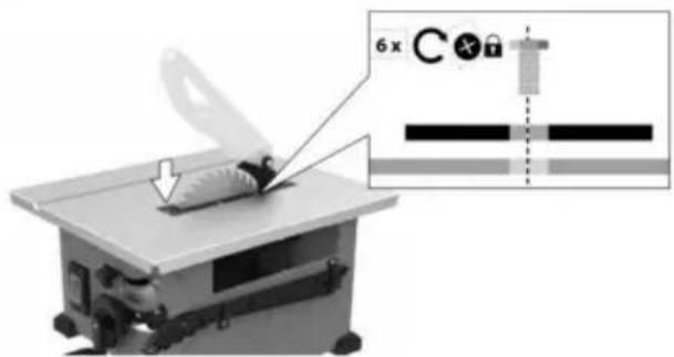
Install table insert. (Fig .14)
NOTE: The printing on different saw blades not always on the same side.
To avoid injury from a thrown workpiece, bl part, or blade contact, never operate the sa out the proper insert in place. Use the ta when sawing. Use the dado insert when i dado blade.
USING CARBIDE-TIPPED BLADES
Handle carbide-tipped blades carefully. Carbide is very brittle and can be easily damaged. Use caution when you install, use or store the blades. Do not use a carbide-tipped blade that is bent or has bent teeth, or the blade has cracks, is bro-ken, or has missing/loose carbide tips. Do not operate a carbide-tipped blade faster than its recommended speed. When selecting a blade, ensure it is rated above 5000 rpm Read, understand, and follow all warnings and instructions provided with your carbide-tipped blades.
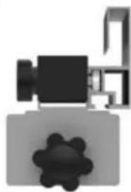
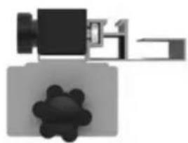
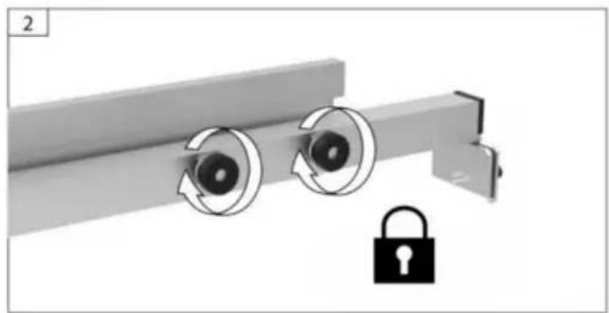
ATTACHING RIP FENCE FOR USE
-
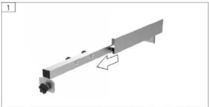
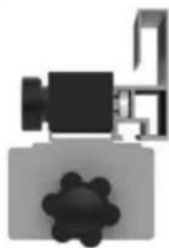
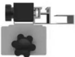
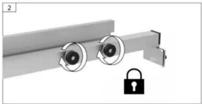
Choose the appropriate installation direction for the attached fence (A and B) and install it on the main fence.
-
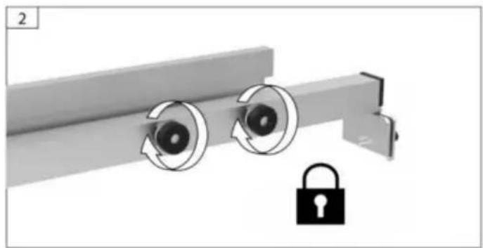
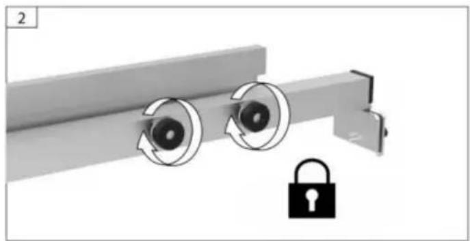
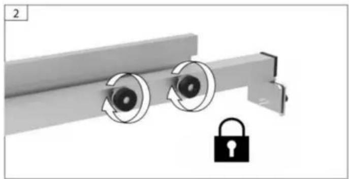
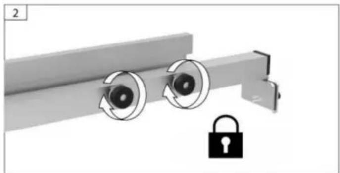
Lock the attached fence tightly. (See Fig 15)
-
Lower the fence onto the table and secure the lock levers on both sides of the fence
-
Ensure that the rail lock paddle is in the locked position prior to operating the saw
-
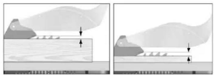
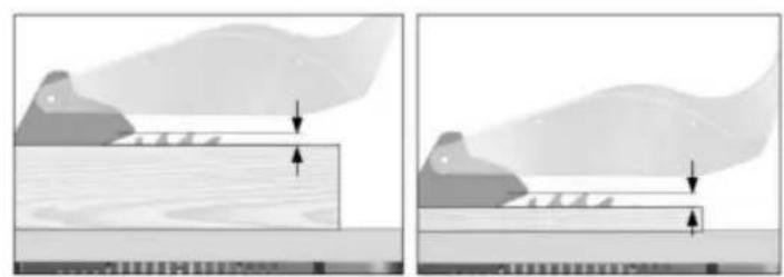
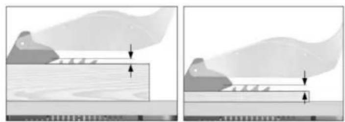
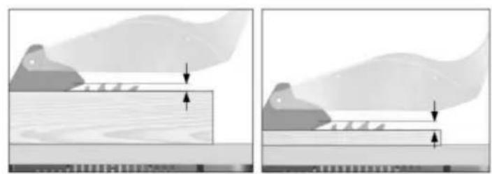
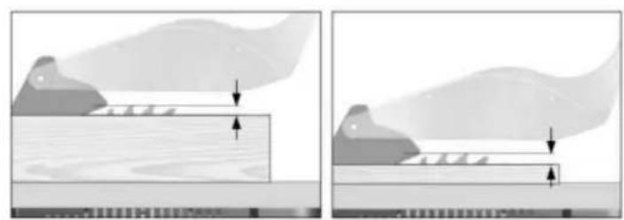
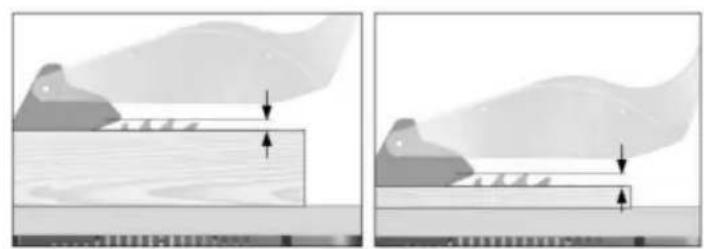
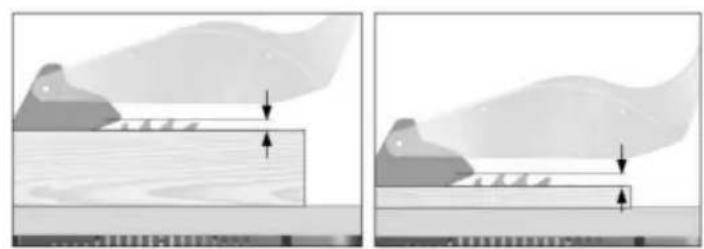
Adjust the cutting depth to the thickness of the workpiece. The sawtooth should come out of the workpiece less than a full tooth height.
FIG.
natural_image
Mechanical assembly diagram showing a lever with a bracket and pivot point, no text or symbols present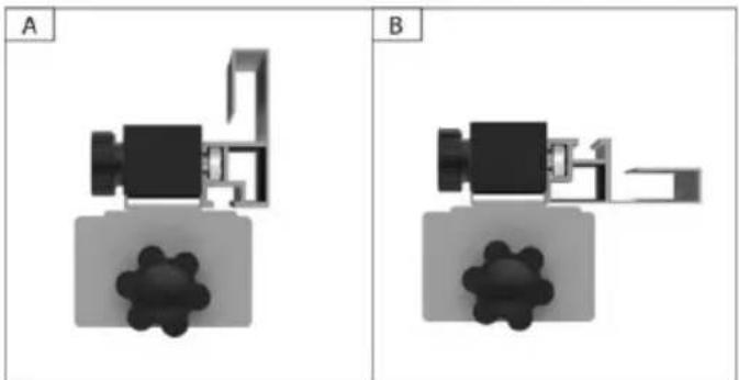
natural_image
Two identical 3D mechanical or architectural diagrams labeled A and B, showing internal components without any text or symbols.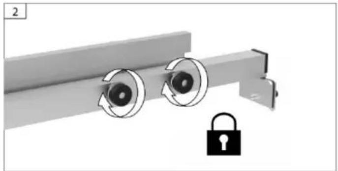
natural_image
Mechanical assembly diagram showing two rotating components with a padlock icon (no text or symbols)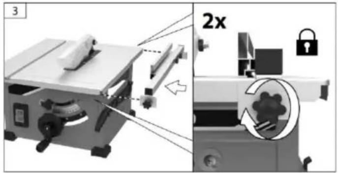
natural_image
Two diagrams showing a wooden plank under compression and a flat surface with arrows indicating force or movement (no text or symbols)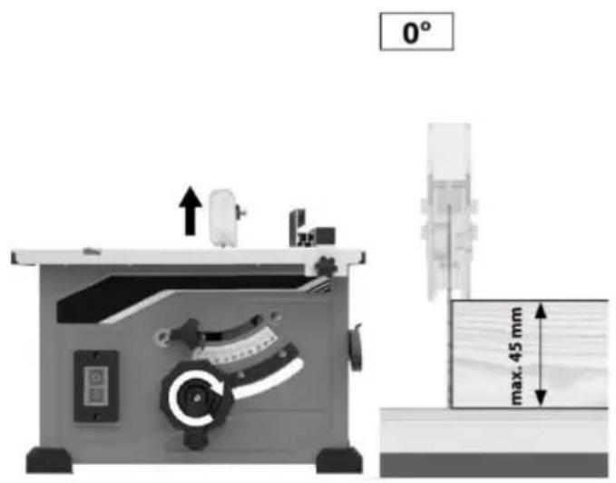
Basic Table Saw Operation
SAFETY POWER SWITCH
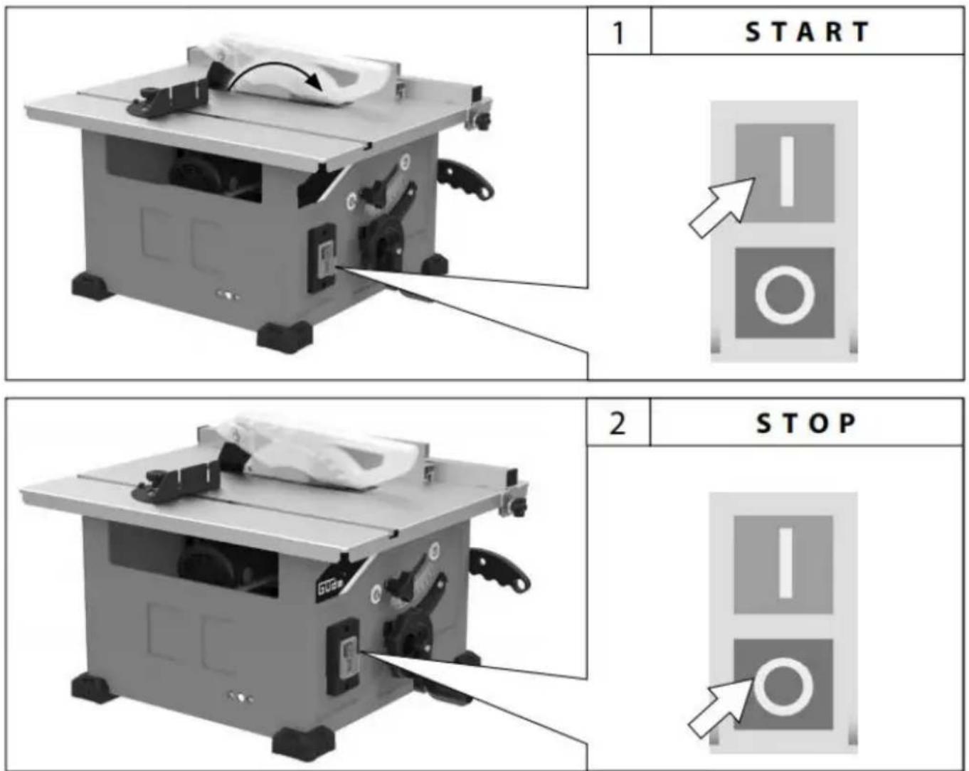
NOTE: This table saw has a safety feature that helps prevent accidental starting. When power is cut to the saw, the tool will swit the off mode. Once power is restored, the tool will need to be turned on again.
To turn saw on: Press the green button (Fig . 39) .
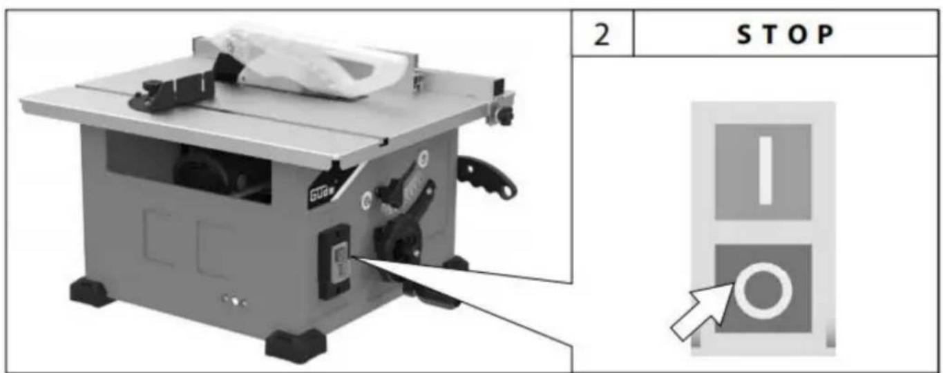
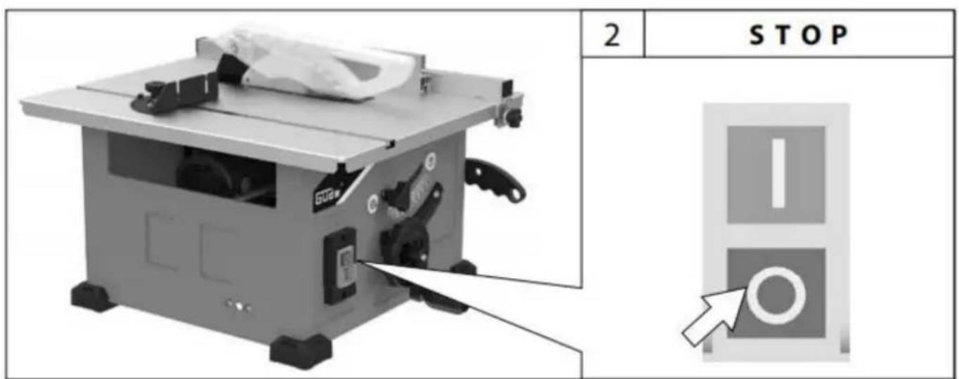
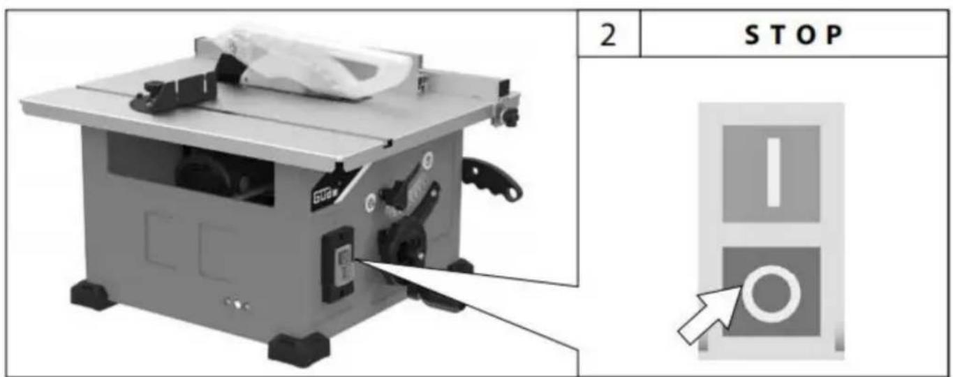
To turn saw off: Press the red paddle (which depresses the red off switch underneath) (Fig . 39) .
RESET BUTTON (POWER RESET)
This saw comes with an overload reset buttor If the saw motor overloads, a safety mechanism stops the motor automatically due to motor over-loading or low voltage.
To prevent motor overload, reduce load on motor or check voltage.
Allow motor to cool down, then press the res button and restart the saw. If the saw does not restart, wait an additional 5 minutes before restarting.
Basic Table Saw Operation
USING THE Blade Guard
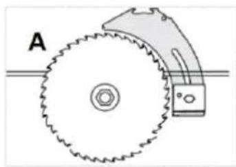
The Blade Guard has been designed for modularity, enabling the use of multiple combinations of the two main components – 1) Riving Knife / Splitter, 2) Main Barrier Guard, (Fig . 41). Any Blade Guard that need to be removed to complete a cut should be immediately reinstalled when finished. See “Attaching the Blade Guard” for detailed installation instructions. Al- way remember that the best accident prevention is the operator’s use of common sense an alertness at all times when using the table saw.
natural_image
Diagram of a mechanical gear system with labeled section A, showing toothed circular components and a rotating shaft (no text or symbols beyond label)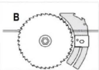
natural_image
Diagram of a gear and cam mechanism with labeled component B (no text or symbols beyond label)FIG.41
FIG.42
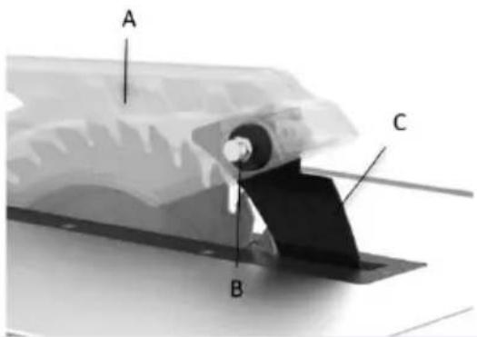
ATTACHING THE GUARD ASSEMBLY
The Blade Guard must be attached to the machines
riving knife.
Note: The machine should never be used without this guard in
its service position.
WARNING: The machine must be disconnected from the
mains supply when installing the blade guard.
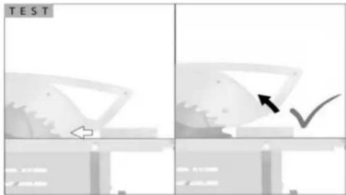
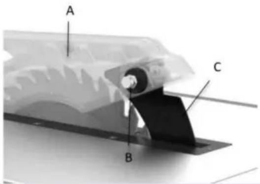
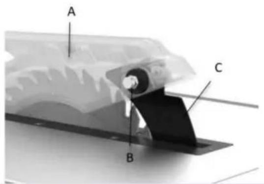
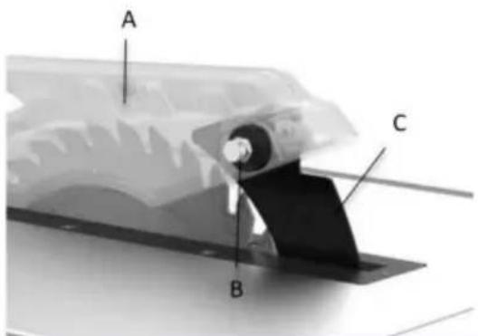
Mount the saw blade guard(A) together with the bolt(B) on top of the riving knife(C), so that the bolt is firmly seated in the slot of the riving knife(C). Check that the guard assembly is securely connected
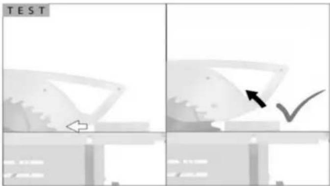
Do not screw in the bolt(B) too tightly; the saw blade guard(A) must move freely.
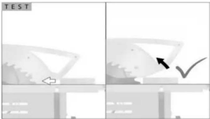
Disassembly is performed in reverse order. Caution! The saw blade guard(A) must be lowered onto the workpiece before starting the sawing operation.
Basic Table Saw Operation
BBLADE BEVEL CONTROL
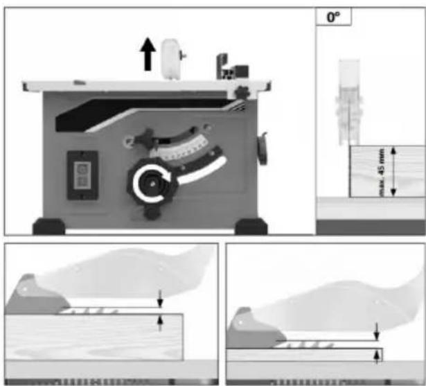
The blade height should be set higher (above) the top of the work-piece to cut.
Turn the round handle(A) to set the blade to the required depth.
- Anticlockwise: smaller cutting depth
- Clockwise: larger cutting depth.
Basic Table Saw Operation

Always wear hearing protection during cutting, and glove
when handing saw blades.
USING THE RIP FENCE
RIPPING, BEVEL RIPPING, RESAWING AND RABBETING are performed using the RIP F together with the AUXILIARY FENCE / WOF SUPPORT, PUSH STICK OR PUSH BLOCK

For your own safety, alway observe the following safety
precautions, in addition to the safety inst tions on Pages 3, 4, 5 & 6.
- Never make these cuts FREEHAND (wi 12 out using the rip fence or auxiliary devi when required), because the blade could bind in the cut and cause a KICKBACK
- Always lock the rip fence securely whe use.
- Remove miter gauge from table during operations that utilize the rip fence.
- Make sure that the blade guard is install through sawing type cuts. Replace guard IMMEDIATELY following completion resawing, rabbeting, or dadoing operation
- Have the blade extend approximately 1/above the upper surface of workpiece. tional blade exposure would increase the hazard potential.
- Do not stand directly in front of the b case of a KICKBACK. Stand to either the blade.
- Keep your hands clear of the blade ar of the path of the blade.
- If the blade stalls or stops while cuttin TURN THE SWITCH OFF before attempt to free the blade.
- Do not reach over or behind the blade pull the workpiece through the cut, to s port long or heavy workpieces, to remove small cut-off pieces of material, or FOR ANY OTHER REASON.
. Do not pick up small pieces of cut-off mrial from the table . REMOVE them by pus ing them OFF the table with a long stick Otherwise they could be thrown back at yo by the rear of the blade .
. Do not remove small pieces of cut-off material that may become TRAPPED inside the blade guard while the saw is RUNNING. THIS COULD ENDANGER YOUR HANDS or cause a KICKBACK. Turn the saw OF and disconnect the power source. After the blade has stopped turning, lift the guard are remove the piece.
. If the workpiece is warped, place the CC CAVE side DOWN . This will prevent it from rocking while it is being ripped .
Basic Table Saw Operation
RIPPING
RIPPING is known as cutting a piece of w the grain, or lengthwise. This is done usir fence. Position the fence to the desired W OF RIP and lock it in place.
Before starting to rip, be sure:
A. Rip Fence is parallel to saw blade.
B. Riving knife is properly aligned with sa
Position the wider portion of the workpiece side of the fence.
BEVEL RIPPING
Avoid bevel ripping with the fence on the side, when possible. When bevel ripping m 6" or narrower, use the fence on the right the blade ONLY. This will provide more s between the fence and the sawblade for us push stick. If the fence is mounted to the sawblade guard may interfere with proper us a push stick.
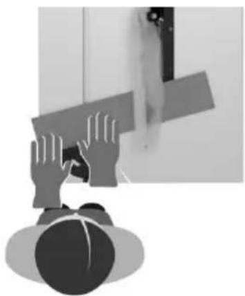
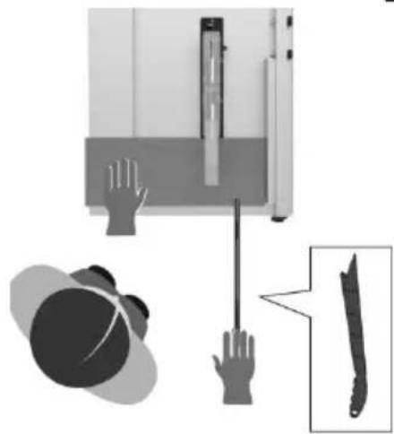
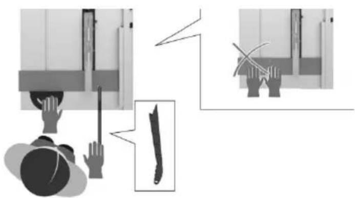
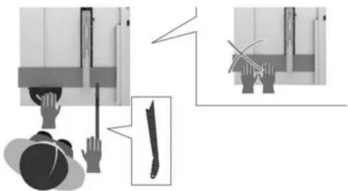
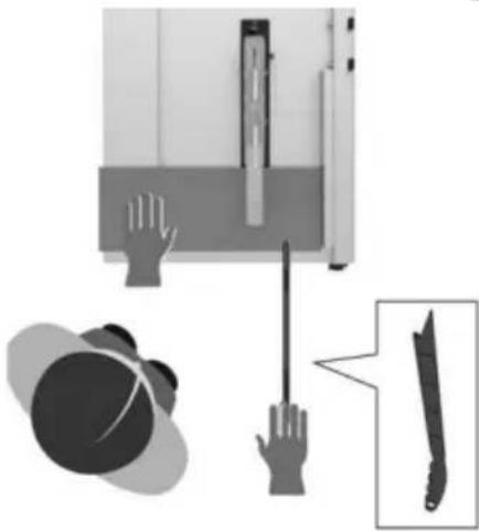
When "WIDTH OF RIP" is 6" and WIDER RIGHT hand to feed the workpiece, use LE hand ONLY to guide the workpiece, do not the workpiece with the left hand (Fig . 50)
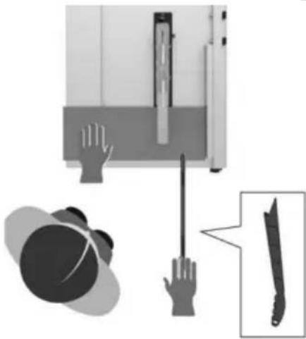
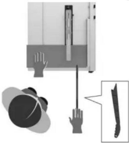
When "WIDTH OF RIP" is 2" to 6" wide L PUSH STICK to feed the work (Fig . 51)
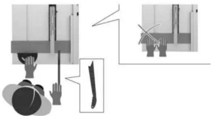
When WIDTH OF RIP is NARROWER than the push stick CANNOT be used because I guard will interfere . USE the AUXILIARY F and PUSH BLOCK .
The auxiliary fence should be used any time the "WIDTH OF RIP" is under 6 inches wide the "WIDTH OF RIP" is of a smaller dimer than the height of the workpiece, then a safety ficial auxiliary fence of adequate height to support the workpiece during the cut should be made and attached to the fence.
Feed the workpiece by hand until the end approximately . 1" from the front edge of the table . Continue to feed using the PUSH BLOCK on top of auxiliary fence UNTIL TH CUT IS COMPLETE (Fig . 52) .
FIG.50
natural_image
Illustration of hands holding a rectangular object above a person's head, with no visible text or symbols.FIG.51
natural_image
Illustration showing hands holding a device with a close-up of a knife and a hat (no text or symbols)FIG.52
Basic Table Saw Operation
NOTE: When bevel crosscutting, attach the faci so that it extends to the right of the miter gaug and use the miter gauge in the groove to the of the blade.
FIG.53
WARNING
For your own safety, alway observe the following safet
precautions, in addition to the safety inst tions in General Safety Rules, Safety Inst tions for Table Saws, and Additional Safe Rules.
Never make these cuts freehand (without use the miter gauge or other auxiliary devices) cause the blade could bind in the cut and cause a KICKBACK or cause your fingers (hand to slip into the blade.
Always lock the miter gauge securely when
Remove the rip fence from table during any erations that utilize the miter gauge.
Miter Gauge at 90° can be used from 0 to inches cross cutting.
When cross cutting with the blade set at 945° to the table, the miter gauge can be either slot on the table. When cross cutting the blade is tilted, use the slot on right side where the blade is tilted away from y hands and miter gauge.
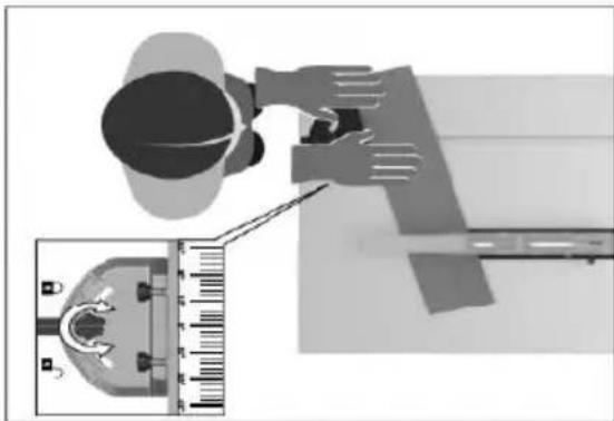
To adjust the miter angle:
Loosen lock knob and set the miter gauge that the pointer is at desired angle, then tie lock knob (Fig . 53) .
MITER GAUGE AUXILIARY FACING
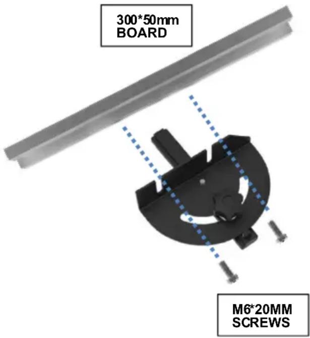
The miter gauge is designed to accept an Auxiliary Facing with pre-molded holes for fastening a suitable piece of smooth straight wood. Utilize the miter gauge as a template, attach with proper fasteners (Fig . 54) .
Example:
A. Drill 5/32" dia. holes through a board thick, 3" high, and desired length.
B. Attach with two No. 12 round head screws 1-1/2" long, not included (Fig. 54)
Be sure that the screws never protrude abc outside surface of facing.
Be sure the facing does not interfere with proper operation of the saw blade guard.
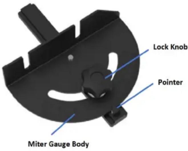
FIG.54
Basic Table Saw Operation
CROSSCUTTING
CROSSCUTTING is known as cutting wood across the grain, at 90°, or square with bo edge and the flat side of the wood. This i with the miter gauge set at 90° (Fig . 55)
Make sure that the blade guard is installed "through sawing" operations (when the sawbl cuts entirely through the thickness of the w piece). Replace guard IMMEDIATELY after plection of dading or rabbeting cuts.
Have the blade extend approximately 1/8" a top of workpiece. Additional blade exposure increase the hazard potential.
Do not stand directly in front of the blade of a THROWBACK (small cut-off piece caught the back of the blade and thrown toward tator). Stand to either side of the blade.
Keep your hands clear of the blade and or path of the blade.
If the blade stalls or stops while cutting, THE SWITCH OFF before attempting to free blade.
Do not reach over or behind the blade to workpiece through the cut, to support long heavy workpieces, to remove cut-off pieces terial, or FOR ANY OTHER REASON.
Do not pick up small pieces of cut-off mate from the table . REMOVE them by pushing OFF the table with a long stick . Otherwise could be thrown back at you by the rear blade .
Do not remove small pieces of cut-off mate are close to or may become TRAPPED ins blade guard while the saw is RUNNING . COULD ENDANGER YOUR HANDS or caus KICKBACK . Turn the saw OFF . After the has stopped turning, lift the guard and rem piece .
If the workpiece is warped, place the CONC side DOWN. This will help to prevent it fixing while it is being cut.
The graduations on the miter gauge provide racy for average woodworking . In some ca where extreme accuracy is required, when r ing angle cuts, for example, make a trial c then recheck it with an accurate square or tor .
If necessary, the miter gauge head can be sw eled slightly to compensate for any inaccuracy
TIP: The space between the miter gauge bar is the groove in the table is held to a minimum manufacturing. For maximum accuracy when using the miter gauge, always “favor” one side the groove in the table. In other words, don’t the miter gauge from side to side while cutting keep one side of the bar riding against one s the groove.
TIP: Glue a piece of sandpaper to the face o miter gauge head. This will help prevent the piece from "creeping" while it is being cut.
The miter gauge may be used in either of thegrooves in the table . Make sure it is locked
When using the miter gauge in the LEFT hand groove, hold the workpiece firmly against gauge head with your left hand, and grip the lock kn with your right hand .
When using the RIGHT hand groove, hold theworkpiece with your right hand and the lock krwith your left hand .

natural_image
Illustration of a person using a tool to lift a wall-mounted device, with an inset showing a knife (no text or symbols present)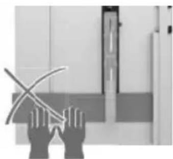
natural_image
Illustration of two hands holding a curved object, possibly a tool or device, with no visible text or symbols.Basic Table Saw Operation
REPETITIVE CUTTING
Never use the rip fence length stop, because the c and bind between the fence a kickback.
- When making repetitive cuts, clamp a length of wood 3" long to the table at the desk length to act as a length stop.
When using the miter gauge in the LEFT hand groove, hold the workpiece firmly against the miter gauge head with your left hand, and grip lock knob with your right hand.
When using the RIGHT hand groove, hold the workpiece with your right hand and the lock kr with your left hand.
FIG. 5

When clamping the block, make sure that the end
the block is well in front of the sawblad sure that it is clamped securely.
-
Slide the workpiece along the miter gate until it touches the block, then hold it securely.
-
Make the cut, pull the workpiece back, push the cut-off piece off the table with push stick. DO NOT ATTEMPT TO PIC UP AS THIS COULD ENDANGER YOUR HANDS.
natural_image
Top-down view of a person adjusting a mechanical component with an inset close-up showing a tool (no text or symbols visible)BEVEL CROSSCUTTING
MITER CUTTING
MITER CUTTING is cutting wood at an angle other than 90° with the edge of the wood the same procedure as you would for cross (Fig . 56) .
Adjust the miter gauge to the desired angle lock it.
The miter gauge may be used in either of the grooves in the table.
BEVEL CROSSCUTTING is the same as cross-cutting except that the wood is also cut at a angle other than 90^ with the flat side of the (Fig. 57).
Adjust the blade to the desired angle .
Use the Miter Gauge in the groove to the RIC or the LEFT of the blade.

COMPOUND MITER CUTTING
COMPOUND MITER CUTTING is a combination of miter cutting and bevel crosscutting. The cut is made at an angle other than 90° to be the edge and the flat side of the wood.
Adjust the miter gauge and the blade to the desired angle and make sure that miter gauge is locked.
Maintaining Your Table Saw
LUBRICATION
The gear case has been completely lubricated at the factory. However, after six months to one year, depending upon use, it's wise to return your tool to the nearest Service Center for the following:
- Brushes replaced .
- Parts cleaned and inspected .
- Relubricated with fresh lubricant.
• Electrical system tested. - All repairs .
The following parts should be oiled occasionally with SAE No . 20 or No . 30 WD 40 (Fig . 67) .
- Elevation, support rods, and gears.
- Sliding rails and supports.
- Table locking cams (Front & Rear)
Maintaining Your Table Saw
Danger!
Always pull out the mains power plug before starting any cleaning work.
1. Cleaning
- Keep all safety devices, air vents and the motor housing free of dirt and dust as far as possible. Wipe the equipment with a cle cloth or blow it with compressed air at low pressure.
• We recommend that you clean the device immediately each time you have finished using it. - Clean the equipment regularly with a mo cloth and some soft soap. Do not use cleaning agents or solvents; these could attack the plastic parts of the equipment.
Ensure that no water can seep into the de The ingress of water into an electric tool increases the risk of an electric shock
2. Carbon brushes
In case of excessive sparking, have the carbon brushes checked only by a qualified electrician.
Danger! The carbon brushes should not be replaced by anyone but a qualified electrician.
3. Maintenance
There are no parts inside the equipment which require additional maintenance.
4. Ordering replacement parts:
Please quote the following data when ordering replacement parts:
- Type of machine
• Article number of the machine
• Identification number of the machine - Replacement part number of the part required
Troubleshooting
WARNING
Turnswitch“OFF”andalwaysremoveplugfromthepowersourcebeforetroubleshootir
| PROBLEM | CAUSE | SOLUTION |
| Saw willnotstart | Powercordisnot plugged in. | Plugsawin. |
| Fuseor circuit breaker tripped. | Replacefuse orresettripped circuitbreaker. | |
| Corddamaged. | HavecordreplacedbyanAuthorizedVEVOR ServiceCenterorServiceStation. | |
| Burnedoutswitch. | HaveswitchreplacedbyanAuthorizedVEVOR ServiceCenterorServiceStation. | |
| Bladedoesnotcomeptospeed | Extensioncordtoolightortoolong. | Replace withadequatecord. |
| Lowsupply voltage. | Contact yourelectriccompany. | |
| Excessive vibration | Failuretotighten bevellockhandle | See“GettingToKnowYourTableSaw”section. |
| Bladeoutofbalance. | DiscardBladeandusedifferentblade. | |
| Sawnotmountedsecurelytostand or workbench. | Tightenallmounting hardware,See“Mounting the TableSaw” section. | |
| ArborNutnot tight. | See“Assembly” section, “ChangingTheBlac | |
| Cutbinds,burns,stal motor whenripping | Dullblade with improper tooths | Sharpenorreplaceblade. |
| Warpedboard. | Makesureconcaveorhollowsideisfacing “DOWN” and feedslowly. | |
| Ripfencenot paralleltoblade. | See “Adjustments” section“Aligning RipFence.” | |
| Rivingknifeoutofalignment. | See “Adjustments” section, “Riving knife alignment.” | |
| Cutnottrueat90° or45°positions | Alignmentscrewsnot adjusted properly. | See“Adjustments” section,“AdjustingBlade Parallel toMiterGauge Slots.” |
| Plasticmeltsorblade tipsoverheatwhen cutting | Feedrate tohigh. | Slow feedratethroughblade. |
| Blades tipnotsharp | Sharpenorreplaceblade | |
| Tiltlockhandle elevation wheel hard tomove | Bevellockhandlenotloosenedwher making tilt adjustment. | See“GettingToKnowYourTableSaw”section, “Blade Tilt Lock Knob.” |
| Sawdustondepthscrew threads. | See“Maintaining YourTableSaw” section, “Lubrication.” | |
| CircuitBreaker Trip | Circuit breaker trips repeatedly while cutting. | Replacethe bladewith a new blade. Red force applied to workpiece during cutting |
TECHNICAL DATA
AC Motor 230-240V \~ 50Hz
Power 1200W
Cutting-Off Wheel 0210x030x2.6mm
Idle Speed n0 4800RPM
Number Of Teeth 24
Cutting Height Max. 45 mm / 90°.
27 mm / 45°
Tilting Saw Blade ....infinite 0 - 45°
Extractor Socket 0 35 mm
Weight approx. 13.0kg
Operating mode S6 40%: Continuous operation with idling (cycle time 10 minutes).
To ensure that the motor does not become excessively hot, it may only be operated for 40% of the cycle at the specified rating and must then be allowed to idle for 60% of the cycle.
Danger!
Sound and vibration
Sound and vibration values were measured in accordance with EN 62841.
LpA sound pressure level 92,4dB(A)
KpA uncertainty 3 dB
LWA sound power level 105,4 dB(A)
KWA uncertainty 3 dB
The quoted values are emission values and not necessarily reliable workplace values.
Although there is a correlation between emission and immission levels it is impossible to d certain conclusions as to the need for additional precautions.
Factors with a potential influence on the actual immission level at the workplace include the duration of impact, the type of room, and other sources of noise, etc., e.g. the number of machines and other neighboring operations. Reliable workplace values may also vary from country to country. With this information, the user should at least be able to make a better assessment of the dangers and risks involved.
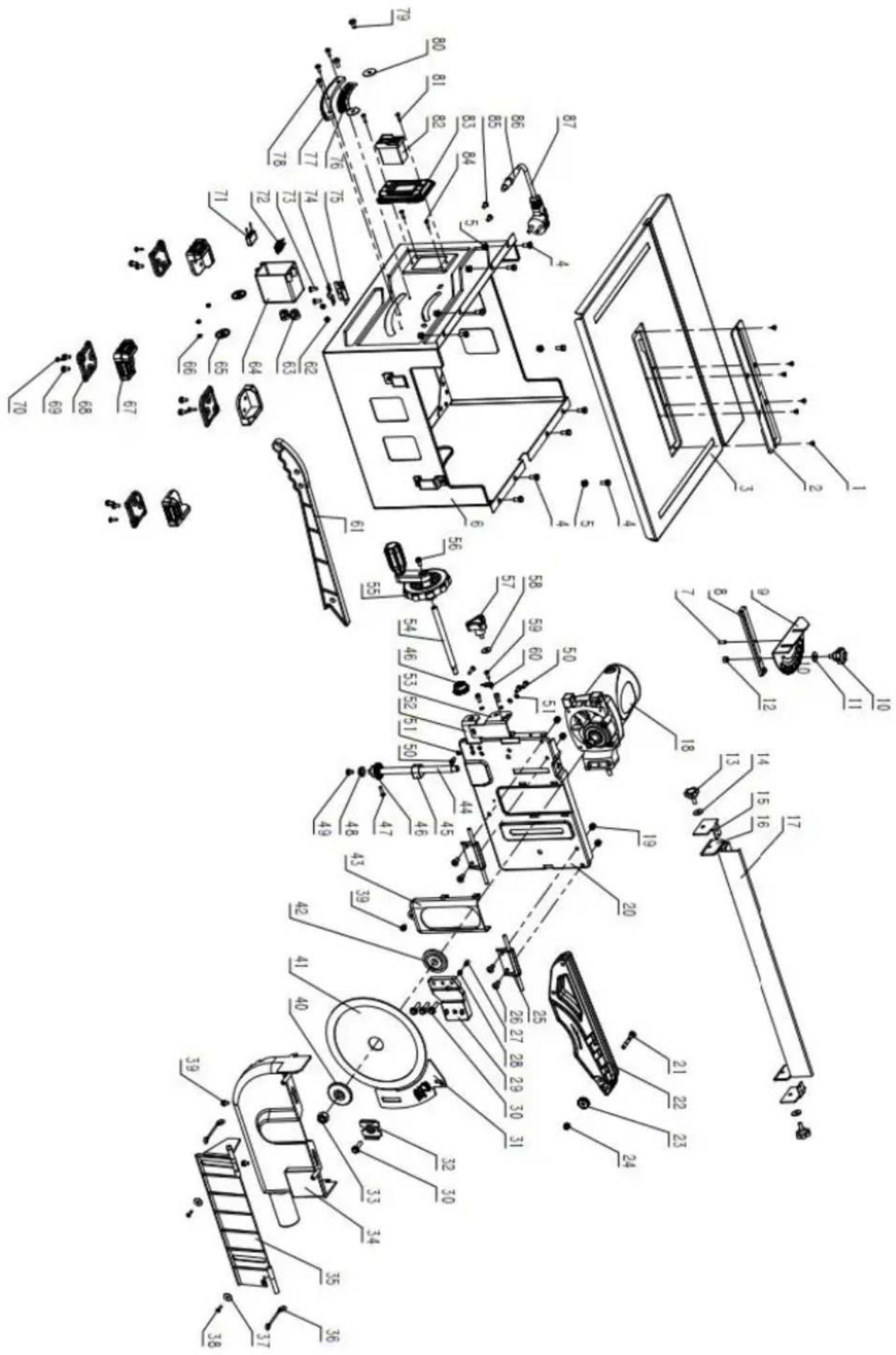
| No. | Name | Qty. | No. | Name | Qty. |
| 1 | Countersunk screw | 6 | 45 | Stop nut | 1 |
| 2 | Plastic knife groove | 1 | 46 | Bevel gear | 2 |
| 3 | Worktable | 1 | 47 | Self tapping screws | 2 |
| 4 | External hexagonal screw | 10 | 48 | Screw spacer sleeve | 1 |
| 5 | Self-locking nut | 10 | 49 | Cross triple combination screw | 1 |
| 6 | Box body | 1 | 50 | Internal hexagonal screw | 5 |
| 7 | Cylindrical pin | 1 | 51 | Elastic pad | 5 |
| 8 | Guide block | 1 | 52 | Handwheel shaft support plate | 1 |
| 9 | Dial | 1 | 53 | U-shaped plate | 1 |
| 10 | Handlebar | 1 | 54 | Handwheel shaft | 1 |
| 11 | Flat cushion | 1 | 55 | Handle assembly | 1 |
| 12 | Nut | 1 | 56 | Cross triple combination screw | 1 |
| 13 | Handlebar | 2 | 57 | Handlebar | 1 |
| 14 | Flat cushion | 2 | 58 | Flat cushion | 1 |
| 15 | Fixed clip | 2 | 59 | Cross screw | 1 |
| 16 | Activity clip | 2 | 60 | Pointer | 1 |
| 17 | Guide ruler | 1 | 61 | Push rod | 1 |
| 18 | Motor assembly | 1 | 62 | Nut | 2 |
| 19 | Self locking nut M6 | 4 | 63 | Crimping card | 2 |
| 20 | Motor fixing plate | 1 | 64 | Switch box cover | 1 |
| 21 | Non standard carriage with upper cover | 1 | 65 | Stop sleeve | 2 |
| 22 | Upper cover | 1 | 66 | Nut | 3 |
| 23 | Handlebar | 1 | 67 | New Footing | 4 |
| 24 | Self locking nut M6 | 1 | 68 | New Footing - Rubber | 4 |
| 25 | U-shaped plate components | 2 | 69 | Cross triple combination screw | 8 |
| 26 | Cross screw | 4 | 70 | Self tapping screws | 4 |
| 27 | Brake column | 1 | 71 | capacitance | 1 |
| 28 | Brake spring | 1 | 72 | inductance | 1 |
| 29 | Distributor bottom plate | 1 | 73 | Cross screw | 2 |
| 30 | External hexagonal flange edge screw | 4 | 74 | Bridge | 1 |
| 31 | Splitter | 1 | 75 | Great right angle | 1 |
| 32 | Splitter pressure plate | 1 | 76 | Angle label | 1 |
| 33 | Nut | 1 | 77 | rack | 1 |
| 34 | Lower cover | 1 | 78 | Cross two combination screw | 3 |
| 35 | Rotating baffle | 1 | 79 | Cross screw | 2 |
| 36 | Baffle seat | 2 | 80 | Flat cushion | 2 |
| 37 | Widened flat cushion φ five | 2 | 81 | Self tapping screws | 2 |
| 38 | Self tapping screws | 2 | 82 | switch | 1 |
| 39 | Cross triple combination screw | 3 | 83 | Switch panel | 1 |
| 40 | External Card Disk | 1 | 84 | Self tapping screws | 2 |
| 41 | Saw blade | 1 | 85 | Cross screw | 2 |
| 42 | Internal chuck | 1 | 86 | Hose B appears | 1 |
| 43 | Saw blade guard board | 1 | 87 | Power cord+plug | 1 |
| 44 | Lead screw | 1 | |||
VEVOR®
TOUGH TOOLS, HALF PRICE
Technical Support and E-Warranty Certificate www.vevor.com/support
VEVOR®
TOUGH TOOLS, HALF PRICE
natural_image
Industrial machine with workpiece and control panel (no visible text or symbols)BESOIN D'AIDE ? CONTACTEZ-NOUS!
natural_image
Icon of a person wearing glasses inside a circle (no text or symbols)
natural_image
Exterior view of a small metal workbench with visible blades and control knobs (no text or symbols)2
4
5

3
natural_image
Two metallic mechanical components with cylindrical bases, no visible text or symbols6

FIG.4
Assemblée
FIXATION DU PROTÈGE-LAME
AVERTISSEMENT
Assemblée
RETRAIT ET INSTALLATION DE LA LAME

AVERTISSEMENT
natural_image
Mechanical assembly diagram showing a saw cutting machine with three views of the tool (no text or labels present)FIGUE. 13
FIGUE. 14
natural_image
Mechanical assembly diagram showing a beam with mounting holes and a directional arrow (no text or symbols)A
natural_image
Abstract 3D rendering of a camera and a gear-like object (no text or symbols)B
natural_image
Pure electrical circuit lines without any symbolsMachine Translated by Google
natural_image
Diagram showing a mechanical lever mechanism with rotating circular components and a padlock icon (no text or symbols)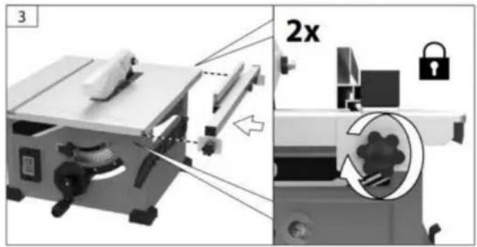
natural_image
Two grayscale diagrams showing a wooden plank under load with arrows indicating force or movement, no text or symbols present.
natural_image
Diagram of a saw cutting tool with labeled section A, showing blade and gear components (no text or symbols beyond label)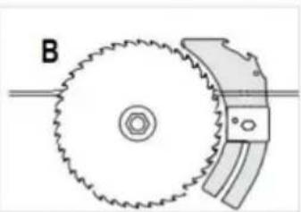
natural_image
Diagram of a gear and blade assembly with labeled component B (no text or symbols beyond label)FIG.41
FIG.42
FIXATION DE L'ENSEMBLE DE PROTECTION
natural_image
Illustration of hands cleaning a wall with a tool, no text or symbols presentFIG.51
DÉCHIRURE EN BISEAUX
natural_image
Illustration showing hands holding a tool and a knife, with a magnified inset of the knife (no text or symbols)FIG.52
natural_image
Illustration of a person using a tool to lift a wall-mounted device, with an inset showing a blade being cut (no text or symbols)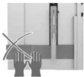
natural_image
Silhouette of two hands holding a curved object, possibly a tool or device, against a plain background (no text or symbols visible)natural_image
Top-down diagram of a person holding a device with an inset close-up showing a mechanical component (no text or symbols)COUPE TRANSVERSALE EN BISEAUX
Poids .... env. 13,0 kg
Machine Translated by Google
natural_image
Industrial machine with workpiece and control panel (no visible text or symbols)Standards Association
natural_image
Icon of a person wearing glasses inside a circle (no text or symbols)
natural_image
Exterior view of a small metal workbench with visible blades and control knobs (no text or symbols)natural_image
Two metallic mechanical components with cylindrical bases, no visible text or symbols5
6

Abb.4
KABELBINDER UND
STYROPORBLOCK ENTFERNEN
Montage
Montage
ENTFERNEN UND INSTALLIEREN DER KLINGE
Trennen Sie vor der
Abb.11
natural_image
Mechanical device with a cutting tool and internal components, shown from two different angles (no text or symbols visible)
Um das Risiko von
In ju R
natural_image
Mechanical assembly diagram showing a saw cutting machine with three different tools (no text or labels visible)Abb. 13
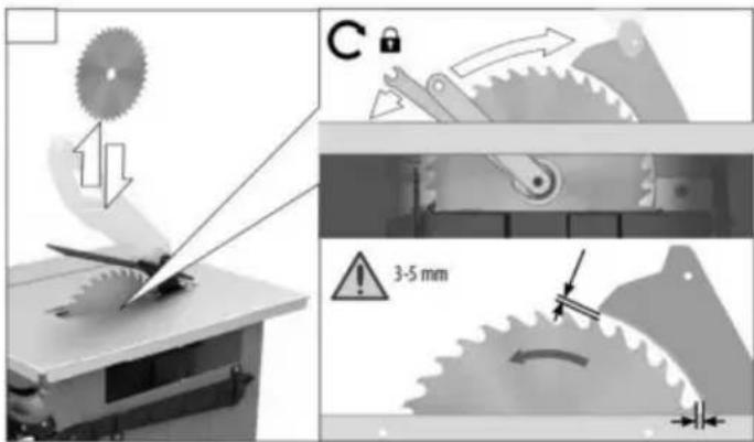
Abb. 14
natural_image
Mechanical assembly diagram showing a beam with mounting holes and a directional arrow (no text or symbols)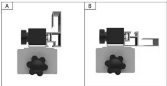
natural_image
Two identical mechanical or architectural diagrams labeled A and B, each showing a component with a gear-like base (no text or symbols present)Machine Translated by Google
natural_image
Mechanical assembly diagram showing two rotating components with a padlock icon (no text or symbols)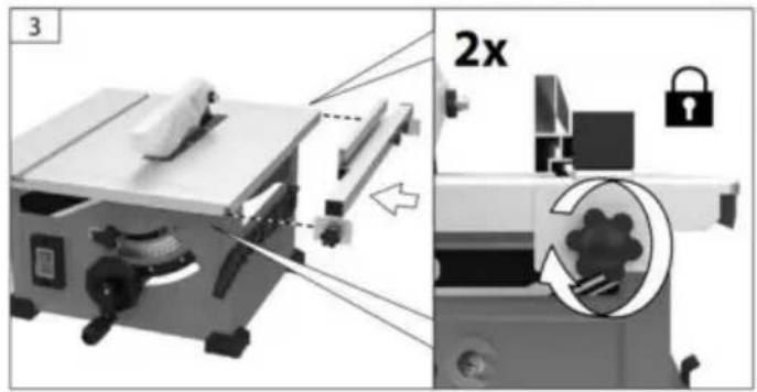
natural_image
Two grayscale diagrams showing a wooden plank under load with arrows indicating force or movement, no text or symbols present.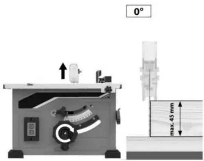
natural_image
Two mechanical diagrams labeled A and B showing gear meshing with no visible text or symbols.Abb.41
Abb.42
natural_image
Illustration of hands cleaning a wall with a tool, no text or symbols presentAbb. 51
natural_image
Illustration showing a hand holding a tool above a device, with a close-up of a knife and a hat nearby (no text or symbols)Abb. 52
natural_image
Illustration of a person using a tool to lift a wall-mounted device, with an inset showing a blade being cut (no text or symbols)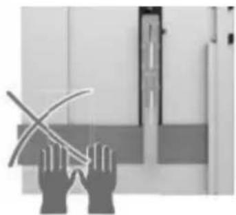
natural_image
Silhouette of two hands holding a curved object, possibly a tool or device, against a plain background (no text or symbols visible)natural_image
Top-down diagram of a mechanical device with a cylindrical component and a close-up inset showing internal components (no text or symbols)FASENKREISSCHNITT
Machine Translated by Google
natural_image
Industrial machine with workpiece and control panel (no visible text or symbols)Laboratories e la Canadian
Standards Association
natural_image
Icon of a person wearing glasses inside a circle (no text or symbols)
natural_image
Exterior view of a small metal workbench with visible blades and control knobs (no text or symbols)2
4
5
3
natural_image
Two metallic mechanical components with cylindrical bases, no visible text or symbols6

FIGURA 4
Assemblea
natural_image
Two views of a machine cutter shop with internal components, showing external and internal assembly (no text or symbols visible)FIG.7
FIGURA 6
Assemblea

natural_image
Mechanical assembly diagram showing a saw cutting machine with three views of the blade and two wrenches (no text or labels)FICO. 13
FICO. 14
natural_image
Mechanical assembly diagram showing a beam with mounting holes and a directional arrow (no text or symbols)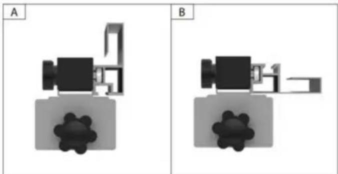
natural_image
Two identical mechanical or architectural diagrams labeled A and B, each showing a component with a gear-like base (no text or symbols present)Machine Translated by Google
natural_image
Mechanical assembly diagram showing two rotating components with a padlock icon (no text or symbols)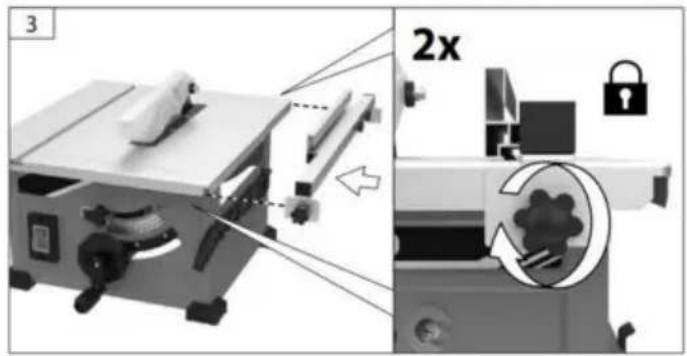
natural_image
Two grayscale diagrams showing a wooden plank under load with arrows indicating force or movement, no text or symbols present.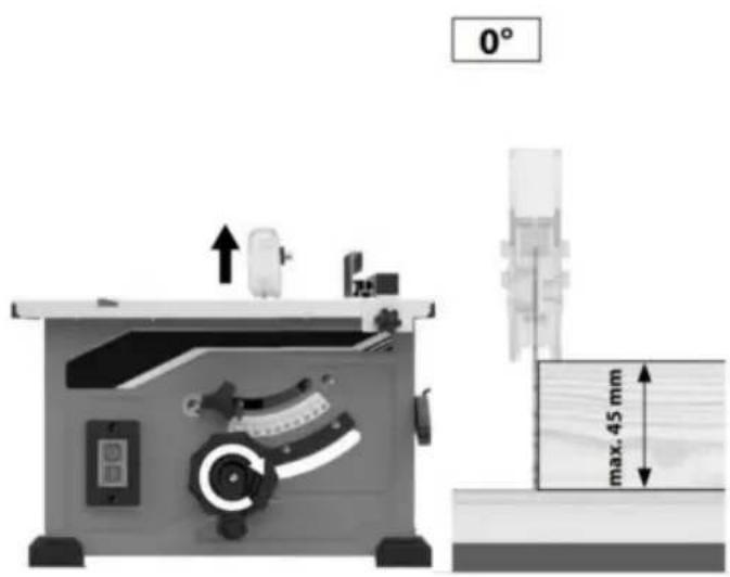
natural_image
Two mechanical diagrams labeled A and B showing gear meshing with no visible text or symbols.FIGURA 41
FIGURA 42
natural_image
Illustration of hands cleaning a wall with a tool, no text or symbols presentFIGURA 51
natural_image
Illustration showing hands holding a tool and a knife, with a magnified inset of the knife (no text or symbols)FIG.52
M6*20MM VITI
natural_image
Illustration of hands cleaning a wall with a knife, showing a close-up of the blade (no text or symbols)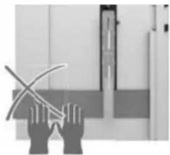
natural_image
Silhouette of two hands holding a curved object, possibly a tool or device, against a plain background (no text or symbols visible)natural_image
Top-down view of a mechanical assembly with a close-up inset showing internal components (no text or symbols visible)Machine Translated by Google
natural_image
Industrial machine with workpiece and control panel (no visible text or symbols)natural_image
Icon of a person wearing glasses inside a circle (no text or symbols)
natural_image
Exterior view of a small metal workbench with visible blades and control knobs (no text or symbols)2
4
5
3
natural_image
Two metallic mechanical components with cylindrical bases, no visible text or symbols6

FIG.4
Asamblea
natural_image
Two views of a machine cutter tool with a gear shift and mechanical components, shown from different angles (no text or symbols visible)FIG.7
FIG.6
Asamblea
USO DE LA HOJA CORRECTA

ADVERTENCIA
natural_image
Mechanical assembly diagram showing a cutting machine with a tool and a close-up view of the internal components (no text or symbols present)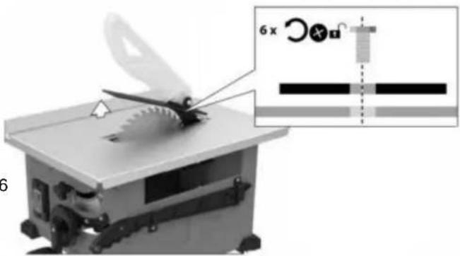
natural_image
Mechanical device with scissors and a magnified inset showing a 6x x magnification (no text or symbols on the device itself)FIG.12
HIGO. 13
HIGO. 14
natural_image
Mechanical assembly diagram showing a beam with mounting holes and a directional arrow (no text or symbols)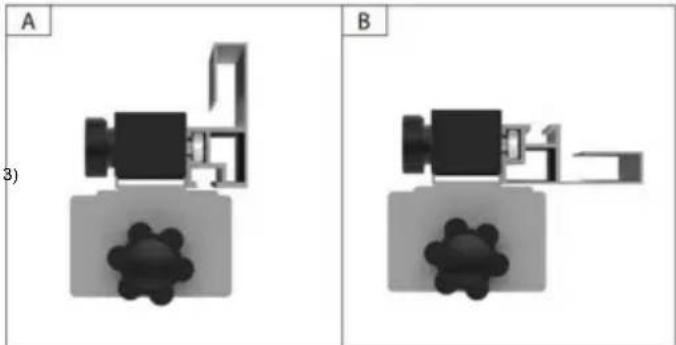
natural_image
Two identical 3D mechanical assembly diagrams labeled A and B, showing internal components without any text or symbols.Machine Translated by Google
natural_image
Mechanical assembly diagram showing two rotating components with a padlock icon (no text or symbols)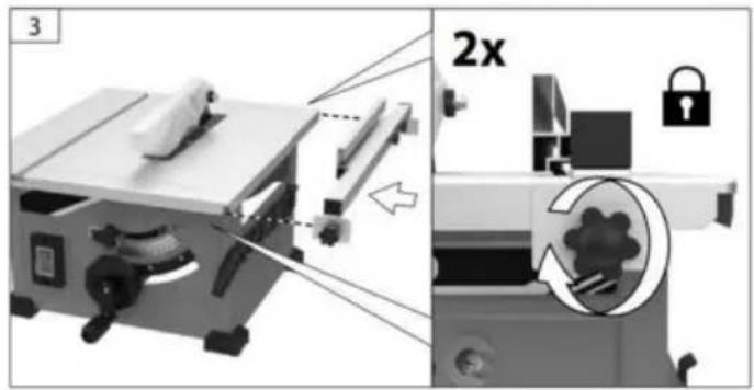
natural_image
Two grayscale diagrams showing a wooden plank under load with arrows indicating force or movement, no text or symbols present.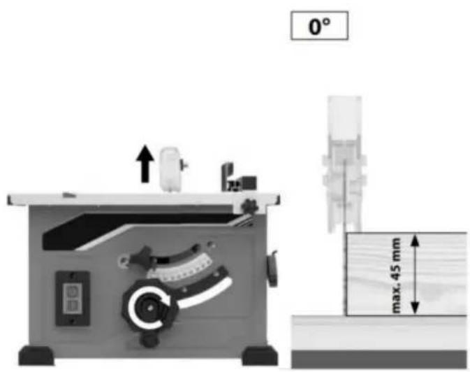
natural_image
Diagram of a gear and blade assembly with labeled section A (no text or symbols on the diagram itself)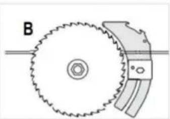
natural_image
Diagram of a gear and blade assembly with labeled component B (no text or symbols present)FIG.41
FIG.42
natural_image
Illustration of hands cleaning a wall with a tool, no text or symbols presentFIG.51
DESGARRO EN BISEL
natural_image
Illustration showing hands holding a tool and a knife, with a magnified inset of the knife (no text or symbols)FIG.52

natural_image
Illustration of a person using a tool to lift a wall-mounted device, with an inset showing a blade being cut (no text or symbols)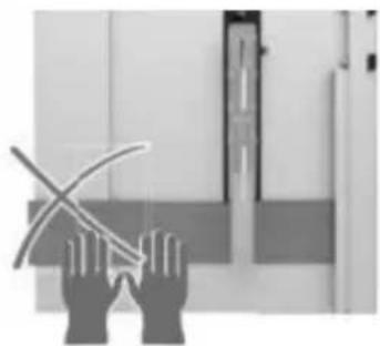
natural_image
Silhouette of two hands holding a curved object, possibly a tool or device, against a plain background (no text or symbols visible)natural_image
Top-down view of a mechanical assembly with a close-up inset showing internal components (no text or symbols visible)CORTE TRANSVERSAL EN BISEL
Peso ....a prox. 13,0 kilos
Machine Translated by Google
natural_image
Industrial machine with workpiece and control panel (no visible text or symbols)POTRZEBUJESZ POMOCY? SKONTAKTUJ SIĘ Z NAMI!
BEZPIECZEŃ STWO W MIEJSCU PRACY
natural_image
Icon of a person wearing glasses inside a circle (no text or symbols)
USUŃ TAŚMĘ KABLOWA I BLOK
natural_image
Exterior view of a small metal workbench with visible blades and control knobs (no text or symbols)2
4
5
3
natural_image
Two metallic mechanical components with cylindrical bases, no visible text or symbols6

RYS.4
Montaż
natural_image
Two views of a machine cutter shop with internal components, showing external and internal assembly (no text or symbols visible)FIG.7
RYS.6

Montaż

OSTERZEŻENIE

OSTRZEŻENIE
Do czerwonego ce u
pił y jeździć
ryzyko
W
zranienia ostjøy
natural_image
Mechanical assembly diagram showing a saw cutting machine with three views of the tool (no text or labels present)FIGA. 13
FIGA. 14
natural_image
Mechanical assembly diagram showing a beam with mounting holes and a directional arrow (no text or symbols)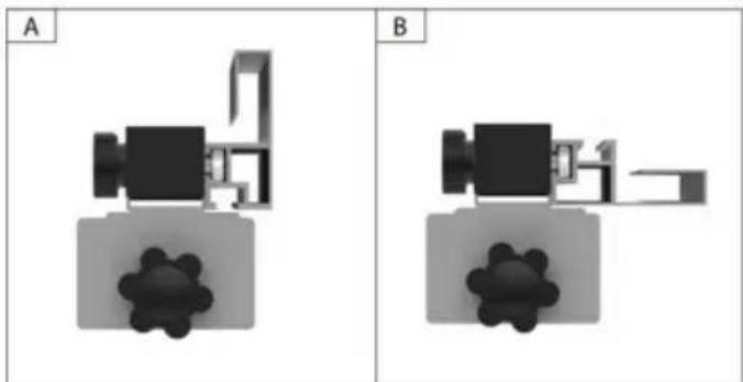
natural_image
Two identical mechanical or architectural diagrams labeled A and B, each showing a component with a gear-like base (no text or symbols present)Machine Translated by Google
natural_image
Diagram showing a mechanical assembly with two circular components and a lock icon, no text or symbols present.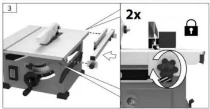
natural_image
Two grayscale diagrams showing a wooden plank under load with arrows indicating force or movement, no text or symbols present.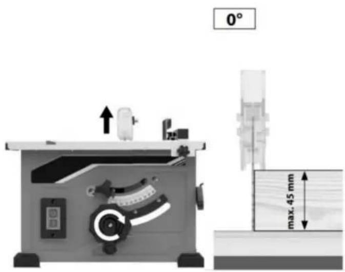
natural_image
Two mechanical diagrams labeled A and B showing gear meshing with no visible text or symbols.RYS.41
RYS.42
MOCOWANIE MONTAŻU OSŁONY
natural_image
Illustration of hands cleaning a wall with a tool, no text or symbols presentRYS.51
natural_image
Illustration showing hands holding a tool and a knife, with a magnified inset of the knife (no text or symbols)RYS.52
natural_image
Illustration of hands cleaning a wall with a magnified inset showing a blade (no text or symbols)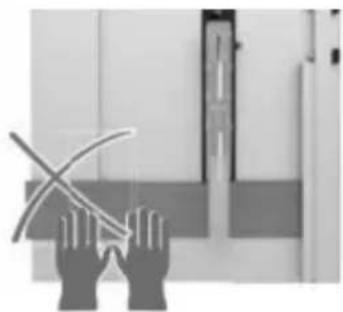
natural_image
Illustration of two hands holding a curved object, possibly a tool or device, against a plain background (no text or symbols)natural_image
Top-down diagram of a mechanical device with a cylindrical component and a close-up inset showing internal components (no text or symbols)PRZECIĘCIE KOSZOWE
Machine Translated by Google
natural_image
Industrial machine with workpiece and control panel (no visible text or symbols)HULP NODIG? NEEM CONTACT MET ONS OP!
BEWAKING VAN GERELATEERDE WAARSCHUWINGEN
GERELATEERDE WAARSCHUWINGEN
TAFELZAAG IN WERKING PROCEDURE-WAARSCHUWINGEN
Standards Association
natural_image
Icon of a person wearing glasses inside a circle (no text or symbols)
natural_image
Exterior view of a small metal workbench with visible blades and control knobs (no text or symbols)2
4
5
3
natural_image
Two metallic mechanical components with cylindrical bases, no visible text or symbols6

FIG.4
Montage
DE Mesbeschermer BEVESTIGEN

WAARSCHUWING
natural_image
Two views of a machine cutter shop with internal components, showing front and side views (no text or symbols visible)FIG.7
FIG.6
Montage
VERWIJDEREN EN INSTALLEREN VAN HET MES Haal de stekker

WAARSCUWING
Om het risico van
natural_image
Mechanical device with a paper feeding into a tray, shown from two different angles (no text or symbols visible)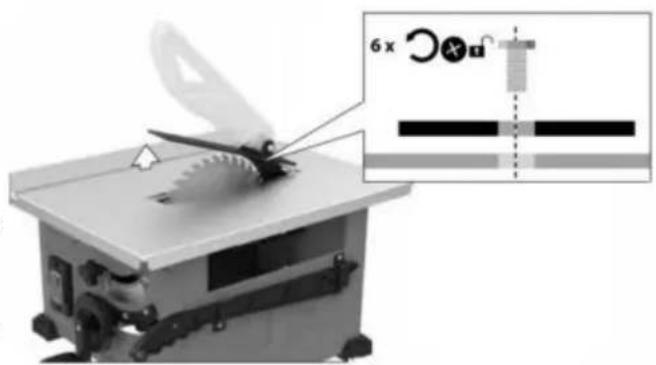
natural_image
Mechanical device with a cutting tool and a 6x magnified inset showing a mechanical component (no text or symbols visible)FIG.12
AFB. 13
AFB. 14
natural_image
Mechanical assembly diagram showing a beam with mounting holes and a directional arrow (no text or symbols)A
natural_image
Abstract 3D rendering of a camera and a gear-like object (no text or symbols)B
natural_image
Pure electrical circuit lines without any symbolsMachine Translated by Google
natural_image
Mechanical assembly diagram showing two rotating components with a lock icon (no text or symbols)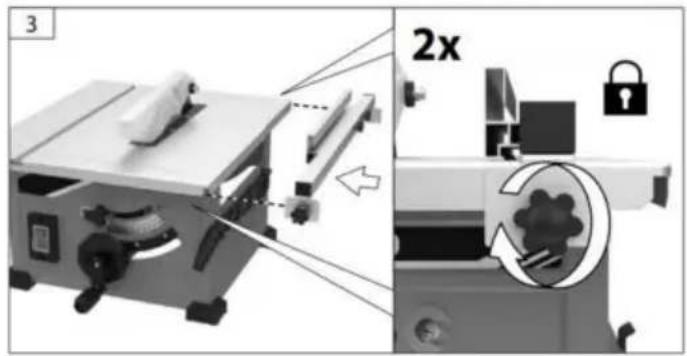
natural_image
Two grayscale diagrams showing a wooden plank under load with arrows indicating force or movement, no text or symbols present.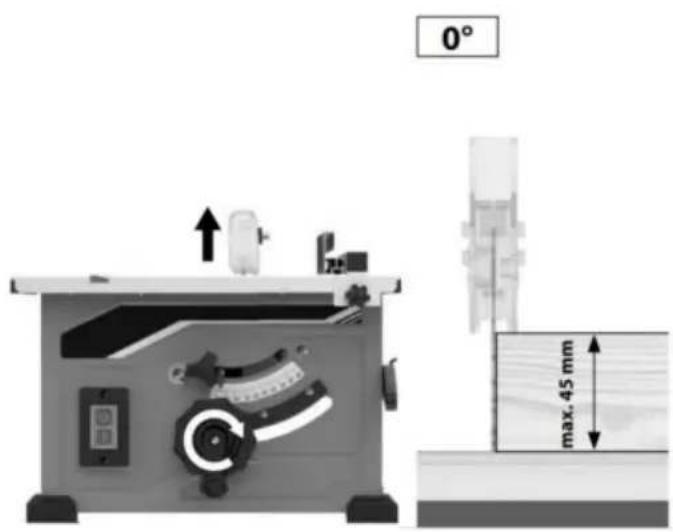
natural_image
Two mechanical diagrams labeled A and B showing gear meshing with no visible text or symbols.FIG.41
FIG.42
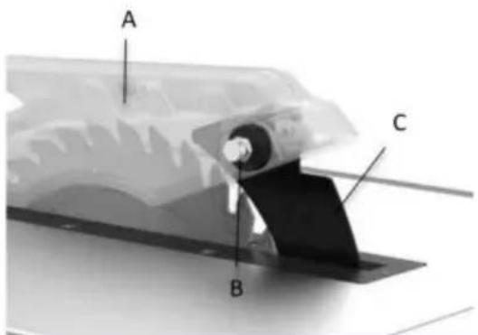
BEVESTIGING VAN DE BESCHERMING
natural_image
Illustration of hands cleaning a wall with a tool, no text or symbols presentFIG.51
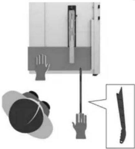
natural_image
Illustration showing hands holding a tool and a knife, with a magnified inset of the knife (no text or symbols)FIG.52
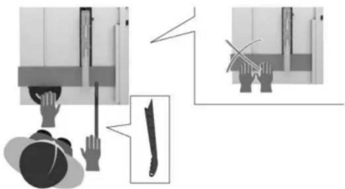
natural_image
Illustration of a person using a tool to lift a wall-mounted device, with an inset showing a blade being cut (no text or symbols)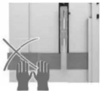
natural_image
Silhouette of two hands holding a curved object, possibly a tool or device, against a plain background (no text or symbols visible)natural_image
Top-down diagram of a mechanical device with a cylindrical component and a close-up inset showing internal components (no text or symbols)BEVEL-KRUISSNIJDING
Machine Translated by Google
natural_image
Industrial machine with workpiece and control panel (no visible text or symbols)BEHÖVER HJÄLP? KONTAKTA OSS!
natural_image
Icon of a person wearing glasses inside a circle (no text or symbols)WARNING
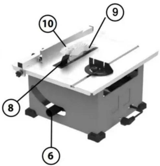
natural_image
Exterior view of a small metal workbench with visible blades and control knobs (no text or symbols)2

4
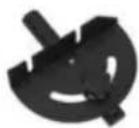
5
3
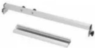
natural_image
Two metallic mechanical components with cylindrical shafts, no visible text or symbols6

FIG.4
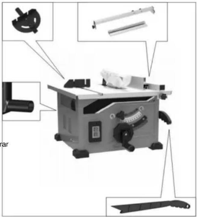
Montering
ATT FÄSTA STYRKET
WARNING
natural_image
Two views of a machine cutter shop with visible internal components and a directional arrow indicating motion (no text or symbols)FIG.7
FIG.6
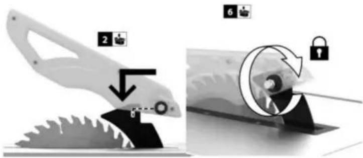
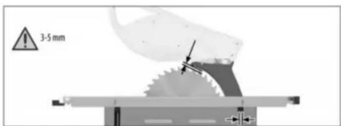
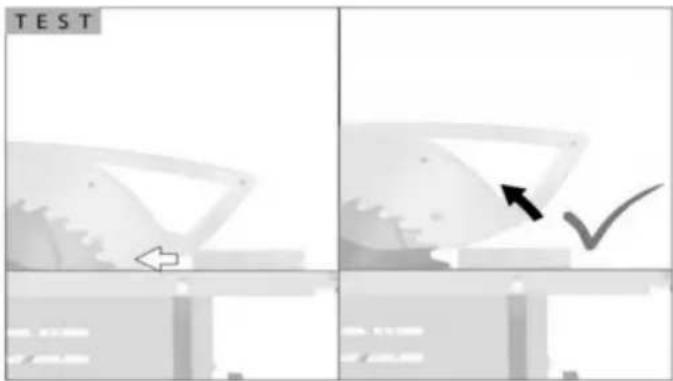
Montering
DEMONTERING OCH INSTALLATION AV BLADET Koppla ur
WARNING
natural_image
Mechanical assembly diagram showing a cutting machine with a tool and a close-up view of the internal components (no text or symbols visible)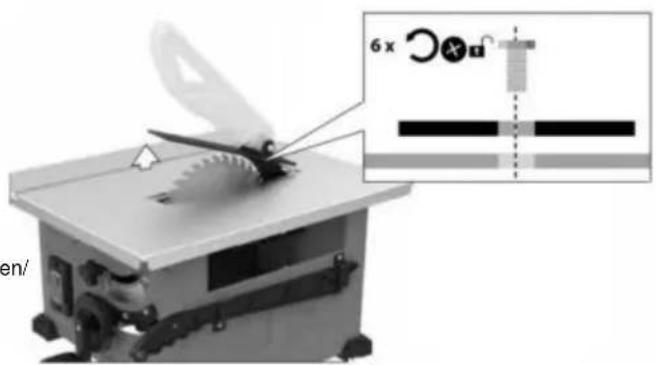
FIG.12
Till reda ce u ság
risk för knivar
inj i m arida på
natural_image
Mechanical assembly diagram showing a saw cutting machine with three views of the tool (no text or labels present)FIKON. 13
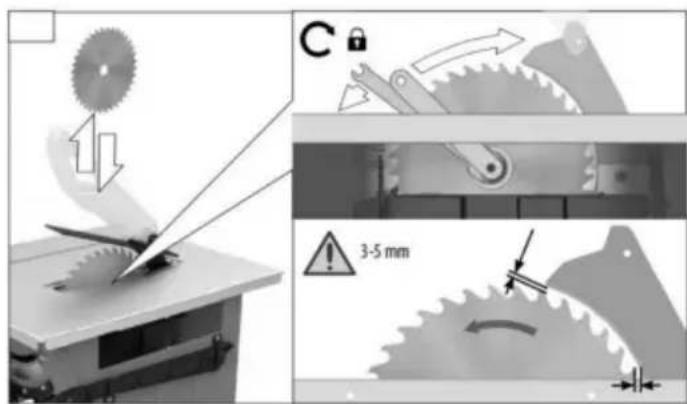
FIKON. 14
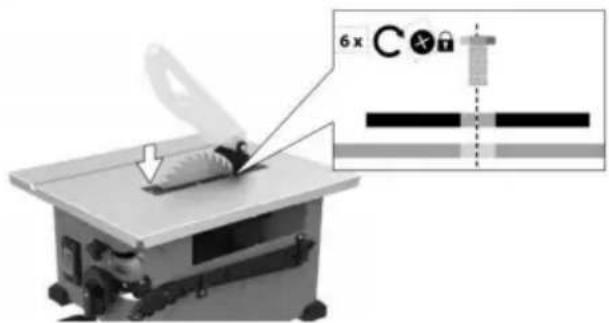
natural_image
Mechanical assembly diagram showing a beam with mounting holes and a directional arrow (no text or symbols)A
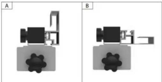
natural_image
Two identical 3D floor plan diagrams labeled A and B, showing room layouts and structural elements without any text or symbols.Machine Translated by Google
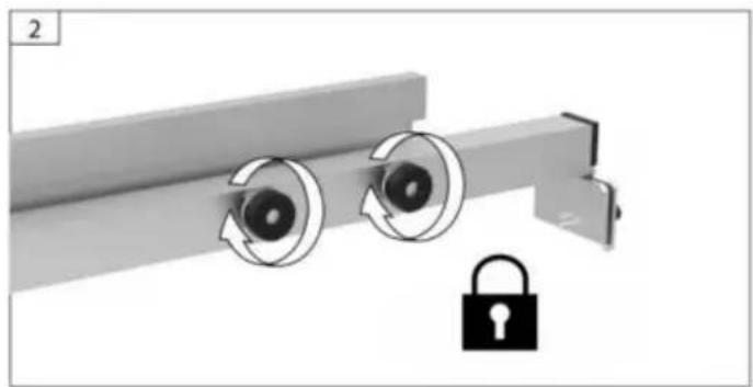
natural_image
Mechanical assembly diagram showing two rotating components with a padlock icon (no text or symbols)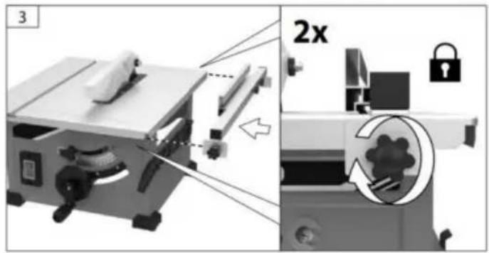
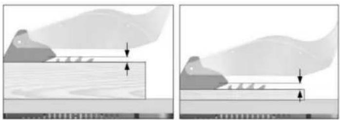
natural_image
Two diagrams showing a wooden plank under load with arrows indicating force direction, no text or symbols present.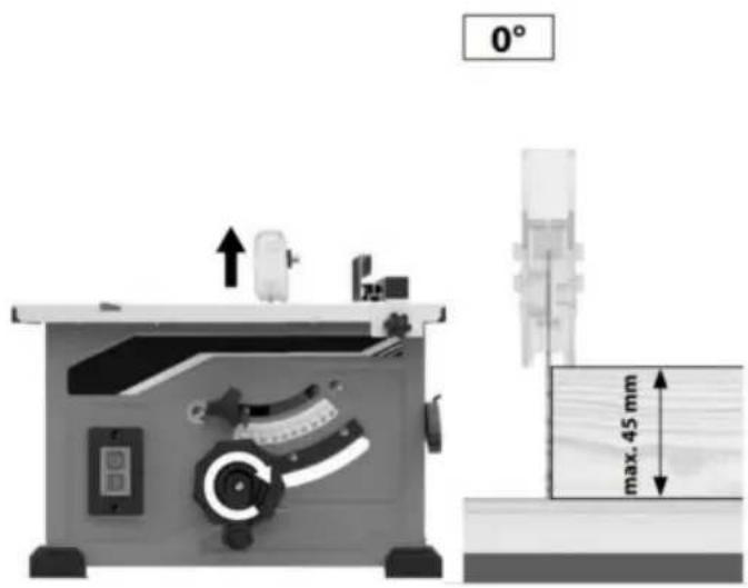
natural_image
Diagram of a saw cutting tool with labeled section A, showing blade and gear components (no text or symbols beyond label)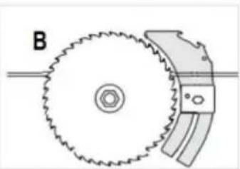
natural_image
Diagram of a mechanical gear assembly with labeled component B (no text or symbols on the diagram itself)FIG.41
FIG.42
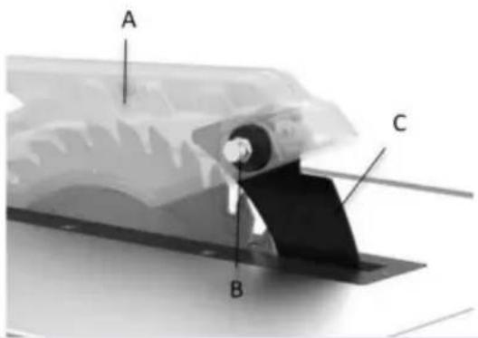
FÄSTNING AV SKYDDMONTAGET
natural_image
Illustration of hands cleaning a wall with a tool, no text or symbols presentFIG. 51

natural_image
Illustration showing hands holding a tool and a knife, with a magnified inset of the knife (no text or symbols)FIG. 52
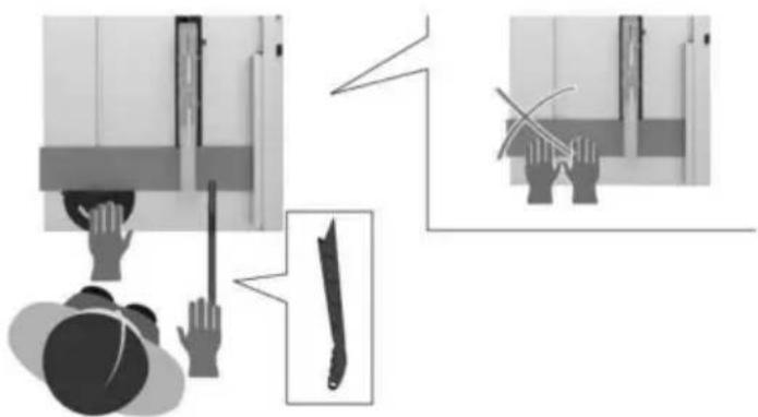
natural_image
Illustration of a person using a tool to lift a wall-mounted device, with an inset showing a blade being cut (no text or symbols)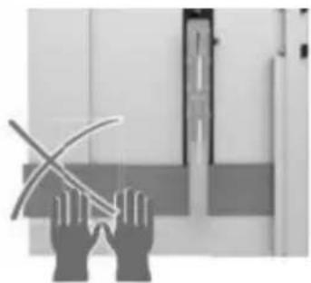
natural_image
Silhouette of two hands holding a curved object, possibly a tool or device, against a plain background (no text or symbols visible)natural_image
Top-down diagram of a mechanical device with a close-up inset showing internal components (no text or symbols)AVFANSNING
Machine Translated by Google
- ELECTRIC TABLE SAW USER MANUAL
- VEVOR®
- ELECTRIC TABLE SAW
- MODEL:WTS210F
- NEED HELP? CONTACT US!
- Table of Contents
- WARNING
- General Safety Rules
- SAVE ALL WARNINGS AND INSTRUCTIONS FOR FUTURE REFERENCE.
- WORK AREA SAFETY
- ELECTRICAL SAFETY
- PERSONAL SAFETY
- POWER TOOL USE AND CARE
- SAVE THESE INSTRUCTIONS
- SERVICE
- Safety Instructions for Table Saws
- GUARDING RELATED WARNINGS
- CUTTING PROCEDURES WARNINGS
- KICKBACK CAUSES AND RELATED WARNINGS
- Additional Safety Rules
- TABLE SAW STAND SAFETY INSTRUCTIONS
- Motor Specifications & Electrical Requirements
- Motor Specifications
- Connection To A Power Source
- Extension Cords
- technicians
- parts
- Symbols
- Safety Symbols
- Damage Prevention and Information Messages
- Symbols (Certification Information)
- Glossary of Terms
- Getting To Know Your Table Saw
- ELEVATION WHEEL
- POWER SWITCH
- BEVEL SCALE
- BLADE BEVEL LOCK HANDLE
- RIP FENCE
- DUST PORT/VACUUM HOOK-UP
- MITER GAUGE
- RIVING KNIFE
- SAW BLADE
- BLADE GUARD
- PUSH STICK
- Unpacking And Checking Contents
- REMOVE CABLE TIE AND STYROFOAM BLOCK
- Assembly
- ATTACHING THE Blade Guard
- WARNING To prevent personal injui always disconnect the plug FIG.5
- ATTACHING THE GUARD ASSEMBLY
- REMOVAL AND INSTALLATION OF THE BLADE
- USING THE CORRECT BLADE
- CHANGING THE BLADE
- USING CARBIDE-TIPPED BLADES
- ATTACHING RIP FENCE FOR USE
- Basic Table Saw Operation
- SAFETY POWER SWITCH
- RESET BUTTON (POWER RESET)
- USING THE Blade Guard
- BBLADE BEVEL CONTROL
- USING THE RIP FENCE
- RIPPING
- BEVEL RIPPING
- To adjust the miter angle:
- MITER GAUGE AUXILIARY FACING
- Example:
- CROSSCUTTING
- REPETITIVE CUTTING
- MITER CUTTING
- Maintaining Your Table Saw
- LUBRICATION
- Danger!
- Cleaning
- Carbon brushes
- Maintenance
- Ordering replacement parts:
- Troubleshooting
- Turnswitch“OFF”andalwaysremoveplugfromthepowersourcebeforetroubleshootir
- TECHNICAL DATA
- TOUGH TOOLS, HALF PRICE
- BESOIN D'AIDE ? CONTACTEZ-NOUS!
- Assemblée
- FIXATION DU PROTÈGE-LAME
- AVERTISSEMENT
- RETRAIT ET INSTALLATION DE LA LAME
- FIGUE. 13
- FIGUE. 14
- Machine Translated by Google
- FIXATION DE L'ENSEMBLE DE PROTECTION
- DÉCHIRURE EN BISEAUX
- KABELBINDER UND
- STYROPORBLOCK ENTFERNEN
- Montage
- ENTFERNEN UND INSTALLIEREN DER KLINGE
- Abb. 13
- Abb. 14
- FASENKREISSCHNITT
- Assemblea
- Asamblea
- USO DE LA HOJA CORRECTA
- ADVERTENCIA
- HIGO. 13
- HIGO. 14
- DESGARRO EN BISEL
- BEZPIECZEŃ STWO W MIEJSCU PRACY
- Montaż
- OSTERZEŻENIE
- OSTRZEŻENIE
- PRZECIĘCIE KOSZOWE
- HULP NODIG? NEEM CONTACT MET ONS OP!
- BEWAKING VAN GERELATEERDE WAARSCHUWINGEN
- GERELATEERDE WAARSCHUWINGEN
- TAFELZAAG IN WERKING PROCEDURE-WAARSCHUWINGEN
- DE Mesbeschermer BEVESTIGEN
- WAARSCHUWING
- VERWIJDEREN EN INSTALLEREN VAN HET MES Haal de stekker
- WAARSCUWING
- Om het risico van
- 13
- 14
- BEVESTIGING VAN DE BESCHERMING
- BEVEL-KRUISSNIJDING
- BEHÖVER HJÄLP? KONTAKTA OSS!
- Montering
- ATT FÄSTA STYRKET
- DEMONTERING OCH INSTALLATION AV BLADET Koppla ur
- FIKON. 13
- FIKON. 14
- A
- FÄSTNING AV SKYDDMONTAGET
Brand : Vevor
Model : WTS210F
Category : Saw