USER MANUAL SX2806 Vevor
Technical Support and E-Warranty Certificate www.vevor.com/support
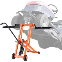
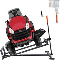
LAWN MOWER LIFT
MODEL: SX2806
We continue to be committed to providing you with tools at competitive prices. "Save Half," "Half Price," or any other similar expressions used by us only represent an estimate of savings you might benefit from buying certain tools with us compared to the major top brands and do not necessarily mean to cover all categories of tools offered by us. You are kindly reminded to verify carefully when placing an order with us if you are actually saving half in comparison with the top major brands.
MODEL: SX2806
Have product questions? Need technical support? Please feel free to contact us:
Technical Support and E-Warranty Certificate www.vevor.com/support
This is the original instruction. Please read all manual instructions carefully before operating. VEVOR reserves a clear interpretation of our user manual. The appearance of the product shall be subject to the product you received. Please forgive us that we won't inform you again if there are any technology or software updates on our product.
GENERAL GUIDELINES & SAFETY
- It is the user's responsibility to read and follow all instructions.
- Keep these instructions with the product at all times and review before each use.
- It is the responsibility of this product's owner to furnish the instructions to any person who borrows or purchases the product.
- Inspect the product before use to ensure it is assembled properly and all parts are in safe working order and free of defects.
- Never modify this product in any way.
- All circumstances cannot be addressed in these instructions.
- Please use common sense and practice general safety measures when using this product. Parts and/or instructions are subject to change without notice.
- Do not exceed the rated weight capacity of 500 lbs. Always ensure the mower wheels fit properly into the wheel cradles before lifting.
- Secure the mower with tie down straps (sold separately) before lifting. Always lock the brake pullers before working on the mower.
- Store the lift in a safe, dry place.
SPECIFICATIONS
| MAXIMUM CAPACITY | 500lbs(225kg) |
| LIFT RANGE | 0-25.9inch(0-658mm) |
BLEEDING THE HYDRAULIC JACK
IMPORTANT! Before first use, check for proper hydraulic fluid level in the hydraulic pump (11). Then thoroughly test the lift for proper operation prior to actual use. If the lift appears not to be working properly, it may be necessary to bleed its hydraulic system of excess air.
Step 1. Remove the fluid fill plug on the side of the bottle jack.
Step 2. With weight on the lift, turn the pump handle (26) counterclockwise to release the valve.
Step 3. While holding the weight and pump in the released position, quickly move the handle (26) up and down several times to purge air from the system.
Step 4. Check the fluid fill hole and, if necessary, top off the jack's fluid reservoir with hydraulic jack fluid (sold separately).
Step 5. Replace the fluid fill plug.
Step 6. Test the lift several times for proper operation before attempting to load.
If, after purging, the lift still does not appear to be working properly, do not use the lift until it has been repaired by a qualified service technician.
LIFTING THE JACK
Step 7. Pull out (unlock) the locking pin (18) of the safety device on both sides of the lift.
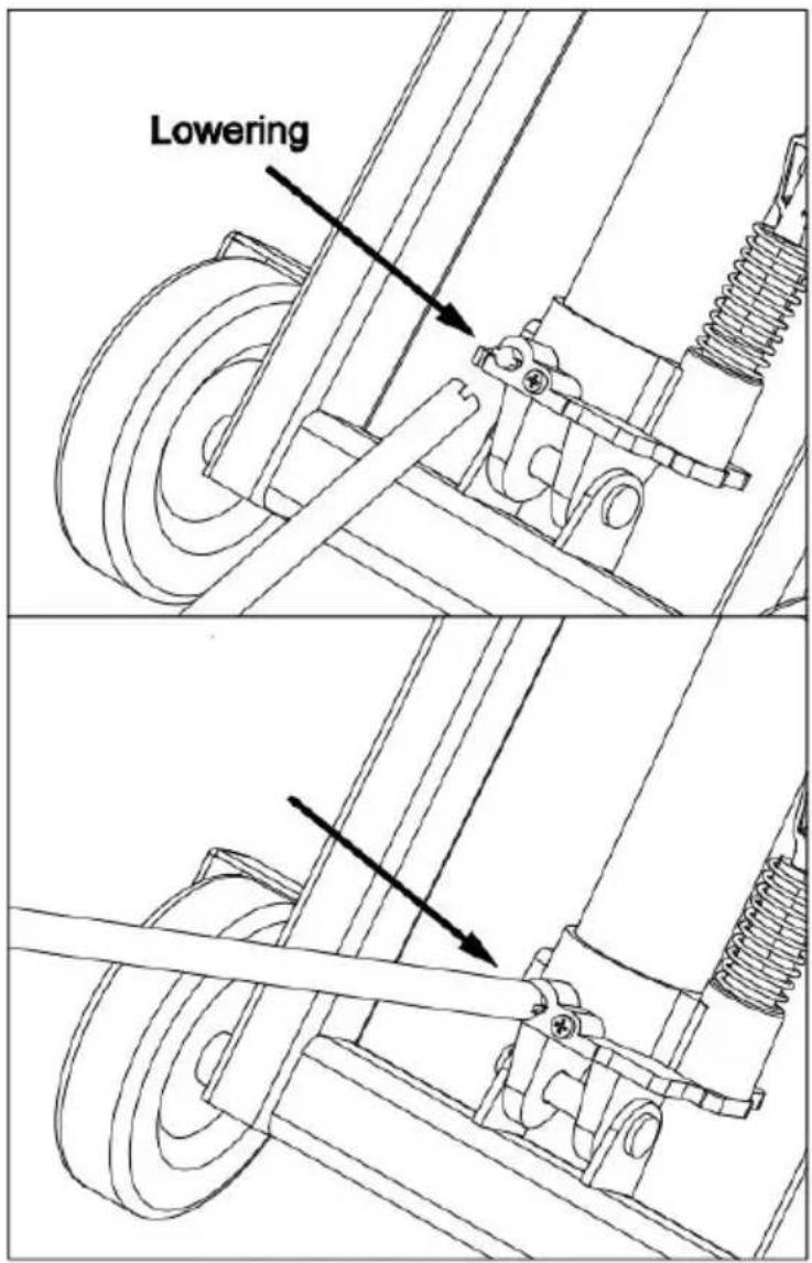
Step 8. Lower the lift by releasing the wing nut on the jack with the notched end of the handle (26); put some weight on the cradles if necessary. Once lowered, tighten the wing nut again.
Step 9. Align the mower's wheels with both cradles. Slowly move the mower onto the cradles. Once positioned under the load, push back the locking pin (18) on both sides of the lift. (You may need to chock the backside of the casters to keep the lift sturdy while riding on the mower).
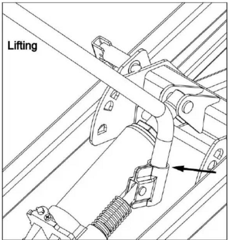
locking pin (18) on both sides of the lift. (You may need to chock the wheel backside of the casters to keep the lift sturdy while riding on the mower).
Step 10. Use tie-down straps (sold separately) to secure the load. Fit the curved end of the handle (26) into the handle tube on the jack. Pump the handle slowly to raise the lift. When the lift makes contact with the load, make sure the load sits evenly on the cradles (1) before raising the load. If the load is not distributed on the two cradles (1) or not secured in place with tie-down straps, it may fall from the lift, resulting in personal injury and property damage.
load sits evenly on the cradles (1) before raising the load. If the load is no distributed on the two cradles(1) or not secured in place with tie-down straps may fall from the lift, resulting in personal injury and property damage.
Step 11. Continue to raise the lift to the desired height. Lock the lift at one of three locking positions on the locking pin (18). Not engaging the locking pin may result in serious injury or death, and damage the lift. See mower owner manual for recommended lifting points.
- Press the ON/OFF button to switch the product on. The display shows "0".
- Place an item on the weighing plate. Wait for the readout on the display to stabilize.
- After use, press the ON/OFF button to switch the product off.
LOWERING THE JACK
Step 12. Carefully remove all parts, etc. from under the lift.
Step 13. Fit the curved end of handle (26) into the handle turn on the jack. Pump the handle slowly to raise the lift enough to disengage the locking pin (18).
Step 14. Slowly release the wing nut on the jack with the notched end of the handle (26) to lower the load slowly and gently.
Never allow the load to come down quickly or suddenly.
Step 15. Once the load is on the ground, remove the tie-down straps.
Step 16. Clean the external surface of the lift with a clean, dry cloth. Store the lift in a dry, indoor area out of the reach of children.
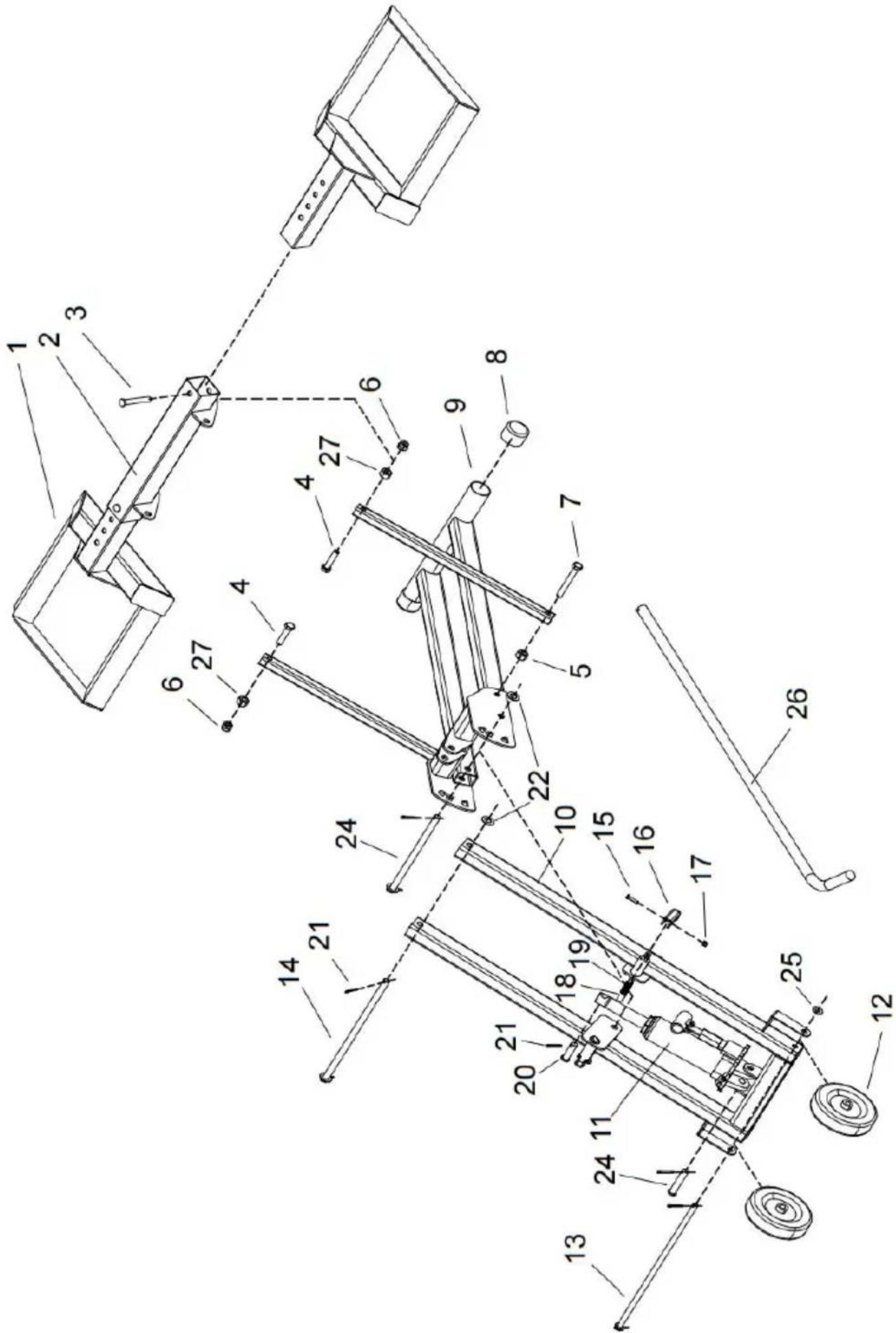
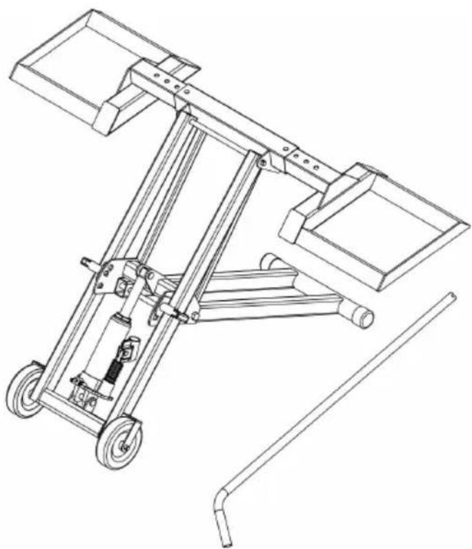
| PART | DESCRIPTION | QTY | PART | DESCRIPTION | QTY |
| 1 | Wheel Disc Holder | 2 | 15 | Bolt M4x20 | 2 |
| 2 | Connecting Pipe | 1 | 16 | Press | 2 |
| 3 | Pin φ10X65 | 2 | 17 | Nut M4 | 2 |
| 4 | Bolt M10x45 | 2 | 18 | Pin φ12 | 2 |
| 5 | Nut M12 | 2 | 19 | Spring | 2 |
| 6 | Lock Nut M10 | 4 | 20 | Pin φ12X42 | 1 |
| 7 | Bolt M10x75 | 2 | 21 | Pin φ3X25 | 8 |
| 8 | Plug Head | 2 | 22 | φ12 Washer | 4 |
| 9 | Support Frame 1# | 1 | 23 | Pin φ12X212 | 1 |
| 10 | Support Frame 2# | 1 | 24 | Pin φ12X62 | 1 |
| 11 | Pump | 1 | 25 | φ10 Washer | 2 |
| 12 | 5" Wheel | 2 | 26 | Operating Handle | 1 |
| 13 | Pin φ10X355 | 1 | 27 | Nut M10 | 2 |
| 14 | Pin φ12X285 | 1 | | | |
Manufacturer: Shanghai Muxin Muye Youxiangongsi
Address: Shuangchenglu 803nong11hao1602A-1609shi, Baoshanqu, Shanghai 200000 CN.
Imported to AUS: SIHAO PTY LTD. 1 ROKEVA STREET, EASTWOOD NSW 2122 Australia
Imported to USA: Sanven Technology Ltd. Suite 250, 9166 Anaheim Place, Rancho Cucamonga, CA 91730
YH CONSULTING LIMITED. C/O YH Consulting Limited Office 147, Centurion House, London Road, Staines-upon-Thames, Surrey, TW18 4AX
Technical Support and E-Warranty Certificate
www.vevor.com/support
VEVOR®
E-CrossStu GmbH
Mainzer Landstr. 69,
YH CONSULTING LIMITED. C/O YH Consulting
www.vevor.com/support
VEVOR®
Imported into AUS: SIHAO PTY LTD. 1 ROKEVA STREET EASTWOOD NSW 2122 Australia
Street, Staines-upon-Thames, Surrey, TW18 4AX
E-CrossStu GmbH
Mainzer Landstr. 69,
electronics www.vevor.com/support
VEVOR®
www.vevor.com/support
Road, Staines upon Thames, Surrey, TW18 4AX
E-CrossStu GmbH
Mainzer Landstr.69,
NEED HELP? CONTACT US!
Road, Staines-upon-Thames, Surrey, TW18 4AX
E-CrossStu GmbH
Mainzer Landstr.69,
60329 Frankfurt am Main.
VEVOR®
TOUGH TOOLS, HALF PRICE
www.vevor.com/support
VEVOR®
Technical support and e-warranty certificate www.vevor.com/support
LAWN MOWER LIFT
MODEL: SX2806
NEED HELP? CONTACT US!
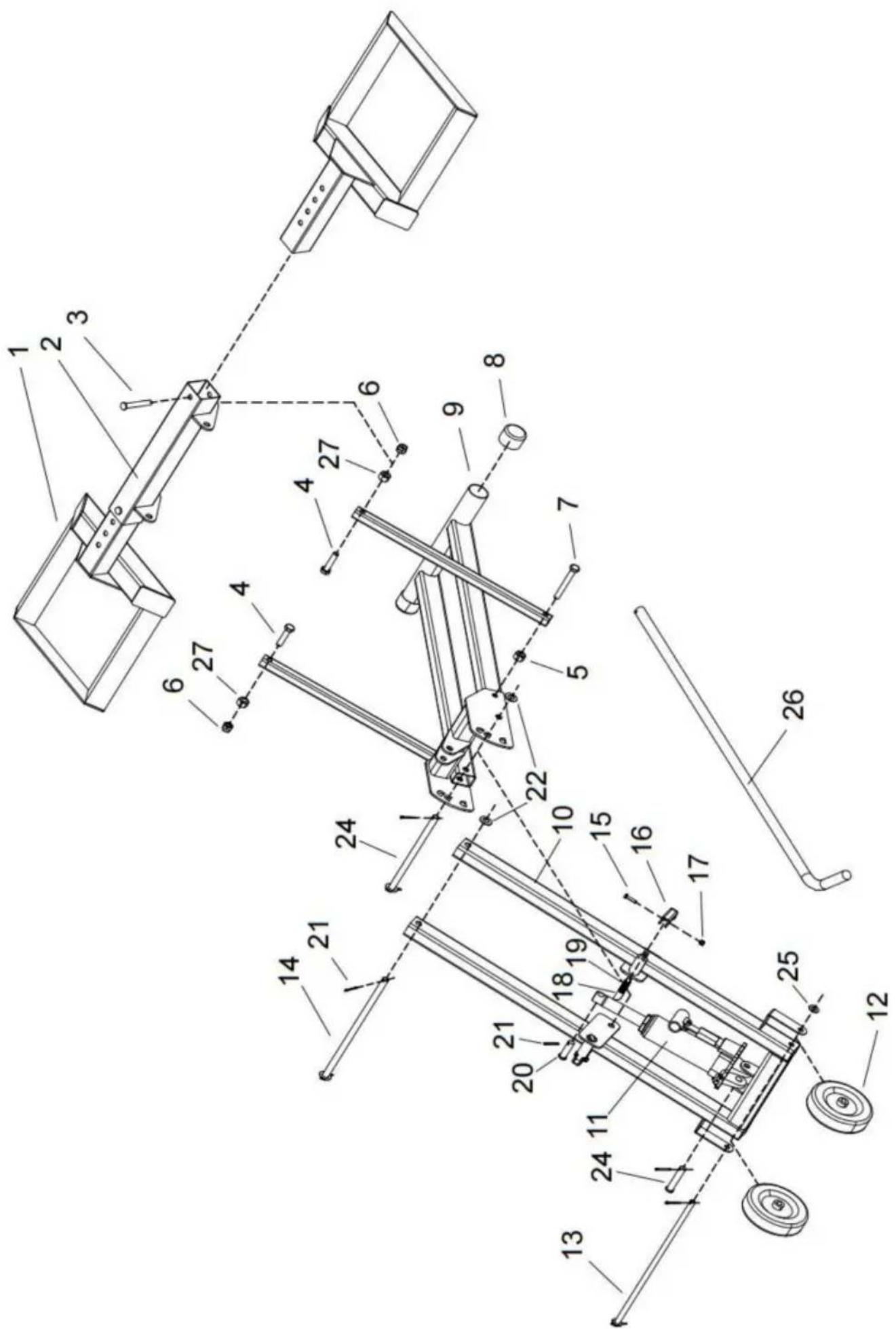
| DEEL | BESCHRIJVING | AANTAL | ONDER | DEEL BESCHRIJVING | AANTAL |
| 1 | Houder voor wielschijven | 2 | 15 | Bout M4x20 | 2 |
| 2 | Aansluitleiding | 1 | 16 | Druk op | 2 |
| 3 | Pen y10X65 | 2 | 17 | Moer M4 | 2 |
| 4 | Bout M10x45 | 2 | 18 | Pin y12 | 2 |
| 5 | Moer M12 | 2 | 19 | Lente | 2 |
| 6 | Borgmoer M10 | 4 | 20 | Pen y12X42 | 1 |
| 7 | Bout M10x75 | 2 | 21 | Pen y3X25 | 8 |
| 8 | Stekker hoofd | 2 | 22 | y12 Ring | 4 |
| 9 | Steunframe 1# | 1 | 23 | Pen y12X212 | 1 |
| 10 | Steunframe 2# | 1 | 24 | Pen y12X62 | 1 |
| 11 | Pomp | 1 | 25 | y10 Sluitring | 2 |
| 12 | 5" wiel | 2 | 26 | Bedieningshendel | 1 |
| 13 | Pen y10X355 | 1 | 27 | Moer M10 | 2 |
| 14 | Pen y12X285 | 1 | | | |
Manufacturer: Shanghaimuxinmuyeyouxiangongsi
Address: Shuangchenglu 803nong11hao1602A-1609shi, baoshanqu, shanghai 200000 CN.
YH CONSULTING LIMITED. C/O YH Consulting
Limited office 147, Centurion House, London
Road, Staines-upon-Thames, Surrey, TW18 4AX
E-CrossStu GmbH
Mainzer Landstr.69,
60329 Frankfurt am Main.
VEVOR®
TOUGH TOOLS, HALF PRICE
warranty certificate www.vevor.com/support
VEVOR®
NEED HELP? CONTACT US!
| DELBESKRIVNING | ANTAL | DEL BESKRIVNING | ANTAL |
| 1 | Hjulskivhållare | 2 | 15 | Bult M4x20 | 2 |
| 2 | Anslutningsrör | 1 | 16 | Trycka | 2 |
| 3 | Stift ÿ10X65 | 2 | 17 | Mutter M4 | 2 |
| 4 | Bult M10x45 | 2 | 18 | Pin ÿ12 | 2 |
| 5 | Mutter M12 | 2 | 19 | Fjädra | 2 |
| 6 | Låsmutter M10 | 4 | 20 | Stift ÿ12X42 | 1 |
| 7 | Bult M10x75 | 2 | 21 | Stift ÿ3X25 | 8 |
| 8 | Plugghuvud | 2 | 22 | ÿ12 Bricka | 4 |
| 9 | Stödram 1# | 1 | 23 | Stift ÿ12X212 | 1 |
| 10 | Stödram 2# | 1 | 24 | Stift ÿ12X62 | 1 |
| 11 | Pump | 1 | 25 | ÿ10 Bricka | 2 |
| 12 | 5" hjul | 2 | 26 | Manöverhandtag | 1 |
| 13 | Stift ÿ10X355 | 1 | 27 | Mutter M10 | 2 |
| 14 | Stift ÿ12X285 | 1 | | | |
Manufacturer: Shanghaimuxinmuyeyouxiangongsi
Address: Shuangchenglu 803nong11hao1602A-1609shi, baoshanqu, shanghai 200000 CN.
Imported to AUS: SIHAO PTY LTD. 1 ROKEVA STREETEASTWOOD NSW 2122 Australia
Imported to USA: Sanven Technology Ltd. Suite 250, 9166 Anaheim Place, Rancho Cucamonga, CA 91730
YH CONSULTING LIMITED. C/O YH Consulting
Limited Office 147, Centurion House, London
Road, Staines-upon-Thames, Surrey, TW18 4AX
E-CrossStu GmbH
Mainzer Landstr.69,
60329 Frankfurt am Main.
VEVOR®
TOUGH TOOLS, HALF PRICE
www.vevor.com/support