
SBC150 - Sandblasting cabinet Vevor - Free user manual and instructions
Find the device manual for free SBC150 Vevor in PDF.
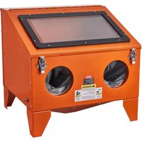


| Product Type | Sandblast Cabinet |
| Model | SBC150 |
| Brand | Vevor |
| Material | Steel |
| Maximum Air Pressure | 90 psi (6.2 bar) |
| Maximum Abrasive Capacity | 10 lb (4.5 kg) |
| Lighting | Built-in LED Lamp |
| Viewing Window | Replaceable plexiglass with protective film |
| Gloves | Included (one pair, left and right) |
| Nozzles Supplied | 4 sizes: 4.5 mm, 5 mm, 6 mm, 7 mm |
| Blast Gun | Included with air and sand hose |
| Power Supply | Mains transformer (230 V / 50 Hz, estimated) |
| Compatible Abrasive Types | Glass beads, silicon carbide, aluminum oxide, silica sand (dry) |
| Dust Extraction System | Recommended (detachable exhaust plug) |
| Doors | Double door with lock |
| Gas Springs | 2 springs for window support |
| Air Filter | Included (inner filter plate) |
| Safety | Light switch, air valve, detailed safety instructions |
| Maintenance | Regular cleaning of vent, check for leaks, replace worn abrasive |
| Warranty | Technical support and electronic warranty certificate at www.vevor.com/support |
| Compliance | FCC Part 15, WEEE Directive 2012/19/EU |
Frequently Asked Questions - SBC150 Vevor
User questions about SBC150 Vevor
0 question about this device. Answer the ones you know or ask your own.
Ask a new question about this device
Download the instructions for your Sandblasting cabinet in PDF format for free! Find your manual SBC150 - Vevor and take your electronic device back in hand. On this page are published all the documents necessary for the use of your device. SBC150 by Vevor.
USER MANUAL SBC150 Vevor
Technical Support and E-Warranty Certificate www.vevor.com/support
SAND BLASTER CABINET
MODEL: SBC150
We continue to be committed to providing you tools with competitive prices. "Save Half", "Half Price", or any other similar expressions used by us only represent savings you might benefit from buying certain tools with us compared to top brands and does not necessarily mean to cover all categories of tools offered. We kindly remind you to verify carefully when placing an order with us to ensure you are actually saving half in comparison with the top major brands.
MODEL: SBC150
NEED HELP? CONTACT US!
Have product questions? Need technical support? Please feel free to contact us:
Technical Support and E-Warranty Certificate www.vevor.com/support
This is the original instruction. Please read all manual instructions carefully before operating. VEVOR reserves the right to interpret the user manual. The appearance of the product shall be subject to the product you received. Please forgive us that we won't inform you of any technology or software updates on our product.
1. SAFETY INSTRUCTIONS
1.1. ELECTRICAL SAFETY
REGARDING DIRECT MAINS POWER USE WITH THE TRANSFORMER PLUG
WARNING! It is the user's responsibility to read, understand, and comply with the following electrical instructions:
You must ensure the risk of electric shock is minimized by the installation of appropriate safety devices. An RCCB (Residual Current Circuit Breaker) should be incorporated in the main distribution board. We also recommend that an RCD (Residual Current Device) is used with all electrical products, particularly portable equipment which is plugged into an electrical supply not protected by an RCD. You must also read and understand the following instructions concerning electrical safety.
1.1.1. The Electricity at Work Act 1989 requires all portable electrical appliances, if used on business premises, to be tested by a qualified electrician using a Portable Appliance Tester (PAT) at least once a year. 1.1.2. The Health & Safety at Work Act 1974 makes owners of electrical appliances responsible for the safe condition of the appliance and the safety of the appliance operator. If in any doubt about electrical safety, contact a qualified electrician. 1.1.3. You must ensure that you:
Inspect the transformer plug, cable, and plug for wear and damage to ensure items are safe before connecting to the mains power supply. If worn or damaged, DO NOT use and immediately replace or contact a qualified electrician.
Check cables are always protected against short circuit and overload. Important: Check that the voltage marked on the transformer plug is the same as the power supply to be used. Uncoil the lead from the transformer before use.
DO NOT attempt to pull the transformer plug from the mains socket by the cable. DO NOT use any other type of transformer with the cabinet. DO NOT try to open or disassemble the transformer plug or charging battery. DO NOT use the transformer plug to power any other electrical item. DO NOT get the transformer wet, or use in wet, damp conditions (for indoor use only).
WARNING! NEVER substitute a standard 13 amp 3 pin plug, or any other plug, for the transformer plug.
1.2 GENERAL SAFETY
WARNING! Ensure Health & Safety, government and local authority regulations relating to the use of shot blasting are adhered to when using this equipment. Familiarize yourself with the applications, limitations, and potential hazards peculiar to the cabinet.
WARNING! Disconnect the cabinet from the mains power and the air supply before attempting to change accessories or carry out any servicing or maintenance.
Maintain the cabinet in good condition. Replace or repair damaged parts. Use genuine parts only. Unauthorized parts may be dangerous and will invalidate warranty. Locate cabinet in a suitable work area and keep area clean, tidy, and free of unrelated materials. Ensure there is adequate lighting. Use only dry abrasives such as proprietary brands of glass beads, silicon carbide, aluminum oxide, and silica sand. Never use fluids or mix fluids with another media in the unit.
WARNING! Always wear approved eye or face and ear protection when operating the cabinet.
Keep the unit lid closed and secured when in use.
WARNING! Ensure correct air pressure is maintained and not exceeded. (Max 90psi).
Always keep the blast nozzle directed at the workpiece. Never use outside unit and always use with the lid closed.
Regularly check that the exhaust vent at the back of the cabinet is clear and not blocked and that there is space between it and any wall. Maintain correct balance and footing. Ensure the floor is clean and free of blasting media spillage. Wear non-slip shoes. Remove ill fitting clothing. Remove ties, watches, rings, and other loose jewelry and contain and/or tie back long hair. Keep children and non-essential persons away from the work area.
× DO NOT use the cabinet for a task it is not designed to perform. × DO NOT operate the cabinet if any parts are damaged or missing as this may cause failure and/or personal injury. × DO NOT operate the cabinet with the lid open. × DO NOT stand on the cabinet. × DO NOT get the cabinet wet or use in damp or wet locations or areas where there is condensation. × DO NOT operate the cabinet when you are tired or under the influence of alcohol, drugs or intoxicating medication. × DO NOT leave the cabinet operating unattended. √ When not in use, disconnect from the electrical mains and the air supply.
NOTE! We strongly recommend that a suitable dust extraction system is used with this unit. If dust extraction is not used, media may be forced out of the joints as pressure builds up. You can alleviate this to some extent by removing the white blanking plug (Fig.1) situated on the upper left corner at the rear of the tank, viewed from the front. This however will not substitute a suitable dust extraction system.
2. DESCRIPTION & SPECIFICATION
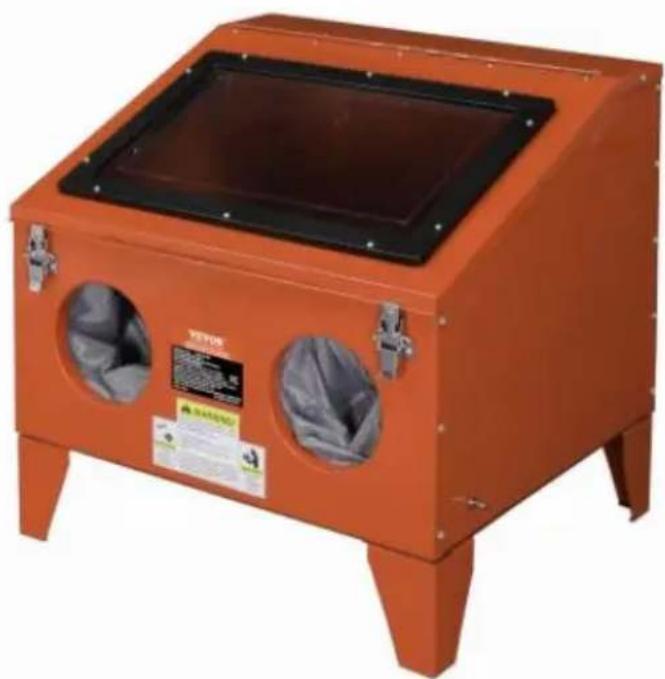
The SBC150 shot blasting cabinet is constructed of steel with double side doors, replaceable viewing screen and internal illumination.
Supplied with a shot blasting gun, the unit is suitable for glass beads, silicon aluminum oxide and silica sand. Excellent for use in a wide variety of works
and body shop cleaning applications. The cabinet requires a standard, clean,
3. OPERATING INSTRUCTIONS
WARNING! Ensure you read, understand and apply safety instructions in section before using the unit.
NOTE! We strongly recommend that a suitable dust extraction system is used with this unit.
If dust extraction is not used, media may be forced out of the joins as pressure builds up. You can alleviate this to some extent by removing the white blanking plug (Fig.1) situated on the upper left corner at the rear of the tank when viewed from the front. This however will not substitute a suitable dust extraction system.
3.1. Connect the air supply to the inlet on the front of the cabinet. Ensure the valve is in the "off" position before connecting the air supply. 3.2. Check all fittings to ensure that there are no air leaks. 3.3. Pour the abrasive media into the centre of the cabinet. DO NOT use more than 10lbs (4.5kg). Excessive amounts of abrasive will impair visibility, create poor blasting performance, and could block the air exhaust. 3.4. Fit a suitably sized jet (33A) and nozzle (33) into the gun bore and retain set screws. The larger the abrasive particles, the larger the jet and nozzle required. 3.5. Plug the transformer into a mains socket and the transformer lead into a socket on the back of the cabinet. 3.6. Place the workpiece in the cabinet and close and latch the door(s) securely. WARNING! Failure to securely close the doors could result in damage and/or personal injury. 3.7. Turn on the light (switch to the left of the viewing window) and air supply, and insert hands into cabinet gloves. Grasp the gun and depress the trigger to start the blasting process. 3.8. Move the blast media (which looks like steam) continuously over the work in an even and circular motion. To avoid undesirable peening, the flow should not be too hard or concentrated. The surface finish may vary from coarse to fine depending on the size of the abrasive media. On delicate workpieces, to avoid unnecessary peening or excessive abrasion, begin blasting with a low air flow.
4. TROUBLESHOOTING
| PROBLEM | POSSIBLE CAUSE | REMEDY |
| Excessive dust in the cabinet. | 1 Exhaust vent or air flow is blocked.2 Abrasive is worn.3 Too much abrasive in cabinet.4 Loose air line or fitting | 1 Clean vent and keep vent a from any wall.Connect to a suitable dust exaction system2 Replace3 Remove excess4 Check and tighten all air fit |
| Uneven blasting. | 1 Too much abrasive in cabinet.2 Moisture inside cabinet | 1 Remove excess2 Check air line for moisture |
| Inadequate speed or efficiency of blast. | 1 Abrasive is worn.2 Pressure is too low | 1 Replace2 Check that there are no sur blockages or leaks Increase pressure. Max;90psi |
| Static electricity. | 1 Dry weather conditions | 1 Leave the work piece to sta for a while |
| Blast pattern too wide or ineffective. | 1 Nozzle blocked or be worn | 1 Unblock or replace nozzle |
5. INSTALLATION INSTRUCTION
Step 1: Assemble the view window
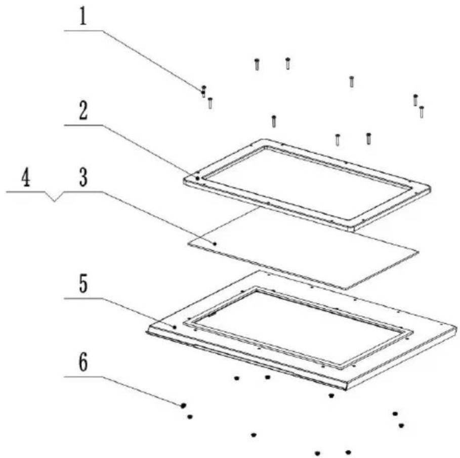
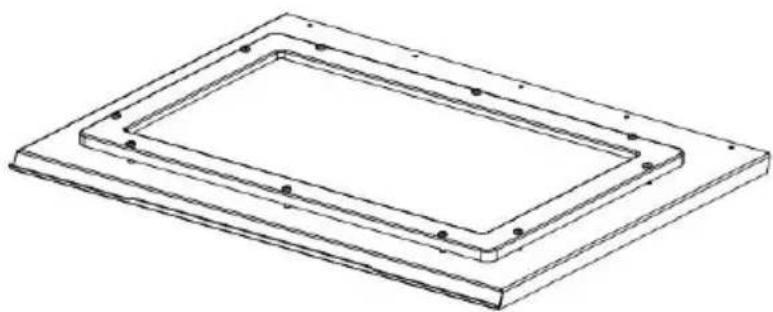
Put the plexiglass (No.3) on the window sheet (No.5), then cover with the plastic frame (No.2). Fix the above 3 parts with cross pan head screws and nuts of M5*25 (No.1 & 6). Please peel the original film off the glass before use.
Please remove the original glass film from the window surface when all assembly is finished.
Step 2: Assemble cabinet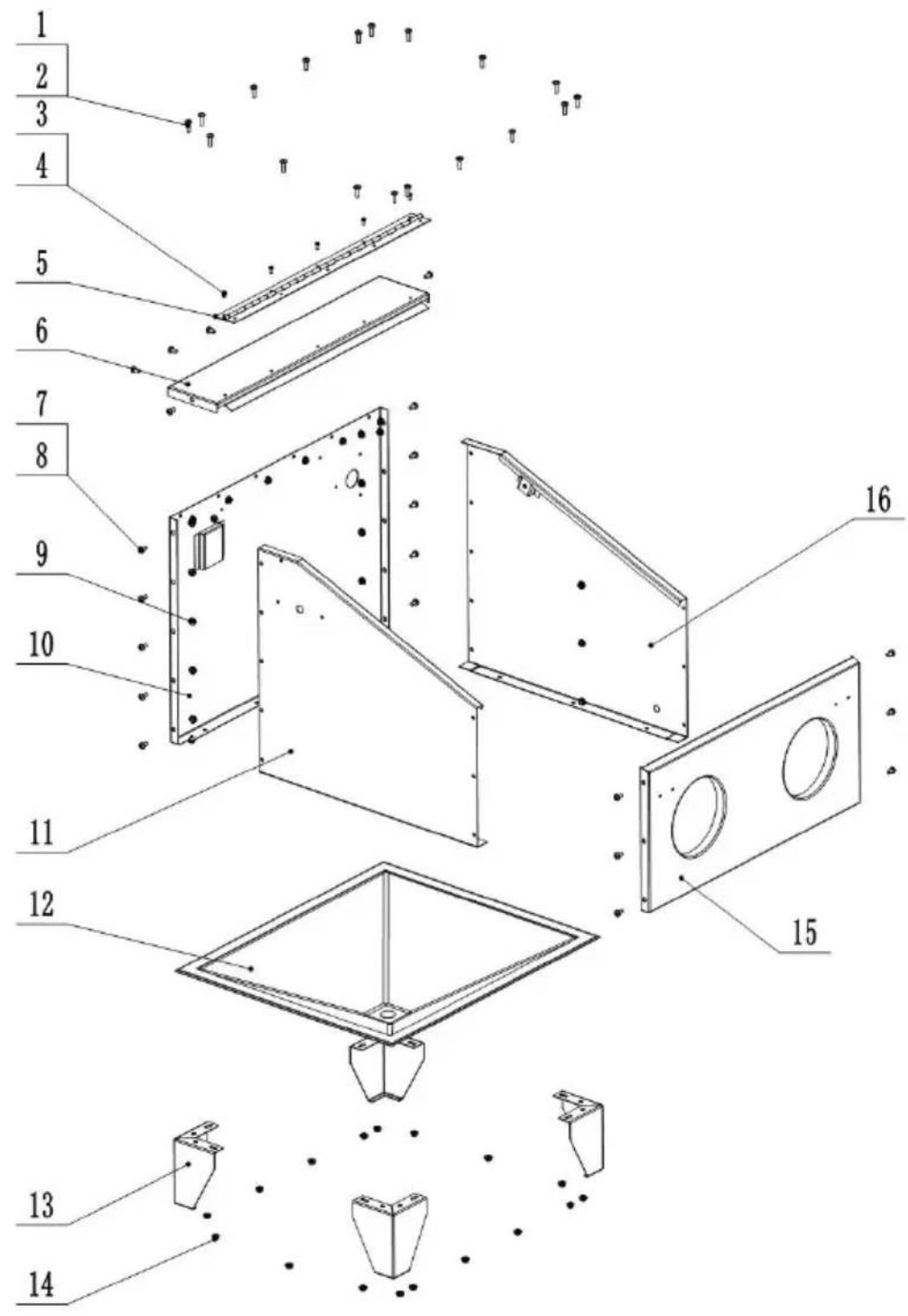
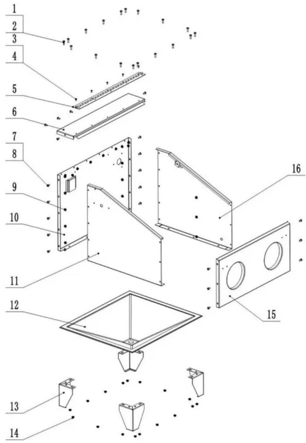
- Connect the left cabinet plate (No.11), right cabinet plate (No.16) with the rear cabinet plate (No.10) using M6*12 screws (No.7), washers (No.8), and nuts (No.8). Connect the front plate (No.15) with the left and right plates. Finally, connect the top plate (No.6) with the other
three plates.
- Fix the hinge (No.5) to the front plate using M4*10 screws (No.3) and nuts (No.4).
- Connect the sand funnel (No.12) and legs (No.13) to the cabinet assembly using M6 screws (No.1), washers (No.2), and nuts (No.14).
- Put the black funnel cover on the funnel bottom.
Note: Please do not tighten each part when assembling; make sure all plates are in the right place.
After all parts are in place,
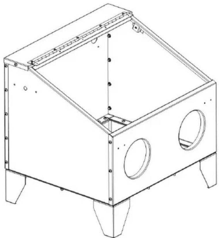
connect all, then tighten the screws.
Step 3: Assemble the blasting gun.
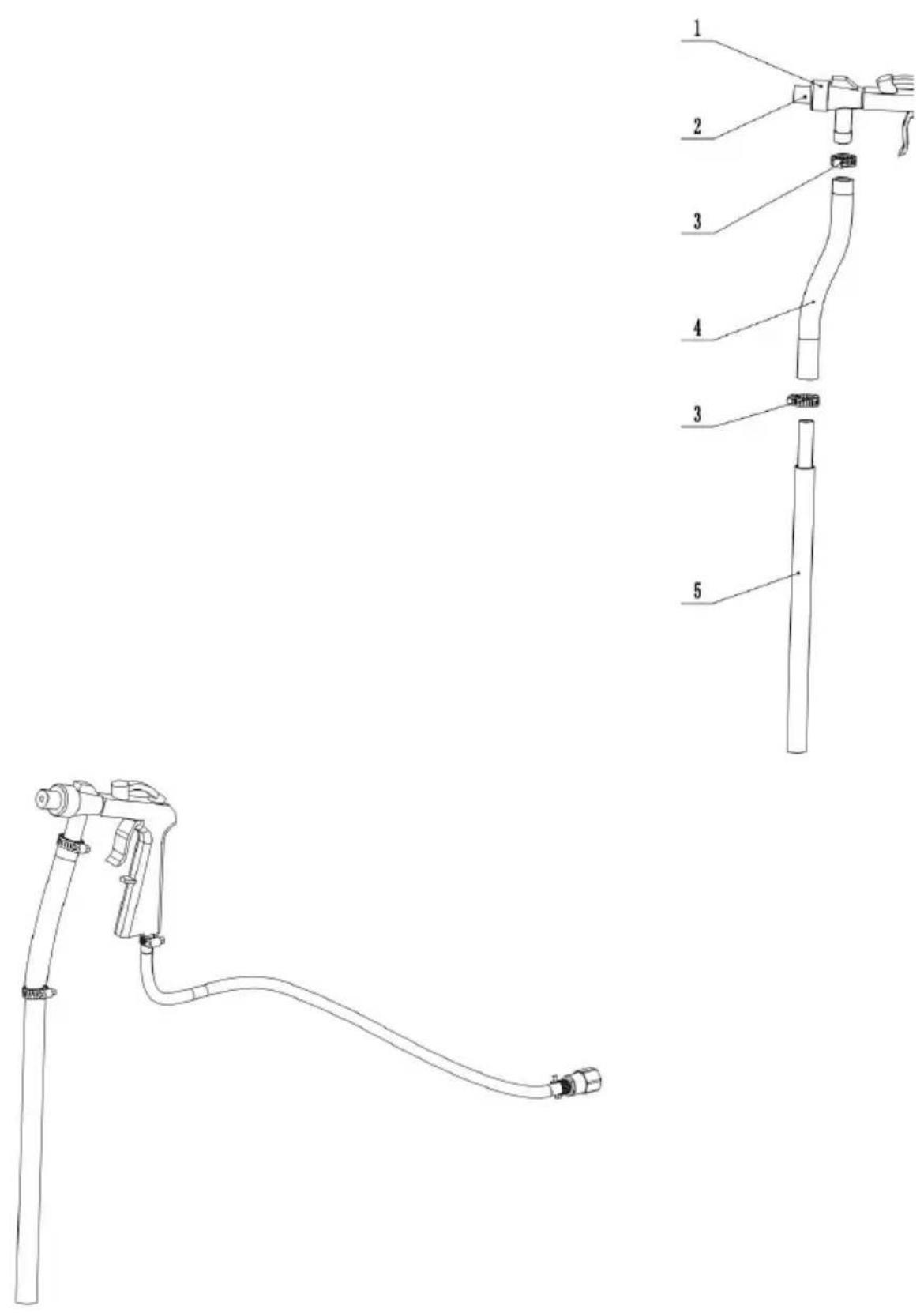
- Connect the sand hose (No. 4) to the gun (No. 2) and clamp it (No. 3). Connect the sand pipe (No. 5) into the sand hose and clamp it tightly.
- Connect the air hose (No. 8) to the gun and clamp it (No. 7). Then connect the air connector (No. 6) and the inner thread connector (No. 9). Wrap 5 circles of Teflon tape clockwise on the air connector to avoid leakage.
Step 4: Assemble the full machine.
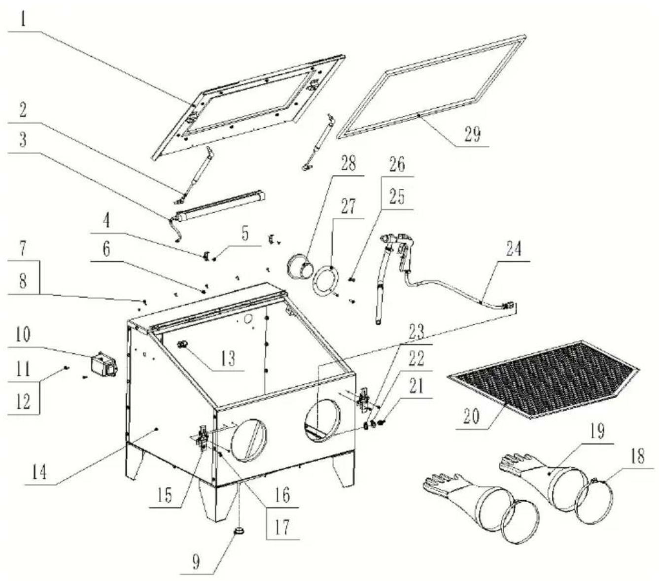
- Put the net (No. 20) into the cabinet (No. 14).
- Put the gun assembly (No. 24) into the cabinet (No. 14), then put the steel washer (No. 22) and rubber washer (No. 23) on the air connector (No. 21) in turn. Wrap 5 circles of Teflon tape clockwise on the joint and connect it with the inner thread connector of the cabinet.
- Assemble the gloves (No. 19), noting that the left and right directions differ, and clamp them (No. 18).
- Assemble the door locker (No. 15) with the front plate using M4*10 screws (No. 16) and nuts (No. 17).
- Put the filter (No. 28) into the filter plate (No. 27) and fix it to the inside of the rear plate using M5*20 screws (No. 25) and nuts (No. 26).
- Assemble the LED lamp (No. 3) with the lamp clips (No. 4) using M4*10 screws (No. 5) and nuts (No. 6).
- Put the lamp wires into the sealing joint (No. 13) and insert it into the left cabinet plate. Tighten the joint. Connect the wire to the switch box (No. 10) and fix the cabinet using M5*10 screws (No. 11) and nuts (No. 12).
- Fix the viewing window (No. 1) to the hinge of the cabinet using M4*10 screws (No. 7) and nuts (No. 8).
- Fix the gas spring (No. 2) to the viewing window and the cabinet.
- Stick the sealing foam around the inside of the viewing window.
- Block the black cover (No.9) on the bottom.
Note:
- The chamfer side of the mesh should be placed on the air intake side of the cabinet, which is convenient for inserting the sand pipe.
- The sealing joint should be unscrewed, then insert the wires and screw a
- The stainless steel parts of the air spring should be downwards.
6. PACKING LIST
| No. | Name | Q'ty | No. | Name | Q'ty |
| 1 | Window plate | 1 | 17 | Hex nut M4 of door | 4 |
| 1-1 | Plexiglass (with 1 film) | 1 | 18 | Glove clamp | 2 |
| 1-2 | Window frame | 1 | 19 | Glove (pair) | 1 |
| 1-3 | Cross pan head screw 8 nut M5*25 | 10 | 20 | Working net | 1 |
| 2 | Gas spring | 2 | 21 | Air connector1/4-∅6 | 1 |
| 3 | Led Lamp | 1 | 22 | Steel washer ∅13 | 1 |
| 4 | Lamp clip | 2 | 23 | Rubber washer ∅12.5 | 1 |
| 5 | Cross countersunk screw M4*16 of lamp clip | 2 | 24 | Blasting gun assembly | 1 |
| 6 | Hex nut M4 of lamp clip | 2 | 24-1 | Air connector1/4-∅6 | 2 |
| 7 | Hinge | 1 | 24-2 | Air hose | 1 |
| 8 | Cross pan head screw & nut M4*10 of hinge | 10 | 24-3 | Inner thread connector 1/4" | 1 |
| 9 | Black funnel cover | 1 | 24-5 | Clamp ∅16-∅25 | 2 |
| 10 | Switch box | 1 | 24-6 | Clamp ∅8-∅12 | 2 |
| 11 | Cross pan head screw M5*10 | 2 | 24-7 | Nozzle (4.5mm) | 1 |
| 12 | Hex nut M5 | 2 | 24-8 | Sand hose | 1 |
| 13 | Sealing joint | 1 | 24-9 | Sand pipe | 1 |
| 14 | Cabinet assembly | 1 | 25 | Cross pan head screw M5*20 | 3 |
| 14-1 | Top cabinet plate | 1 | 26 | Hex flange nut M5 | 3 |
| 14-2 | Front cabinet plate | 1 | 27 | Filter plate | 1 |
| 14-3 | Rear cabinet plate | 1 | 28 | Filter | 1 |
| 14-4 | Left cabinet plate | 1 | 29 | Sealing foam 2.2M | 1 |
| 14-5 | Right cabinet plate | 1 | 31 | Transformer | 1 |
| 14-6 | Cross pan head screw,washer &nut M6*12 | 24 | 32 | Nozzle (5, 6, 7mm) | 3 |
| 14-7 | Leg | 4 | 33 | Plexiglass protective filr | 3 |
| 14-8 | Sand funnel | 1 | 34 | Teflon tape | 1 |
| 14-9 | Cross pan head screw ,washer &nut M6*16 | 18 | 35 | Silicone sealant 50g | 1 |
| 15 | Door lock | 2 | 36 | Manual | 1 |
| 16 | Cross pan head screwM4*10 | 4 |
Important Note:
- Due to logistics reasons, a few metal sheets may become slightly deformed, which can be corrected with simple tools. This is normally easy to do. However, please consult customer service if the correction is still not in place after you try. Customer service staff will provide proper solutions in time.
- The sealing foam can be punctured with a screwdriver before assembly to facilitate the installation of screws (the holes will be hidden by the sealing foam).
7. FCC Information
CAUTION: Changes or modifications not expressly approved by the party responsible for compliance could void the user's authority to operate the equipment!
This device complies with Part 15 of the FCC Rules. Operation is subject to the following two conditions:
1) This product may cause harmful interference. 2) This product must accept any interference received, including interference that may cause undesired operation.
WARNING: Changes or modifications to this product not expressly approved by
the party responsible for compliance could void the user's authority to operate the product.
Note: This product has been tested and found to comply with the limits for a Class B digital device, pursuant to Part 15 of the FCC Rules. These limits are designed to provide reasonable protection against harmful interference in a residential installation.
This product generates, uses, and can radiate radio frequency energy, and if not installed and used in accordance with the instructions, may cause harmful interference to radio communications. However, there is no guarantee that interference will not occur in a particular installation. If this product does cause harmful interference to radio or television reception, which can be determined by turning the product off and on, the user is encouraged to try to correct the interference by one or more of the following measures.
- Reorient or relocate the receiving antenna.
- Increase the distance between the product and the receiver.
- Connect the product to an outlet on a circuit different from that to which the receiver is connected.
- Consult the dealer or an experienced radio/TV technician for assistance.
8. CORRECT DISPOSAL
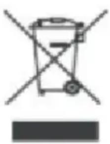
This product is subject to the provisions of European Directive 2012/19/EU. The symbol showing a wheelie bin crossed through indicates that the product requires separate refuse collection in the European Union. This applies to the product and all accessories marked with this symbol. Products marked as such may not be discarded with normal domestic waste, but must be taken to
a collection point for recycling electrical and electronic devices.
Address: Baoshanqu Shuangchenglu 803long 11hao 1602A-1609shi Shanghai
Imported to AUS: Shuangchenglu 803nong11hao1602A-1609shi, baoshanqu, shanghai 200000 CN.
Imported to USA: Sanven Technology Ltd. Suite 250, 9166 Anaheim Place, Rancho Cucamonga, CA 91730
| UK | REP |
YH CONSULTING LIMITED.
C/O YH Consulting Limited Office 147,
Centurion House, London Road,
Staines-upon-Thames, Surrey, TW18 4AX
| EC | REP |
E-CrossStu GmbH.
Mainzer Landstr.69, 60329 Frankfurt am Main
VEVOR®
TOUGH TOOLS, HALF PRICE
Technical Support and E-Warranty Certificate
www.vevor.com/support
VEVOR®
TOUGH TOOLS, HALF PRICE
NEED HELP? CONTACT US!
connect everything
then tighten
screws.
C/O YH Consulting Limited Bureau 147,
Maison Centurion, London Road,
Staines-upon-Thames, Surrey, TW18 4AX
E-CrossStu GmbH.
NEED HELP? CONTACT US!
connect everything
then tight
screw.
C/O YH Consulting Limited Office 147,
Centurion House, London Road,
Staines-upon-Thames, Surrey, TW18 4AX
www.vevor.com/support
VEVOR®
TOUGH TOOLS, HALF PRICE
NEED HELP? CONTACT US!
connect everything
narrow point
screw.
C/O YH Consulting Limited Office 147,
Casa del Centurione, London Road,
Staines-upon-Thames, Surrey, TW18 4AX
| REP.CE |
E-CrossStu GmbH.
Mainzer Landstr.69, 60329 Frankfurt am Main.
VEVOR®
TOUGH TOOLS, HALF PRICE
electronics www.vevor.com/support
VEVOR®
TOUGH TOOLS, HALF PRICE
Step 2 Assemble the cabinet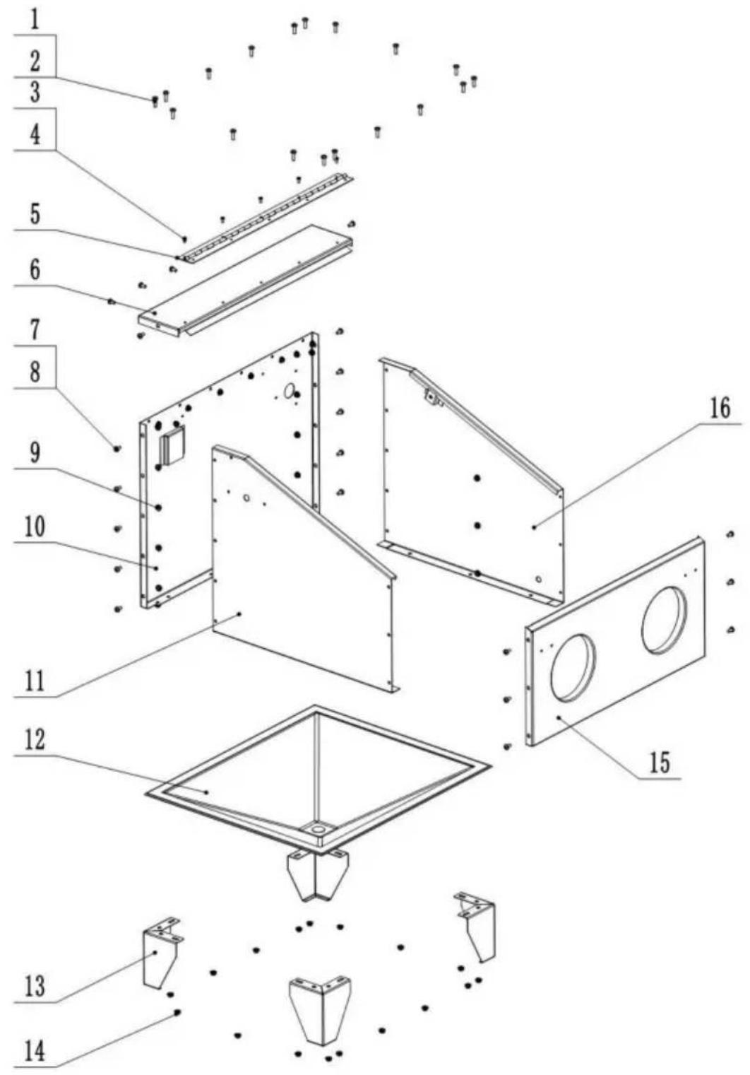
connect everything
Rancho Cucamonga, CA 91730
YH CONSULTING LIMITADO.
C/O YH Consulting Limited Office 147,
Centurion House, London Road,
Staines upon Thames, Surrey, TW18 4AX
E-CrossStu GmbH.
NEED HELP? CONTACT US!
- TROUBLESHOOTING
Step 2 Assemble the cabinet
connect everything
then firmly
screw. each
C/O YH Consulting Limited Office 147,
Centurion House, London Road,
Staines-upon-Thames, Surrey, TW18 4AX
| REPREZENT KE |
E-CrossStu GmbH.
Mainzer Landstr.69, 60329 Frankfurt am Main.
VEVOR®
TOUGH TOOLS, HALF PRICE
www.vevor.com/support
VEVOR®
TOUGH TOOLS, HALF PRICE
Technical support and e-warranty certificate www.vevor.com/support
SANDBLASTING CABINET
MODEL: SBC150
NEED HELP? CONTACT US!
Step 2 Assemble the cabinet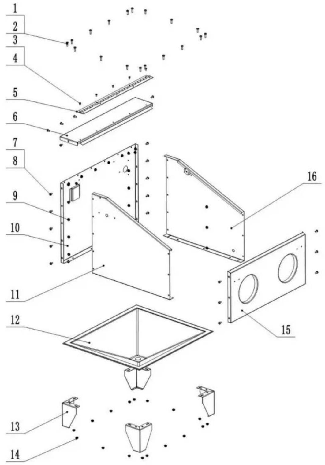
connect everything
then tighten
screw.
C/O YH Consulting Limited Office 147,
Centurion House, London Road,
Staines-upon-Thames, Surrey, TW18 4AX
E-CrossStu GmbH.
Mainzer Landstr.69, 60329 Frankfurt am Main.
VEVOR®
TOUGH TOOLS, HALF PRICE
warranty certificate www.vevor.com/support
VEVOR®
TOUGH TOOLS, HALF PRICE
NEED HELP? CONTACT US!
Step 2 Mount the cabinet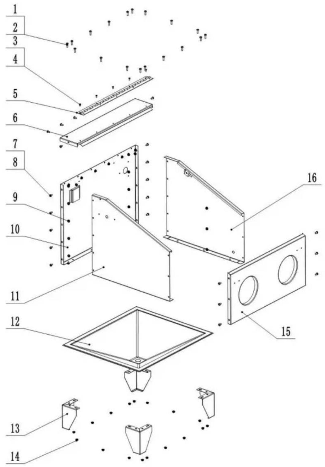
connect all
then tightly
screw.
Step 3 Mount the spray gun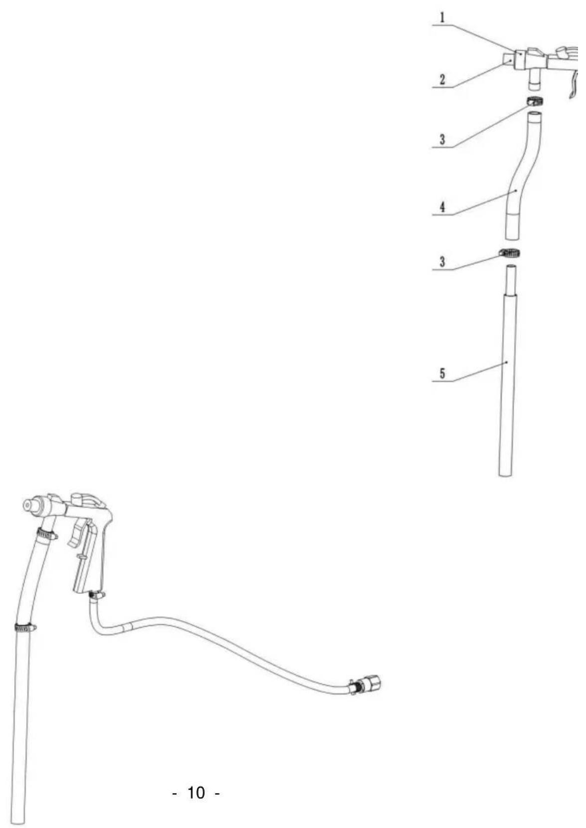
C/O YH Consulting Limited Office 147,
Centurion House, London Road,
Staines-upon-Thames, Surrey, TW18 4AX
| EC | REP |
E-CrossStu GmbH.
Mainzer Landstr.69, 60329 Frankfurt am Main.
VEVOR®
TOUGH TOOLS, HALF PRICE
www.vevor.com/support
- MODEL: SBC
- NEED HELP? CONTACT US
- SAFETY INSTRUCTIONS
- ELECTRICAL SAFETY
- REGARDING DIRECT MAINS POWER USE WITH THE TRANSFORMER PLUG
- GENERAL SAFETY
- DESCRIPTION & SPECIFICATION
- OPERATING INSTRUCTIONS
- TROUBLESHOOTING
- INSTALLATION INSTRUCTION
- STEP 1: ASSEMBLE THE VIEW WINDOW
- STEP 3: ASSEMBLE THE BLASTING GUN
- STEP 4: ASSEMBLE THE FULL MACHINE
- NOTE
- PACKING LIST
- IMPORTANT NOTE
- FCC INFORMATION
- CORRECT DISPOSAL
- VEVOR®
- TOUGH TOOLS, HALF PRICE
- STEP 2 ASSEMBLE THE CABINET
Brand : Vevor
Model : SBC150
Category : Sandblasting cabinet