S1P-HJ2209-120H - Polisher Vevor - Free user manual and instructions
Find the device manual for free S1P-HJ2209-120H Vevor in PDF.

| Product type | Polisher and burnisher |
| Brand | Vevor |
| Model | S1P-HJ2209-120H |
| Rated power | 1300 W |
| No-load speed | 1100 - 3400 rpm |
| Speed settings | 6 positions |
| Polishing wheel size | 120 × 100 mm |
| Brush type | Brass brush |
| Drum inner diameter | 20 mm |
| Power supply | 230 V ~ 50 Hz |
| Protection class | Class II (double insulation) |
| Main functions | Burnishing, polishing, brushing, deburring, rust removal |
| Intended use | Industry and crafts for metals and wood |
| Safety devices | Protective guard, spindle lock, on/off switch |
| Recommended personal protective equipment | Safety glasses, dust mask, hearing protection, gloves |
| Maintenance and cleaning | Regularly clean ventilation slots with dry compressed air |
| Repairability | Technical support and spare parts available via www.vevor.com/support |
| Warranty | Limited warranty on manufacturing defects (see warranty card) |
| General information | Read the manual carefully before use. Follow safety instructions. |
Frequently Asked Questions - S1P-HJ2209-120H Vevor
User questions about S1P-HJ2209-120H Vevor
0 question about this device. Answer the ones you know or ask your own.
Ask a new question about this device
Download the instructions for your Polisher in PDF format for free! Find your manual S1P-HJ2209-120H - Vevor and take your electronic device back in hand. On this page are published all the documents necessary for the use of your device. S1P-HJ2209-120H by Vevor.
USER MANUAL S1P-HJ2209-120H Vevor
Technical Support and E-Warranty Certificate www.vevor.com/support
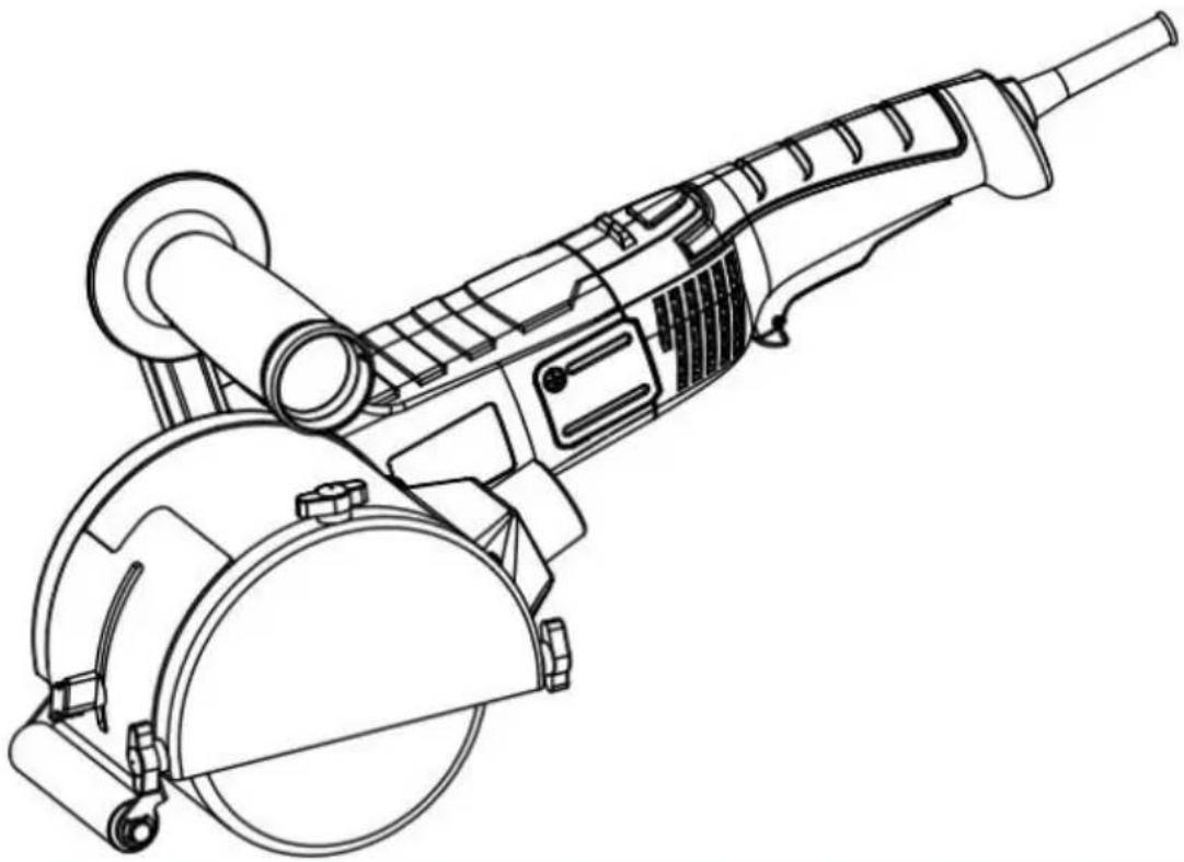
Burnishing Polishing Machine
MODEL: S1P-HJ2209-120H
We continue to be committed to provide you tools with competitive "Save Half", "Half Price" or any other similar expressions used by represents an estimate of savings you might benefit from buying cer with us compared to the major top brands and does not necessarily cover all categories of tools offered by us. You are kindly reminded carefully when you are placing an order with us if you are actually in comparison with the top major brands.
VEVOR®
TOUGH TOOLS, HALF PRICE
Burnishing Polishing Machine
MODEL:S1P-HJ2209-120H
natural_image
Line drawing of a mechanical power tool with a circular base and radial arm (no text or symbols)NEED HELP? CONTACT US!
Have product questions? Need technical support? Please feel from contact us:
Technical Support and E-Warranty Certificate www.vevor.com/support
This is the original instruction, please read all manual instruction carefully before operating. VEVOR reserves a clear interpretation user manual. The appearance of the product shall be subject to product you received. Please forgive us that we won't inform you there are any technology or software updates on our product.
Preface
First of all, let us express our heartfelt thanks to our customers who have purchased our equipment. This manual is for customer service to make better. Written with this equipment. Hope the company's products and services to bring you the canal courtesy.
Important reminder
For your own safety, before assembling and using such products, you must find read this manual to clarify the unique operation, application, and possible problems of this equipment.
This manual is consistent with the date of manufacture of your machine, you find information on the technical data of the machine acquired manual check updates of our machines at the after-service site or related website.
This burnishing machine is designed for:
-Commercial use in industries and trades.
-Surfaces processing such as, for example, burnishing, structuring, polishing, brushing, smoothing, removing rust or burrs from steel or stainless steel or non-metal materials.
-Choose proper wheel when treating wood surfaces.
Specific Safety Instructions
All the safety warnings and instructions included in these instructions will be and followed. Failure to comply with the safety warnings and instructions may result in electrical discharges, fire and/or serious injuries. Keep these instruction for later use.
Take into account all the safety warnings, instructions, pictures and data handed over with this equipment. This electrical tool will be used exclusively following the prescriptions and according to its purpose.
Exclusively use accessories specifically approved by the manufacturer for their use with this electrical tool. The rotation speed of the tool used will be the v indicated on the electronic equipment at the very least. The external dimensions and the thickness of the tool used will correspond to the measurements indicated on the electronic equipment.
The grinding drum and shroud, or other types of accessory, will fit correctly the corresponding spindle of the electrical tool.
Do not use damaged accessories.
Check the application tool before each use in order to determine if it shows detachments or fissures and, in the case of grinding plates, the presence of fissures or excess wear. If the electric tool or the application tool falls to the check to see if they are damaged or directly use an undamaged tool. Once application tool has been checked and is in position, keep yourself and other outside the rotation plane, leaving the equipment running for one minute at maximum speed.
Use personal protection equipment.
Use integral face protection and eye protection (protective glasses) in accordance with the regulations. If necessary, use a dust mask, ear protection (headphone protective gloves, special footwear or an apron that keeps small particles cause by grinding away from your body.
Ensure other persons nearby are outside your work area.
Anyone accessing the work area must be provided the adequate protection equipment.
Do not leave the electrical tool running while moving it from one place to an Regularly clean the ventilation slits of the electrical tool.
Do not use the electrical tool near flammable substances.
Do not use application tools requiring liquid coolants.
Backward movement and corresponding safety measures
Backlash is a sudden reaction to a jammed or blocked processing tool, such as grinding plate, a rotating brush, etc. Jamming of blocking will lead the rotating processing tool to stop suddenly. This causes an uncontrolled acceleration of electrical equipment at the point it became blocked, in the rotation sense opp to that of the tool.
A backlash is the consequence of an improper or inadequate use of the electrical tool. It may be avoided by means of the preventive measures, as described. Hold the electrical tool firmly and place your body and arms in a position all you to offset the backlashes. Should it exist, always use the additional handle order to have a greater control in the case of backlashes or reactions during start-up. The operator can control the backlash or reaction forces by using the appropriate precautionary measures.
Never move your hand close to the application tool while it is rotating. The tool can move onto your hand in the case of a backlash.
Avoid your body from entering the area in which the electronic equipme eventually moves during backlashes.
A backlash pushes the electrical tool in the opposite direction to the movement, the grinding disc at the point where it becomes blocked.
Work taking particular care near corners, sharp tubes, etc.
Avoid the tool bouncing off the piece being processed and becoming jammed. The rc application tool tends to get jammed on corners, sharp edges or when bouncing off piece being processed. This leads to a loss of control or a backlash.
Special safety indications for roughing
Exclusively use approved roughing elements for this electrical tool with its corresponding protection cover. Roughing elements not approved for this electric
tool cannot be covered adequately therefore not being safe.
The protection cover will be firmly assembled on the electrical tool and adjust such a way maximum safety is achieved. That is to say, the smallest portion uncovered grinding agent will be facing the operator. The protection cover has task of protecting the operator from bit becoming detached and from any event contact with the grinding element.
The grinding elements will be used exclusively for their designated uses.
Part-off or roughing discs will not be used in this electrical tool.
Other safety indications
Always hold the electrical tool with both hands on the corresponding surfaces (motor casing and handle).
Hold smaller pieces to be processed in order to avoid their involuntary displacement.
The power supply network voltage and the voltage indications on the characteristics plate must coincide.
SYMBOLS USED

DANGER: This indicates an imminent danger. In the case of non-compliance you will be at risk of death or very serious injuries.

CAUTION: This indicates a situation that is possibly dangerous. Non-compliance implies the risk of injuries or material damages.

Wear hearing protection Wear eye protection

Wear breathing protection Wear hand protection

Read instruction manual

Class II construction (double insulated for additional protection)
Correct Disposal
This product is subject to the provision of european Directive 2012/19. The symbol showing a wheelie bin crossed through indicates that the product requires separate refuse collection in the European Union.
applies to the product and all accessories marked with this symbol. Products marked as such may not be discarded with normal domestic waste, but must taken to a collection point for recycling electrical and electronic devices.
Technical parameter
| Product Name | Burnishing Polishing Machine |
| Model | S1P-HJ2209-120H |
| Rated power | 1300W |
| speed | 1100-3400r/min |
| Gear position | 6 |
| Polishing wheel size | 120 × 100mm |
| Polishing brush type | Brass brush |
Start-up Instructions
Illustrated explanation
- Switch 2. Brush cover 3. Speed controller
- Ventilation grilles 5. Handle 6. Protective Housing
- Disc/Drum/wheel (optional) 8. Cable
- Gear head 10. Spindle lock button
* The accessories described and illustrated do not correspond to the serial material included. The complete range of optional accessories is detailed in our accessory programme.
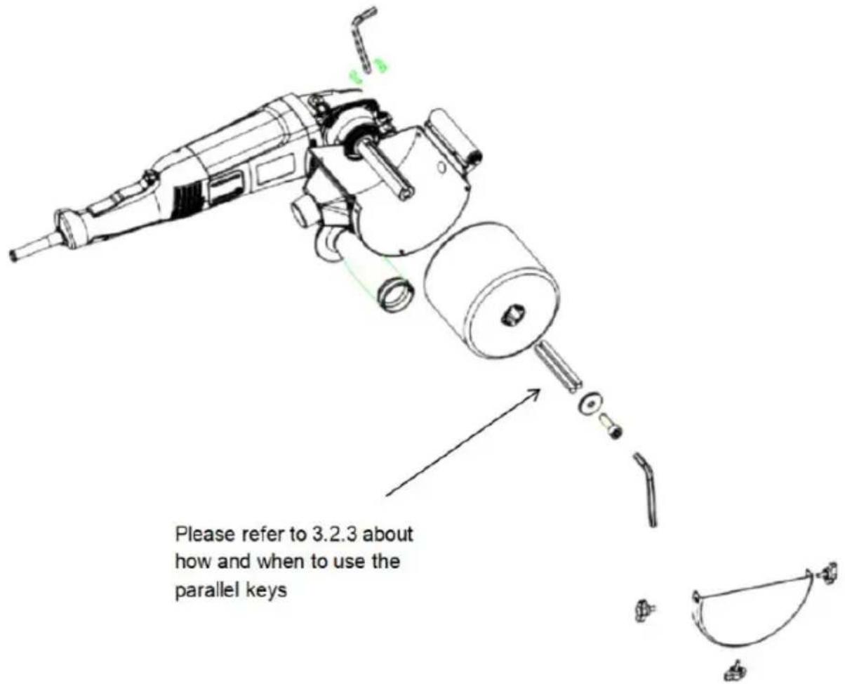
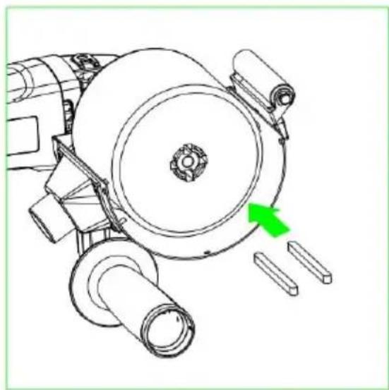
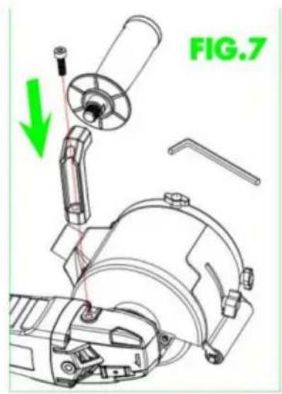
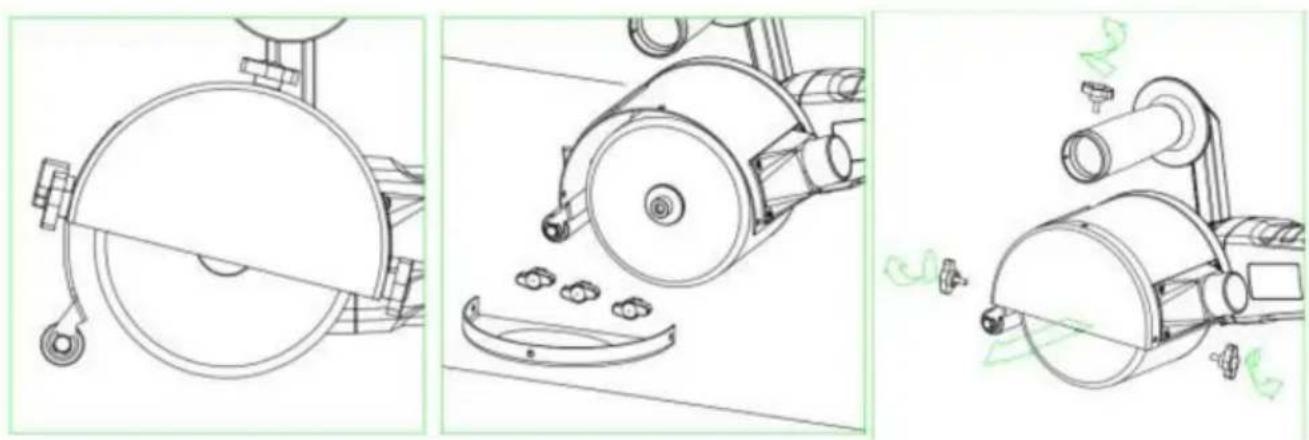
How to assemble and disassemble
natural_image
Technical line drawing of a mechanical component with a circular cross-section and hanging hook (no text or symbols)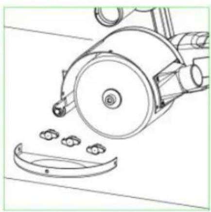
natural_image
Technical line drawing of a mechanical device with a circular component and three small components, no text or symbols present.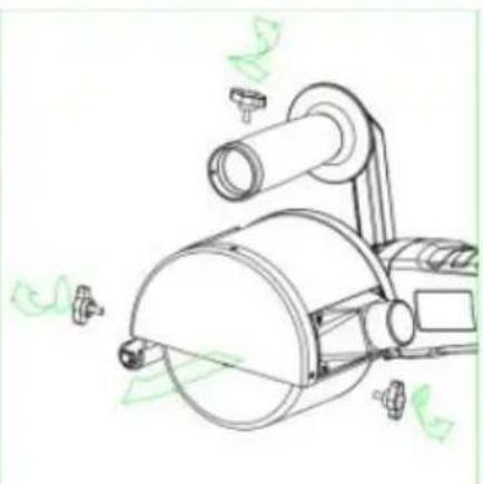
natural_image
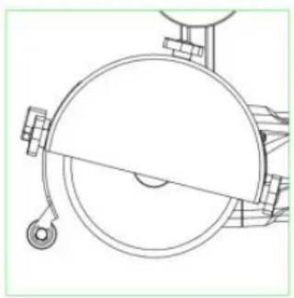
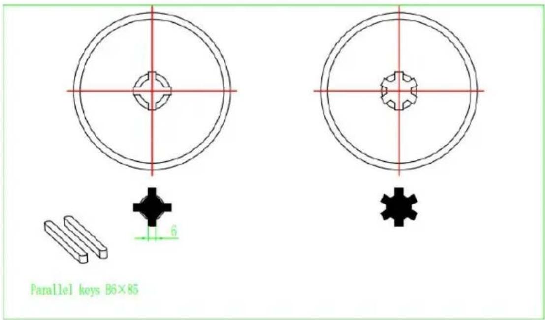
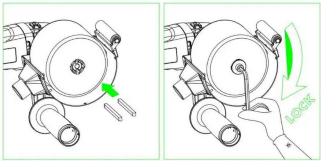
Technical line drawing of a mechanical device with no visible text or symbolsParallel keys :
The machine is suitable with different shaped drum with inner diameter 20mm. When the drum brush is like the ones below, please use the two parallel key fix.
natural_image
Technical line drawing of a mechanical assembly with no visible text or symbols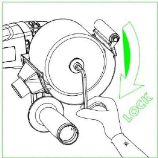
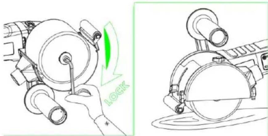
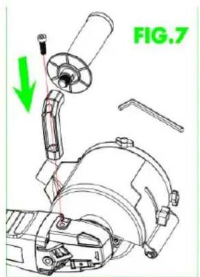
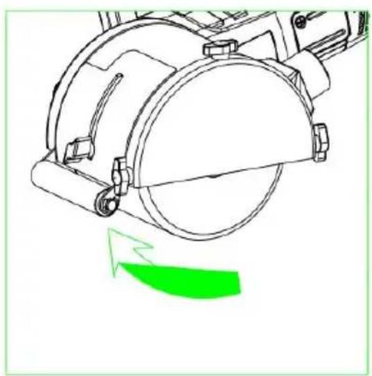
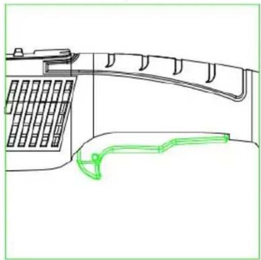
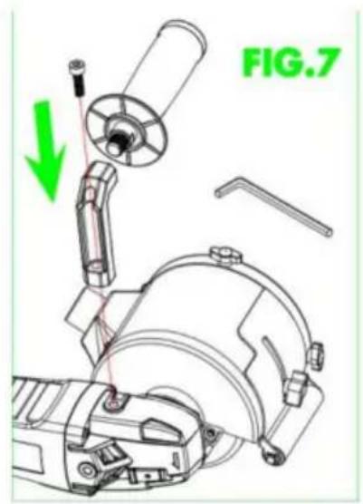
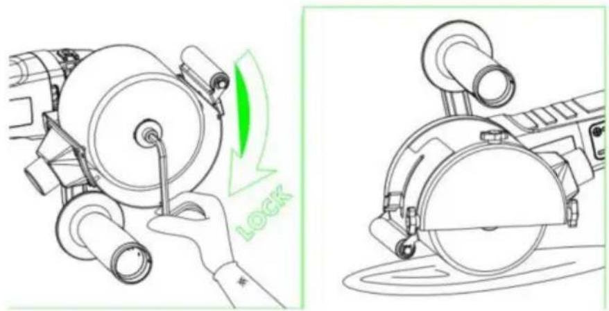
Height Adjustment of the guard
natural_image
Technical line drawing of a mechanical component with a green arrow indicating motion or force direction (no text or symbols)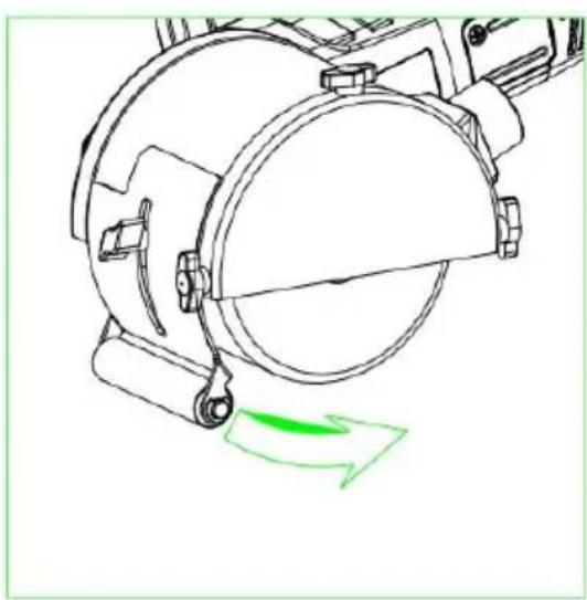
natural_image
Technical line drawing of a mechanical device with a green arrow indicating motion or force (no text or symbols)Operating Instructions
1. Start-up
Disconnect the power supply plug before performing any work in the electric equipment.
Prior to start-up
Unpack the electrical tool and check the volume handed over is complete and determine if any damage occurred during its transport.
-Press switch, keeping it pressed down.
-if you want to stop the tool, release switch.
natural_image
Technical line drawing of a telephone handset and antenna (no text or symbols)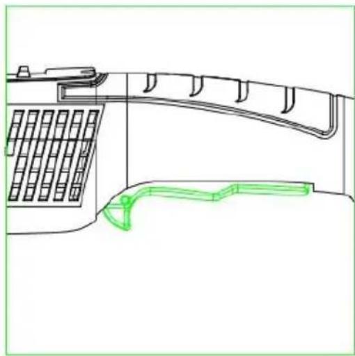
natural_image
Technical line drawing of a mechanical component with grid pattern and curved green outline (no text or symbols)Rotation speed controller
-To adjust the working speed, turn speed controller wheel to the required val Hold the tool or the tool support
-Disconnect the plug from the power supply.
-Press the spindle blocking button and keep it pressed down.
-Loosen the screws with wrench and remove both discs.
- Move the tool or the corresponding support over the tool holder (position adjustment, key).
2. Tool Change
Gear
Do not loosen the screws at the gear head during the guarantee period. Non-compliance will lead to expiry of the manufacturer's guarantee.
3. Adjustment Operation
Protection cover adjustment
The burnishing machine will always be used with the protection cover in plac
-1. Loosen cover adjustment screw
-2. Adjust the protection cover in a position that is appropriate for the task to performed and in the corresponding work position
- Adjust screw once more.
- Adjust the depth
4. General Use Instructions
Once turned off, the grinding tool continues working briefly due to inertia.
Processing of flat surfaces
- Hold the electrical tool with both hands.
- For a decorative finishing of the surface:
- Carefully base the electrical tool on the surface to be processed, performing straight-line movement forward and then back.
Maintenance and Cleaning Instructions
Disconnect the power supply plug before performing any work in the electric equipment.
Cleaning
Conducting dust may be deposited inside the casing when processing metals.
This may have an influence on the protection insulation!
Start the machine using a differential circuit breaker (maximum operating current 30 mA)
Regularly clean the equipment and the ventilation slits Cleaning frequency will depend on the material and the intensity of use.
Periodically clean the lower part of the casing and the motor with dry compr air.
1. Repair Service
The technical service will advise you on any query you may have regarding and maintenance of your product, while also on spare parts. The diagrams for taking apart and the information on spare parts are available at the service: Our team of technical adviser will be pleased to guide you regarding the acquisition, application and adjustment of the products and accessories.
2. Guarantee
Guarantee Card
You may find the guarantee card among the documents included with the electronic tool. The guarantee card must be filled in completely attaching to it a copy purchase receipt or bill and handing it in to the retailer in exchange for an acknowledgment of receipt.
NOTE! Request this card immediately from your retailer if it is missing.
The guarantee is exclusively limited to manufacturing or machining defects, expiring whenever the pieces are disassembled, handled or repaired outside the factory.
3. Elimination
We recommend electrical tools, accessories and packaging are subjected to a recycling process which respects the environment.
Only for EU countries:
Do not throw electrical tools into the rubbish!
In accordance with European Directive 2002/96/EC on waste electrical and electronic equipment, after its transposition into a national law, electrical tools be accumulated separately to be subjected to ecological recycling.
It could significantly increase the oscillation load during the entire period. The during which the equipment is at a halt or, otherwise, the time during which not really worked while being in operation, will also be taken into account to determine the vibration loads. This may significantly reduce the oscillation load during the entire working period.
Implement additional safety measures for operator protection before determining the oscillations, for example: the maintenance of electrical and application tools keeping hands warm, work sequence organization.
Manufacturer: Shanghaimuxinmuyeyouxiangongsi
Address: Shuangchenglu 803nong11hao1602A-1609shi, baoshanqu, shanghai 200000 CN.
Imported to AUS: SIHAO PTY LTD. 1 ROKEVA STREETEASTWOOD NSW 2 Australia
Imported to USA: Sanven Technology Ltd. Suite 250, 9166 Anaheim Place, Rancho Cucamonga, CA 91730
| UK | REP |
YH CONSULTING LIMITED.
C/O YH Consulting Limited Office 147,
Centurion House, London Road,
Staines-upon-Thames, Surrey, TW18 4AX
| EC | REP |
E-CrossStu GmbH
Mainzer Landstr.69, 60329 Frankfurt am Ma
VEVOR®
TOUGH TOOLS, HALF PRICE
Technical Support and E-Warranty Certificate
www.vevor.com/support
VEVOR®
TOUGH TOOLS, HALF PRICE
natural_image
Line drawing of a mechanical power tool with a circular base and radial blade (no text or symbols)BESOIN D'AIDE? CONTACTEZ-NOUS!


natural_image
Three technical line drawings of mechanical components, showing a wheel cutter, gear shift, and a cylindrical device with green annotation lines (no text or symbols)
natural_image
Technical line drawing of a mechanical device with green directional arrows indicating motion (no text or symbols)Mode d'emploi
1. Démarrage
natural_image
Technical line drawing of a mechanical component with grid pattern and curved green outline (no text or symbols)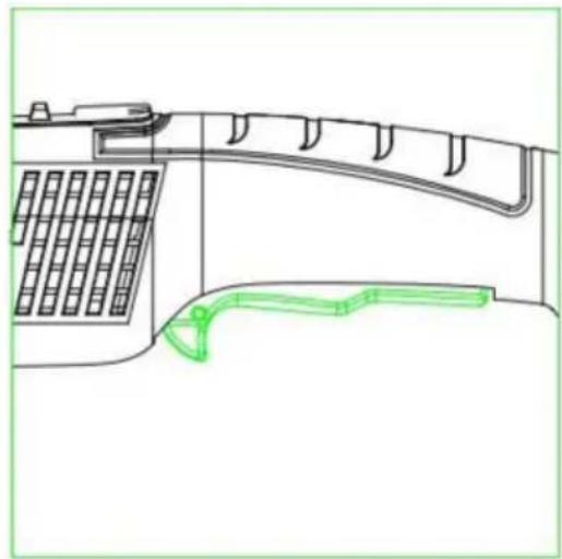
natural_image
Technical line drawing of a mechanical component with grid and curved structure (no text or symbols)C/O YH Consulting Limited Bureau 147,
Staines-upon-Thames, Surrey, TW18 4AX
E-CrossStu GmbH
natural_image
Line drawing of a mechanical power tool with a circular base and radial blade (no text or symbols)

natural_image
Three technical line drawings of mechanical components, showing a wheel cutter, gear shift, and a cylindrical device (no text or symbols present)Passfedern:

natural_image
Technical line drawing of a mechanical device with green directional arrows indicating motion (no text or symbols)Bedienungsanleitung
1. Inbetriebnahme
natural_image
Technical line drawing of a mechanical component with grid and curved features (no text or symbols)
natural_image
Technical line drawing of a mechanical component with grid and curved structure (no text or symbols)Drehzahlregler
C/O YH Consulting Limited Office 147,
Centurion House, London Road,
Staines-upon-Thames, Surrey, TW18 4AX
www.vevor.com/support
VEVOR®
TOUGH TOOLS, HALF PRICE
natural_image
Line drawing of a mechanical power tool with a circular base and radial blade (no text or symbols)


natural_image
Three technical line drawings of mechanical components, showing a wheel cutter, gear shift, and a cylindrical device (no text or symbols)Chiavi parallele:

natural_image
Technical line drawing of a mechanical device with green directional arrows indicating motion (no text or symbols)natural_image
Technical line drawing of a mechanical component with grid and curved features (no text or symbols)
natural_image
Technical line drawing of a telephone handset and antenna (no text or symbols)Importato in AUS: SIHAO PTY LTD. 1 ROKEVA STREETEASTWOOD NSW 2122 Australia
Importato negli USA: Sanven Technology Ltd. Suite 250, 9166 Anaheim Place, Rancho Cucamonga, CA 91730
CONSULENZA YH LIMITATA.
C/O YH Consulting Limited Ufficio 147,
Casa del centurione, London Road,
Staines-upon-Thames, Surrey, TW18 4AX
elettronica www.vevor.com/support
VEVOR®
TOUGH TOOLS, HALF PRICE
natural_image
Line drawing of a mechanical power tool with a circular base and radial blade (no text or symbols)


natural_image
Three technical line drawings of mechanical components, showing a wheel cutter, fan blade, and cylindrical device (no text or symbols)Claves paralelas:

natural_image
Technical line drawing of a mechanical device with green directional arrows indicating motion (no text or symbols)natural_image
Technical line drawing of a mechanical device with grid and handle components (no text or symbols)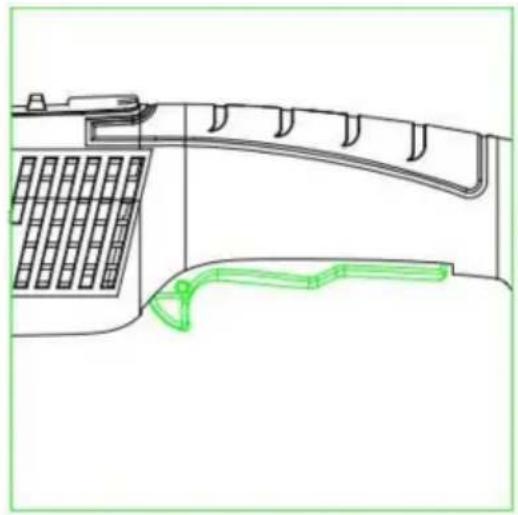
natural_image
Technical line drawing of a mechanical device with grid and curved components, no text or symbols presentCasa Centurión, London Road,
Staines-upon-Thames, Surrey, TW18 4AX

E-CrossStu GmbH
natural_image
Line drawing of a mechanical power tool with a circular base and radial blade (no text or symbols)POTRZEBUJESZ POMOCY? SKONTAKTUJ SIĘ Z NAMI!


natural_image
Three technical line drawings of mechanical components, showing a wheel cutter, fan blade, and cylindrical device (no text or symbols)Klucze równoległe:
natural_image
Technical line drawing of a mechanical device with green directional arrows indicating motion (no text or symbols)Instrukcja obsługi
1. Uruchomienie
natural_image
Line drawing of a telephone handset and cable connector (no text or symbols)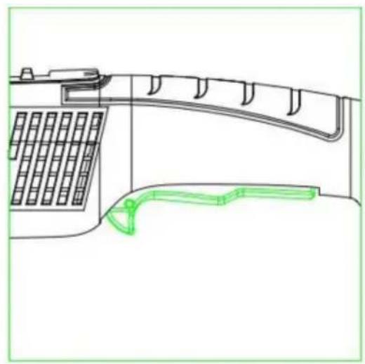
natural_image
Technical line drawing of a mechanical component with grid pattern and curved green outline (no text or symbols)C/O YH Consulting Limited Biuro 147,
Dom Centuriona, London Road,
Staines-upon-Thames, Surrey, TW18 4AX
| Przedstawiciel UE |
E-CrossStu GmbH
Mainzer Landstr.69, 60329 Frankfurt nad Menem.
VEVOR®
TOUGH TOOLS, HALF PRICE
natural_image
Line drawing of a mechanical power tool with a circular base and radial blade (no text or symbols)HULP NODIG? NEEM CONTACT MET ONS OP!


natural_image
Three technical line drawings of mechanical components, showing a wheel cutter, fan blade, and cylindrical device (no text or symbols)Parallelle toetsen:

natural_image
Technical line drawing of a mechanical device with green directional arrows indicating motion (no text or symbols)Gebruiksaanwijzing
1. Opstarten
natural_image
Technical line drawing of a mechanical device with grid and handle components (no text or symbols)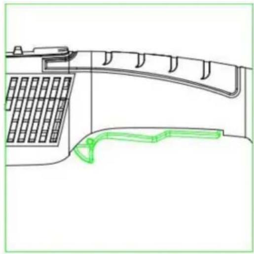
natural_image
Technical line drawing of a mechanical component with grid and curved structure (no text or symbols)C/O YH Consulting Limited Kantoor 147,
Centurionhuis, Londen Road,
Staines-upon-Thames, Surrey, TW18 4AX

E-CrossStu GmbH
Mainzer Landstr.69, 60329 Frankfurt am Main.
VEVOR®
TOUGH TOOLS, HALF PRICE
garantiecertificaat www.vevor.com/support
VEVOR®
TOUGH TOOLS, HALF PRICE
natural_image
Line drawing of a mechanical power tool with a circular base and radial blade (no text or symbols)BEHÖVER HJÄLP? KONTAKTA OSS!


natural_image
Three technical line drawings of mechanical components, showing a wheel cutter, a disc, and a device with green arrows indicating motion (no text or symbols)Parallella tangenter:

natural_image
Technical line drawing of a mechanical device with green directional arrows indicating motion (no text or symbols)Bruksanvisning
1. Uppstart
natural_image
Line drawing of a mechanical device with grid and curved green outline (no text or symbols)
natural_image
Technical line drawing of a mechanical device with grid and curved components, no text or symbols presentRotationshastighetsregulator
1. Reparationsservice
C/O YH Consulting Limited Office 147,
Centurion House, London Road,
Staines-upon-Thames, Surrey, TW18 4AX
| EC | REP |
E-CrossStu GmbH
Mainzer Landstr.69, 60329 Frankfurt am Main.
VEVOR®
TOUGH TOOLS, HALF PRICE
www.vevor.com/support