FF-Q903 - Polisher Vevor - Free user manual and instructions
Find the device manual for free FF-Q903 Vevor in PDF.

| Product Type | Abrasive Sandblaster with Pressure Pot |
| Brand | Vevor |
| Model | FF-Q903 |
| Tank Volume | 20 gallons (approx. 75.7 L) |
| Suggested Abrasive Capacity | 33 L |
| Working Pressure | 60-110 psi (max 125 psi) |
| Air Consumption | 6-25 CFM |
| Power Source | Compressed Air |
| Recommended Air Hose | 1/2 in minimum inner diameter |
| Main Functions | Paint stripping, rust removal, metal surface cleaning, surface preparation |
| Compatible Abrasive Materials | Sand (not recommended), Black Beauty, steel shot, glass beads, aluminum oxide, plastic pellets |
| Safety | Wear safety glasses, hearing protection, gloves, NIOSH-approved respirator; do not exceed 125 psi |
| Maintenance | Drain compressor, clean filter, check seals, replace worn nozzles, inspect abrasive hose |
| Spare Parts | Ceramic nozzles, abrasive hose, urethane seals, valves, adapters, clamps |
| Repairability | Parts replaceable by a qualified technician; use original replacement parts |
| Dimensions (approx.) | Not specified in the manual |
| Weight (approx.) | Not specified in the manual |
| Warranty | Electronic warranty certificate available at www.vevor.com/support |
| General Information | Made in China; imported by various representatives (EU, UK, AU, US) |
Frequently Asked Questions - FF-Q903 Vevor
User questions about FF-Q903 Vevor
0 question about this device. Answer the ones you know or ask your own.
Ask a new question about this device
Download the instructions for your Polisher in PDF format for free! Find your manual FF-Q903 - Vevor and take your electronic device back in hand. On this page are published all the documents necessary for the use of your device. FF-Q903 by Vevor.
USER MANUAL FF-Q903 Vevor
Technical Support and E-Warranty Certificate www.vevor.com/support
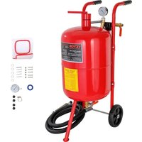
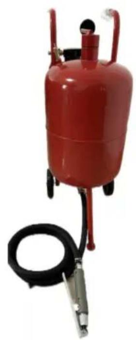
ABRASIVE BLASTER TANK
MODEL: FF-Q903
We continue to be committed to provide you tools with competitive price. "Save Half", "Half Price" or any other similar expressions used by us only repressor estimate of savings you might benefit from buying certain tools with us compared to top brands and does not necessarily mean to cover all categories of tools offered by are kindly reminded to verify carefully when you are placing an order with us if yo actually saving half in comparison with the top major brands.
MODEL: FF-Q903
natural_image
Red industrial pressure vessel with attached black hose and metal fittings (no visible text or symbols)NEED HELP? CONTACT US!
Have product questions? Need technical support? Please feel free contact us:
Technical Support and E-Warranty Certificate www. vevor. com/support
This is the original instruction, please read all manual instructions carefully before operating. VEVOR reserves a clear interpretation of user manual. The appearance of the product shall be subject to the product you received. Please forgive us that we won't inform you if there are any technology or software updates on our product.
 | Warning-To reduce the risk of injury, user must read instructions manual carefully. |
 | Always wear ANSI approved safety goggles when working with tools and equipment. |
 | Wear eye protection. |
 | Wear ear protection. Wear protective gloves. |
 | Compliance is a EC & UK security certification. |
Safety Warnings and Precautions
Thank you for using this product. In order to make sure that you can operate the machine correctly, read this instruction carefully before operation and keep it properly for future reference. Please be sure to read the precautions and safety rules in this page to ensure your safe use. This manual will outline safety warning and precautions, operating, maintenance and cleaning. The warnings and instructions reviewed in this manual cannot cover all possible conditions and situations that may occur. Caution and common sense are not built into this product, since we believe that the uses will comply with these codes.
Please read ALL the instructions before using your machine.
- Keep work area clean. Cluttered areas invite injuries.
- Observe work area conditions. Do not use machines in damp or wet locati Don't expose to rain. Keep work area well lighted. Do not use product in the presence of flammable gasses or liquids.
- Keep children away. Children must never be allowed in the work area, Do let them handle machines, tools, or extension cords.
-
Store idle equipment. When not in use, tools must be stored in a dry locat to inhibit rust. Always lock up tools and keep out of reach of children.
-
Use the right tool for the job. Do not attempt to force a small tool or attachment to do the work of a larger industrial tool. There are certain application for which this tool was designed. It will do the job better and more safely at the for which it was intended. Do not modify this tool and do not use this tool for a purpose for which it was not intended.
- Dress properly. Do not wear loose clothing or jewelry as they can be caught in moving parts.
Protective, electrically non-conductive clothes and no-skid footwear are recommended when working. Wear restrictive hair covering to contain long hair.
- Use eye and ear protection. Always wear ANSI approved impact safety goggles.
- Maintain tools with care. Inspect tool cords periodically and if damaged, have them repaired by an authorized technician. The handles must be kept clean, dry, and free from oil and grease at all times. Please power off and unplug before maintenance and cleaning.
- Avoid unintentional starting. Please turn off the air source when not in use.
- Stay alert. Watch what you are doing, use common sense. Do not operate any tool when you are tired.
- Check for damaged parts. Before using any tool, any part that appears damaged should be carefully checked to determine that it will operate properly and perform its intended function. Check for alignment and binding of moving parts; any broken parts or mounting fixtures; and any other condition that may affect proper operation. Any part that is damaged should be properly repaired or replaced by a qualified technician. Do not use the tool if any switch does not turn On and Off properly.
- Replacement parts and accessories. When servicing, use only identical replacement parts. Use of any other parts will void the warranty. Only use accessories intended for use with tool.
- Do not operate tool if under the influence of alcohol or drugs. Read warning labels on prescriptions to determine if your judgment or reflexes are impaired while taking drugs. If there is any doubt, do not operate the tool.
-
Maintenance. For your safety, maintenance should be performed regularly by a qualified technician.
-
Never use the machine around flammable materials.
- Do NOT immerse the appliance in water or any other liquid.
- This product cannot be used for other purposes. Not suitable for commercial use. INDOOR USE ONLY.
- Do not use alcohol, gasoline, etc. as coolant.
- Keep bystanders a safe distance away from work area. Anyone enter the work area must wear personal protective equipment. Fragments of work piece or of a broken accessory may fly away and cause injury beyond immediate area of operation.
- This appliance is not intended for use by young or infirm persons unless supervised by a responsible person to ensure that they can use the appliance safely. Young children should be supervised to ensure that they do not play with the appliance. Children and pets should stay away from the product.
- DO NOT CLEAN IT WITH ANY ABRASIVE MATERIAL.
- Never leave it unattended while in use.
Warning: The warnings, cautions, and instructions discussed in this instruction discussed in this instruction manual cannot cover all possible conditions and situations that may occur. It must be understood by the operator that common sense and caution are factors which cannot be into this product, but must be supplied by the operator of the tool.
HEALTH RISK WARNING
WARNING!
Do not use an ALLSOURCE Pressure Blaster until you have read this manual and you understand its contents and warnings. These warnings are included for the health and safety of the operator and those in the immediate vicinity. Keep this manual for future reference.
Dust created by power sanding, sawing, grinding, drilling, and other construction activities may contain chemical known to cause cancer, birth defects of other reproductive harm and respiratory illnesses. Some examples of the chemicals include:
- Lead from lead based paints
- Crystalline silica from bricks, cement and other masonry products Arsenic and chromium from chemically-treated lumber
Your risk from these exposures varies, depending on how often you do this type of work. To reduce your exposure to these chemicals: Work in a ventilated area, and work with approved safety equipment, such as those dust masks that are specially designed to filter out microscopic particles.
Abrasive blasting produces harmful dust. Everyone in the blasting area must wear a properly fitted and properly maintained NIOSH-approved supplied-air respirator.
SILICOSIS AND OTHER DUSTWARNINGS:
Breathing dust from silica sand may cause silicosis, a fatal lung disease. Breathing dust during blasting operations may also cause asbestosis and/or other serious or fatal diseases. A NIOSH-approved, well-maintained air-supplied abrasive blasting respirator must be used by anyone blasting, anyone handling or using media containing toxic substances or media with more than point point one percent crystalline silica and anyone in the area of the dust. Harmful dust can remain suspended in the air for long periods of time after blasting has ceased, causing serious injury or death.
Before removing respirator, use an air monitoring instrument to determine atmosphere is safe to breathe. Contact local OHSA or NIOSH office to determine the proper respirator for your particular application.
Supplied-Air respirators do not remove or protect against carbon monoxide (CO) or any other toxic gas. Use a carbon monoxide removal device and monitoring device with the respirator to ensure grade D quality air. Follow all applicable OSHA standards and OSHA regulation 1910.134 (d).
SAVE THESE INSTRUCTIONS
You will need these instructions for the safety instructions, the operating procedures, the parts list and the warranty. Put them in a safe and dry place for future reference.
IMPORTANT SAFETY INSTRUCTIONS
WARNING: When using tools such as your air compressor, whether powered by electric motor or gasoline engine, basic safety precautions should always be followed to reduce the risk of fire, electric shock, and personal injury. You should review the safety instructions for your air compressor before beginning abrasive blasting with this tool.
PRODUCT PARAMETERS
| Tank Volume | 20 gallon |
| Working Pressure | 60-110 PSI |
| Air Consumption: | 6-25cfm |
| Suggested abrasive capacity: | 33 L |
Attention:
- Do not use accessories which are not specifically designed and recommended by the tool manufacturer.
- Drain the water from the air compressor before use to ensure the air is dry and avoid abrasive (media) clumping, otherwise it will not work.
- One of the ceramic nozzles has been installed on the product.
PARTS LIST
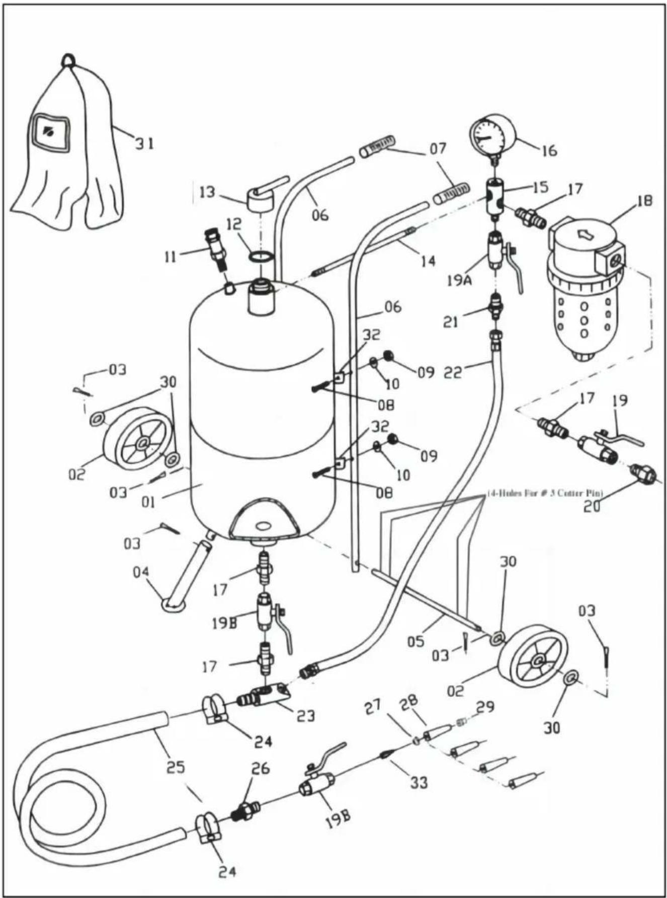
| PARTS LIST | |||||
| PART | DESCRIPTION | QTY | PART | DESCRIPTION | QTY |
| 01 | TANK | 1 | 18 | WATER TRAP FILTER | 1 |
| 02 | WHEELS | 2 | 19 | BRASS AIR SUPPLY VALVE,3/8" | 1 |
| 03 | COTTER PINS | 5 | 19A | BRASS THROTTING VALVE,3/8" | 1 |
| 04 | FOOT | 1 | 19B | BRASS ABRASIVE METERING VALVE,3/8" | 2 |
| 05 | AXLE | 1 | 20 | MALE-FEMALE CONNECTOR | 1 |
| 06 | HANDEBARS | 2 | 21 | NIPPLE CONNECTOR | 1 |
| 07 | HANDLE GRIPS | 2 | 22 | AIR HOSE | 1 |
| 08 | PNA SCREW | 4 | 23 | ABRASIVE OUTLET PIPE | 1 |
| 09 | HEX NUT | 4 | 24 | CLAMP | |
| 10 | WASHER | 4 | 25 | ABRASIVE HOSE | 1 |
| 11 | SAFETY VALVE | 1 | 26 | NIPPLE | 1 |
| 12 | O-RING | 1 | 27 | RUBBER NOZZLE GASKET | 1 |
| 13 | FILLER CAP | 1 | 28 | CERAMIC NOZZLE | 4 |
| 14 | JONIT PIPE | 1 | 29 | FRONT NUT | 1 |
| 15 | INTAKE MANIFOLD | 1 | 30 | WASHER | 4 |
| 16 | PRESSURE GAUGE | 1 | 31 | DEADMAN VALVE ADAPTOR | 1 |
| 17 | NIPPLE CONNECTOR | 4 | |||
NOZZLES: A=9/64" D=3/32" B=1/8" C=7/64"
INSTALLATION NOTES
- Please dispose of all plastic bags carefully and keep them away from children and pets.
- Check all components provided according to the list in this manual. Make sure you have all of the parts listed.
- Although paying particular attention when manufacturing this product, you must be careful during the assembly process to avoid being scratched by sharp edges
- Wear eye-protective goggles and protective gloves during assembly and use.
- The product should be placed on a flat surface.
ASSEMBLY INSTRUCTIONS
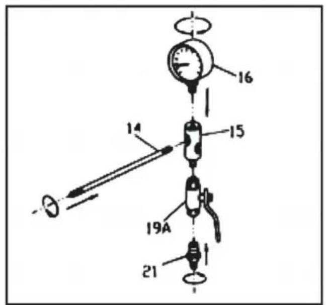
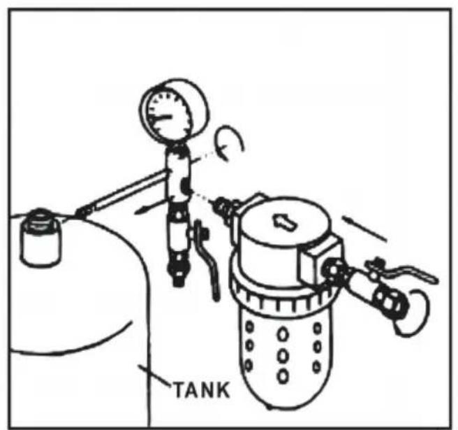
- Refer to the drawing for step 1, assembling the intake manifold. First, attach pressure gauge (16), to the top of the intake manifold, turning the gauge so that can be seen across the top of the tank. Next, attach the throttling valve (19A) to bottom of the manifold. Attach the nipple connector (21), to the throttling valve. Attach the joint pipe (14), to the manifold.
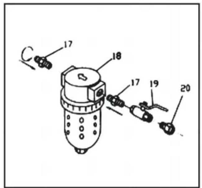
- Refer to the drawing for step 2, to assemble the water trap filter(18).
nipple connector(17) is screwed into each side of the filter. On one side, attach the air supply valve(19), to the nipple connector(17), and then attach the male/female connector (20), to the other side of the air supply valve. When you're ready to operate the abrasive blaster, the air hose from the compressor will fasten to the male/female connector (20).
- Place the tank (01) on a table with the four clips up. Refer to the drawing for Screw the water trap filter (18) and its parts into the hole at the side of the inta manifold. Then screw the open end of the joint pipe (14) with intake manifold (15) and pressure gauge (16) attached into the threaded hole on the side of the filler pipe on Top of the tank.Again,be sure that the manifold and gauge are vertical.
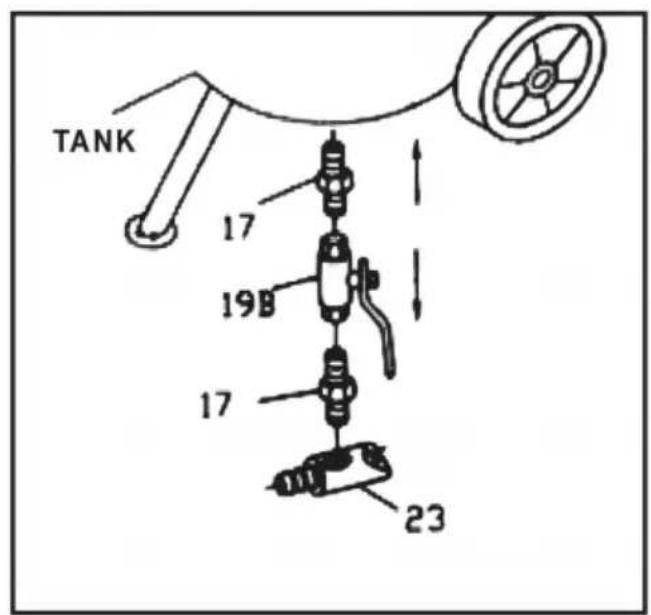
- Refer to the drawing for step 4, assembly of the abrasive outlet valve into the hole at the bottom of the tank; Attach four parts, in order: Nipple connector(17); abrasive metering valve (19B); nipple Connector(17) and the abrasive outlet pipe (23).
step 1
step 2
step 3
step 4
- Refer to the drawing for step 5, assembly of the nozzle DEADMAN valve (34) this assembly process, you'll select one of the four nozzles (28). This is not a permanent selection, as you may change nozzles according to the job being done. Screw the adapter (26), into the nozzle DEADMAN valve (34). Screw the gasket (27) into the nipple connector, then add a nozzle(28) and the nozzle cap-nut (29).
- Refer to the drawing for step 6, for connecting the abrasive metering valve assembly (step 4) and the assembly (step 5). Slide the two hose clamps (24), one of each end of the abrasive hose (25), press one end of the hose, over the nipple or the abrasive outlet pipe (23) and the other end over the adapter (26). Both hose ends should be firmly seated on the nipples. Slide the hose clamps along the hose to each nipple and tighten the clamps very firmly.
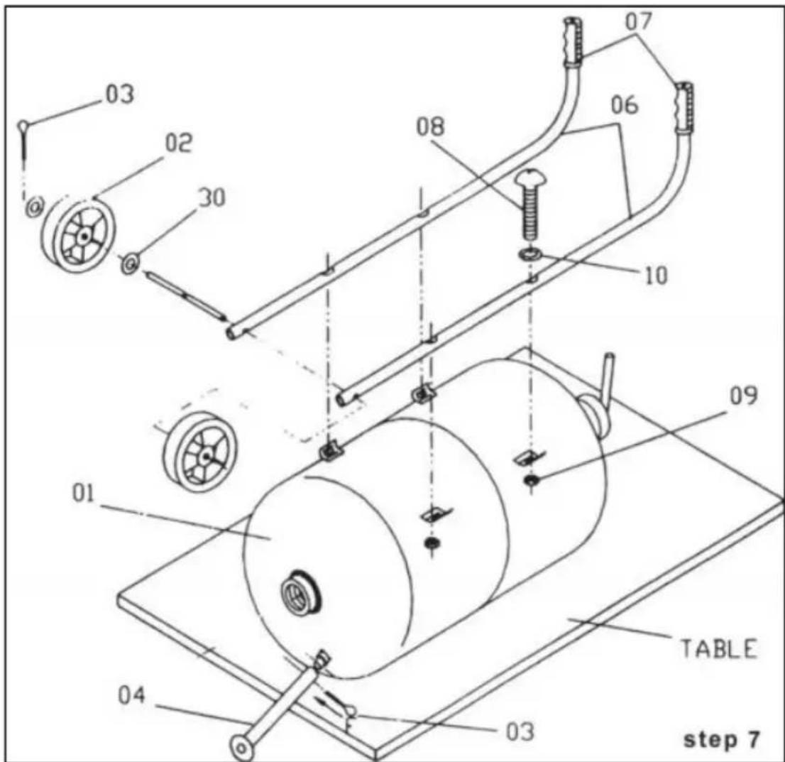
- Fasten the two handlebars (06) to the tank using four pan screws(08) and four washers(10) and four hex nuts (09). Note: keep the handle curve ends upward.
- Locate the axle (05), and slide it through the holes in the sides of the handle (06). Place one wheel (02) at each end of the axle and fasten then into place v cotter pins (03) and washer (30).
- Insert the fixed foot (04) onto the fitting on the bottom of the tank near the e Use your last cotter pin (03) to hold the foot to the tank.
- Before beginning operations, go back over each connection, double checking to ensure that all are tight and properly seated.
WARNING!
Disconnecting hose while Unit is under pressure could cause serious injury or death. Use safety lock pins and safety cables in all coupling connections to help prevent hose couplings from accidental disconnection.
If twist-on type air hose couplings are used, they must be secured by safety lock pins or wires to prevent accidental disconnection while under pressure. Hose disconnection while under pressure could cause serious injury.
PRESSURE BLASTER SAFETY PROCEDURES
CAUTION: READ THESE SAFETY PROCEDURES IN THEIR ENTIRETY-PARTS OF THE OPERATING INSTRUCTIONS ARE WITHIN THESE WARNINGS.
These procedures are not intended to be exhaustive due to the many variables in the abrasive blasting field. Therefore, we INSIST that the hands, ears, mouth,
nose and eyes be covered with appropriate safety protection at all times.
- Do not place fingers, any body parts or any components in the filler plug sea area when the blast machine is being pressurized. Failure to keep body parts from the filler plug area will result in serious injury.
- Do not exceed maximum working pressure of 125 PSI. Failure to keep maximum working pressure below 125 PSI can cause the blast machine to burst, causing death or serious injury.
- Everyone in the blast area including the equipment operator should correctly use and maintain a NIOSH-approved air-supplied respirator, even after blasting has ceased. Harmful dust can remain suspended in the air for long periods of time after blasting has ceased causing injury or death.
- Before using the pressure blaster: Put on safety glasses, gloves, and NIOSH-approved. respirator. Always wear these protective items when operating and while servicing your abrasive blaster. While a protective hood is provided to help protect you from flying part as you use the machine, the hood does not provide protection from air borne particles. A well maintained air supplied blasting respirator must be used by anyone blasting.
- Use thick gloves with to protect your hands.
- Use backboards to prevent over spray from hitting someone or something else because the dust will travel a long distance. Blast in a large open area to minimise abrasive accumulation in surrounding areas.
- Do not pull media tank around by the abrasive hose or let tank fall over as a fitting may break rendering the machine unsafe. Media and air under 125 PSI has a very high destructive force. Never leave a pressurized machine unattended. If an emergency occurs, such as a burst blast hose, shutdown the machine immediately.
- Drain air out of tank through the inlet valve and disconnect power before maintenance cleaning of any kind. When removing nozzle, caution must be exercised as air pressure may still be in the hose if the nozzle is plugged.
- For safe operation, perform recommended preventive maintenance on blaster tank, remote unit and accessories. Replace all worn parts before they fail. Immediate replacement of worn components is required. Failure to replace worn
components could result in exposing the operator or bystanders to high speed media and compressed air, causing serious injury.
- Do not use corrosive materials of any type in unit. Use only clean, dry medi
-
Do not splice abrasive hose. The splice will wear out quickly and may violent spray media over the surrounding area. A worn blast hose could suddenly fail by bursting, Couplings and nozzle holders may not adequately grip worn hose, causing them to blow off under pressure. Compressed air and abrasive escaping from a burst hose, or disconnected coupling or nozzle holder, could cause severe injury.
-
Welding, grinding, or drilling on the blast machine could weaken the vessel. Compressed air pressure could cause a weakened blast machine to rupture, resulting in death or serious injury. Welding, grinding, or drilling on the blast machine vessel, without a National Board R stamp voids the ASME and National board certification if applicable.
-
Always place the machine so that the outlet is pointed away from any object or persons. Stand clear of the path of exiting abrasive. It may come out at high velocity. Impact from exiting abrasive could cause severe injury.
-
Do not use electrical adaptors that eliminate the ground prong on 115 volt plugs. Failure to properly ground the machine can cause injury from electric shock and equipment damage. To help reduce the possibility of static electricity and its related hazards, always ground the Blast machine.
-
Do not use this equipment in any area that might be considered hazardous (where flammable gases or liquids are present. Failure to do so may cause an explosion resulting in serious injury.
-
Static electricity can be created by the use of this equipment. Do not Use with fifty feet of any explosive, potentially explosive Substances, or their vapors as an explosion can occur.
-
Do not overfill tank with media. Do not fill to within 6 inches from top of the
-
BEFORE OPENING THE TANK, release the air pressure on the abrasive tan To do this, turn off the air supply valve (19), and push down to open the DEAD valve(1), to release pressure in the line. Ensure that the tank pressure gauge reads zero, then open the tank.
-
MAINTAIN CORRECT AIR PRESSURE, maximum of 110PSI is recommended, pressure must not exceed 125PSI. If pressure exceeds 125PSI, stop all work immediately, and disconnect the air compressor to reduce the excess pressure. Do not investigate the blaster's pressure problem until the pressure gauge, reads zero.
OPERATING INSTRUCTIONS
OPERATINGTECHNIQUE:
- Connect air hose to air inlet valve. Manufacturer recommends using minimum incoming air hose of 1/2" I.D. Using an air hose smaller than 1/2" I.D. will restrict air volume and result in poor unit operation. Prior to injection of air, be certain air inlet valve and nozzle valve are in the OFF position. With Deadman Valve closed and filler plug tight, open air inlet valve allowing air to pressurize. Operating range of unit is 40 to 110 PSI Note: For proper nozzle selection, refer to nozzle select chart on page 11. After proper nozzle selection insert nozzle into retainer base. So again stwasher and slide retainer nut over nozzle and tighten by hand.
- The Pressure Blaster is equipped with a unique semi-automatic pull-up closure design. Manufacturer recommends a fine grade abrasive with granular size similar to that of table salt. This assures proper flow and reduces the possibility of nozz obstruction. When ready to pressurize container, pull up closure and turn on incoming air. The internal air pressure will seal the closure.
- With the blaster pressurized and abrasive flow regulator valve at base of unit closed, open ball valve allowing air to flow through by-pass hose to base of the Then holding the abrasive hose by nozzle retainer housing with nozzle directed away from unit and operator, quickly squeeze the Deadman Valve fully open and adjust the regulator valve at base of tank to bleed the abrasive into air flow. Slow open regulator valve until abrasive material is slightly visible. Once the regulator flow valve is adjusted to the desired setting, further adjustment should only be required when changing grade of abrasive material or when a nozzle with a different I.D. is used. Opening regulator valve too far will result in a clogged hose nozzle.
For best performance, the Deadman Valve should be opened and closed quickly.
WARNING!
Disconnecting hose while Unit is under pressure could cause serious injury or death. Use safety lock pins and safety cables in all coupling connections to help prevent hose couplings from accidental disconnection.
If twist-on type air hose couplings are used, they must be secured by safety lock pins or wires to prevent accidental disconnection while under pressure. Hose disconnection while under pressure could cause serious injury.
AIR ABRASIVE SUPPLY REQUIREMENTS
Abrasive blasting requires a large volume of air at high pressure. The efficiency of your abrasive blaster can be adversely affected by the use of too small an air supply hose, insufficient air pressure or an overly large nozzle.
| Hose ID | Hose Length | Nozzle ID | CFM (110 PSI) | Abrasive Use Per Hour |
| 3/8” | 50ft | 3/32” | 6 | 60 Lbs |
| 3/8” | 25ft | 7/64” | 12 | 100 Lbs |
| 1/2” | 50ft | 1/8” | 15 | 150 Lbs |
| 1/2” | 25ft | 9/64” | 20 | 200 Lbs |
We recommend that air pressure in the range of 60-110 PSI will provide best Results.
LOADING ABRASIVES INTO THE TANK
- Check your abrasive to be sure it's dry, and won't clog the metering valve (19 abrasive outlet pipe(23), hose(25), or other components.
- Put on the protective clothing, full hood and MSHA/NICOSH approved Respirator.
- Turn the air supply valve(19) to the off (horizontal)position.
- Push down to open the nozzle DEADMAN valve(34).
- Watch the pressure gauge(16) and make sure it reads zero pressure.
- Remove the filler cap(13) from the top of the tank. 6.
- Insert the funnel (31), and pour the abrasive into the funnel. Be sure to get
enough into the tank to do the job at hand. But if this is a big job, fill the tank 3/4 full, and reload as needed to finish the work.
TIPS: if the humidity is 90/100%, the water trap (18) won't be able to trap all of moisture in a 3/4 tank. Better to reduce the amount of abrasive, load more frequently, and empty the water trap more open. This will reduce the possibility of clogging the bottom of the tank or the line.
- with the correct amount of abrasive in the tank, close the filler cap (13).
- Close the nozzle shut-off valve(198), and open the air supply valve(19).
- Listen for air leaks at the filler cap as you begin to pressurize the tank from compressor.Fix any leaks before operating.
AIR COMPRESSOR RECOMMENDATION
To permit efficient operation of your air compressor, follow these guidelines: Use smaller size nozzle to control the demand of air.
- Do not blast continuously. Stop blasting operation periodically to allow the compressor to cool.
- No compressor is designed to constantly run at full RPM. Use 70% of the rat output. Use a minimum 1/2" air hose or metal piping from your air compressor to the blaster. If your
- compressor is creating an excessive amount of moisture, we recommend using a water trap or a moisture separator. Open the bleeder valve until water slowly flows out continuously.
- The air compressor should be drained at the bottom of the supply tank through drain valve and should be blown down daily. It is not unusual to drain three or 10 gallons of water from the supply tank on a high humidity day. An additional supply tank will help.
- Keep dust and media created by blasting away from the air compressor unit. Observe maximum air pressure requirements for the blaster and either set your compressor to run within these limits or use a pressure regulator valve to reduce the air pressure to the appropriate range.
ABRASIVE (MEDIA) USAGE
- If moisture is in the media it will eventually damage the blaster tank or plug its system. Keep the media and compressor air dry to avoid this problem.
- If media is moist, screen it and dry it before using.
- Do not leave media in the tank after blasting because it can absorb moisture and impair blasting performance.
- Store media in a dry place; keep media off the ground or concrete floors. Put on a wooden skid.
- If the humidity is excessively high, it may not be advisable to blast at that tin
- Consider using different grades or different types of media to prevent nozzle clogging due to high moisture content.
- Do not use sand.
Warning!
Do not fill the pressure vessel to within six (6) inches of the top of the vessel. hose is accidentally disconnected during use media spray may occur.
See respiratory related WARNINGS at the beginning of the manua
Black Beauty
Black Beauty is used when paint and rust has to be removed from steel, such as Car bodies, tanks or heavy machinery. Black Beauty is superior to silica because only has 0.1% free silica, is faster cutting, can be re-used, is moisture free, and will not pack or absorb moisture.
Steel Grit
Steel grit is extremely fast cutting on rusty metal and hard to remove paint. Steel Grit is popular because it leaves a very smooth finish. It is also comparable in Pr to most other specialty abrasives. Steel Grit is recommended in reclaim Systems or cabinets.
Glass Bead
Glass Bead is used in creating a satin or matte finish. Glass Bead is recommended in reclaim systems or cabinets.
Aluminum Oxide
Aluminum Oxide is a high quality abrasive that is sharper than sand (not recommended) and cuts twice as fast as sand. It leaves a smooth textured finish with no pits. Aluminum Oxide is rougher than glass bead and can be used over and over again. It is one of the most economical abrasives you can use in any reclaim systems or cabinets.
Plastic Grit
Primarily used to strip aluminum and fiberglass.Great for stripping paint.Light oxidation and surface rust.Recommended for use is blast cabinets because it creates very little dust.Works quickly,last a long time and increases visibility within the cabinet.
TROUBLE SHOOTING TIPS
| PROBLEM/CAUSE | POSSIBLE SOLUTION |
| Surging of blast flow: | |
| Air pressure too low | See "Lack of Air Pressure" |
| Too much media | Adjust media valve |
| Excessive media consumption: | |
| Media valve open too far | Close slightly |
| Air pressure too low | Check pressure gauge |
| Clogging and plugging of blast flow: | |
| Debris in media | Purge and screen |
| Media size too large | Use smaller grit size |
| Nozzle plugs | Use larger nozzle |
| Nozzle plugs | Adjust media valve |
| Wet media | Dry media,drain water from air |
| Moisture in abrasive media: | |
| Wet media | Change or use dry media |
| Water in air | Drain water from airlines |
| Water in tank | Empty,dry out and refill |
| Humid weather: | |
| Moderate humidity | Keep media as dry as possible |
| Moderate humidity | Use drier or moisture separator |
| High humidity | Avoid that period of use if possibl |
| Overtaxed compressor: | |
| Compressor too small | Restrict time used |
| Nozzle size too large | Use smaller size |
| Too many leaks in plumbing | Seal and tighten plumbing |
| Holes in abrasive hose | Replace hose |
| Air filter on compressor plugged | Clean |
| Lack of air pressure: | |
| Compressor too small | Use smaller nozzle |
| Supply valves not on full position | Open valves |
| Nozzle size too large | Use smaller size |
| Leaks in plumbing | Seal and tighten plumbing |
| Holes in abrasive hose | Replace hose |
| Air filter on compressor plugged | Clean filter |
| Urethane gasket worn or dirty | Clean or replace gasket |
| Lack of abrasive flow: | |
| Blaster tank empty | Fill tank |
| Moisture in media | Dry media |
| Not enough air pressure | Check system |
| Abrasive hose kinked | Straighten hose |
| Debris in media | Clean or screen media |
MAINTENANCE
WARNING!
Failure to observe the following before performing any maintenance could cause serious injury or death from the sudden release of compressed air:
- Depressurize the blast machine.
- Disconnect power supply.
- Lockout and tag out the compressed air supply.
- Bleed the air supply line to the blast gun.
Immediate replacement of worn components is required. Failure to replace worn components could expose the operator or bystanders to high speed media and compressed air could cause death or serious injury.
Leaks around couplings and nozzle holders indicate worn or loose fitting parts. Nozzle holders and couplings that do not fit tightly on hose and nozzles that do fit tightly in nozzle holders could disconnect while under pressure. Impact from nozzles, couplings, hoses, or abrasive, and parts disconnected while under pressure could cause severe injury. To ensure a long and efficient operational life of the Deadman Handle, it is highly recommended that the following procedures be followed:
- Periodically(after 5-6 months of moderate use or after 10-15 hours of heavy industrial use) replace all hose adaptors that are for abrasive flow use only.
- Replace rubber sealing block on after 7-10 hours of use to maintain proper shut-off.
- Check abrasive hose when it begins tos often or leaks media or air around th hose or handle area.
- Replace the nozzle when it wears to the next larger size.
- Check the urethane gasket in the pull-up closure when the air leaks excessive from the opening (make sure the gasket is free from media).
- You should make every effort to protect your air compressor from any damage may receive from your abrasive blasting work. Your best option is to keep the compressor up wind from the abrasive blasting, and the greater the distance between them, the better. Other than that, you should continue standard maintenance procedures for the compressor.
- Some parts of the abrasive blaster will wear much more rapidly than others, t parts needing close attention carry the air/abrasive mixture, starting with the abrasive hose (25) and going through the metal fillings, the DEADMAN valve (34)
and the ceramic nozzles (28).
- If air leaks develop in any of these parts, you should stop all work, and find 3. what needs to be repaired or replaced. When it's new, the abrasive hose (25) has 2 cord piles and the walls are 1/4" thick. As the interior diameter is abraded this wall becomes thinner and thinner. One way to inspect the hose and other pa affected by the blasting is to put on your protective clothing. Then pressurize the system and close the nozzle shut off the valve (19). Listen for air leaks, fix any leaks before operating. You can also spot places in the hose where the wall is getting very thin. These show up as blisters in the hose; if you find such a blister get a new hose immediately. If that blister breaks, the abrasive will come out of side of the hose.
Address: Baoshanqu Shuangchenglu 803long 11hao 1602A-1609shi Shanghai
Imported to AUS: SIHAO PTY LTD, 1 ROKEVA STREETEASTWOOD NSW 212 Australia
Imported to USA: Sanven Technology Ltd., Suite 250, 9166 Anaheim Place, Rancho Cucamonga, CA 91730
| UK | REP |
Pooledas Group Ltd
Unit 5 Albert Edward House, The Pavilions
Preston, United Kingdom
| EC | REP |
SHUNSHUN GmbH
Römeräcker 9 Z2021, 76351
Technical Support and E-Warranty Certificate www. vevor. com/support
VEVOR®
TOUGH TOOLS, HALF PRICE
natural_image
Red fire extinguisher with attached hose and valve (no visible text or symbols)BESOIN D'AIDE? CONTACTEZ-NOUS!
PARAMÈTRES DU PRODUIT
| LISTE DES PIECES | |||||
| DESCRIPTION DE LA PIÈCE QTÉ | DESCRIPTION DE LA PIÈCE | QTÉ | |||
| 01 | RÉSERVOIR | 1 | 18 | PIÈGE À EAU FILTRE | 1 |
| ROUES | 2 | 19 | AIR EN LAITON FOURNIR02 SOUPAPE,3/8" | 1 | |
| 03 | GOUPILLES FENDUES | 5 | 19A | LAITON LÉGÈREMENT SOUPAPE,3/8" | 1 |
| 04 | PIED | 1 | 19B | LAITON ABRASIF MESURE SOUPAPE,3/8" | 2 |
| 05 | ESSIEU | 1 | 20 | HOMME FEMME CONNECTEUR | 1 |
| 06 | GUIDONS | 2 | 21 | MAMELON CONNECTEUR | 1 |
| 07 | 2 | 22 | TUYAU D'AIRPOIGNÉES | 1 | |
| 08 | VIS PNA | 4 | 23 | ABRASIF TUYAU DE SORTIE | 1 |
| 09 | ÉCROU HEXAGONAL | 4 | 24 | SERRER | ^2 |
| dix | MACHINE À LAVER | 4 | 25 | TUYAU ABRASIF | 1 |
| 11 | SOUPAPE DE SÉCURITÉ | 1 | 26 | MAMELON | 1 |
| 12 | JOINT TORIQUE | 1 | 27 | CAOUTCHOUC BUSE JOINT | 1 |
| 13 | FILLER CAP | 1 | 28 | CÉRAMIQUE BUSE | 4 |
| 14 | TUYAU IONITE | 1 | 29 | ECROU AVANT | 1 |
| 15 | ADMISSION COLLECTEUR | 1 | 30 | MACHINE À LAVER | 4 |
| 16 | PRESSION JAUGE | 1 | 31 | HOMME MORT SOUPAPE ADAPTATEUR | 1 |
| 17 | MAMELON CONNECTEUR | 4 | |||
BUSES: A=9/64"D=3/32" B=1/8" C=7/64"
NOTES D'INSTALLATION
natural_image
Red industrial pressure vessel with black hose and attached tubing (no visible text or symbols)BRAUCHEN SIE HILFE? KONTAKTIERE UNS!
| LISTE DER EINZELTEILE | |||||
| TEILBESCHREIBUNG MENGE TEILBESCHREIBUNG | MENGE | ||||
| 01 | PANZER | 1 | 18 | WASSERFALLE FILTER | 1 |
| 02 LIEFERN RÄDER | 2 | 19 | MESSING LUFT VENTIL, 3/8 Zoll | 1 | |
| 03 | Splinte | 5 | 19A | MESSING DROSSELN VENTIL, 3/8 Zoll | 1 |
| 04 | FUSS | 1 | 19B | MESSING SCHLEIFMITTEL DOSIERUNG VENTIL,3/8" | 2 |
| 05 | ACHSE | 1 | 20 | MÄNNLICH WEIBLICH VERBINDER | 1 |
| 06 | LENKER | 2 | 21 | NIPPEL VERBINDER | 1 |
| 07 | GRIFFGRIFFE LUFTSCHLAUC2 | 22 | 1 | ||
| 08 | PNA-SCHRAUBE | 4 | 23 | SCHLEIFMITTEL AUSLASSROHR | 1 |
| 09 | SECHSKANTMUTTER KLEMME 4 | 24 | ∞ | ||
| 10 | WASCHMASCHINE | 4 | 25 SCHLEIFSCHLAUCH | 1 | |
| 11 | SICHERHEITSVENTIL | 1 | 26 | NIPPEL | 1 |
| 12 | O-RING | 1 | 27 | GUMMI DÜSE DICHTUNG | 1 |
| 13 | EINFÜLLVERSCHLUSS | 1 | 28 | KERAMIK DÜSE | 4 |
| 14 | IONIT-ROHR | 1 | 29 | VORDERE MUTTER | 1 |
| 15 | AUFNAHME VERTEILER | 1 | 30 | WASCHMASCHINE | 4 |
| 16 | DRUCK MESSGERÄT | 1 | 31 | TOTER MANN VENTIL ADAPTER | 1 |
| 17 | NIPPEL VERBINDER | 4 | |||
DÜSEN: A=9/64 Zoll D=3/32 Zoll B=1/8 Zoll C=7/64 Zoll
INSTALLATIONSHINWEISE
natural_image
Red industrial pressure vessel with black hose and attached tubing (no visible text or symbols)HO BISOGNO DI AIUTO? CONTATTACI!
| ELENCO DELLE PARTI | |||||
| DESCRIZIONE DELLA PARTE QUANTITÀ | DESCRIZIONE DELLA PARTE | QUANTITÀ | |||
| 01 | CISTERNA | 1 | 18 | TRAPPOLA D'ACQUAFILTRO | 1 |
| 02 | RUOTE | 2 | 19 | ARIA IN OTTONEFORNITURAVALVOLA,3/8" | 1 |
| 03 | COPPIE | 5 | 19A | OTTONEGOTTURAVALVOLA,3/8" | 1 |
| 04 | PIEDE | 1 | 19B | OTTONEABRASIVODOSAGGIOVALVOLA,3/8" | 2 |
| 05 | ASSE | 1 | 20 | MASCHIO FEMMINACONNETTORE | 1 |
| 06 | MANUBRI | 2 | 21 | CAPEZZOLOCONNETTORE | 1 |
| 07 | MANIGLIE | 2 | 22 | TUBO DELL'ARIA | 1 |
| 08 | VITE PNA | 4 | 23 | ABRASIVOTUBO DI SCARICO | 1 |
| 09 | DADO ESAGONALE | 4 | 24 | MORSETTO | ∞ |
| 10 | RONDELLA | 4 | 25 TUBO ABRASIVO | 1 | |
| 11 | VALVOLA DI SICUREZZA | 1 | 26 | CAPEZZOLO | 1 |
| 12 | O-RING | 1 | 27 | GOMMAUGELLOGUARNIZIONE | 1 |
| 13 | TAPPO DI RIEMPIMENTO | 1 | 28 | CERAMICA UGELLO | 4 |
| 14 | TUBO IONITE | 1 | 29 | DADO ANTERIORE | 1 |
| 15 | ASPIRAZIONE COLLETTORE | 1 | 30 | RONDELLA | 4 |
| 16 | PRESSIONE MISURA | 1 | 31 | UOMO MORTO VALVOLA ADATTATORE | 1 |
| 17 | CAPEZZOLO CONNETTORE | 4 | |||
UGELLI: A=9/64"D=3/32" B=1/8" C=7/64"
Importato in AUS: SIHAO PTY LTD, 1 ROKEVA STREETEASTWOOD NSW 2122
Australia
Rancho Cucamonga, CA 91730
| REP. DEL | REGNO UNITO |
Gruppo Pooledas Ltd
natural_image
Red industrial pressure vessel with black hose and attached tubing (no visible text or symbols)BOQUILLAS: A=9/64"D=3/32" B=1/8" C=7/64"
natural_image
Red industrial pressure vessel with black hose and attached tubing (no visible text or symbols)POTRZEBUJE POMOCY? SKONTAKTUJ SIĘ Z NAMI!
| LISTA CZĘŚCI | |||||
| OPIS CZĘŚCI ILOŚĆ OPIS CZĘŚCI | ILOŚĆ | ||||
| 01 | CZOŁG | 1 | 18 | PUŁAPKA WODNA FILTR | 1 |
| KOŁA | 2 | 19 | MOSIĘŻNE POWIETRZE DOSTARCZAĆOZ ZAWÓR,3/8" | 1 | |
| 03 | ZACZEPKI | 5 | 19A | MOSIĄDZ DŁAWIENIE ZAWÓR,3/8" | 1 |
| 04 | STOPA | 1 | 19B | MOSIĄDZ ŚCIERNY DOZOWANIE ZAWÓR,3/8" | 2 |
| 05 | OŚ | 1 | 20 | MĘŻCZYZNA-Kobieta ZŁĄCZE | 1 |
| 06 | KIEROWNICE | 2 | 21 | SUTEK ZŁĄCZE | 1 |
| 07 | UCHWYTY UCHWYTU | 2 | 22 | Wąż POWIETRZA | 1 |
| 08 | ŚRUBA PNA | 4 | 23 | ŚCIERNY RURA WYLOTOWA | 1 |
| 09 | NAKRETKA SZEŚCIOKATNA | 4 | 24 | ZACISK | 2 |
| 10 | PRALKA | 4 | 25 Wąż ŚCIERNY | 1 | |
| 11 | ZAWÓR BEZPIECZEŃSTWA | 1 | 26 | SUTEK | 1 |
| 12 | O-RING | 1 | 27 | GUMA DYSZA USZCZELKA | 1 |
| 13 | KOREK WLEWU | 1 | 28 | CERAMICZNYDYSZA | 4 |
| 14 | RURA JONITOWA | 1 | 29 | NAKRĘTKA PRZEDNIA | 1 |
| 15 | WLOTKOLEKTOR | 1 | 30 | PRALKA | 4 |
| 16 | CIŚNIENIEMIERNIK | 1 | 31 | MARTWY CZŁOWIEKZAWÓRADAPTER | 1 |
| 17 | SUTEKZŁĄCZE | 4 | |||
DYSZE: A=9/64"D=3/32"B=1/8"C=7/64"
UWAGI INSTALACYJNE
Import do AUS: SIHAO PTY LTD, 1 ROKEVA STREETEASTWOOD NSW 2122
Australia
Import do USA: Sanven Technology Ltd., Suite 250, 9166 Anaheim Place, Rancho Cucamonga, CA 91730
natural_image
Red industrial fire extinguisher with attached hose and valve (no visible text or symbols)HULP NODIG? NEEM CONTACT MET ONS OP!
GEZONDHEIDSRISICO WAARSCHUWING
WAARSCHUWING!
| ONDERDELEN LIJST | |||||
| ONDERDEELBESCHRIJVING AANTAL ONDERDEELBESCHRIJVING | AANTAL | ||||
| 01 | TANK | 1 | 18 | WATER VAL FILTER | 1 |
| WIELEN | 2 | 19 | MESSING LUCHT LEVERING02 KLEP,3/8" | 1 | |
| 03 | SPIEPENNEN | 5 | 19A | MESSING DRUKKEREN KLEP,3/8" | 1 |
| 04 | VOET | 1 | 19B | MESSING SCHUREND METERING KLEP,3/8" | 2 |
| 05 | AS | 1 | 20 | MAN VROUW CONNECTOR | 1 |
| 06 | HANDBEUKEN | 2 | 21 | TEPEL CONNECTOR | 1 |
| 07 | HANDVATTEN | 2 | 22 | LUCHTSLANG | 1 |
| 08 | PNA-SCHROEF | 4 | 23 | SCHUREND AFVOERPIJP | 1 |
| 09 | ZESKANTMOER | 4 | 24 | KLEM | ∞ |
| 10 | WASMACHINE | 4 | 25 SCHURENDE SLANG | 1 | |
| 11 | VEILIGHEIDSKLEP | 1 | 26 | TEPEL | 1 |
| 12 | O-RING | 1 | 27 | RUBBER MONDSTUK PAKKING | 1 |
| 13 | VULDOP | 1 | 28 | KERAMIEKMONDSTUK | 4 |
| 14 | IONIET PIJP | 1 | 29 | VOORMOER | 1 |
| 15 | INNAMEVERDEELSTUK | 1 | 30 | WASMACHINE | 4 |
| 16 | DRUKGRAADMETER | 1 | 31 | DODE MANVENTIELADAPTER | 1 |
| 17 | TEPELCONNECTOR | 4 | |||
NOZZLES: A=9/64"D=3/32" B=1/8" C=7/64"
GEBRUIKSHANDLEIDING
natural_image
Red industrial fire extinguisher with attached black hose and valve (no visible text or symbols)BEHÖVS HJÄLP? KONTAKTA OSS!
| DELLISTA | |||||
| DELBESKRIVNING ANTAL DELBESKRIVNING | ANTAL | ||||
| 01 | TANK | 1 | 18 | VATTENFÄLLA FILTRERA | 1 |
| HJUL | 2 | 19 | MÄSSING LUFT TILLFÖRSEL02 VENTIL, 3/8" | 1 | |
| 03 | SPINNINGAR | 5 | 19A | MÄSSING TROTTANDE VENTIL, 3/8" | 1 |
| 04 | FOT | 1 | 19B | MÄSSING SKROVLIG MÄTNING VENTIL, 3/8" | 2 |
| 05 | AXEL | 1 | 20 | MAN KVINNA KONTAKT | 1 |
| 06 | HANDTAG | 2 | 21 | NIPPEL KONTAKT | 1 |
| 07 | HANDTAG | 2 | 22 | LUFTSLANG | 1 |
| 08 | PNA-SKRAV | 4 | 23 | SKROVLIG UTGÅNGSRÖR | 1 |
| 09 | SEXKANTSMUTTER | 4 | 24 | KLÄMMA | ∞ |
| 10 | BRUCKOR | 4 | 25 SLIPSLANG | 1 | |
| 11 | SÄKERHETSVENTIL | 1 | 26 | NIPPEL | 1 |
| 12 | O-RING | 1 | 27 | SUDD MUNSTYCKE PACKNING | 1 |
| 13 | PÄFYLLNINGSLOCK | 1 | 28 | KERAMISKMUNSTYCKE | 4 |
| 14 | IONITE RÖR | 1 | 29 | FRAMMUTTER | 1 |
| 15 | INTAGGRENRÖR | 1 | 30 | BRUCKOR | 4 |
| 16 | TRYCKMÄTARE | 1 | 31 | DÖD MANVENTILADAPTER | 1 |
| 17 | NIPPELKONTAKT | 4 | |||
MUNGAR: A=9/64"D=3/32" B=1/8" C=7/64"
INSTALLATIONSANMÄRKNINGAR
Enhet 5 Albert Edward House, The Pavilions