GX5088 - Polisher Vevor - Free user manual and instructions
Find the device manual for free GX5088 Vevor in PDF.

| Product Type | Polisher / Burnisher |
| Brand | Vevor |
| Model | GX5088 |
| Supply Voltage | 220 V (50 Hz) / 110 V (60 Hz) |
| Rated Power | 1200 W |
| No-load Speed | 730 - 3200 rpm (NA) / 950 - 3200 rpm (EU) |
| Polishing Wheel | 120 × 100 mm |
| Speed Adjustment | 6 speeds (1-6) |
| Intended Use | Commercial: burnishing, polishing, brushing, deburring, rust removal |
| Compatible Materials | Steel, stainless steel, non-ferrous metals, wood, plastics |
| Auxiliary Handle | Yes, removable |
| Protective Guard | Yes, adjustable towards operator |
| Switch | With lock for continuous operation |
| Double Insulation | Yes |
| Carbon Brushes | User-replaceable (pair) |
| Spare Parts Available | Switch, power cord, brushes, wheel |
| Maintenance | Regular cleaning of ventilation slots and dust filter |
| Warranty | Factory warranty according to country of use regulations |
| Standards | European Directive 2012/19/EU (WEEE) |
| Manufacturer | Shanghaimuxinmuyeyouxiangongsi, Shanghai, China |
Frequently Asked Questions - GX5088 Vevor
User questions about GX5088 Vevor
0 question about this device. Answer the ones you know or ask your own.
Ask a new question about this device
Download the instructions for your Polisher in PDF format for free! Find your manual GX5088 - Vevor and take your electronic device back in hand. On this page are published all the documents necessary for the use of your device. GX5088 by Vevor.
USER MANUAL GX5088 Vevor
Technical Support and E-Warranty Certificate www.vevor.com/support
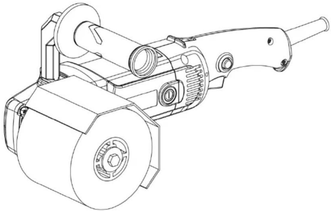
Burnishing Polishing Machine
MODEL:GX5088
We continue to be committed to provide you tools with competitive "Save Half", "Half Price" or any other similar expressions used by represents an estimate of savings you might benefit from buying cer with us compared to the major top brands and does not necessarily cover all categories of tools offered by us. You are kindly reminded carefully when you are placing an order with us if you are actually in comparison with the top major brands.
VEVOR®
TOUGH TOOLS, HALF PRICE
Burnishing
Polishing Machine
MODEL:GX5088
natural_image
Technical line drawing of a mechanical device with gears and shafts (no text or symbols)NEED HELP? CONTACT US!
Have product questions? Need technical support? Please feel fr contact us:
Technical Support and E-Warranty Certificate www.vevor.com/support
This is the original instruction, please read all manual instructions carefully before operating. VEVOR reserves a clear interpretation of user manual. The appearance of the product shall be subject to product you received. Please forgive us that we won't inform your use, there are any technology or software updates on our product.
Preface
First of all, let us express our heartfelt thanks to our customers who have purchased our equipment. This manual is for customer service to make better. Written with this equipment. Hope the company's products and services to bring you the canal courtesy.
Important reminder
For your own safety, before assembling and using such products, you must find read this manual to clarify the unique operation, application, and possible problems of this equipment.
This manual is consistent with the date of manufacture of your machine, you find information on the technical data of the machine acquired manual check updates of our machines at the after-service site or related website.
This burnishing machine is designed for:
- Commercial use in industries and trades.
- Surfaces processing such as, for example, burnishing, structuring, polishing, brushing, smoothing, removing rust or burrs from steel or stainless steel or non-metal materials.
-Choose proper wheel when treating wood surfaces.
Read this manual carefully before use
The general rules of safety
Warning! Read the instructions Without according to the following instructions I use or operation will lead to electric shock, fire or serious injury. On all terms following example warning "power tools" refers to the utility driver (cable) power tools or battery-powered electric tools (wireless).
Save these instructions
A) work place
1) keep work place clean and bright. Chaos and dark field can cause accident
2) don't in any flammable liquid, gas or powder under the environment of the operating power tools, electric tools sparks can ignite powder dust or gas.
3) let children and onlookers left manipulation of electric tools. The distraction help you to relax control
B) electrical safety
1) power tools must be matched with the socket, plug must not be modified way plug. Need grounding electric tools cannot use any conversion plug. With modification of plug and socket suitably will reduce the electric shock risk.
2) to avoid human contact with the ground, such as pipe, heat sink and ref. If you earthing body, will increase the risk of electric shock.
3) the electric tools must not be exposed in the rain or damp environment. into electric tools will increase the risk of electric shock.
4) shall not abuse their power lines. Wires must not be handling, pull the p tools or pull the plug. Keep electric tools away from heat, oil, sharp edges of moving parts. Damaged or coil of wire will increase the risk of electric shock
5) when using power tools in the outdoor, use external wire of outdoor use. Suitable for outdoor use lines will reduce the shock hazard.
C) the personal safety
1) be alert, when operating a power tool in operation and attention is in state. Not in fatigue, drugs, alcohol or treatment response under the operation of electric tools. During the operation of electric tool distractions can cause serious personal injury.
2) use the security device. Always wear goggles. Safety devices, such as the appropriate conditions of dust masks, antiskid safety shoes, safety helmet,, such as hearing protection device can reduce personal injury.
3) avoid sudden starting. Ensure that the switch in the off position when insert into the plug. Finger on the switch has been switched on or switch is switch when inserted into the plug may cause danger.
4) before the electric tools through, remove all keys or wrench adjustment. Let in electric tool wrench or key on the rotating parts can cause personal injury
5) hands don't stretch too long. Always watch your step and balance. So un consciousness can well control electric tools.
6) dress appropriately. Don't wear loose clothes or wear jewelry. Let your hair clothes and sleeves away from moving parts. Loose clothing, accessories, or hair may be involved in the moving parts.
7) if provided with chip removal device, dust collecting device connection was made using the device, ensure that their connection condition and used proper. Using this device can reduce the risk of debris caused.
D) power tools to use and the matters needing attention
1) don't abuse power tools, according to the application using the appropriate power tools. Choose the appropriate design rating power tools will make your more effective and safer.
2) if the switch is not connected or shut off the power, are not allowed to tool. Can't use the switch to control the electric tool is a dangerous and more repaired.
3) in any regulation, before changing accessories or store electric tools, must the plug from the power supply or battery box off power supply. The protect measures to reduce the risk of electric tools suddenly start.
4) will be idle power tools storage in children and scope, and don't let not with electric tools or do not understand these instructions to operate power to Power tools in the hands of untrained user is dangerous.
5) maintenance of electric tools. Check the installation of the moving part device, or stuck, parts damage and other conditions affecting electric tool. If there are damage, electric tools must be repaired before use. Many accidents caused by poor maintenance of electric tools.
6) keep cutting tools sharp and clean. Maintain good cutting tool with a shar cutting edge not easily jammed and easy to control.
7) according to the instruction for use, and intends to use the way of special electric tool requirements, operation conditions and operation to use power tools accessories box tool cutting head, etc. Electric tools will be used for those who not tally with the requirements of operation may cause dangerous situation.
E) maintenance
1) your power tools to the company for repair, maintenance must use the safety parts for replacement. Say so to ensure the maintenance of the safety of electric tools.
2) on a regular basis to clean up, maintenance and add lubricating oil (grea
3) user replaceable parts as follows: the brush, switch, the power cord.
Wire sanding, sanding, sanding and polishing or abrasive cutting operation of general safety warning:
A) the power tool is used for realizing the function of polishing machine tools with the electric tool provides all of the safety warning, instructions, diagrams rules. Don't understand all the below listed information will lead to click, fire serious injury.
B) is not recommended to use the electric tools such as grinding, sanding, brushing or cutting operation. Electric tools according to the specified function operate, not dangerous and cause personal injury may occur.
C) do not use the tool manufacturers recommendations and specially designed attachment. Otherwise the attachment may be put on your electric tool, and i guarantee safe operation.
D) the attachment must be at least equal to the rated speed of mark the n speed of electric tools. Attachment is greater than the rated speed of speed operation will burst and splash.
E) outside diameter and thickness of attachment must be in the range of ele tools rated capacity. Incorrect attachment size does not get adequate protection and control.
F) grinding wheel, flange, back cushion, or any other accessories shaft hole must be suitable for installation on electric tool spindle. With a shaft hole, an electric tools installation pieces not attachments will be instability, excessive vibration and may cause out of control.
G) do not use damaged accessories. Before each use to check the attachment such as grinding wheel debris and crack, the back cushion for cracks, tear, excessive wear, whether loose whether wire brush or wire fracture. If fell from electric tools and accessories, check whether there is damage or installation accessories, and without any damage after inspection and installation accessories let oneself and onlookers location away from the plane of the rotary attachment and the electric tool maximum no-load running for 1 min. Normally, in the experiment, burst damage of the accessories.
H) to wear protective equipment. According to the applicable condition, applica masks, safety goggles or safety glasses. When applicable, wear dust mask, hearing protector, gloves, and can work in little bits of the abrasive or artifact apron. Eye shield must stop flying debris produced various operations. Dust n or respirator must be able to filter operation generated particles. Long-term exposure to high intensity noise can cause hearing loss.
I) let the onlookers and the working area to keep a safe distance. Any people entering the work area must wear protective equipment. Work or fragments of broken accessories may fly out and lead to close operation area of the byst cutting attachment hit a charged conductor can make electric tools exposed r parts charged, and make the operator to get an electric shock.
In cutting attachments may cut the dark lines or its place of wire during operation only through the insulation grip surface to hold power tools. Met a charged conductor cutting attachments may make electric tool exposed gold
Parts are charged and make the operator shock hazard.
Note: if the polishing operation is the only operation, recommend the above warning can be omitted.
K) make the cord away from the rotary attachment. If improper control, cord cut off or winding, and makes your hands or arms may be involved in rotat the attachment.
L) until attachments completely stop moving down electric tools, spinning accessories may be captured surface and pull the power tools and make you control over tool
M) when carrying electric tool is not to start it, accidentally hit and rotate attachments may your clothes and make the accessories damage the body.
N) often clean electric tool vents, electric tools fan will inhale dust into the high metal powder deposition can lead to electrical hazards.
O) don't operating electric tools in the vicinity of flammable materials, grey M to fire the material.
Special safety code
The following items are the safety precautions for using the throwing mill, ple strictly observe them, or it may damage the tool or damage the body.
- Be sure to use the shields after the installation.
- The screws on the grinding wheel must be tightened before use.
- Before switching the grinding wheel, we must unplug the plug from the so so as not to accidentally connect the power switch of the tool and cause ac
- Use auxiliary handle and hold tools with both hands to achieve full control
- Be sure to secure the tool before starting it.
- Before grinding, the rotation direction of the grinding wheel should be checked with the direction of the arrow marked by the head of the gearbox.
- Do not use water or grinding fluid.
- Do not clamp the tool on a bench clamp or fixture.
- Goggles must be worn to prevent splashing and grinding particles into the
- After operation, do not drop the tool until it stops turning completely.
- Always ensure that the power cord does not make contact with the grind wheel.
-
If the tool accidentally falls or collides, check the grinding wheel and bock damage, rupture or deformation.
-
When using an extended power cord, use a double insulated power cord the same specification as this tool.
- When using this tool in wet, narrow workplaces, a short-circuit automatic electrical breaker (30mA) shall be used to protect the operator safety.
Operation Declaration
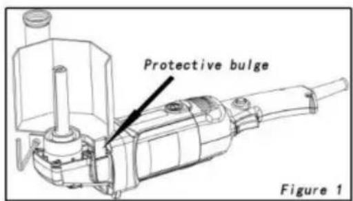
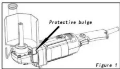
◆ Install and remove the shield
Installation: say that the protruding part of shield is against the head shell, the cover of the shield is toward the operator, tighter the fastening screws. (Figure 3)
Remove: loosen the fastening screws to re the shield
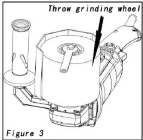
Remember: the cover of the shield must be toward the open to avoid splashing debris to the body.
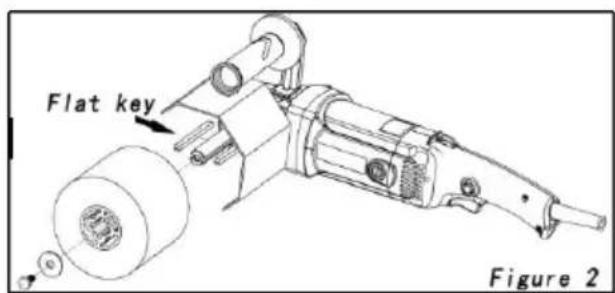
◆ Install and remove the throwing grinding wheel
Remember: Always remove the plug from the power supply before install and unplug the grinding wheel.
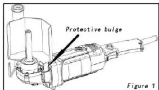
Install the grinding wheel: install the flat keys in the groove on both sides of spindle (Figure 2), then install the grinding wheel on the spindle, press the I button or grasp the grinding wheel (the power supply must be cut off), and the pressure plate screw (Figure 1).
Remove the grinding wheel: unscrew the pressure plate screw and remove the throwing wheel.
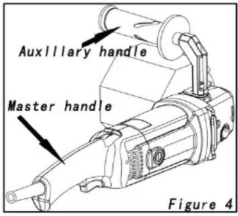
◆ Install the auxiliary handle:
Install the auxiliary handle on the head case add a flat pad to adjust if the position is n convenient to operate. After installing the aux handle, holding the handle in one hand and other hand can better control the tool (Figure
Switch
Note: Before the plug enters the power supply, check that the switch lock but ejected, the switch trigger action is fle and the lock button is released.
Press the switch and trigger tool to start Release the trigger tool to turn off and gradually stop running.
Press the switch trigger, then press the lock button, and then release the switch trigger.
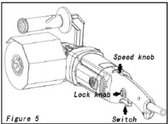
The tool is in continuous operation, press the switch trigger to release the lock button, turn the tool off and gradually stop running.
This tool has 1\~6 gear speed adjustment function, you can choose the approach speed grinding (Figure 5).
◆ Is Effective And Safe Grinding Method
- When grinding, start the tool and then contact the workpiece; after grinding leave the tool get away from the workpiece and close the tool.
- When the grinding wheel is not allowed to collide with the workpiece or the force is too large. Pressure should be applied gradually, to make the grinding wheel not suffer the impact force, so as to avoid the grinding wheel burst a accident.
- Generally, a soft grinding wheel is used for processing hard materials.
4.
Maintenance & Inspection
Remember: you must unplug the plug from the power supply before maintenance and check.
Often remove the dust, oil stains and other bad attachments on the tools. K tools clean and the knives sharp.
Always check that the connection part screws should not be loose.
Check the insulation layer of power cord should be free from damage.
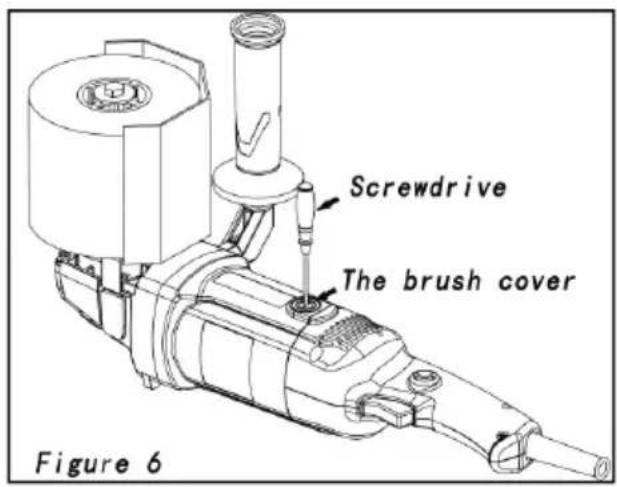
◆ Replacement Brush
When the spark is large or stops ru the brush shall be replaced.
Unscrew the brush cap with the star remove the worn brush, install the no brush, confirm that the brush slides in the hole, and then tighten the brush cap (Figure 6).
Be sure to replace both brushes asame time and use the original brush.
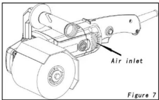
◆ Clean cleaning cleaning is cleaned cleaning for safe operation (Figure 7).
The accumulation of dust can prevent tool from working normally. Remove dust net, blow out the dust net, bru other parts can effectively extend the service life of the tool.
Quality Assurance
◆ All tools produced by Company have factory guarantee, and their repair of return period will meet the provisions of the country of use.
◆ Damage due to natural consumption, overload or wrong operation is not
included in the factory warranty scope.
◆ Must not remove tools and can only be repaired or replaced by sending back to the store.
Repair
When the user changes the switch, power cord and brush, Please use our original factory accessories.
◆ To ensure the safety and reliability of the tools, please send your tool to repair station for repair.
Specifications
| model | MOD: GX5088 SIN-GX-120×100 |
| source | Individual communication,220 V, 50 H z/110V 60HZ |
| Rated input power | 1200W |
| unloaded speed | NA: 730~3200r/minEU: 950~3200r/min |
| Throw grinding wheel | Φ120×100mm |
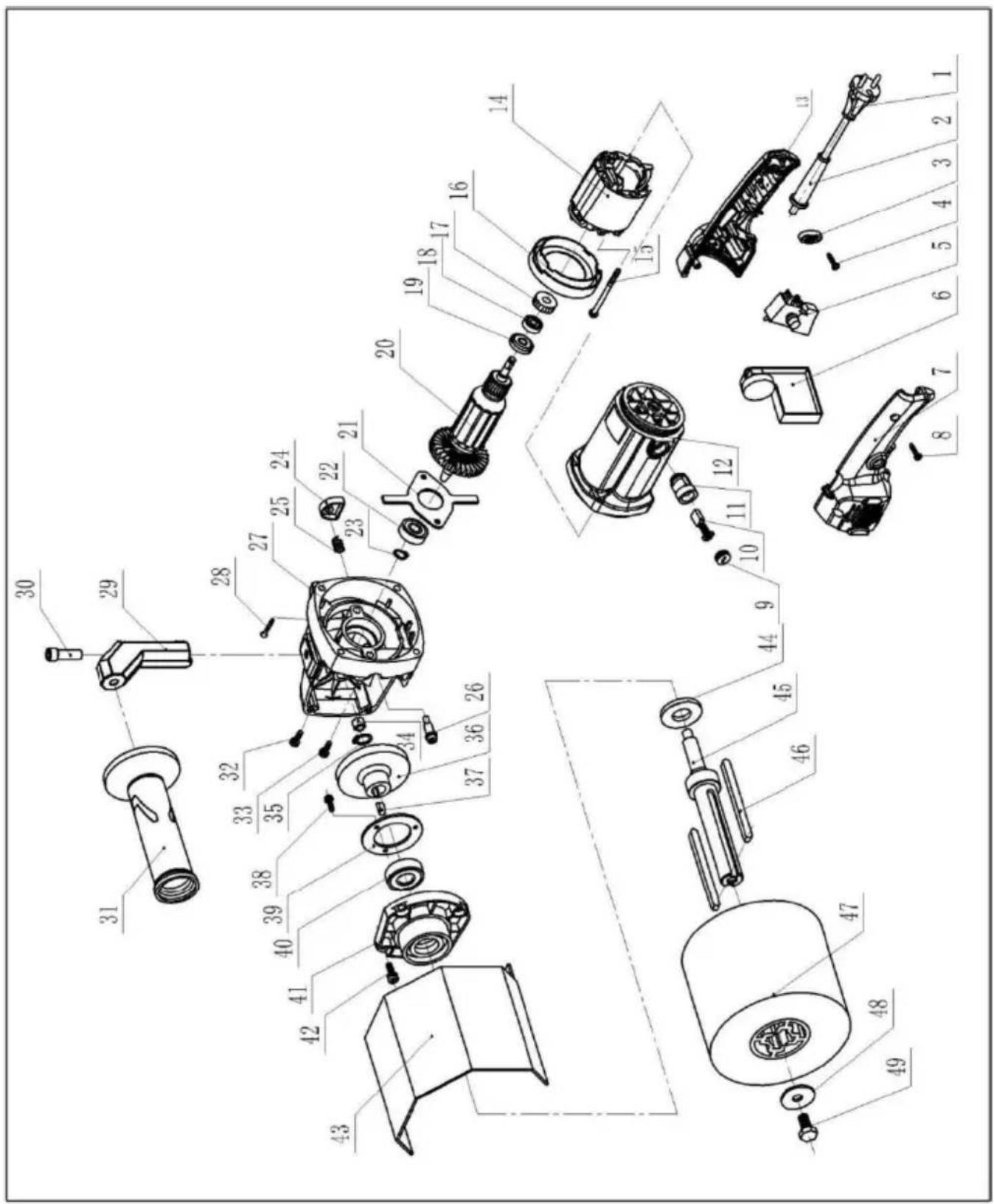
| P. NO. | PARTS NAME | Q'TY | P.No. | PARTS NAME | Q'TY |
| 1 | Electric wire | 1 | 26 | Self-locking pin | 1 |
| 2 | bushing | 1 | 27 | Reducer housing | 1 |
| 3 | Wire clip | 1 | 28 | ST5X30 screws | 2 |
| 4 | ST4X14 screws | 2 | 29 | Connecting bracket | 1 |
| 5 | Switch | 1 | 30 | M8X20 hex socket bc | 1 |
| 6 | Electronic governor | 1 | 31 | Straight handle | 1 |
| 7 | Right hand handle | 1 | 32 | M5X16 screws | 1 |
| 8 | ST4X16 screws | 4 | 33 | M5X12 screws | 1 |
| 9 | Carbon brush cap | 2 | 34 | HK0810 Needle roller bearings | 1 |
| 10 | Carbon brush | 2 | 35 | Ø12 shaft circlip | 1 |
| 11 | Brush carrier | 2 | 36 | Gear wheel | 3 |
| 12 | Housing | 1 | 37 | 4x13 semicircular key | 1 |
| 13 | Left hand handle | 1 | 38 | M4X10 screw | 1 |
| 14 | stator | 1 | 39 | 6201 bearing gland | 1 |
| 15 | ST5x65 screws | 2 | 40 | 6201 bearing | 4 |
| 16 | windshield | 1 | 41 | Output front cover | 1 |
| 17 | Rubber sleeve | 1 | 42 | M5X14 screws | 1 |
| 18 | 608 bearing | 1 | 43 | Protective cover | 1 |
| 19 | Creepage stop ring | 1 | 44 | Dust cover | 2 |
| 20 | rotor | 1 | 45 | Output shaft | 1 |
| 21 | Cross gland | 1 | 46 | 6x6x90 square key | 1 |
| 22 | 6201 bearing cross gland | 1 | 47 | Fiber wheel | 1 |
| 23 | Ø12 shaft circlip | 1 | 48 | Ø8 Flat pad | |
| 24 | Self-locking cover | 1 | 49 | M8X16 hexagonal screws | |
| 25 | Self-locking spring | 1 |
Correct Disposal

This product is subject to the provision of european Directive 2012/19 The symbol showing a wheelie bin crossed through indicates that the product requires separate refuse collection in the European Union. Th applies to the product and all accessories marked with this symbol. Products marked as such may not be discarded with normal domestic waste, but must taken to acollection point for recycling electrical and electronic devices.
Manufacturer: Shanghaimuxinmuyeyouxiangongsi
Address: Shuangchenglu 803nong11hao1602A-1609shi, baoshanqu, shanghai 200000 CN.
Imported to AUS: SIHAO PTY LTD. 1 ROKEVA STREETEASTWOOD NSW 2122 Australia
Imported to USA: Sanven Technology Ltd. Suite 250, 9166 Anaheim Place, Rancho Cucamonga, CA 91730
| UK | REP |
YH CONSULTING LIMITED.
C/O YH Consulting Limited Office 147,
Centurion House, London Road,
Staines-upon-Thames, Surrey, TW18 4AX
| EC | REP |
E-CrossStu GmbH
Mainzer Landstr.69, 60329 Frankfurt am Ma
VEVOR®
TOUGH TOOLS, HALF PRICE
Technical Support and E-Warranty Certificate
www.vevor.com/support
VEVOR®
TOUGH TOOLS, HALF PRICE
natural_image
Technical line drawing of a mechanical device with gears and shafts (no text or symbols)BESOIN D'AIDE? CONTACTEZ-NOUS!

- Interrupteur
C/O YH Consulting Limited Bureau 147,
Staines-upon-Thames, Surrey, TW18 4AX

E-CrossStu GmbH
natural_image
Technical line drawing of a mechanical device with gears and shafts (no text or symbols)
C/O YH Consulting Limited Office 147,
Centurion House, London Road,
Staines-upon-Thames, Surrey, TW18 4AX

www.vevor.com/support
VEVOR®
TOUGH TOOLS, HALF PRICE
natural_image
Technical line drawing of a mechanical device with gears and shafts (no text or symbols)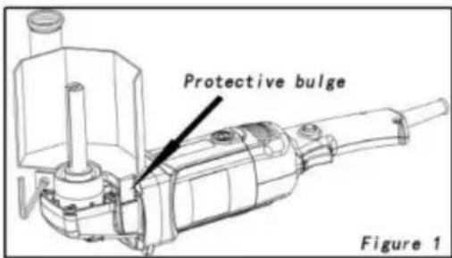
- Cambia
Importato in AUS: SIHAO PTY LTD. 1 ROKEVA STREETEASTWOOD NSW
2122 Australia
Importato negli USA: Sanven Technology Ltd. Suite 250, 9166 Anaheim Place, Rancho Cucamonga,
CA 91730

CONSULENZA YH LIMITATA.
C/O YH Consulting Limited Ufficio 147,
Casa del centurione, London Road,
Staines-upon-Thames, Surrey, TW18 4AX

elettronica www.vevor.com/support
VEVOR®
TOUGH TOOLS, HALF PRICE
natural_image
Technical line drawing of a mechanical device with cylindrical components and a handle (no text or symbols)
- Cambiar
Casa Centurión, London Road,
Staines-upon-Thames, Surrey, TW18 4AX

E-CrossStu GmbH
natural_image
Technical line drawing of a mechanical device with cylindrical components and a handle (no text or symbols)POTRZEBUJESZ POMOCY? SKONTAKTUJ SIĘ Z NAMI!

- Przełącznik
C/O YH Consulting Limited Biuro 147,
Dom Centuriona, London Road,
Staines-upon-Thames, Surrey, TW18 4AX
| Przedstawiciel UE |
E-CrossStu GmbH
Mainzer Landstr.69, 60329 Frankfurt nad Menem.
VEVOR®
TOUGH TOOLS, HALF PRICE
natural_image
Technical line drawing of a mechanical device with cylindrical components and a handle (no text or symbols)HULP NODIG? NEEM CONTACT MET ONS OP!
• Schakelaar
| P. NR. | ONDERDEELNAAM | HOEVEELHEID P.N9 | ONDERDEELNAAM | AANTAL | |
| 1 | Elektrische draad | 1 | 26 | Zelfborgende pen | 1 |
| 2 | bus | 1 | 27 | Reductiebehuizing | 1 |
| 3 | Draadklem | 1 | 28 ST5X30-schroeven | 2 | |
| 4 | ST4X14 schroeven | 2 | 29 | Verbindingsbeugel | 1 |
| 5 | Schakelaar | 1 | 30 M8X20 inbusbout | 1 | |
| 6 | Elektronische regelaar | 1 | 31 | Rechte handgreep | 1 |
| 7 | Rechterhandgreep | 1 | 32 M5X16-schroeven | 1 | |
| 8 | ST4X16 schroeven | 4 | 33 M5X12-schroeven | 1 | |
| 9 | Koolborstelkap | 2 | 34 | HK0810 Naaldrol lagers | 1 |
| 10 | Koolborstel | 2 | 35 ∅12 asborgring | 1 | |
| 11 | Borsteldrager | 2 | 36 | Tandwiel | 3 |
| 12 | Huisvesting | 1 | 37 4x13 halfronde sleutel | 1 | |
| 13 | Linkerhandgreep | 1 | 38 M4X10 schroef | 1 | |
| 14 | stator | 1 | 39 | 6201 lager pakking | 1 |
| 15 ST5x65 schroeven | 2 | 40 | 6201 lager | 4 | |
| 16 | voorruit | 1 | 41 | Uitvoer voorklep | 1 |
| 17 | Rubberen huls | 1 | 42 M5X14-schroeven | 1 | |
| 18 | 608 lager | 1 | 43 | Beschermhoes | 1 |
| 19 | Kruipstopring | 1 | 44 | Stofkap | 2 |
| 20 rotor | 1 | 45 | Uitgaande as | 1 | |
| 21 | Kruisklier | 1 | 46 | 6x6x90 vierkante sleutel | 1 |
| 22 | 6201 dragend kruis klier | 1 | 47 | Vezelwiel | 1 |
| 23 ∅12 asborgring | 1 | 48 ∅8 | Vlakke pad | ||
| 24 Zelfborgende afdekking | 1 | 49 | M8X16 zeshoekig schroeven | ||
| 25 Zelfborgende veer | 1 | ||||
C/O YH Consulting Limited Kantoor 147,
Centurionhuis, Londen Road,
Staines-upon-Thames, Surrey, TW18 4AX

E-CrossStu GmbH
Mainzer Landstr.69, 60329 Frankfurt am Main.
VEVOR®
TOUGH TOOLS, HALF PRICE
garantiecertificaat www.vevor.com/support
VEVOR®
TOUGH TOOLS, HALF PRICE
natural_image
Technical line drawing of a mechanical device with gears and shafts (no text or symbols)BEHÖVER HJÄLP? KONTAKTA OSS!
• Växla
C/O YH Consulting Limited Office 147,
Centurion House, London Road,
Staines-upon-Thames, Surrey, TW18 4AX
| EC | REP |
E-CrossStu GmbH
Mainzer Landstr.69, 60329 Frankfurt am Main.
VEVOR®
TOUGH TOOLS, HALF PRICE
www.vevor.com/support