
HD-50 - Welding tool Vevor - Free user manual and instructions
Find the device manual for free HD-50 Vevor in PDF.
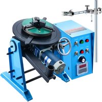


| Brand | Vevor |
| Model | HD-50 |
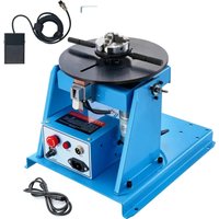
| Product Type | Welding positioner (welding turntable) |
| Power Supply | 120 V~60 Hz or 230 V~50 Hz |
| Horizontal Load Capacity | 50 kg |
| Vertical Load Capacity | 25 kg |
| Work Table Diameter | 400 mm |
| Work Table Height | 520 mm |
| Table Tilt Angle | 0° to 90° |
| Table Rotation Speed | 0.5 to 6 rpm |
| Rotary Motor Power | 120 W |
| Accepted Cable Section | 30 to 50 mm² |
| Table Center Hole Diameter | 25 mm |
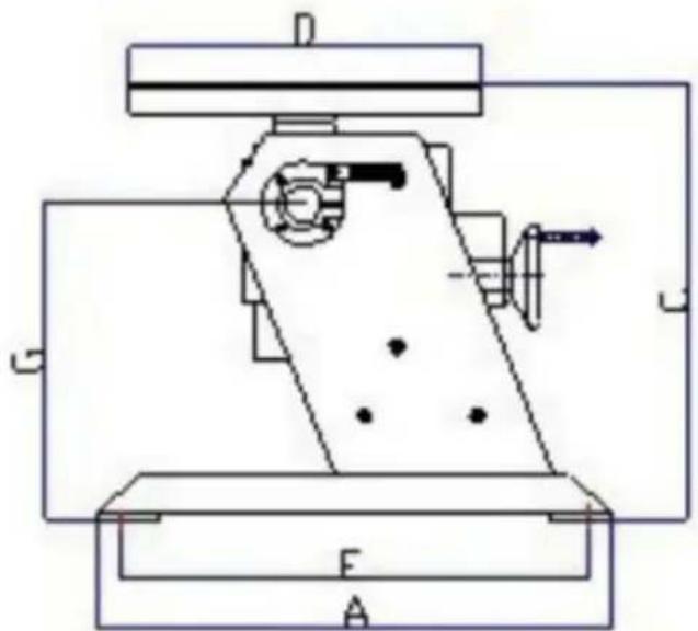
| Dimensions (E x F) | 340 mm x 320 mm |
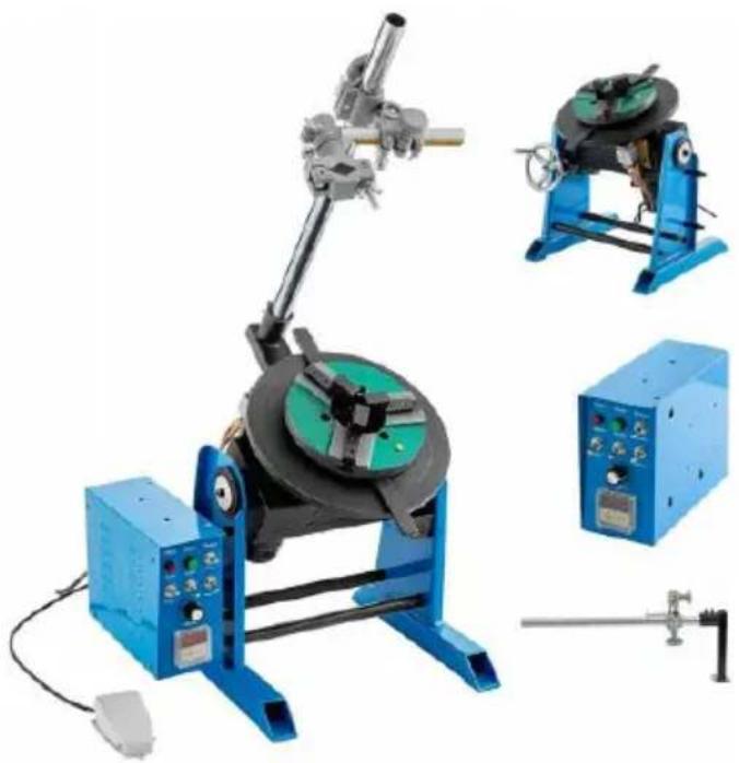
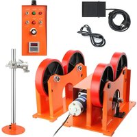
| Included Accessories | Power cord, foot switch, hand wheel, control box, aerial connection with plug, torch holder set, torch support, M8x20 mounting bolts |
| Forward/Reverse Switch | Yes (K2) |
| Speed Adjustment | Potentiometer K4 |
| Lubrication | Weekly through the lubrication hole |
| Safety | Protective equipment (gloves, helmet, goggles) mandatory; do not weld in flammable atmospheres; turn off before maintenance |
| Electromagnetic Compatibility | Complies with FCC Part 15 (Class B) |
| Warranty and Support | Electronic warranty certificate available at www.vevor.com/support |
Frequently Asked Questions - HD-50 Vevor
User questions about HD-50 Vevor
0 question about this device. Answer the ones you know or ask your own.
Ask a new question about this device
Download the instructions for your Welding tool in PDF format for free! Find your manual HD-50 - Vevor and take your electronic device back in hand. On this page are published all the documents necessary for the use of your device. HD-50 by Vevor.
USER MANUAL HD-50 Vevor
Technical Support and E-Warranty Certificate www.vevor.com/support
WELDING POSITIONER
MODEL: HD-30/HD-50
We continue to be committed to providing you with tools at competitive prices. "Save Half", "Half Price", or any other similar expressions used by us represent an estimate of savings you might benefit from buying certain tools with us compared to the major top brands and does not necessarily mean to cover all categories of tools offered by us. You are kindly reminded to verify carefully when you are placing an order with us if you are actually saving half in comparison with the top major brands.
MODEL: HD-30/HD-50
NEED HELP? CONTACT US!
Have product questions? Need technical support? Please feel free to contact us:
Technical Support and E-Warranty Certificate www.vevor.com/support
This is the original instruction. Please read all manual instructions carefully before operating. VEVOR reserves a clear interpretation of the user manual. The appearance of the product shall be subject to the product you received. Please forgive us that we won't inform you of any technology or software updates on our product.
 | Warning-To reduce the risk of injury, user must read instructions manual carefully. |
 | CORRECT DISPOSALThis product is subject to the provision of European Directive 2012/19/EC. The symbol showing a wheelie bin crossed through indicates that the product requires separate refuse collection in t European Union. This applies to the product and all accessories marked with this symbol. Products marked as such may not be discarded with normal domestic waste, but must be taken to a collection point for recycling electrical and electronic devices |
IMPORTANT SAFEGUARDS

WARNING: A procedure, which, if not properly followed, may cause injury to the operator or others in the operating area.
Equipment Identification
The identification number, specification or model, and serial number of this unit usually appear on a nameplate attached to the control panel. Record these numbers for future reference.
Receipt of Equipment
When you receive the equipment, check it against the shipping documents. Make sure it is complete and inspect the equipment for possible damage during shipping. If there is any damage, notify the carrier immediately to file a claim.
Provide complete information regarding damage claims or errors in shipment to Machinery Co., Ltd. Include the equipment identification number along with a description of the parts in question.
Move the equipment to the installation site before uncrating the unit. Use care to avoid damaging the equipment when using bars, hammers, etc. to uncrate the unit.
General safety rules:
Before removing the body of the product, pull out the wire first.
The operator must be qualified accordingly.
The operation can only be controlled by qualified technicians.
The compressed air power must be cut off and turned off before the maintenance operation is carried out.
Electrodes, electrode arms and other secondary conductors can reach very high temperatures and stay high for a long time after stopping the machine. Pay attention to scald.
Preventive maintenance is necessary on a regular basis.
Power Connection:
- Check that the device must be connected to the ground coupler and to the ground. It is in good condition.
- Check if the workbench is connected to the ground connector.
- Ensure that the operator does not have any contact, protection or wet clothing with the metal parts to be welded.
- Avoid contact with welded parts.
- Do not spot weld in very wet places or on wet floors.
- Do not weld with worn cables. Check that the insulation is not damaged and that connections are not loose.
- Turn off the device before replacing the electrode.
- Disconnect the equipment before servicing or repairing it.
Protection of Eyes and Body:
- During welding, wear leather gloves, a welding apron, safety shoes, welding protective clothing, and a helmet or glasses with arc filtering and radiation protection. The operator must protect their eyes during chipping and hammering.
- Do not wear rings, watches, or jewelry. They can cause burns.
- All protective shields must be in good condition and in proper position. Without eye protection, do not look at the welding arc. Protect the area near the product from sparks and reflections.
Welding Fume:
Welding operations can produce toxic fumes and harmful metal dust. The equipment should be installed in covered areas with fume extractors. Operators must wear respirators. Welding materials must be clean.
Fire Safety:
- Check that sparks do not cause fires, especially near flammable materials.
- Ensure that a fire extinguisher is within easy reach of the operator.
- Place the equipment in an area with proper ventilation.
- Do not weld on a container with flammable and lubricant, even if it is empty.
- Do not weld in an atmosphere filled with flammable gas or fuel vapor.
Electromagnetic Compatibility:
Near the welding site, check:
- There are no other power cords, control cables, telephone lines, radio or television reception equipment, watches, mobile phones, magnetic cards, computers or any other electronic device.
- No active medical devices (pacemakers, acoustic prostheses) were used around (at least 3 meters).
FCC Information:
- CAUTION: Changes or modifications not expressly approved by the party responsible for compliance could void the user's authority to operate the equipment!
This device complies with Part 15 of the FCC Rules. Operation is subject to the following two conditions:
1) This product may cause harmful interference. 2) This product must accept any interference received, including interference that may cause undesired operation. - WARNING: Changes or modifications to this product not expressly approved by the party responsible for compliance could void the user's authority to operate the product. - Note: This product has been tested and found to comply with the limits for a Class B digital device pursuant to Part 15 of the FCC Rules. These limits are designed to provide reasonable protection against harmful interference in a residential installation.
This product generates, uses and can radiate radio frequency energy, and if not installed and used in accordance with the instructions, may cause harmful interference to radio communications. However, there is no guarantee that interference will not occur in a particular installation. If this product does cause harmful interference to radio or television reception, which can be determined by turning the product off and on, the user is encouraged to try to correct the interference by one or more of the following measures.
- Reorient or relocate the receiving antenna.
- Increase the distance between the product and receiver.
- Connect the product to an outlet on a circuit different from that to which the receiver is connected.
- Consult the dealer or an experienced radio/TV technician for assistance.
| Model | HD-30 | HD-50 |
| Power input | AC120V/60Hz; AC230V/50Hz | AC120V/60Hz; AC230V/50Hz |
| Horizontal loading capacity | 30KG | 50KG |
| Vertical loading capacity | 15KG | 25KG |
| Working table diameter | 315mm | 400mm |
| Working table height | 380mm | 520mm |
| Working table tilting angle | 0-90° | 0-90° |
| Working table rotation speed | 1-12RPM | 0.5-6RPM |
| Rotation motor | 80W | 120W |
| Cable terminal | 30-50mm2 | 30-50mm2 |
| Table Centre Through Hole D | 25mm | 25mm |
| Accessories | Power cord *1foot switch *1,hand wheel *1,control box *1connecting aviationplug *1set of gun holder (with rod) *1,gun holder holder *1,manual *1,Mounting bolts*4(M8*20 stud, flat pads, spring pads) | Power cord *1foot switch *1,hand wheel *1,control box *1connecting aviationplug *1set of gun holder (with rod) *1,gun holder holder *1,manual *1,mounting bolts*4(M8*20 stud, flat pads, spring pads) |
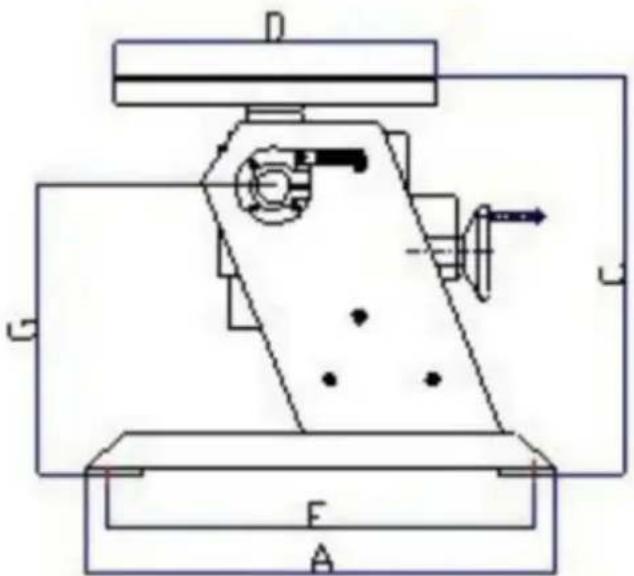
DIMENSIONS
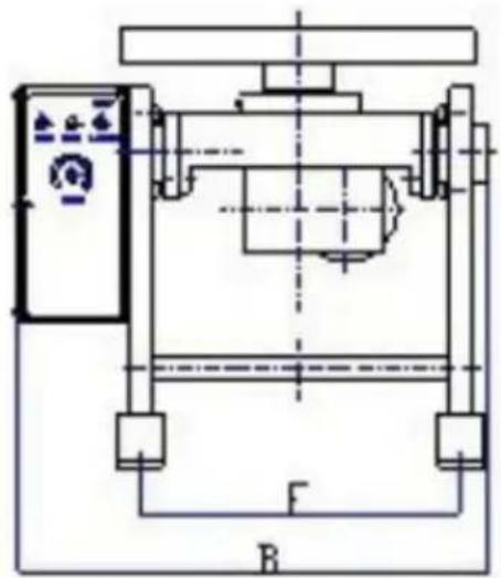
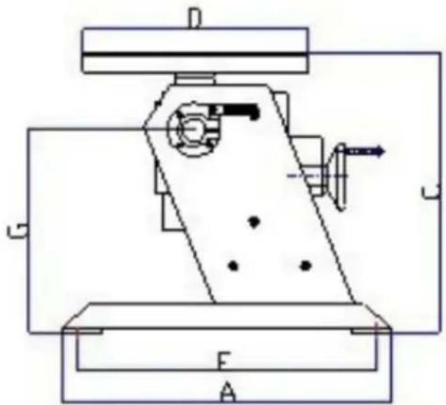
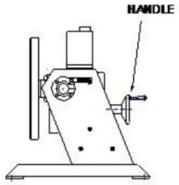
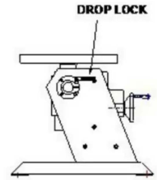
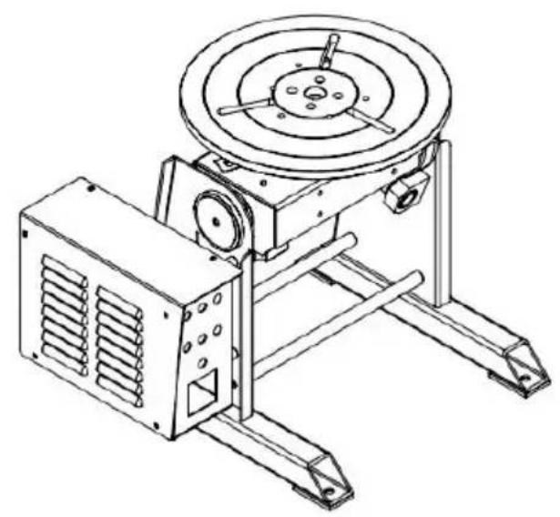
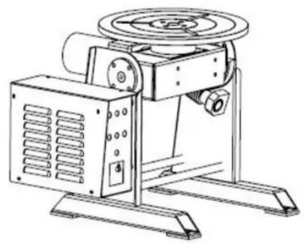
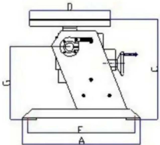
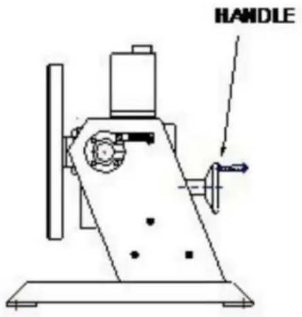
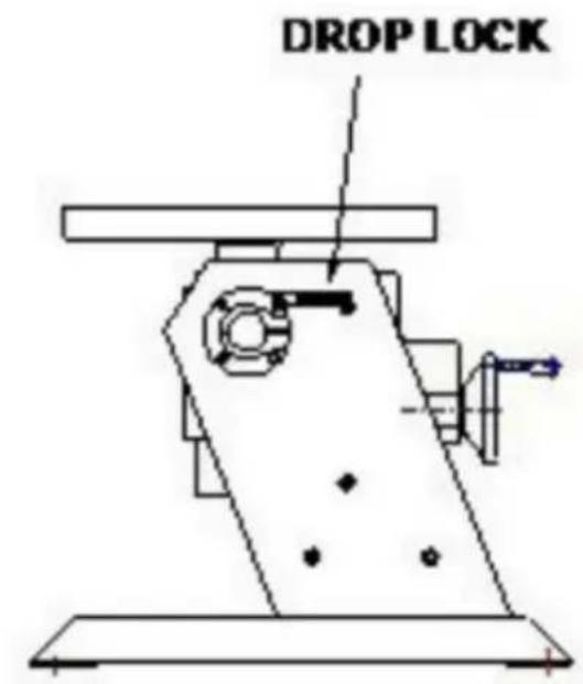
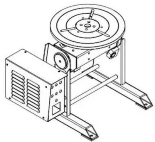
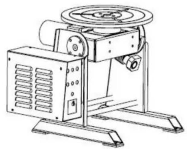
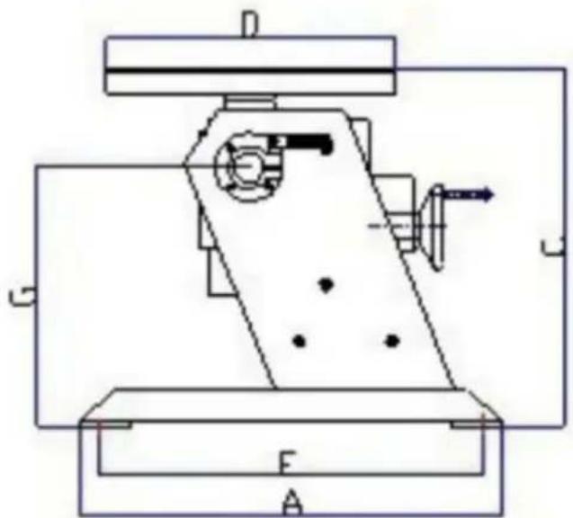
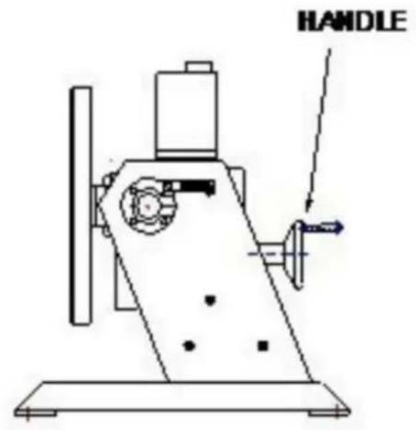
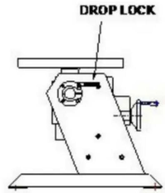
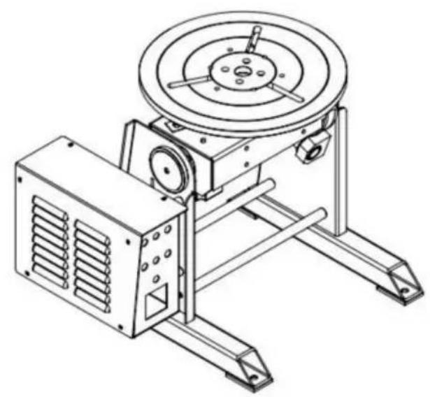
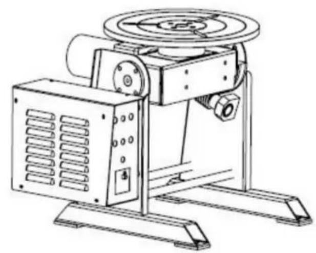
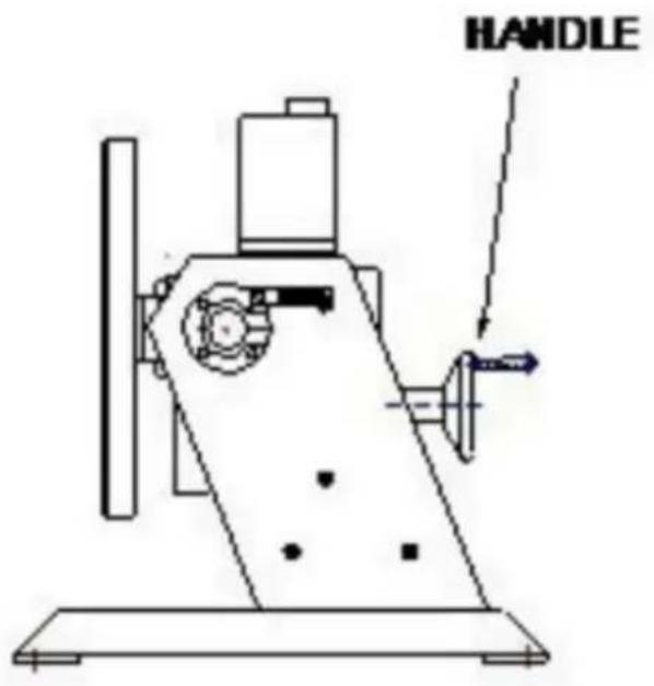
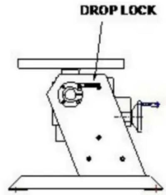
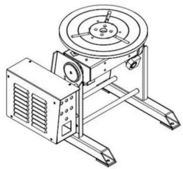
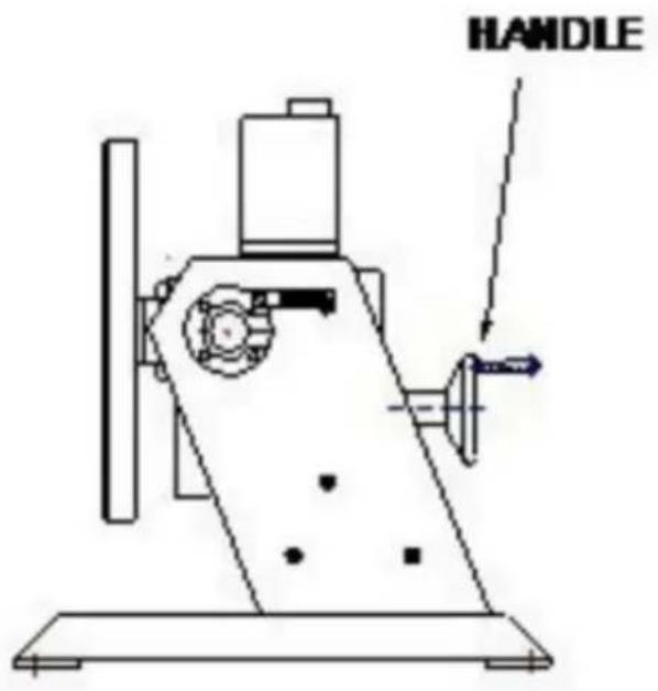
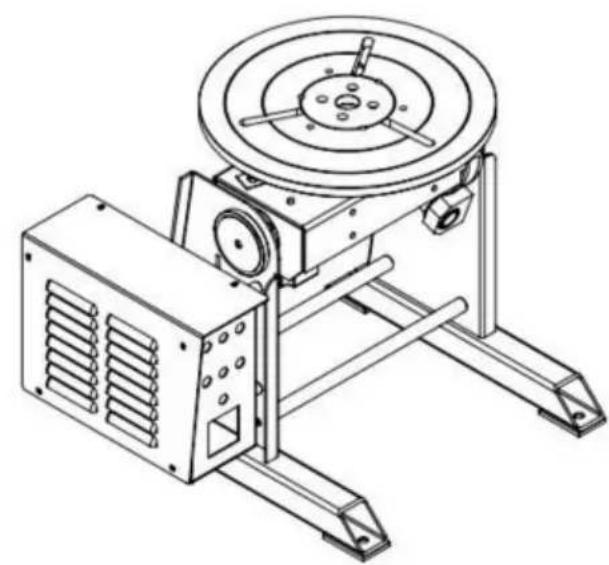
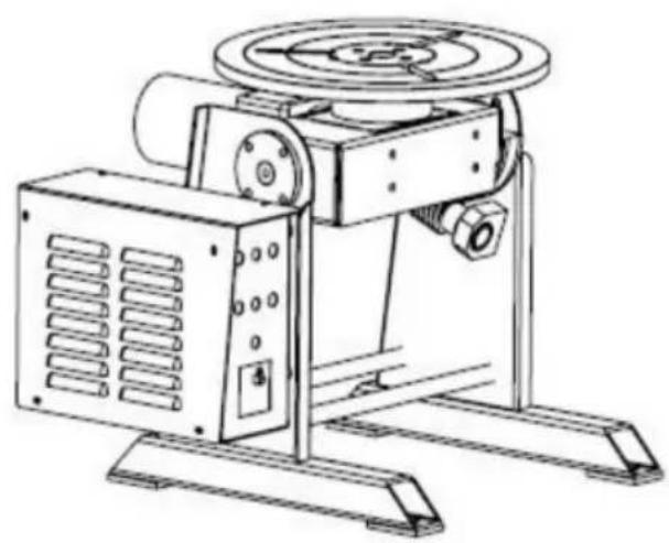
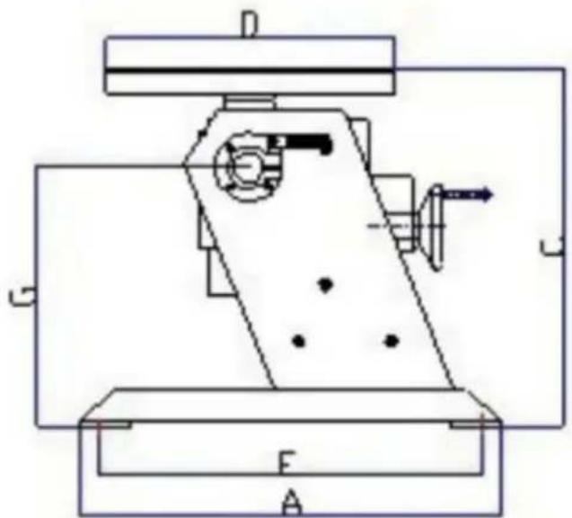
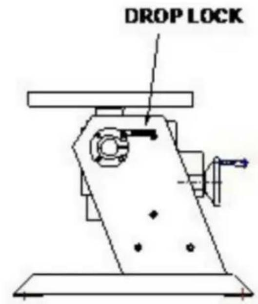
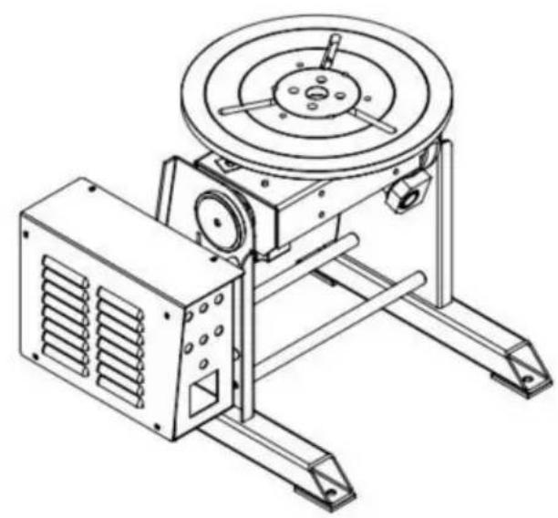
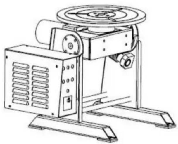
HD-30 Schematic diagram HD-50 (120W) Schematic diagram NOTE:
- HD-50: E=340mm F=320 mm
- LUBE HOLE: Pour lubricating oil per week.
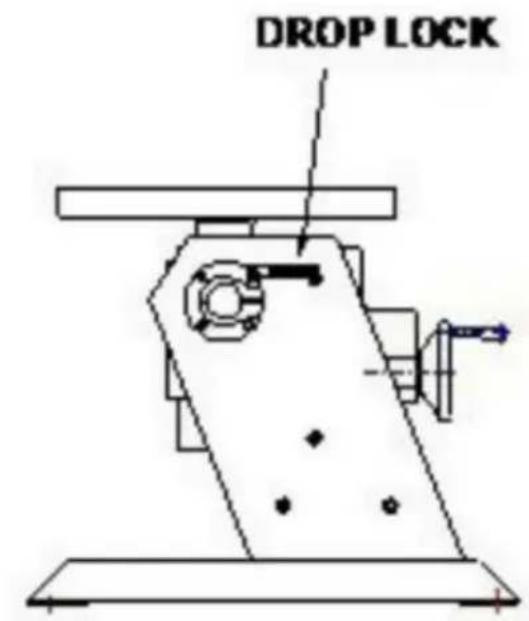
- DROP LOCK: Holding locking screw tightly when choose working table angle.
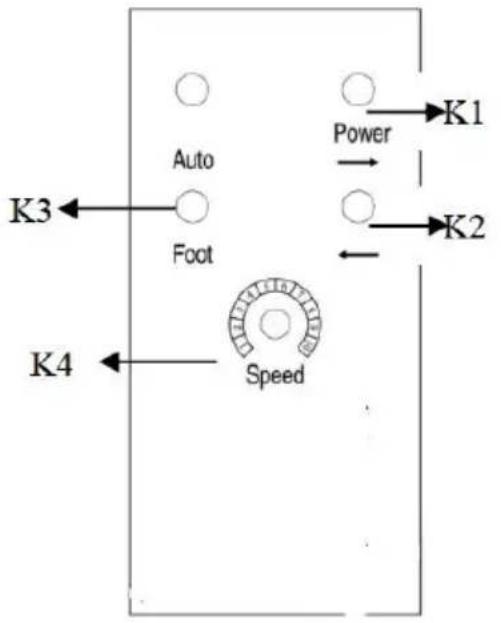
FRONT PANEL:
K1: POWER ON/OFF SWITCH
K2: FORWARD/REVERSE SWITCH
K3: POWER PILOT
K4: SPEED ADJUSTMENT
TROUBLE SHOOTING GUIDE
| NO. | SYMPTOM | POSSIBLE CAUSE | REMEDY |
| 1 | Power pilot does not lit | 1. Power fuse is burnt.2. LED burnt.3. Power switch is burnt.4. No power input. | 1. Replace a new fuse.2. Replace LED.3. Replace switch.4. Check the switch or replace. |
| 2 | Speed Adjustment no Motion. | 1. Damaged potentiometer.2. Motor control PCB no output. | 1. Check if potentiometer is 10KΩ, otherwise replace2. Replace a new motor control PCB. |
| 3 | Foot switch no motion | Foot switch is damaged. | Check the foot switch or replace. |
| 4 | Forward/Reverse no output | Forward/Reverse switch is damaged. | Check the switch or replace. |
| 5 | Motor no motion | 1. Motor has power input but no motion.2. Motor control PCB has no power input3. Motor control PCB is damaged. | 1. Replace a new motor.2. Check the transformer o replace.3. Replace control PCB. |
ILLUSTRATION OF THE CONTROL PCB ADJUSTMENT
- Attention when choose the switches of input and output voltage, disconnect the power timely when doing the switch.
- ACCEL is time accelerating adjustable potentiometer
When the output voltage is 0-90VDC, from 0.5 seconds to 11 seconds can be adjustable;
When the output voltage is 0-180VDC, the time can be adjusted from 0.5 seconds to 22 seconds.
- DECEL is the decelerating adjustable potentiometer.
When the output voltage is 0-90 VDC, the longest time is 13 seconds; when the output voltage is 0-180VDC, the longest time is 25 seconds.
- MAX SPD is the maximum speed adjustable potentiometer;
Twist it clockwise to the end to set the maximum speed.
- MIN SPD is the minimum speed adjustable potentiometer;
Twist it clockwise to the end to set the zero speed anticlockwise.
- INHIBIT is the external enable control side,
When this function works, the speed of the motor is set by MIN SPD.
- TORQUE \ IRCOMP are the torque and laden adjustable potentiometers.
CONTROL SCHEMATIC DIAGRAM
![graph TD A["AC20V INPUT (Aci AC2)"] --> B["Motor Armature Power (A1 + A2)"] B --> C["DC output"] C --> D["Motor Armature Voltage (A1 + A2)"] D --> E["Switch Circuit"] E --> F["SYNCH RONOS Signal"] F --> G["RAMature Voltage Calculation (THRISTOR) Trigger Circuit"] G --> H["Control Board (Drive Board)…](/content/2026/04/735936/images/ee6fda69a7cb47d8ba15da7c7df613a1ece535fad0da3dc5aa23fdc26f052129.jpg)
VEVOR®
TOUGH TOOLS, HALF PRICE
Technical Support and E-Warranty Certificate
www.vevor.com/support
Made In China
VEVOR®
TOUGH TOOLS, HALF PRICE
NEED HELP? CONTACT US!
FRONT PANEL:
K1: ON/OFF SWITCH
NEED HELP? CONTACT US!
FRONT PANEL:
K1: ON/OFF SWITCH
www.vevor.com/support
NEED HELP? CONTACT US!

HD-50 120W Schematic Diagram
NOTE:
FRONT PANEL:
www.vevor.com/support Made in China
VEVOR®
TOUGH TOOLS, HALF PRICE
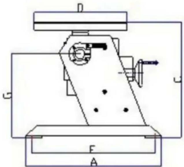
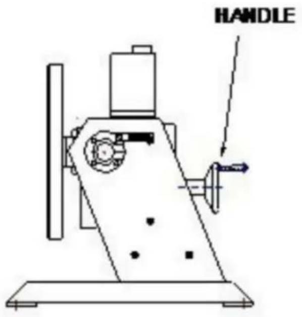
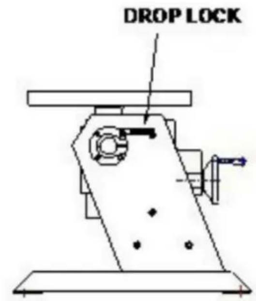
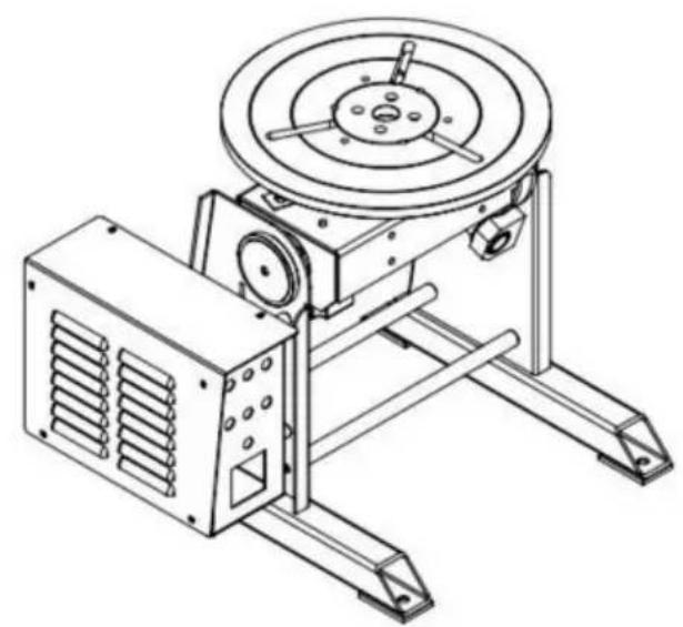
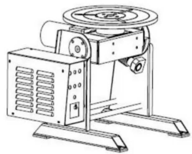
HD-30 Schematic Diagram NOTE: HD-50 120W Schematic Diagram
FRONT PANEL:
K1: ON/OFF SWITCH
K2: FORWARD/REVERSE SWITCH
NEED HELP? CONTACT US!
FRONT PANEL:
K1: POWER ON/OFF SWITCH
www.vevor.com/support
NEED HELP? CONTACT US!
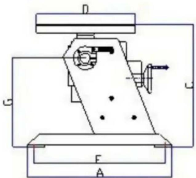
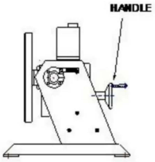
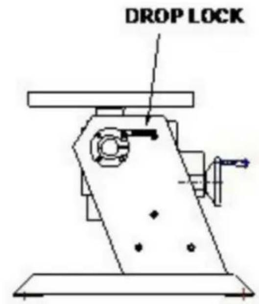
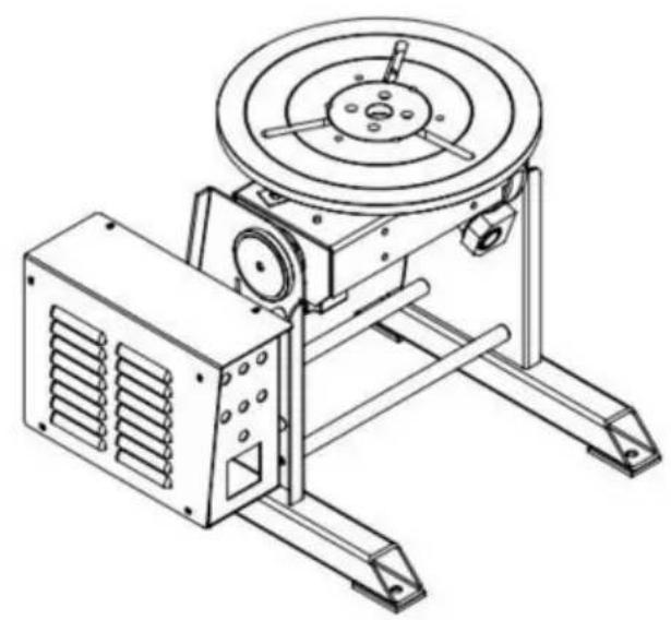
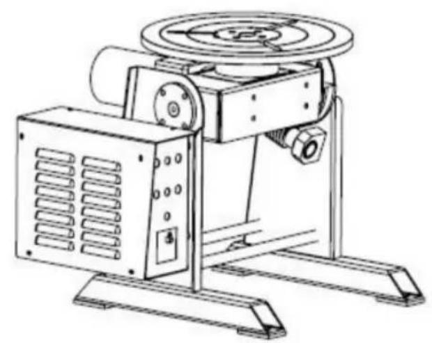
HD-30 Schematic diagram HD-50 120W Schematic diagram
NOTE:
- HD-50: E=340mm F=320mm
- LUBRICATION HOLE: Pour lubricating oil weekly.
- DROP LOCK: Hold the locking screw firmly when choosing the worktable angle.
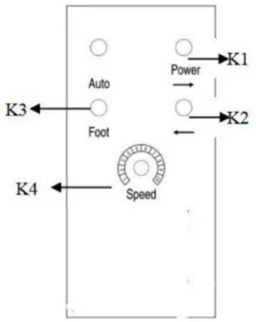
FRONT PANEL:
K1: ON/OFF SWITCH
K2: FORWARD/REVERSE SWITCH
K3: POWER PILOT
K4: SPEED ADJUSTMENT
TROUBLESHOOTING GUIDE
NEED HELP? CONTACT US!

FRONT PANEL:
K1: POWER ON/OFF SWITCH K2: FORWARD/REVERSE SWITCH K3: POWER PILOT K4: SPEED ADJUSTMENT
TROUBLESHOOTING GUIDE
www.vevor.com/support
Made in China
- WELDING POSITIONER
- MODEL: HD-30/HD
- NEED HELP? CONTACT US
- IMPORTANT SAFEGUARDS
- EQUIPMENT IDENTIFICATION
- RECEIPT OF EQUIPMENT
- GENERAL SAFETY RULES
- POWER CONNECTION
- PROTECTION OF EYES AND BODY
- WELDING FUME
- FIRE SAFETY
- ELECTROMAGNETIC COMPATIBILITY
- NEAR THE WELDING SITE, CHECK
- FCC INFORMATION
- DIMENSIONS
- HD-30 SCHEMATIC DIAGRAM HD-50 (120W) SCHEMATIC DIAGRAM NOTE
- FRONT PANEL
- TROUBLE SHOOTING GUIDE
- ILLUSTRATION OF THE CONTROL PCB ADJUSTMENT
- CONTROL SCHEMATIC DIAGRAM
- VEVOR®
- TOUGH TOOLS, HALF PRICE
- NOTE
- TROUBLESHOOTING GUIDE
Brand : Vevor
Model : HD-50
Category : Welding tool