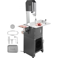
JG-250 - Saw Vevor - Free user manual and instructions
Find the device manual for free JG-250 Vevor in PDF.


| Product type | Bone saw with integrated meat grinder |
| Brand | Vevor |
| Model | JG-250 |
| Power supply | 220-240 V AC (check the nameplate) |
| Main functions | Bone cutting, meat grinding |
| Saw blade | Steel, adjustable in tension and position |
| Work table | With rails and guide wheels, adjustable |
| Protection | Height-adjustable protective cover |
| Safety | Star switch, red stop button, grounding |
| Maintenance | Cleaning after use, oiling of rust-prone parts |
| Included accessories | Meat grinder, pusher, guide, rubber feet |
| Belt | V-belt with tension adjustment |
| Material | Steel body, rubber feet |
| Certification | CE (Directive 2012/19/EU) |
| Warranty | Electronic warranty certificate via www.vevor.com/support |
Frequently Asked Questions - JG-250 Vevor
User questions about JG-250 Vevor
0 question about this device. Answer the ones you know or ask your own.
Ask a new question about this device
Download the instructions for your Saw in PDF format for free! Find your manual JG-250 - Vevor and take your electronic device back in hand. On this page are published all the documents necessary for the use of your device. JG-250 by Vevor.
USER MANUAL JG-250 Vevor
Technical Support and E-Warranty Certificate www.vevor.com/support
BONE SAW MACHINE
MODEL: JG-250
We continue to be committed to provide you tools with competitive price. "Save Half", "Half Price" or any other similar expressions used by us only represent of savings you might benefit from buying certain tools with us compared top brands and doses not necessarily mean to cover all categories of tools offered are kindly reminded to verify carefully when you are placing an order with us actually saving half in comparison with the top major brands.
VEVOR®
BONE SAW MACHINI
MODEL:JG-250
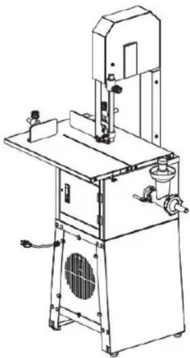
natural_image
Technical line drawing of a mechanical device with no visible text or symbolsNEED HELP? CONTACT US!
Have product questions? Need technical support? Please feel from contact us:
Technical Support and E-Warranty Certificate www.vevor.com/support
This is the original instruction, please read all manual instruction carefully before operating. VEVOR reserves a clear interpretation user manual. The appearance of the product shall be subject to product you received. Please forgive us that we won't inform your use there are any technology or software updates on our product
 | Warning-To reduce the risk of injury, user must re instructions manual carefully. |
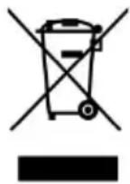 | CORRECT DISPOSALThis product is subject to the provision of European 12012/19/EC. The symbol showing a wheelie bin cros through indicates that the product requires separate r collection in the European Union. This applies to the and all accessories marked with this symbol. Produ marked as such may not be discarded with normal d waste, but must be taken to a collection point for r electrical and electronic devices |
IMPORTANT SAFEGUARDS
WARNING:
Read all safety warnings, instructions, illustrations and specifications provided with this electrical appliances. Failure to follow all instructions listed below may result in electric shock, fire and/or serious injury.
- There shouldn't be anything else on the counter.
- There is no abnormal phenomenon after the power is switched on
- It must be placed on the horizontal plane to avoid danger from s back and forth during use.
-
Because the chain saw rotates at high speed, it is also necessary to develop the habit of turning off the switch when the operation is suspended. Do not plug the power cord into the socket when not in Please unplug the power cord after use and before cleaning or maintenance.
-
If iron nails or other metal items are included in the cut items, it cause jagged cracks or damage. So, please pay attention to the cutti surface during operation to ensure workplace safety.
-
Please unplug the power of the machine before cleaning, assembling
disassembling.
- Do not place the product within reach of children. Children should supervised to ensure they do not play with the appliance.
- This appliance can be used by children aged from 8 years and a person with reduced physical, sensory or mental capabilities or I of experience and knowledge if they have been given supervision or instruction concerning use of the appliance in a safe way and unders the hazards involved. Children shall not play with the appliance. Clear and user maintenance shall not be made by children without supervisi
- Don't unplug the machine before it stops operation.
- If the supply cord is damaged, it must be replaced by the manu service agent, or similarly qualified persons to avoid a hazard.
- Electric Shock Danger! Non-professional personnel is forbidden to repair the products. Otherwise, it may result in electrical shock. When failures happen, they should be fixed by qualified maintenance personnel
- WARNING! Putting the main body into the water to clean is strict prohibited. It only can be scrubbed with a wet towel. The machine m thoroughly cooled before cleaning.
- Please check that the specified supply voltage in the product is consistent with the supply voltage(AC only).
- Avoid power cord damage. Do not squeeze, bend, or friction; kee away from heat sources and open fires. The power cord does not to the blade.
- Power cord should be laid fiat. Do not pull the power cord and the product fall, which may cause damage.
- Do not use the product on wet ground. Do not touch the product power cord plug with wet hands.
- Do not disassemble the product at will. Also, do not let somethir or insert into the product, which may cause damage.
- Only accessories the seller or manufacturer provides can be used the product. We will not be responsible for any failure caused by using accessories from other manufacturers not covered by warranty.
- Do not use the product on uneven, damp, not heat-resistant surface
to avoid damage or failure.
- Do not place the product directly on the fire or near the source fire. Otherwise, the product will be damaged or even result in danger
- When the plug is plugged into the socket, it must be plugged in end. Otherwise, it will cause the components to overheat and burn down poor contact.
- Do not leave the product to work with no one watching. If the I is overheating, please stop working immediately and unplug the power.
- Once part of the product is on fire, do not directly use water to extinguish the fire. Use a wet cloth to cover the fire site.
- Please store the plastic bags and not allow children to play with to prevent a risk of suffocation.
- It is prohibited to put the main body of the machine and the pc into any liquid.
- DO NOT open the case door; the hands are strictly forbidden from touching the saw blade while the machine operates.
SAVE THESE INSTRUCTIONS
Cleaning
The machine must be cleaned up after completion because the meat residue and foam attached to the body will not be hygienic for a lor. The next time you use it, the noise increases, and the saw blade is damaged.
SAW BLADE GUARD COVER
Guard cover (Fig.1B) can be moved up and downdepending on the thickness of the meat. Using theknob(A)to adjust the sawing space. P down thecover when sawing thin meat. Pull up the coverwhen sawing thick meat. It will prevent hands frombeing injured.
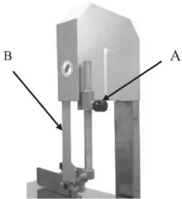
Figure 1
REMOVING THE GUARD COVER
- Loosen the screw on the front cover. Fig.2C.
- Loosen the four screws on the two sides of girder(Fig 2D) Remove cover (Fig2F).
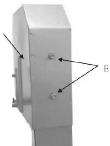
- Loosen the two screws on rear cover Fig 3E
- Remove the guard cover. Fig 3G.
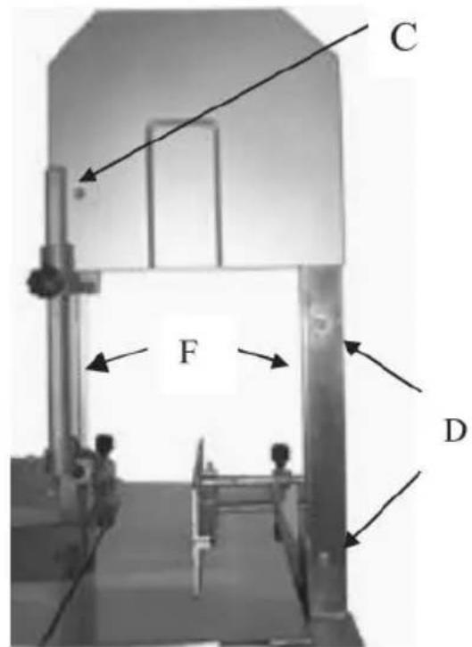
Figure 2
G
natural_image
3D diagram of a mechanical component with labeled points E and directional arrows (no text or symbols beyond labels)Figure 3
REPLACING OR ADJUSTING SAW BLADE
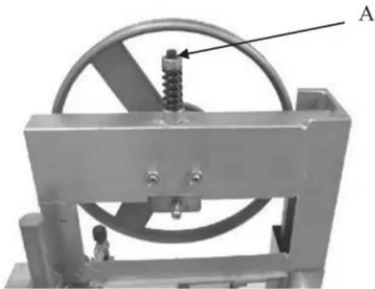
Loosen the nut as shown in the Fig 4A, then replaceor adjust the s blade.
natural_image
Mechanical device with a wheel and spring assembly, labeled 'A' (no text or symbols on the device itself)Figure 4
WORKING TABLE
To remove the table.
- Loosen the 4 screws on the table side. Fig 5A
- Take away the fix plate. Fig 6B
3.Slide the table and take off it. Fig. 6C
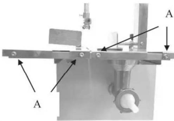
Figure 5
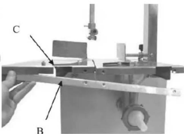
Figure 6
PUSH BUTTON
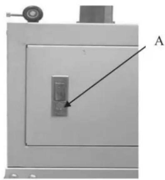
Push the red button (Fig.7A), open the door to clean,inspect, or main
after the use of meat chopper.
natural_image
Exterior view of a mechanical device with a labeled component 'A' and an arrow pointing to a vertical lock or button (no text or symbols beyond label)Figure 7
BLADE CENTERING ON WHEEL
- Loosen the screw. Fig 8A.
- Adjust the two nuts (Fig 8B) until blade trackson the wheel center
- Fasten the screws Fig8A.
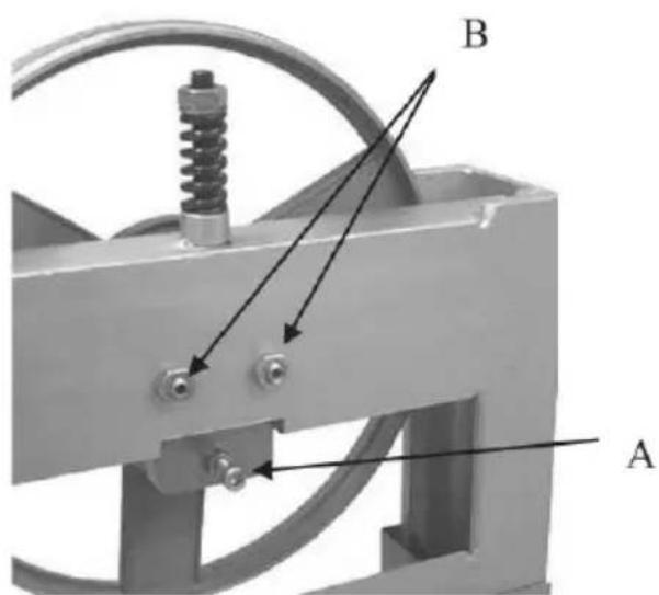
Figure 8
UPPER BLADE FIXED SEAT
After blade is vertically adjusted.
- Loosen two screws (Fig 9A), and move the two inserts (Fig 9B) to m certain space to put the saw blade into the slit of upper blade fixed
2. Tighten the screw(Fig 9A)
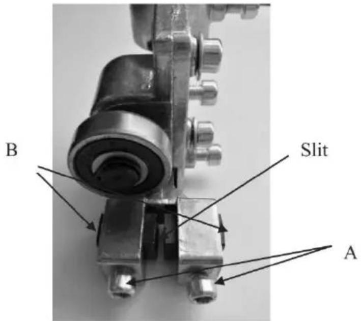
Figure 9
-
Loosen the screw (Fig 10C) to adjust the bearing position. Please measure the bearing as close as possible to the back edge of the blade. bearings should have a clearance of 1/32"with the blade. Then tighten the screw after adjustment.
-
Loosen the screw (Fig 10D) to adjust the bladeguide. Make sure blade is in the center of the slit. And re-tighten the screw (Fig 10D)

Figure 10
- After adjustment, then fix the blade guard into the bracket by tighten the two screws (Fig 10E)
LOWER BLADE FIXED SEA
TAfter the blade was adjusted vertically:
-
Loosen two screws (Fig. 1IA). to adjust the twoguide plates (Fig 1IB), make a reasonable space to put the blade into the slit. (Fig 11C)
-
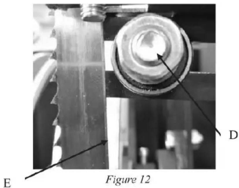
Loosen screw(Fig 12D) on the bearing.
-
Adjust the bearing position as close as possible to the back edge of blade. (Fig 12E)
-
Fast the screws again.
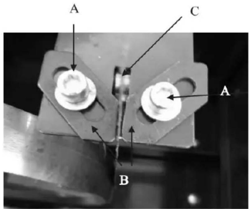
Figure 11
ASSEMBLE THE MEAT CHOPPER
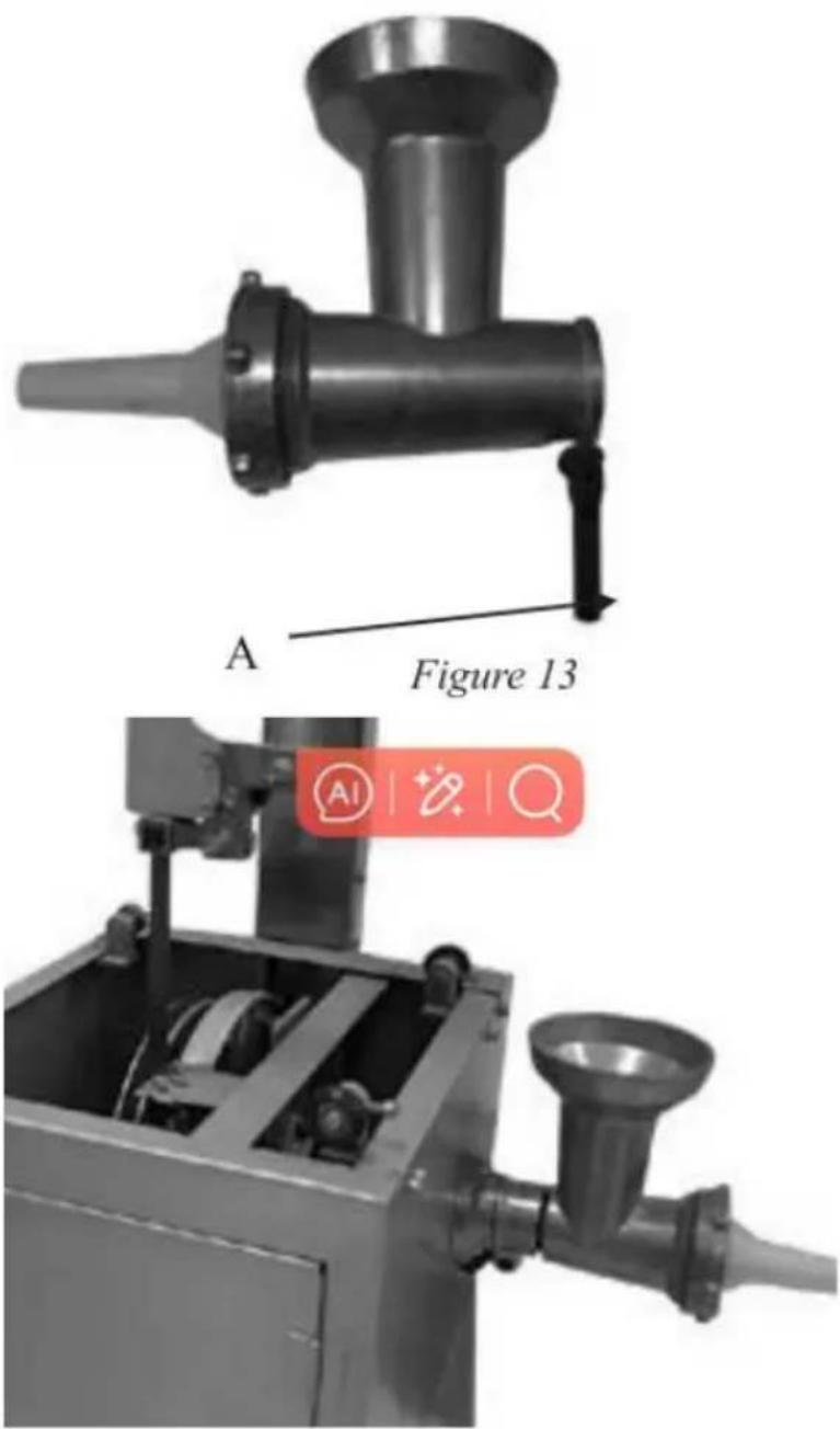
1 Loosen the handle (Fig 13A)
2 Put the body of the grinder into the seat and tighten the handle.(Fig. 1)
natural_image
Technical illustration of a manual laboring machine with labeled components and a magnified view (no text or symbols on the machinery itself)Figure 14
ASSEMBLE MACHINE TO STAND
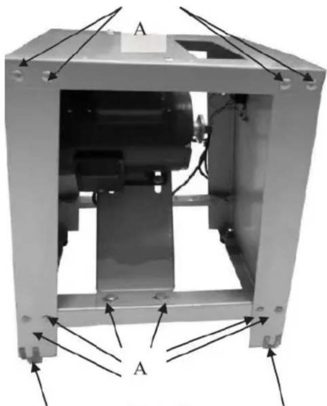
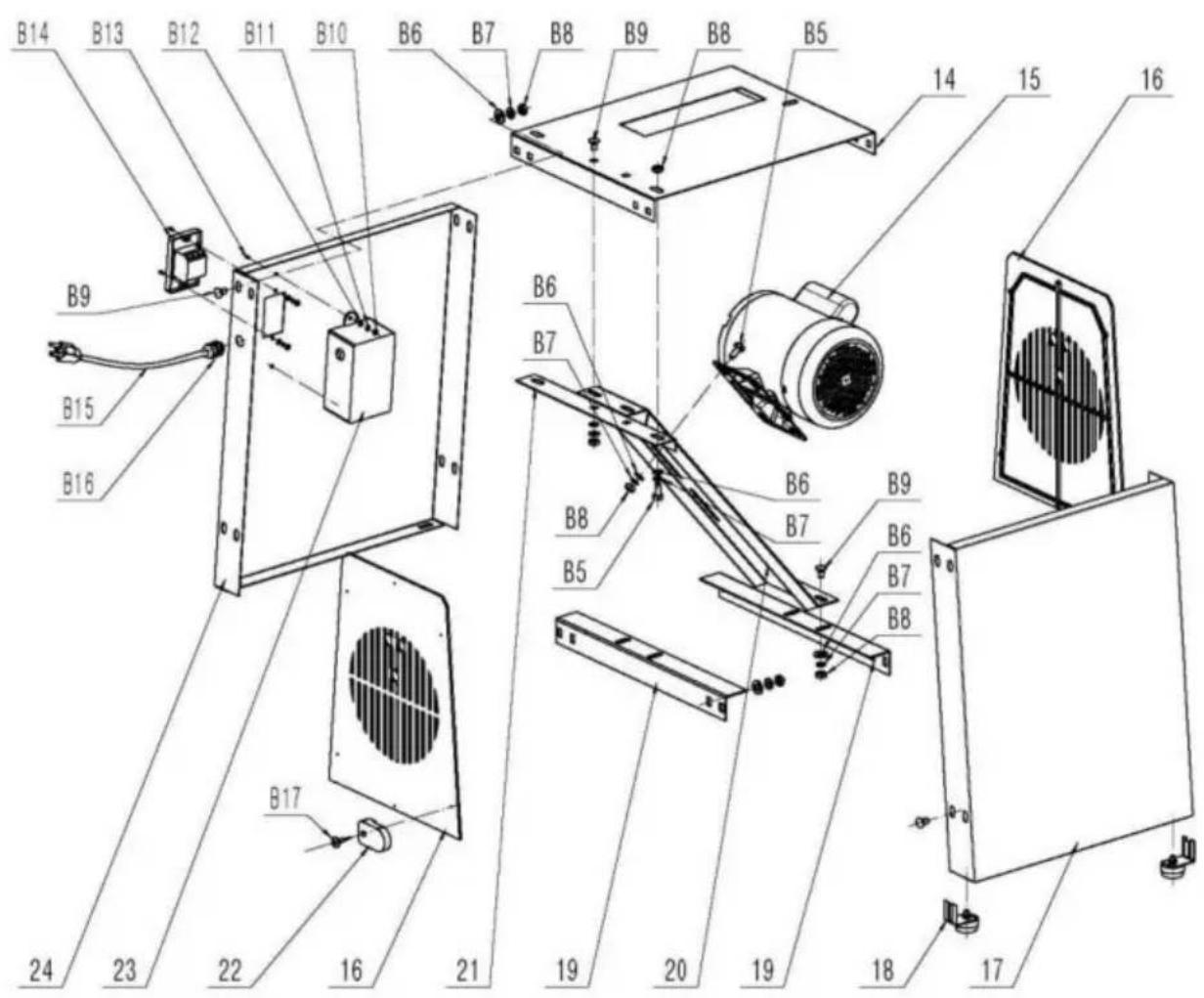
Using the screws(Fig 15A) to assemble the stand as Fig 15. And fix motor into the stand.
natural_image
Technical diagram of a mechanical assembly with labeled components A and B, showing internal components and mounting points (no text or symbols beyond labels)Figure 15
B
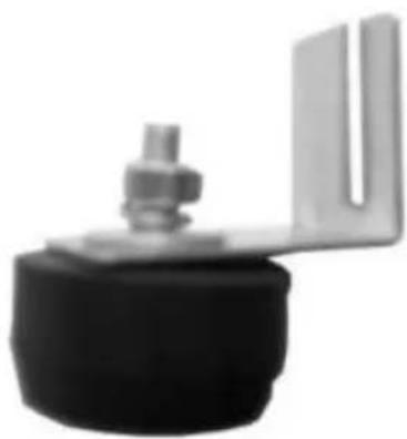
Assemble the four rubber pads (Figl6) onto the four corners (Figl5B) of the stand in order to reduce the vibration.
natural_image
Close-up of a mechanical component with a U-shaped bracket and a black base (no visible text or symbols)Figure 16
There are three elliptical holes(Fig 17A) on the top of the stand. Adjust saw body to fix the stand. And use the long bolts through the three toighten the saw body with the stand.
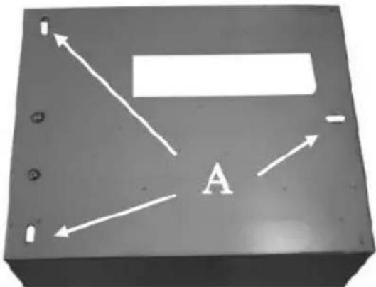
Figure 17
ADJUST VBELT
(I) Adjusting V-Belt tension.
- Put the V-Belt into the two pulleys.(Fig 18B)
- Loosen the four screws.(Fig 18A)
- Adjust the motors to the proper position.
- Fasten the four screws.
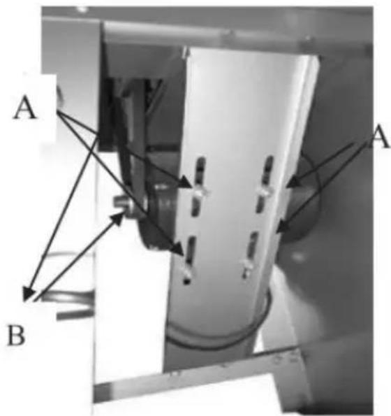
Figure 18
(II)Adjusting V-Belt vertical
In case the Vbelt is not vertical, (pulleys notaligned), loosen the two screws(Fig 19A) to adjustthe motor fixed plate. Then fasten them again
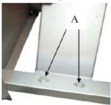
Figure 19
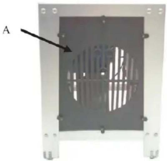
After adjusting, assemble the protection fences (Fig20A) on the stand
natural_image
Metallic device with a circular vent or grille pattern, labeled 'A' and an arrow pointing to it (no text or symbols on the device itself)Figure 20
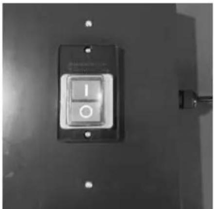
START SWITCH
The star switch is located on the upper side of the steel stand (Fig.2)
natural_image
Close-up of a black electrical switch with two buttons, mounted on a wall (no visible text or symbols)Figure 21
ASSEMBLING THE SWITCH
Fig22A shows the ground wires, it's fixed to thestand by two screws(22B). Fig22C shows the power source wires. Fig22D shows the motorpower wire.
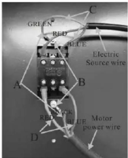
Figure 22
After connected the wires into the switch, fix theswitch box to cover switch on the stand by thetwo screws.(Fig.23D)
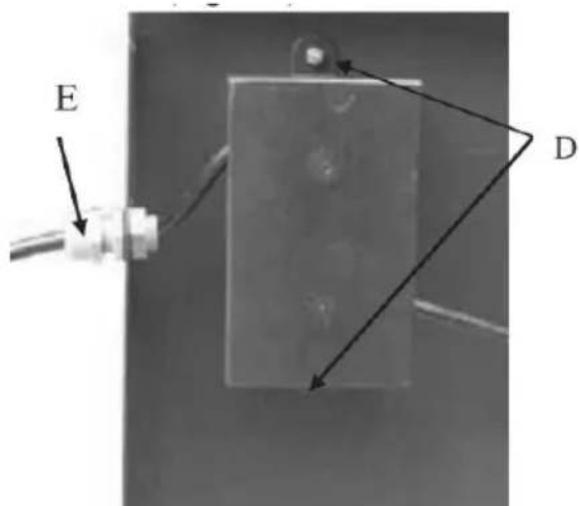
Figure 23
After fixed the switch box, please fasten the cableclamp by turn the (Fig.23E)
ASSEMBLY OF GUIDE WHEES ANDTABLE
-
Use the hex-screws(Fig 24A) to fix the fourguide wheels(Fig 24C)
-
Loose the bolt(Fig 24B) to adjust the wheelposition.
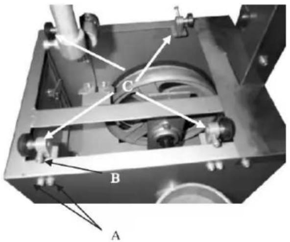
Figure 24
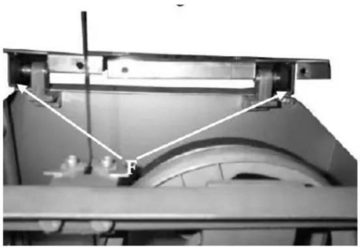
- Loosen the four screws (Fig 25D) to move the fixplate. (Fig26E)
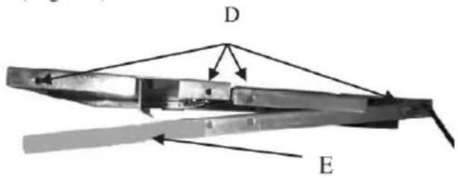
Figure 25
- Under the working table, there are two rails(Fig26F). Along the rail sliding the table, make therail move on the four guide wheels.
natural_image
Mechanical assembly diagram showing a motor frame with force vectors and a pulley (no text or symbols)Figure 26
- Use the four screws to assemble the fix plate into the table. (Fig 5A)
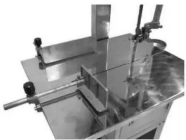
ASSEMBLY OF FENCE AND PUSHER
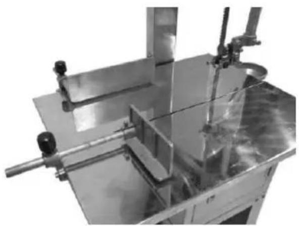
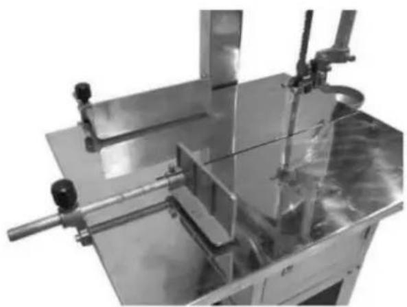
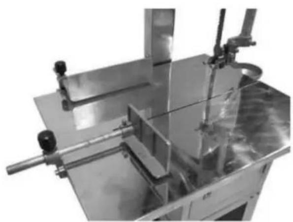
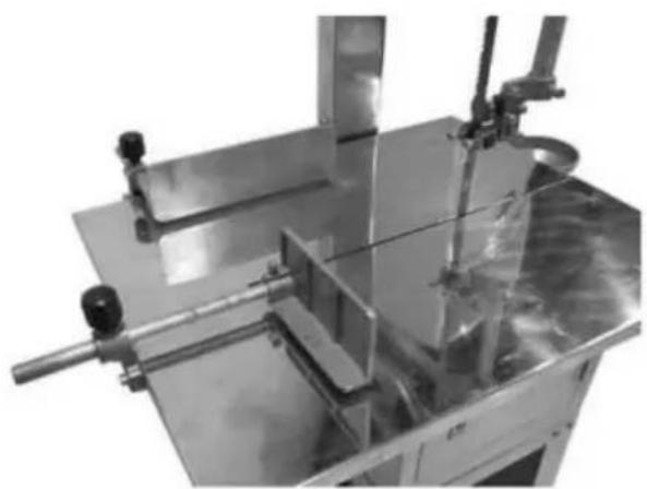
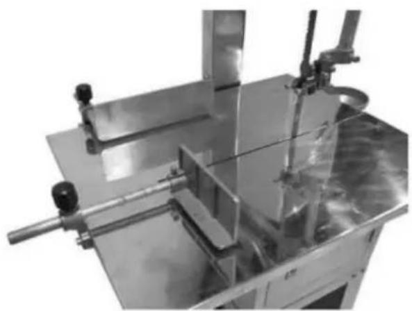
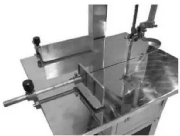
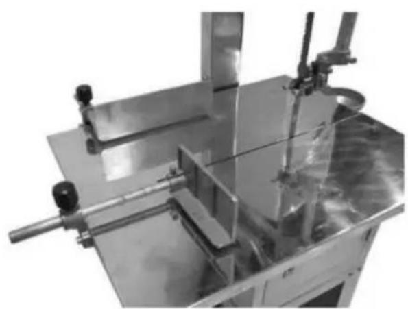
Using Fig 27 & Fig28 as a reference pictures to mount the two brack with screws.(Fig27 A) onto the working table.
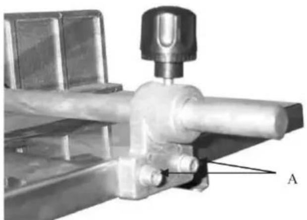
natural_image
Mechanical assembly diagram showing a valve mounted on a metal component with labeled point A (no text or symbols beyond label)Figure 27
natural_image
Industrial machine with metal frame and control lever (no visible text or symbols)Figure 28
DISASSEMBLY OF MEAT CHOPPER
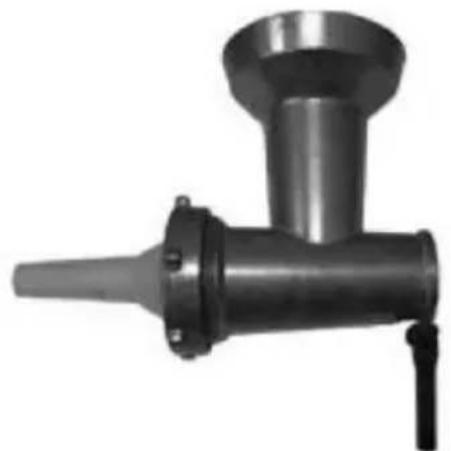
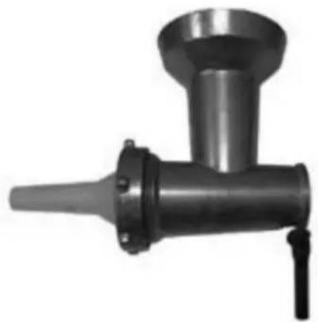
Figure 29 shows the meat chopper
natural_image
Metal mechanical component with conical shaft and flange (no visible text or symbols)Figure 29
MAINTENANCE & DAILY CLEANING
Clean the blade, table and mincer with water after using the machine.Open the guard cover for cleaning if necessary. Use feeding oil those parts that will easily become rusty in order to avoid developing rust. Keep the machine clean at all times and pay attention to the work environment to avoid accidents.
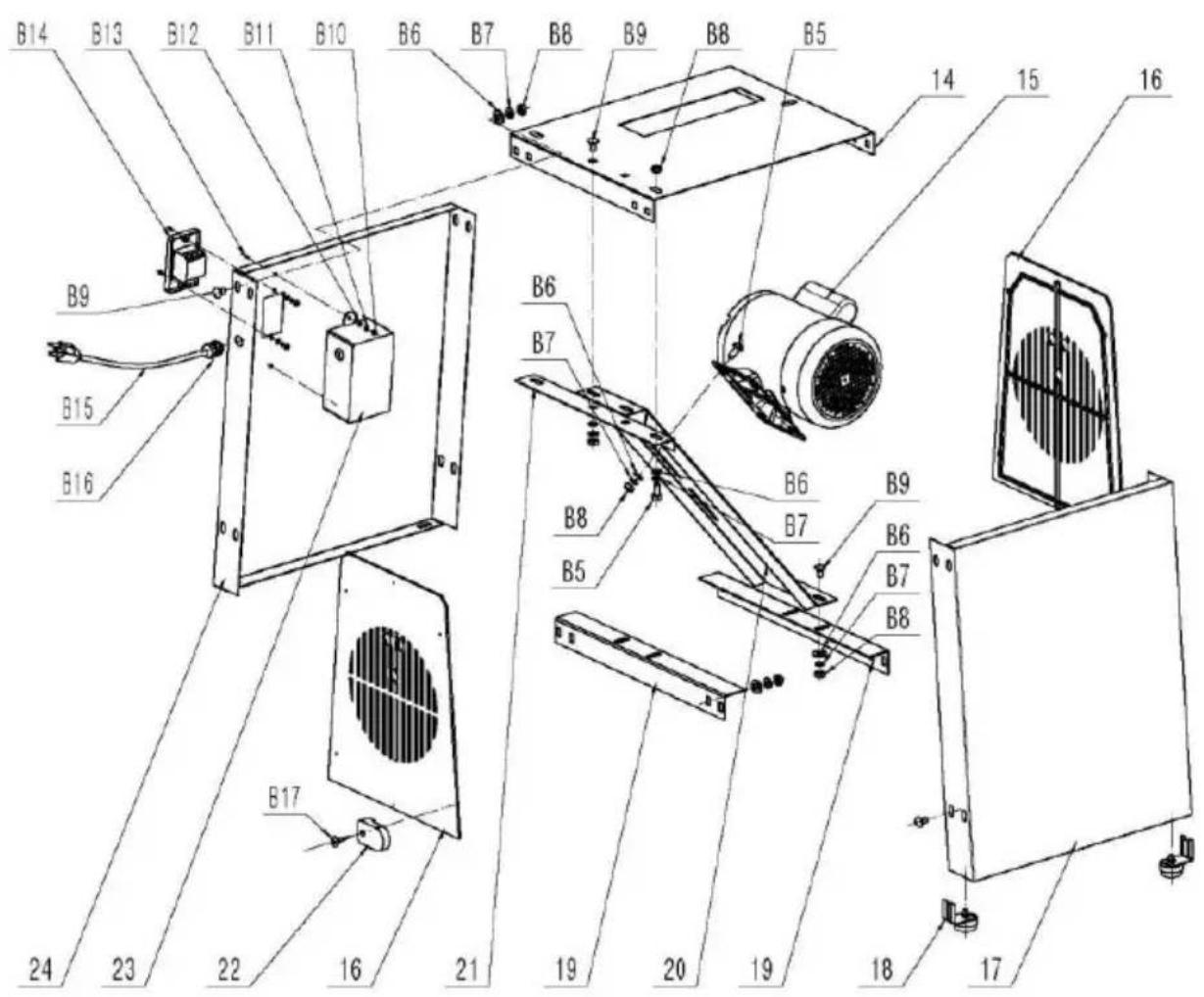
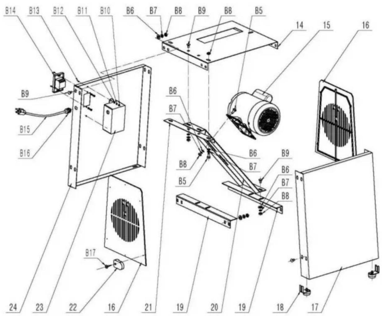
Parts List
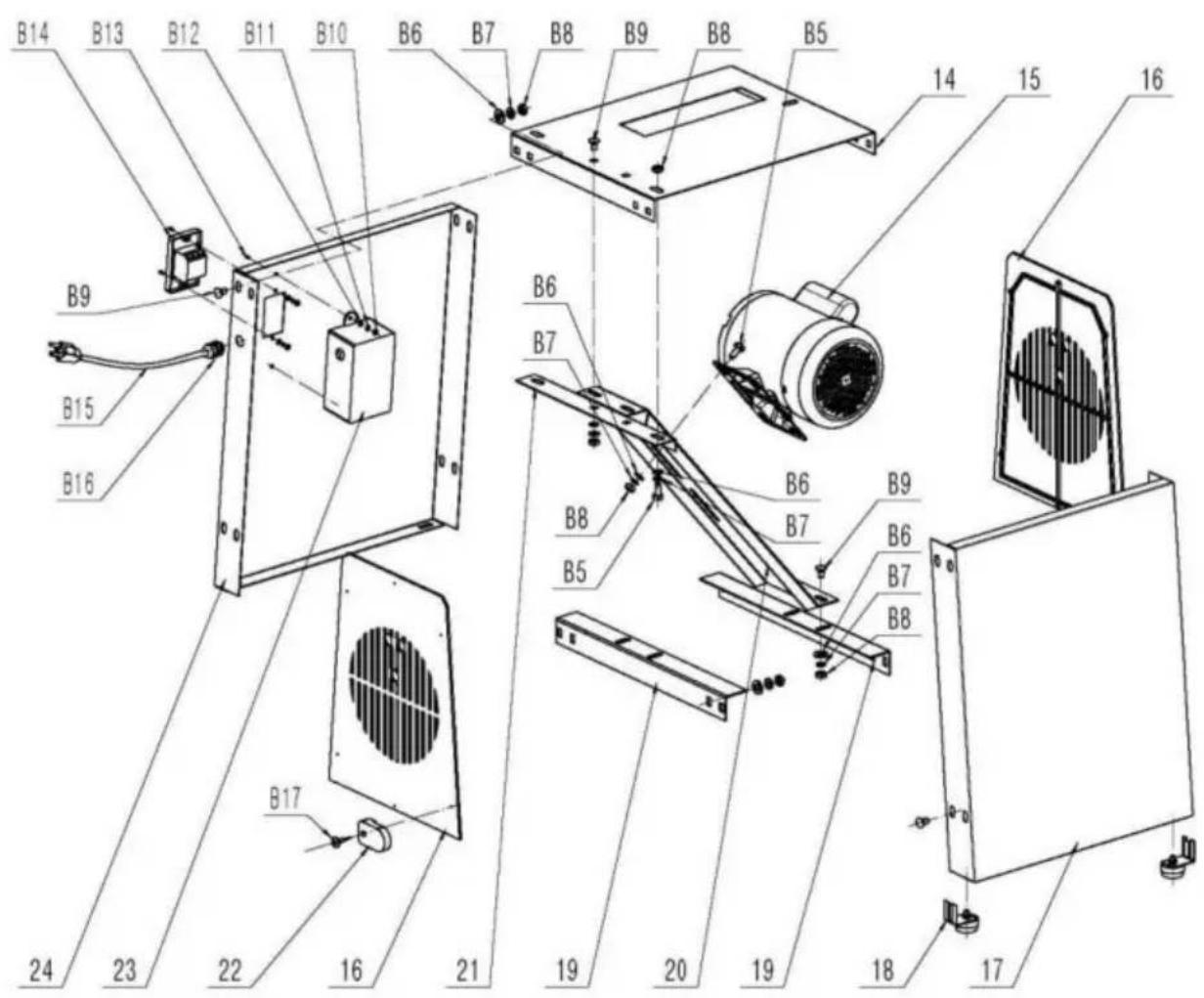
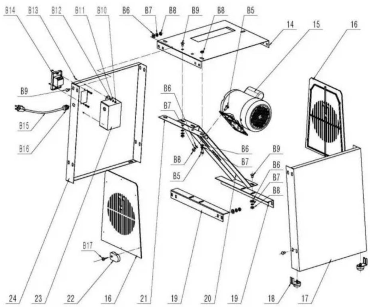
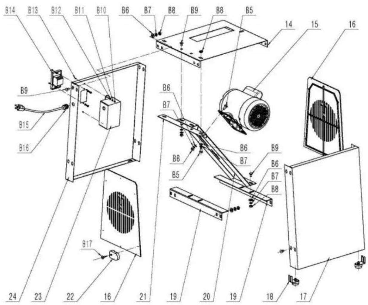
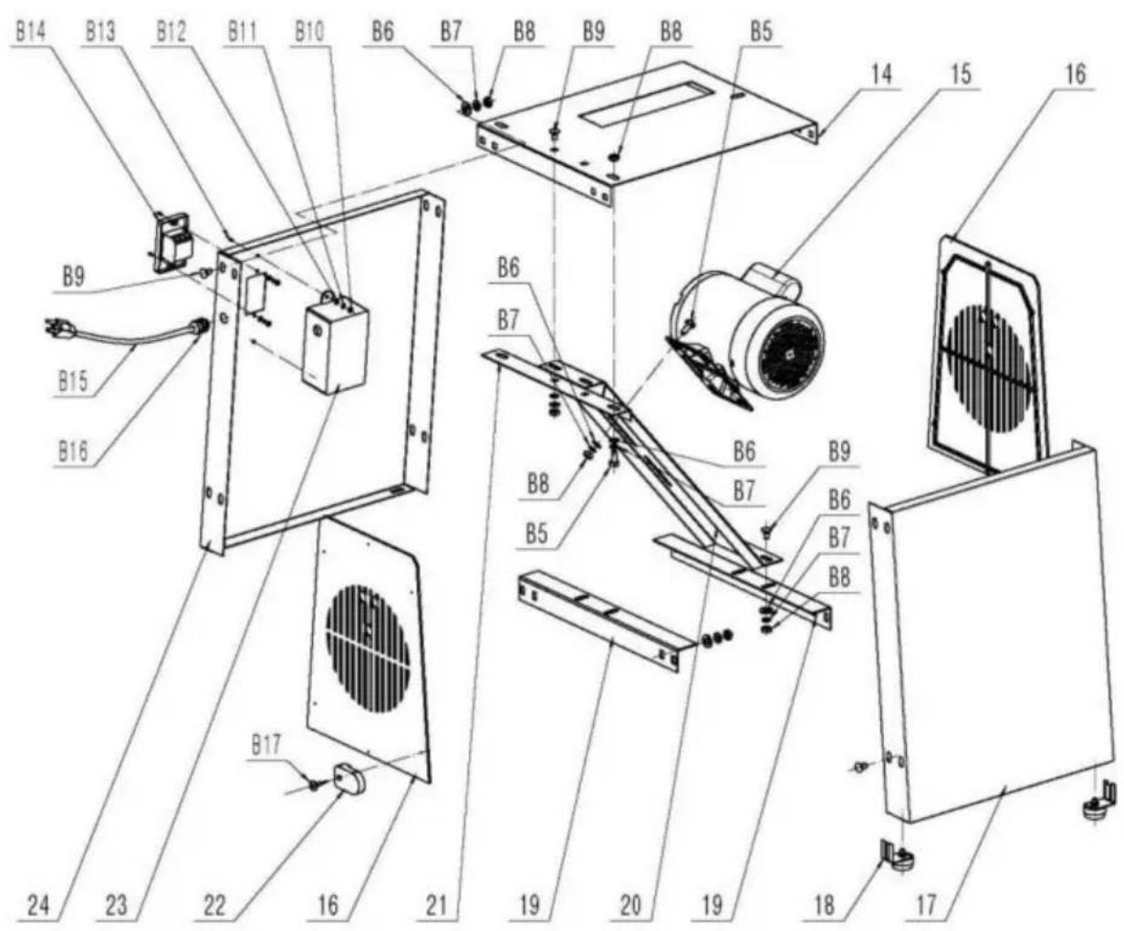
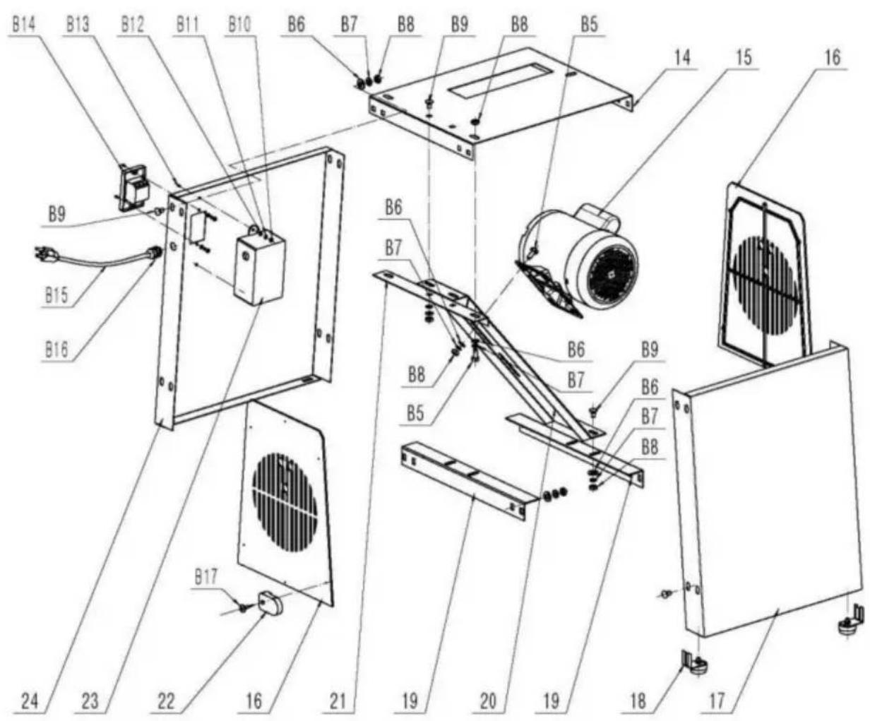
Please refer to Parts List table during assembly.
| No. | Description | Specifications | Qty. | Photo |
| 1 | Tube Connector | N/A | 1 | 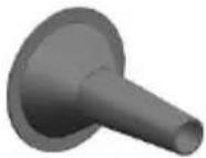 |
| 2 | Meat Grinder Body | N/A | 1 | 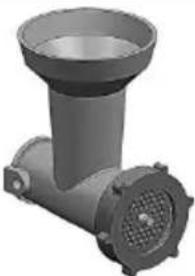 |
| 3 | Meat Grinder Locking Lever | N/A | 1 | 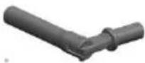 |
| 4 | Plug The Meat Stick | N/A | 1 | 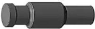 |
| 5 | Cover | N/A | 1 | 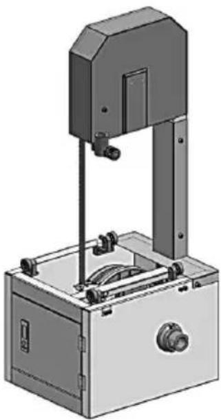 |
| 6 | Saw Blade Protection Device | N/A | 1 |  |
| 7 | Adjustable Support | N/A | 1 | 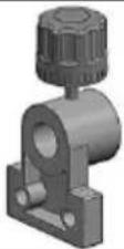 |
| 8 | Fence Guide | N/A | 1 | 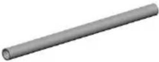 |
| 9 | Fence | N/A | 1 | 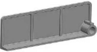 |
| 10 | Pusher Guide | N/A | 1 |  |
| 11 | Pusher | N/A | 1 |  |
| 12 | Table | N/A | 1 | 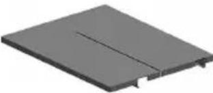 |
| 13 | Table Support | N/A | 1 | 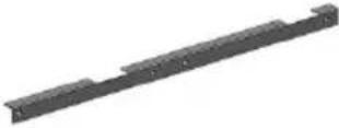 |
| 14 | Upper Cover | N/A | 1 | 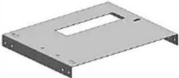 |
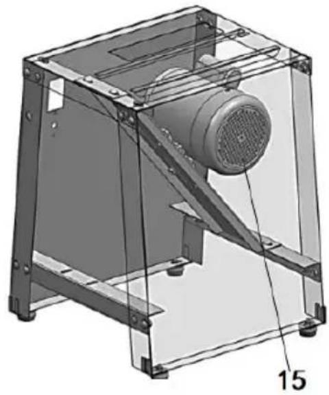
| 15 | Motor | N/A | 1 | 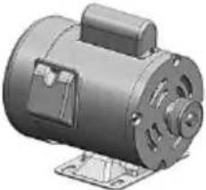 |
| 16 | Access Panel | N/A | 2 | 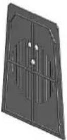 |
| 17 | Left Side Plate | N/A | 1 | 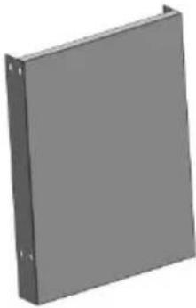 |
| 18 | Rubber Feet | N/A | 4 | 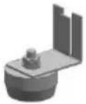 |
| 19 | Supporting Plate | N/A | 2 | 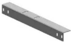 |
| 20 | Motor Support Plate | N/A | 1 | 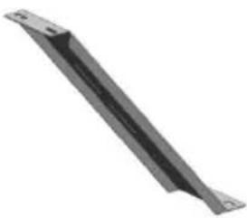 |
| 21 | Supporting Plate | N/A | 1 |  |
| 22 | Access Panel Lock | N/A | 12 |  |
| 23 | Switch Cover | N/A | 1 | 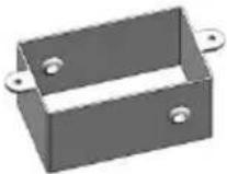 |
| 24 | Right Side Plate | N/A | 1 | 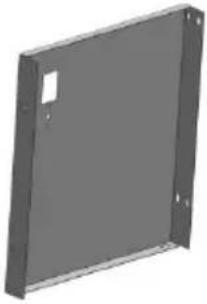 |
| B1 | Socket Screw | M6*20 | 4 | 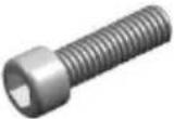 |
| B2 | Washer | 6mm | 8 | 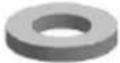 |
| B3 | Socket Screw | M4*10 | 1 |  |
| B4 | Socket Screw | M6*10 | 4 | 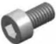 |
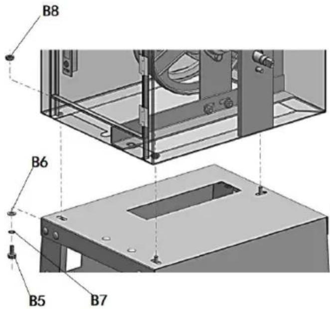
| B5 | Screw | M8*25 | 7 | 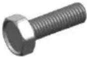 |
| B6 | Washer | 8mm | 27 | 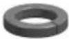 |
| B7 | Locking Washer | 8mm | 27 | 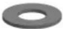 |
| B8 | Nut | M8 | 26 | 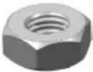 |
| B9 | Bolt | M8*16 | 20 | 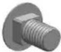 |
| B10 | Nut | M4 | 4 |  |
| B11 | Locking Washer | 4 | 4 |  |
| B12 | Washer | 4 | 4 |  |
| B13 | Screw | M4*12 | 4 |  |
| B14 | Switch | N/A | 1 |  |
| B15 | Cable | N/A | 1 |  |
| B16 | Cable Bushing | M16x1.5 | 1 | 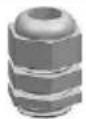 |
| B17 | Cable Ground | N/A | 1 | 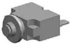 |
| B18 | Screw | ST2.9x9.5 | 12 |  |
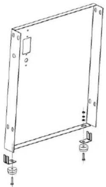
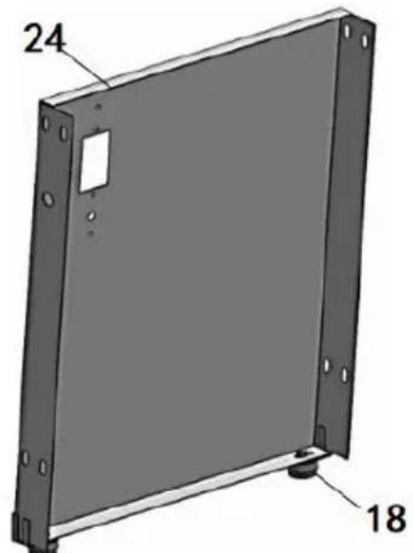
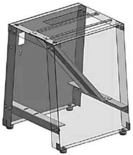
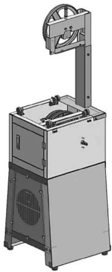
Step1
| Assembly of Motor box | |
| 1-1 | 1-2 |
 |  |
| 1-3 | 1-4 |
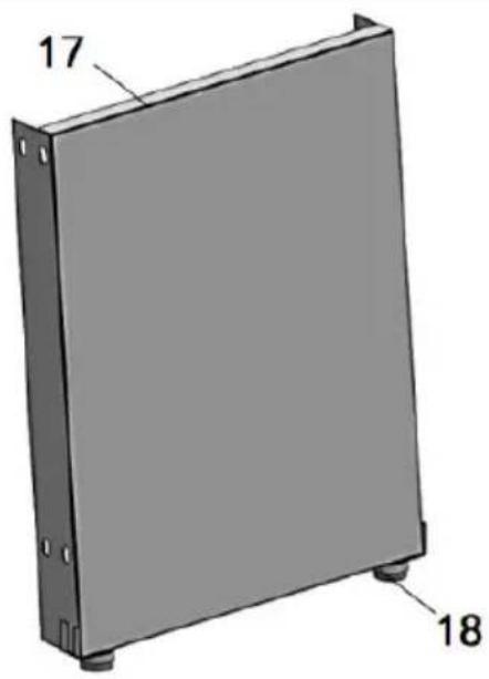 | 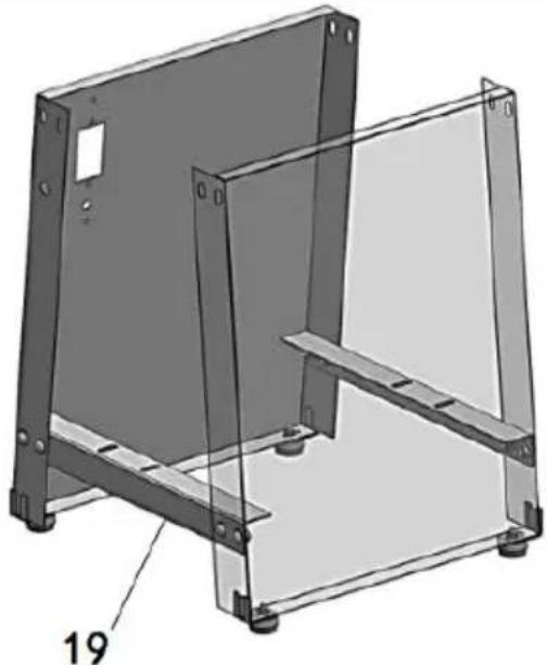 |
| 1-5 | 1-6 |
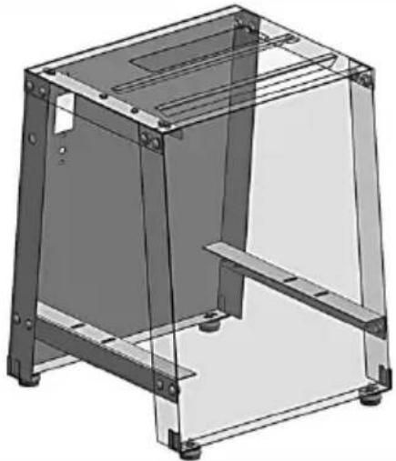 | 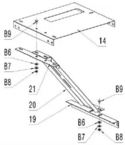 |
| 1-7 | 1-8 |
 |  |
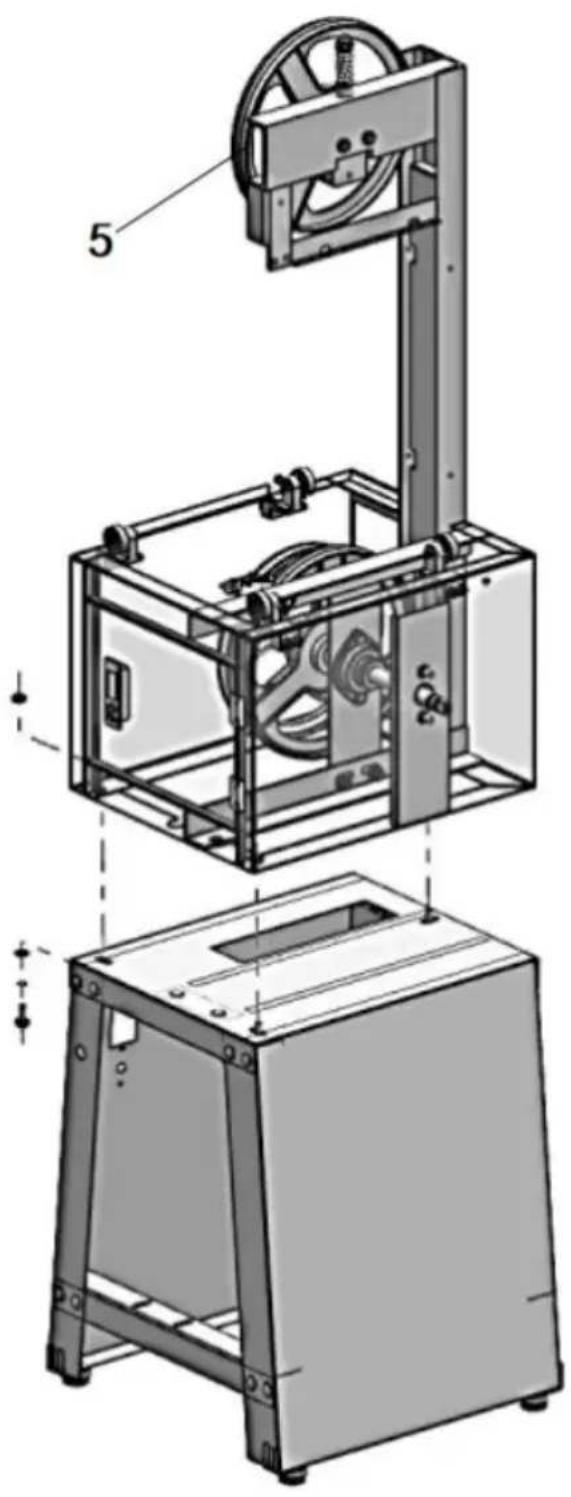
Step2
| Assembly of Transmission Case and Motor Case | |
| 2-1 | 2-2 |
 |  |
| 2-3 | |
 | |
Step3
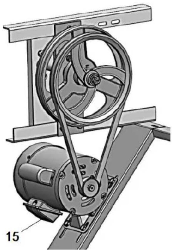
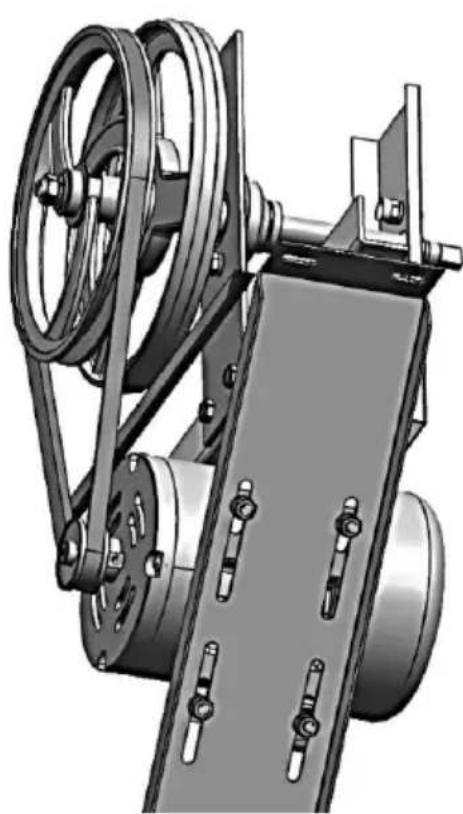
| Assembly of Triangle Belt | |
| 3-1 | 3-2 |
 |  |
| 3-3 | |
 | |
Step4
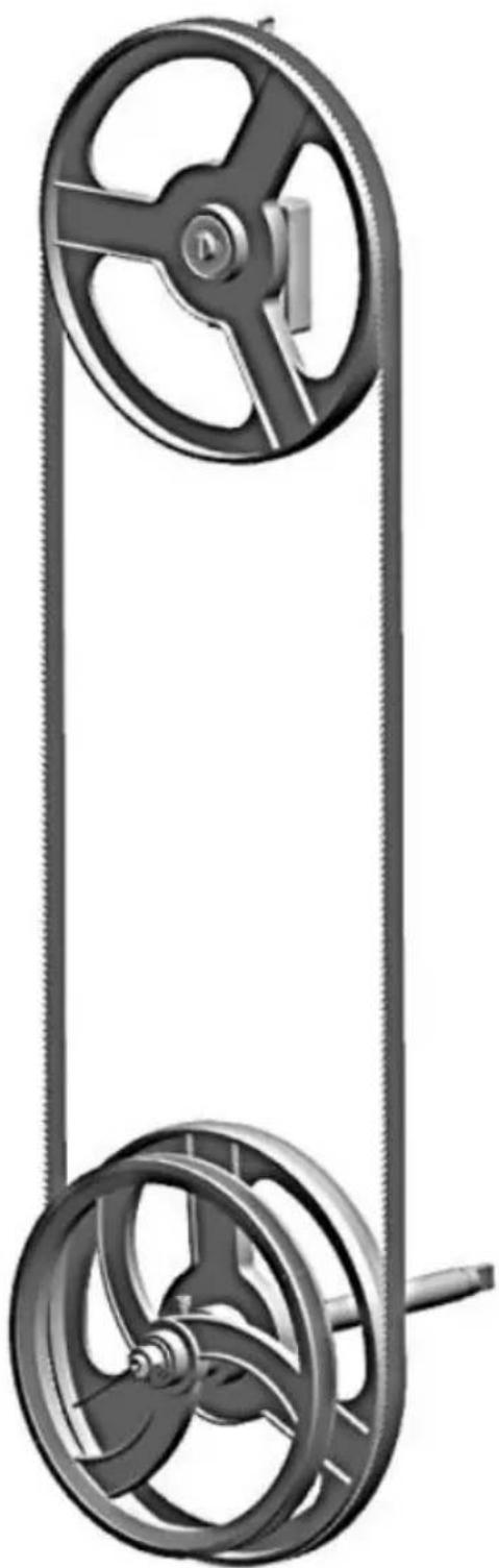
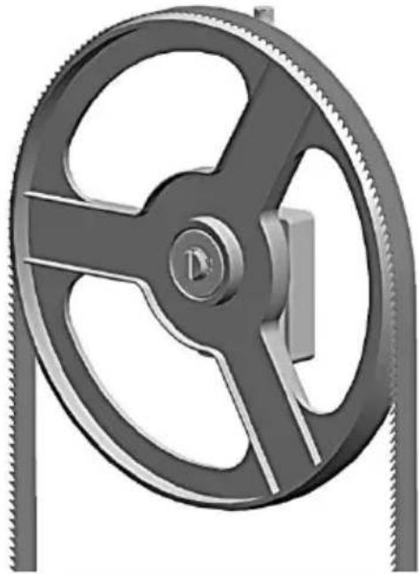
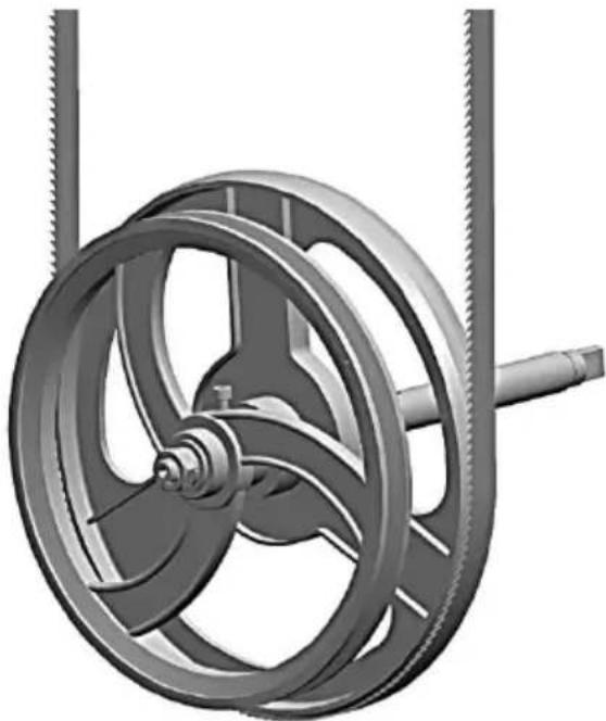
| Assembly of Saw Blade | |
| 4-1 | 4-2 |
 |  |
| 4-3 | |
 | |
Step5
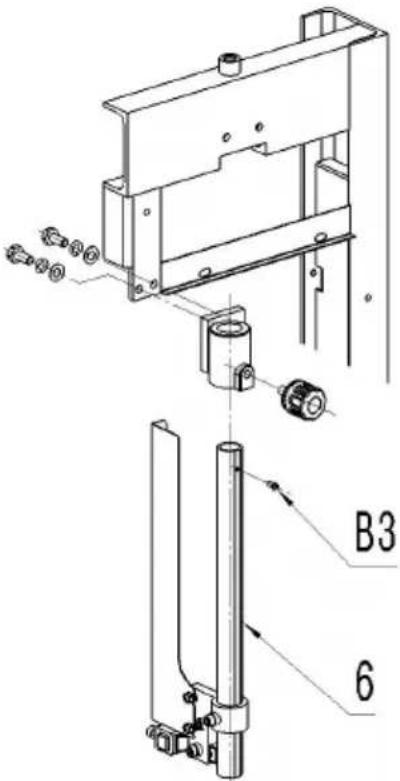
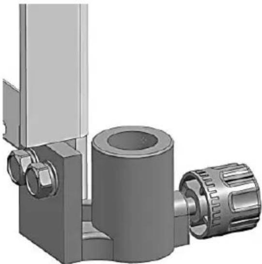
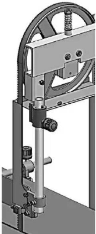
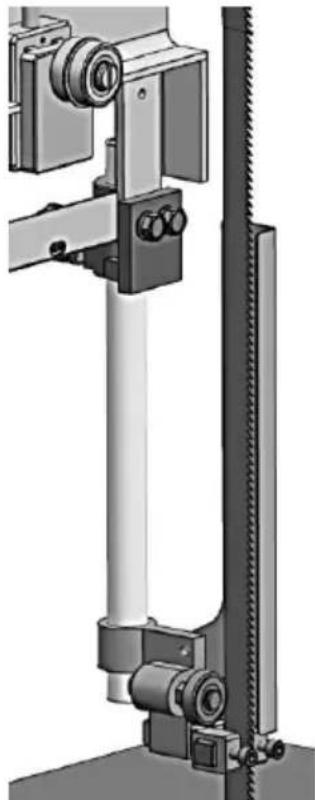
| Assembly of Fixing Device of Saw Blade | |
| 5-1 | 5-2 |
 |  |
| 5-3 | 5-4 |
 |  |
Step6
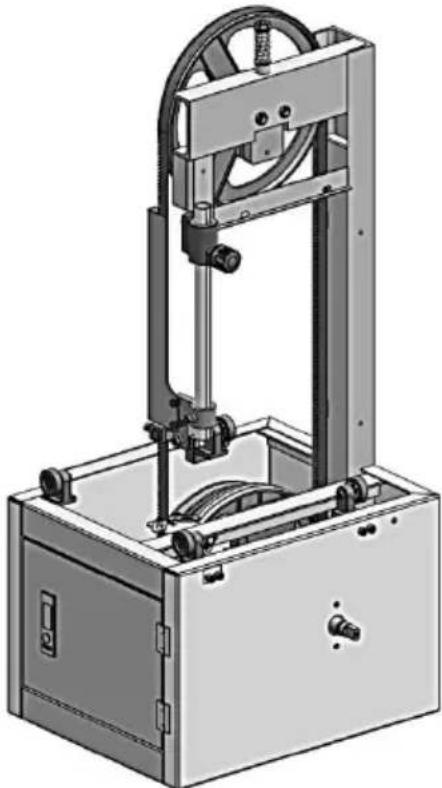
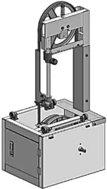
| Assembly of Bone Saw Machine's Cover | |
| 6-1 | 6-2 |
 |  |
| 6-3 | 6-4 |
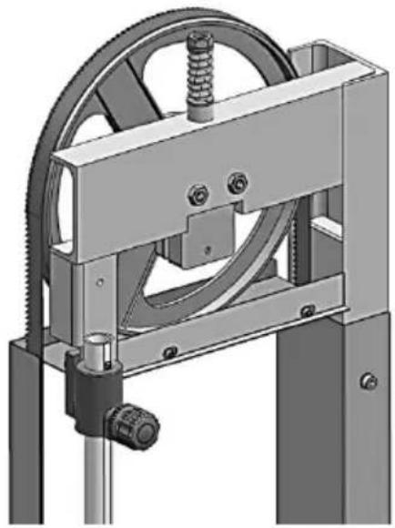 | 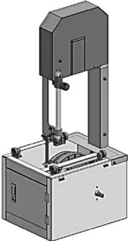 |
Step7
| Assembly of Table | |
| 7-1 | 7-2 |
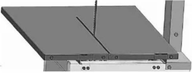 | 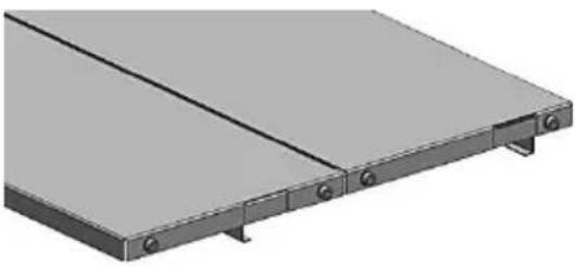 |
| 7-3 | 7-4 |
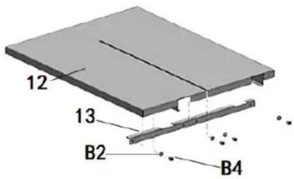 | 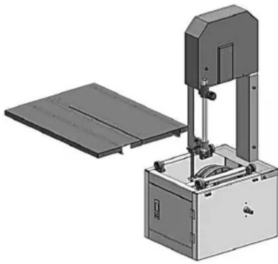 |
| 7-5 | 7-6 |
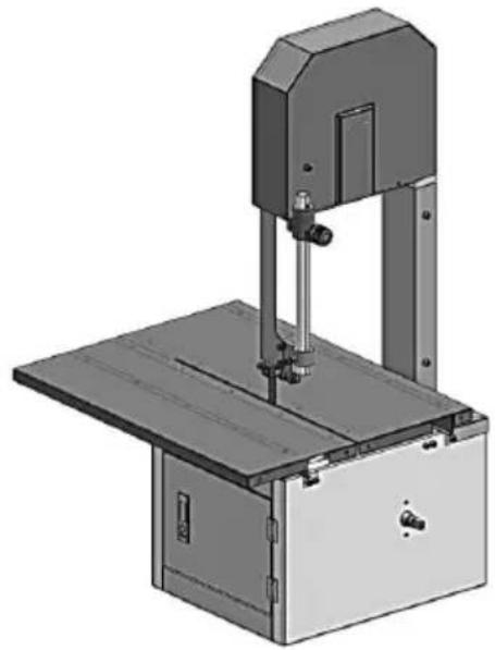 | 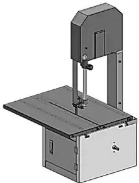 |
Step8
| Assembly of Plate Adjusting Mechanism | |
| 8-1 | 8-2 |
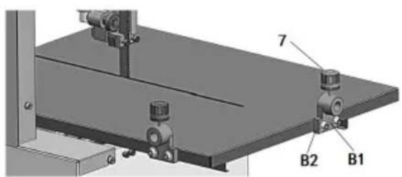 | 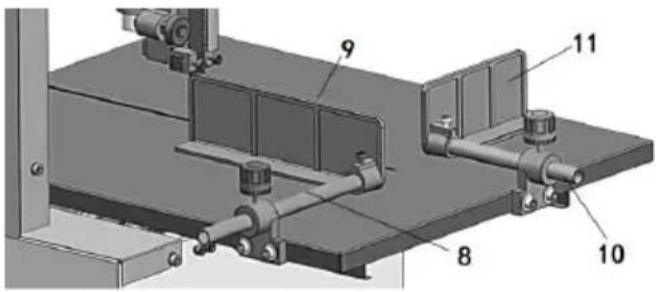 |
Step9
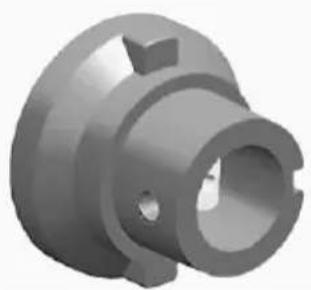
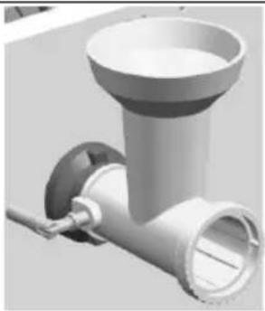
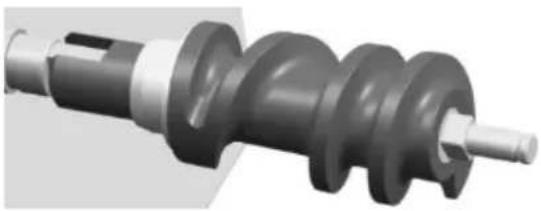
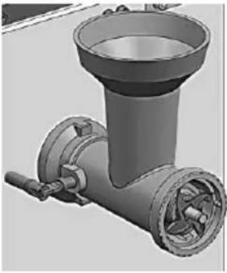
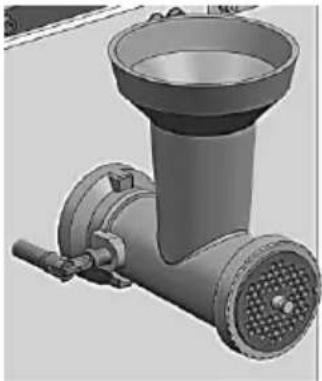
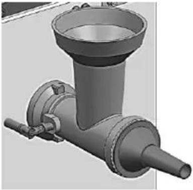
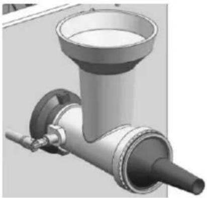
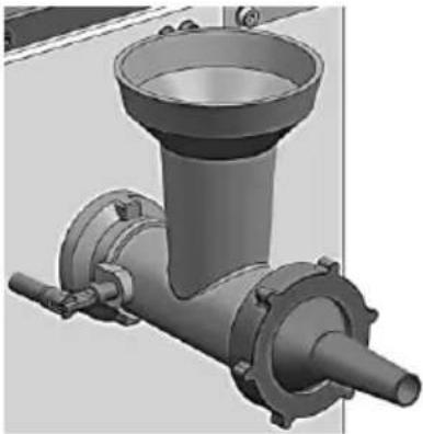
| Assembly of Meat Milling Mechanism | |
| 9-1 | 9-2 |
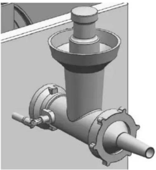 | 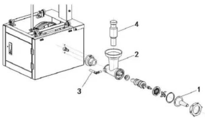 |
| 9-3 | 9-4 |
 |  |
| 9-5 | 9-6 |
 |  |
| 9-7 | 9-8 |
 |  |
| 9-9 | 9-10 |
 |  |
Step10
| Connection of Circuit |
| 10-1 |
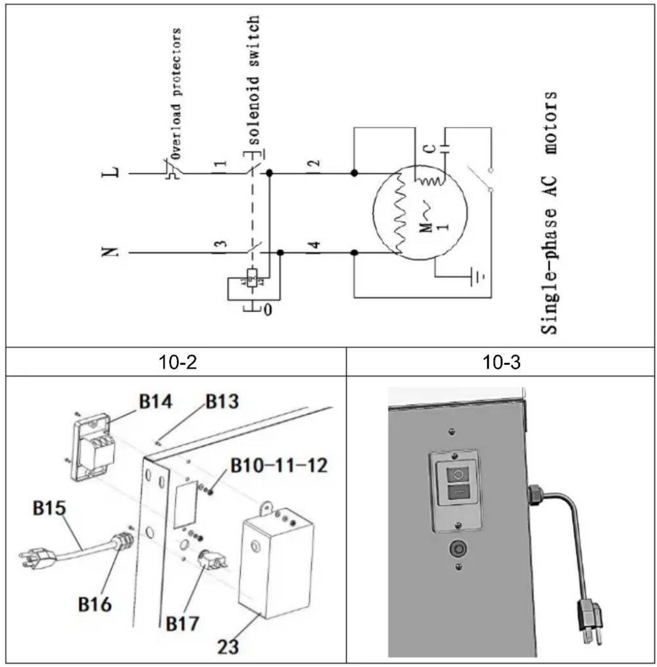
Step11
| Assembly of Motor Gear Plate |
| 11-1 |
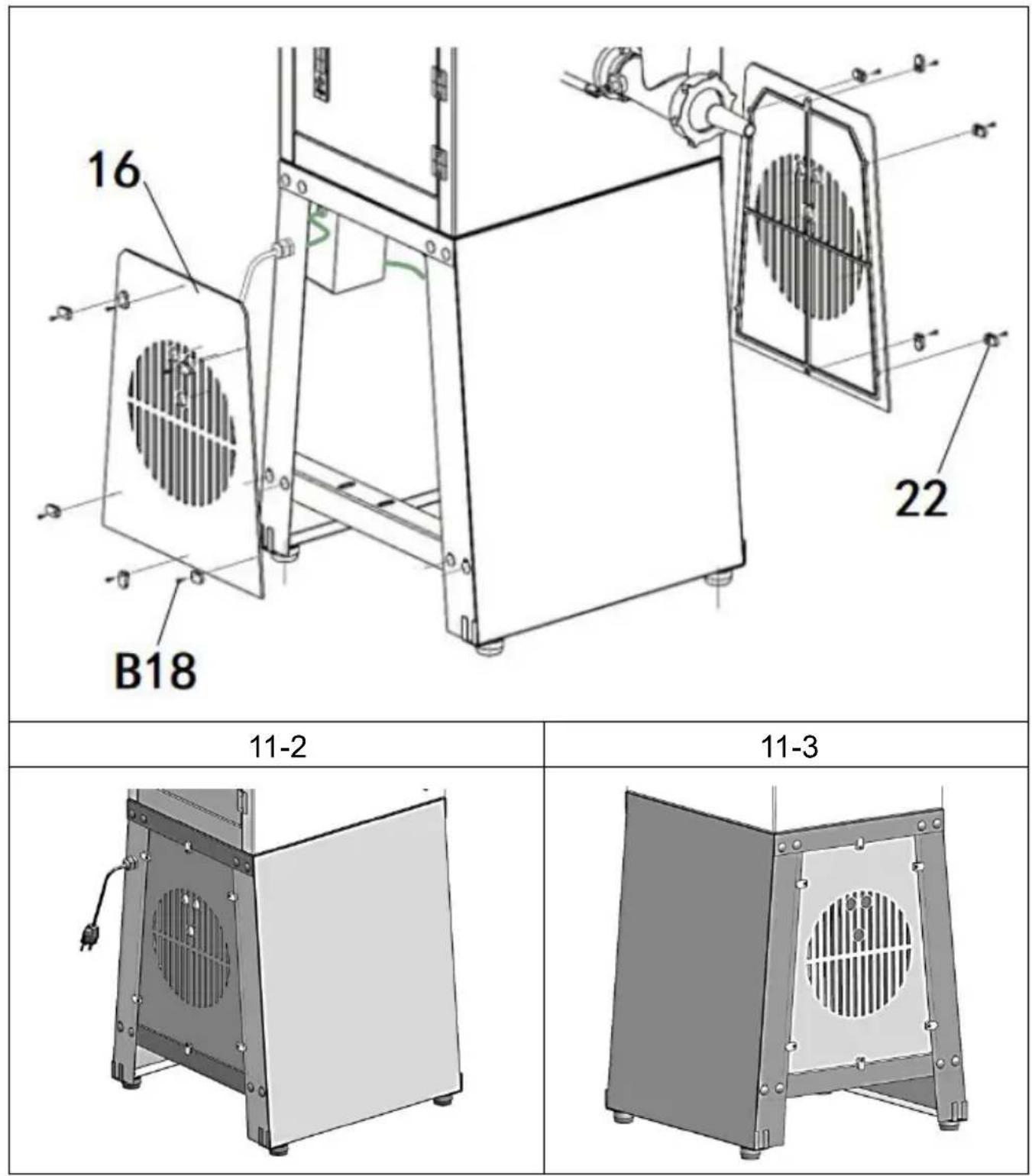
Step12
Explosive View
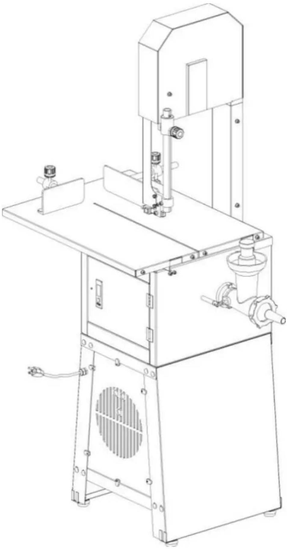
natural_image
Technical line drawing of a mechanical device with no visible text or symbols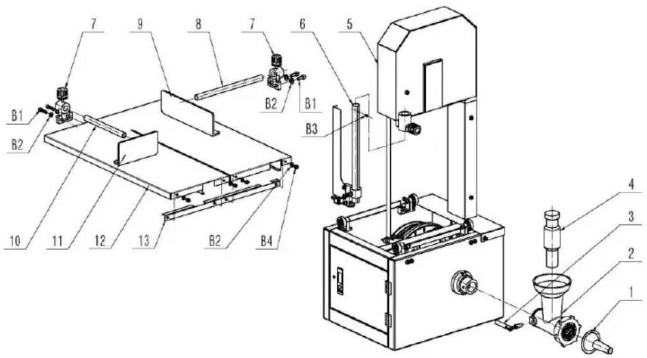
VEVOR®
TOUGH TOOLS, HALF PRICE
Technical Support and E-Warranty Certificate
www.vevor.com/support
VEVOR®
TOUGH TOOLS, HALF PRICE
natural_image
Technical line drawing of a mechanical device with no visible text or symbolsBESOIN D'AIDE ? CONTACTEZ-NOUS!
natural_image
Exterior view of a metallic door or cabinet with labeled points E and directional arrows indicating components (no text or symbols beyond labels)Figure 3
REMPLACEMENT OU RÉGLAGE DE LA LAME DE SCIE
natural_image
Mechanical device with a wheel and spring assembly, labeled A (no text or symbols on the device itself)Figure 4
TABLE DE TRAVAIL
natural_image
Exterior view of a mechanical device with a labeled component 'A' and a vertical control panel (no text or symbols on the device itself)Figure 7
CENTRAGE DE LA LAME SUR ROUE
ASSEMBLER LE HACHOIR À VIANDE
natural_image
Technical illustration of a manual cutting machine labeled Figure 13, showing internal components and assembly (no text or symbols on the machine itself)Figure 14
ASSEMBLER LA MACHINE SUR PLACE
natural_image
Close-up of a mechanical component with a black base and metallic bracket (no visible text or symbols)Figure 16
natural_image
Exterior view of a black rectangular electronic device with labeled points A and directional arrows (no text or symbols beyond labels)Figure 17
AJUSTEMENT DE LA COURROIE
natural_image
Exterior view of a mechanical component with a circular cutout and labeled point A (no text or symbols beyond label)Figure 20
INTERRUPTEUR DE DÉMARRAGE
natural_image
Close-up of a black electrical switch with two buttons and a vertical indicator (no text or symbols visible)Figure 21
Figure 24
natural_image
Mechanical assembly diagram showing a motor with force application points (no text or symbols)Figure 26
natural_image
Mechanical assembly diagram showing a valve mounted on a metal component with labeled point A (no text or symbols beyond label)Figure 27
natural_image
Industrial machine with metal components and control arms (no visible text or symbols)Figure 28
DÉMONTAGE DU HACHEUR À VIANDE
natural_image
Metal mechanical component with conical shaft and flange (no visible text or symbols)Figure 29
ENTRETIEN ET NETTOYAGE QUOTIDIEN
natural_image
Technical line drawing of a mechanical machine with no visible text or symbols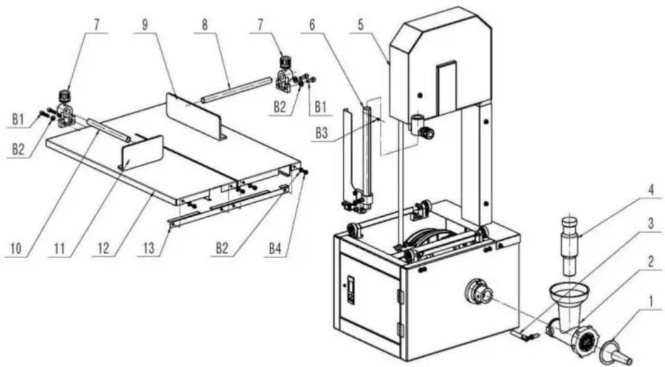
VEVOR®
TOUGH TOOLS, HALF PRICE
natural_image
Technical line drawing of a mechanical device with no visible text or symbolsnatural_image
Exterior view of a metallic door or cabinet with labeled points E and directional arrows indicating components (no text or symbols beyond labels)Figure 3
natural_image
Mechanical device with a wheel and spring assembly, labeled 'A' (no text or symbols on the device itself)Figure 4
ARBEITSTISCH
natural_image
Exterior view of a mechanical device with a labeled component 'A' and a scroll wheel (no text or symbols on the device itself)Figure 7
natural_image
Technical illustration of a manual cutting machine labeled Figure 13, showing internal components and assembly (no text or symbols on the machine itself)Figure 14
MASCHINE ZUM STAND MONTIEREN
natural_image
Close-up of a mechanical component with a black base and metallic bracket (no visible text or symbols)Figure 16
natural_image
Exterior view of a black rectangular electronic device with labeled points A and directional arrows (no text or symbols beyond labels)Figure 17
natural_image
Exterior view of a mechanical component with a circular cutout and labeled point A (no text or symbols beyond label)Figure 20
STARTSCHALTER
natural_image
Close-up of a black electrical switch with two buttons and a vertical indicator (no text or symbols visible)Figure 21
MONTAGE DES SCHALTERS Abb. 22A
Figure 24
natural_image
Mechanical assembly diagram showing a motor or conveyor system with labeled components (no readable text or symbols)Figure 26
natural_image
Mechanical assembly diagram showing a valve mounted on a metal component with labeled point A (no text or symbols beyond label)Figure 27
natural_image
Industrial machine with metal components and control arms (no visible text or symbols)Figure 28
DEMONTAGE DES FLEISCHWALZEN
natural_image
Metal mechanical component with conical shaft and flange (no visible text or symbols)Figure 29
natural_image
Technical line drawing of a mechanical machine with no visible text or symbols
VEVOR®
TOUGH TOOLS, HALF PRICE
www.vevor.com/support
VEVOR®
TOUGH TOOLS, HALF PRICE
natural_image
Technical line drawing of a mechanical device with no visible text or symbolsnatural_image
Exterior view of a metallic door or cabinet with two screws and an arrow pointing to the right side (no text or symbols visible)Figure 3
natural_image
Mechanical device with a wheel and spring assembly, labeled 'A' (no text or symbols on the device itself)Figure 4
TAVOLO DI LAVORO
MONTARE IL TRITATUTTO PER CARNE
natural_image
Technical illustration of a manual cutting machine labeled Figure 13, showing internal components and assembly (no text or symbols on the device itself)Figure 14
MONTARE LA MACCHINA SUL SUPPORTO
natural_image
Close-up of a mechanical component with a black base and metallic bracket (no visible text or symbols)Figure 16
natural_image
Exterior view of a black rectangular electronic device with labeled points A and directional arrows (no text or symbols beyond labels)Figure 17
REGOLARE LA CINGHIA V (I)
natural_image
Exterior view of a mechanical component with a circular cutout and labeled point A (no text or symbols beyond label)Figure 20
INTERRUTTORE DI AVVIO
natural_image
Close-up of a black electrical switch with two buttons and a vertical indicator (no text or symbols visible)Figure 21
Figure 24
natural_image
Mechanical assembly diagram showing a motor or conveyor system with labeled components (no readable text or symbols)Figure 26
natural_image
Mechanical assembly diagram showing a valve mounted on a metal component with labeled point A (no text or symbols beyond label)Figure 27
natural_image
Industrial machine with control panel and mechanical arms (no visible text or symbols)Figure 28
SMONTAGGIO DEL TRITATORE DI CARNE
natural_image
Metal mechanical component with conical shaft and flange (no visible text or symbols)Figure 29
natural_image
Technical line drawing of a mechanical machine with no visible text or symbols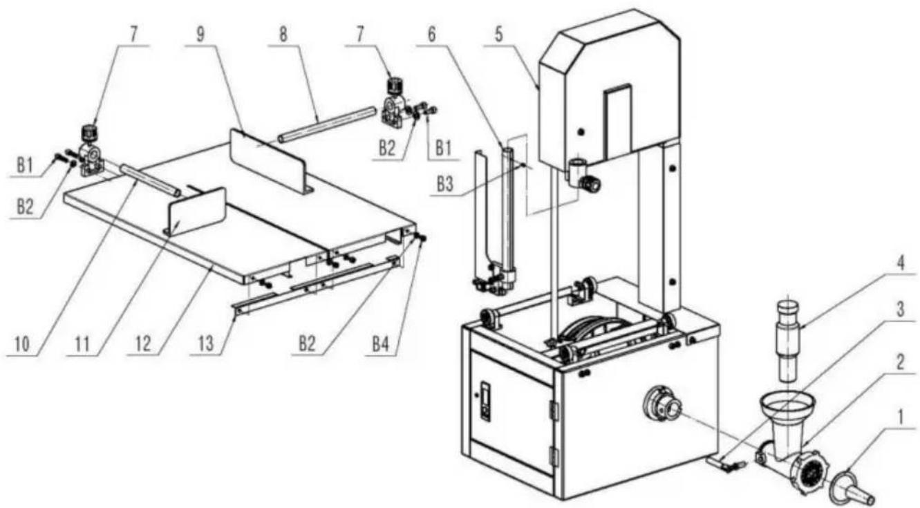
VEVOR®
TOUGH TOOLS, HALF PRICE
elettronica www.vevor.com/support
VEVOR®
TOUGH TOOLS, HALF PRICE
natural_image
Technical line drawing of a mechanical device with no visible text or symbolsnatural_image
Exterior view of a metallic door with two buttons and an arrow pointing to the right side (no text or symbols visible)Figure 3
REEMPLAZO O AJUSTE DE LA HOJA DE SIERRA
natural_image
Mechanical device with a wheel and spring assembly, labeled A (no text or symbols on the device itself)Figure 4
MESA DE TRABAJO
natural_image
Exterior view of a mechanical device with a labeled component 'A' and a vertical control panel (no text or symbols on the device itself)Figure 7
CENTRADO DE LA HOJA EN LA RUEDA
MONTAR LA PICADORA DE CARNE
1 Afloje la manija (Fig. 13A)
natural_image
Technical illustration of a manual cutting machine labeled Figure 13, showing internal components and assembly (no text or symbols on the machine itself)Figure 14
MONTAR LA MÁQUINA EN PIE
natural_image
Close-up of a mechanical component with a black base and metallic bracket (no visible text or symbols)Figure 16
natural_image
Exterior view of a black rectangular electronic device with labeled points A and directional arrows (no text or symbols beyond labels)Figure 17
AJUSTE V CORREA (I)
natural_image
Exterior view of a mechanical component with a circular cutout and labeled point A (no text or symbols beyond label)Figure 20
INTERRUPTOR DE ARRANQUE
natural_image
Close-up of a black electrical switch with two buttons and a circular indicator (no text or symbols visible)Figure 21
MONTAJE DEL INTERRUPTOR La Fig.
Figure 24
natural_image
Mechanical assembly diagram showing a motor with force application points (no text or symbols)Figure 26
natural_image
Mechanical assembly diagram showing a valve mounted on a metal component with labeled point A (no text or symbols beyond label)Figure 27
natural_image
Industrial machine with metal components and control arms (no visible text or symbols)Figure 28
DESMONTAJE PICADORA DE CARNE
natural_image
Mechanical component with conical shaft and flange (no visible text or symbols)Figure 29
MANTENIMIENTO Y LIMPIEZA DIARIA
natural_image
Technical line drawing of a mechanical machine with no visible text or symbols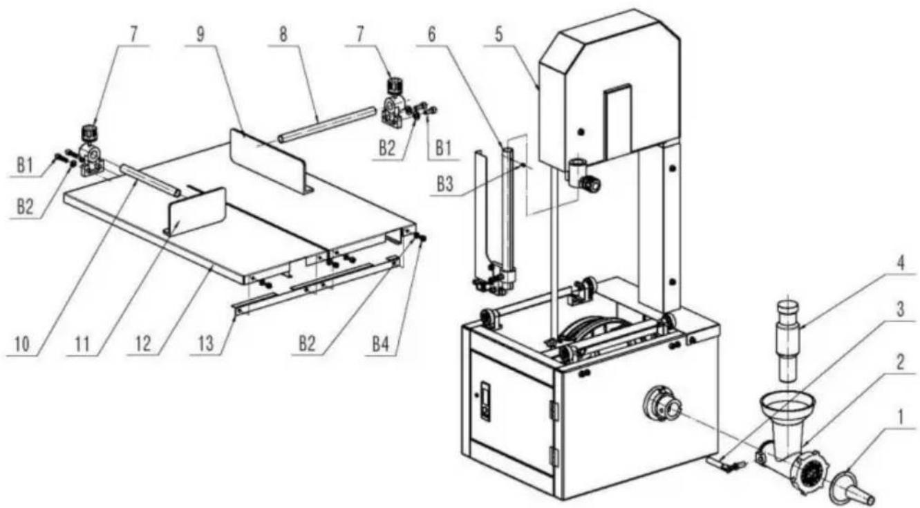
VEVOR®
TOUGH TOOLS, HALF PRICE
natural_image
Technical line drawing of a mechanical device with no visible text or symbolsPOTRZEBUJESZ POMOCY? SKONTAKTUJ SIĘ Z NAMI!
natural_image
Exterior view of a metallic door or cabinet with labeled points E and directional arrows indicating components (no text or symbols beyond labels)Figure 3
WYMIANA LUB REGULACJA PIŁY
natural_image
Mechanical device with a wheel and spring assembly, labeled 'A' (no text or symbols on the device itself)Figure 4
STÓŁ ROBOCZY
Aby usunąć stół.
natural_image
Exterior view of a mechanical device with a labeled component 'A' and an arrow pointing to a vertical panel (no text or symbols on the device itself)Figure 7
CENTROWANIE OSTRZY NA KOŁACH
ZAMONTUJ ROZDRABNIACZ DO MIĘSA
natural_image
Technical illustration of a manual cutting machine labeled Figure 13, showing internal components and assembly (no text or symbols on the machine itself)Figure 14
ZMONTOWAĆ MASZYNĘ DO STOIENIA
natural_image
Close-up of a mechanical component with a black base and metallic bracket (no visible text or symbols)Figure 16
natural_image
Exterior view of a black rectangular electronic device with labeled points A and directional arrows (no text or symbols beyond labels)Figure 17
REGULACJA PASKU
natural_image
Exterior view of a mechanical component with a circular cutout and labeled point A (no text or symbols beyond label)Figure 20
natural_image
Close-up of a black electrical switch with two buttons and a vertical indicator (no text or symbols visible)Figure 21
Figure 24
natural_image
Mechanical assembly diagram showing a motor or conveyor system with labeled components (no readable text or symbols)Figure 26
natural_image
Mechanical assembly diagram showing a valve mounted on a metal component with labeled point A (no text or symbols beyond label)Figure 27
natural_image
Industrial machine with metal components and control arms (no visible text or symbols)Figure 28
DEMONTAŻ ROZDRABNIACZA DO MIĘSA
natural_image
Metal mechanical component with conical shaft and flange (no visible text or symbols)Figure 29
KONSERWACJA I CODZIENNE CZYSZCZENIE
natural_image
Technical line drawing of a mechanical machine with no visible text or symbols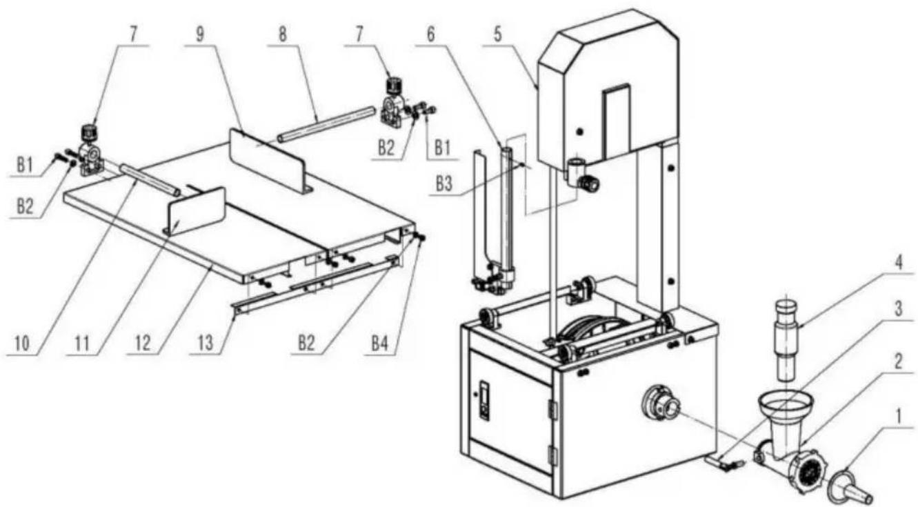
VEVOR®
TOUGH TOOLS, HALF PRICE
www.vevor.com/support
VEVOR®
TOUGH TOOLS, HALF PRICE
Technische ondersteuning en e-garantiecertificaat www.vevor.com/support
BEENZAAGMACHINE
MODEL: JG-250
natural_image
Technical line drawing of a mechanical device with no visible text or symbolsHULP NODIG? NEEM CONTACT MET ONS OP!
natural_image
Exterior view of a metallic door with labeled component E (no text or symbols beyond label)Figure 3
ZAAGBLAD VERVANGEN OF AANPASSEN
natural_image
Mechanical device with a wheel and spring assembly, labeled 'A' (no text or symbols on the device itself)Figure 4
WERKTAFEL
natural_image
Exterior view of a mechanical device with a labeled component 'A' and a scroll wheel (no text or symbols on the device itself)Figure 7
MONTEER DE VLEESHAKPER
natural_image
Technical illustration of a manual cutting machine labeled Figure 13, showing internal components and assembly (no text or symbols on the machine itself)Figure 14
MONTEER DE MACHINE OP DE STAAT
natural_image
Close-up of a mechanical component with a black base and metallic bracket (no visible text or symbols)Figure 16
natural_image
Exterior view of a black rectangular electronic device with labeled points A and directional arrows (no text or symbols beyond labels)Figure 17
VRIEM AANPASSEN
natural_image
Exterior view of a mechanical component with a circular cutout and labeled point A (no text or symbols beyond label)Figure 20
STARTSCHAKELAAR
natural_image
Close-up of a black electrical switch with two buttons and a vertical indicator (no text or symbols visible)Figure 21
MONTEREN VAN DE SCHAKELAAR
Figure 24
natural_image
Mechanical assembly diagram showing a motor or conveyor system with labeled components (no readable text or symbols)Figure 26
natural_image
Mechanical assembly diagram showing a valve mounted on a metal component, labeled 'A' (no text or symbols beyond label)Figure 27
natural_image
Industrial machine with metal components and control arms (no visible text or symbols)Figure 28
DEMONTAGE VAN DE VLEESHAKPER
natural_image
Metal mechanical component with conical shaft and flange (no visible text or symbols)Figure 29
ONDERHOUD EN DAGELIJKSE REINIGING
natural_image
Technical line drawing of a mechanical machine with no visible text or symbols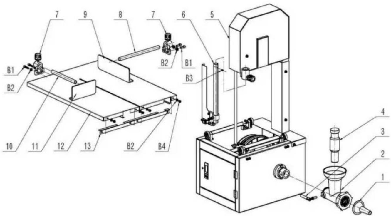
VEVOR®
TOUGH TOOLS, HALF PRICE
garantiecertificaat www.vevor.com/support
VEVOR®
TOUGH TOOLS, HALF PRICE
natural_image
Technical line drawing of a mechanical device with no visible text or symbolsBEHÖVER HJÄLP? KONTAKTA OSS!
natural_image
Exterior view of a metallic door or cabinet with labeled points E and directional arrows indicating components (no text or symbols beyond labels)Figure 3
BYTA ELLER JUSTERA SÅGBLAD
natural_image
Mechanical device with a wheel and spring assembly, labeled 'A' (no text or symbols on the device itself)Figure 4
ARBETSBORD
natural_image
Exterior view of a mechanical device with a labeled component 'A' and a vertical lock mechanism (no text or symbols beyond label)Figure 7
BLAD CENTRERA PÅ HJUL
SÄTTA SAMMAN KÖTTHACKAREN
natural_image
Technical illustration of a manual cutting machine labeled Figure 13, showing internal components and assembly (no text or symbols on the machine itself)Figure 14
MONTERA MASKINEN FÖR ATT STÅ
natural_image
Close-up of a mechanical component with a black base and metallic bracket (no visible text or symbols)Figure 16
natural_image
Exterior view of a black rectangular electronic device with labeled points A and directional arrows (no text or symbols beyond labels)Figure 17
JUSTERA KILREM
natural_image
Exterior view of a mechanical component with a circular cutout and labeled point A (no text or symbols beyond label)Figure 20
START SWITCH
natural_image
Close-up of a black electrical switch with two buttons and a vertical indicator (no text or symbols visible)Figure 21
MONTERING AV BRYTARE Fig 22A
Figure 24
natural_image
Mechanical assembly diagram showing a motor or conveyor system with labeled components (no readable text or symbols)Figure 26
natural_image
Mechanical assembly diagram showing a valve mounted on a metal component with labeled point A (no text or symbols beyond label)Figure 27
natural_image
Industrial machine with control panel and mechanical arms (no visible text or symbols)Figure 28
DEMONTERING AV KÖTTHACKARE
Figur 29 visar kötthackaren
natural_image
Metal mechanical component with conical shaft and flange (no visible text or symbols)Figure 29
UNDERHÅLL OCH DAGLIG RENGÖRING
natural_image
Technical line drawing of a mechanical machine with no visible text or symbols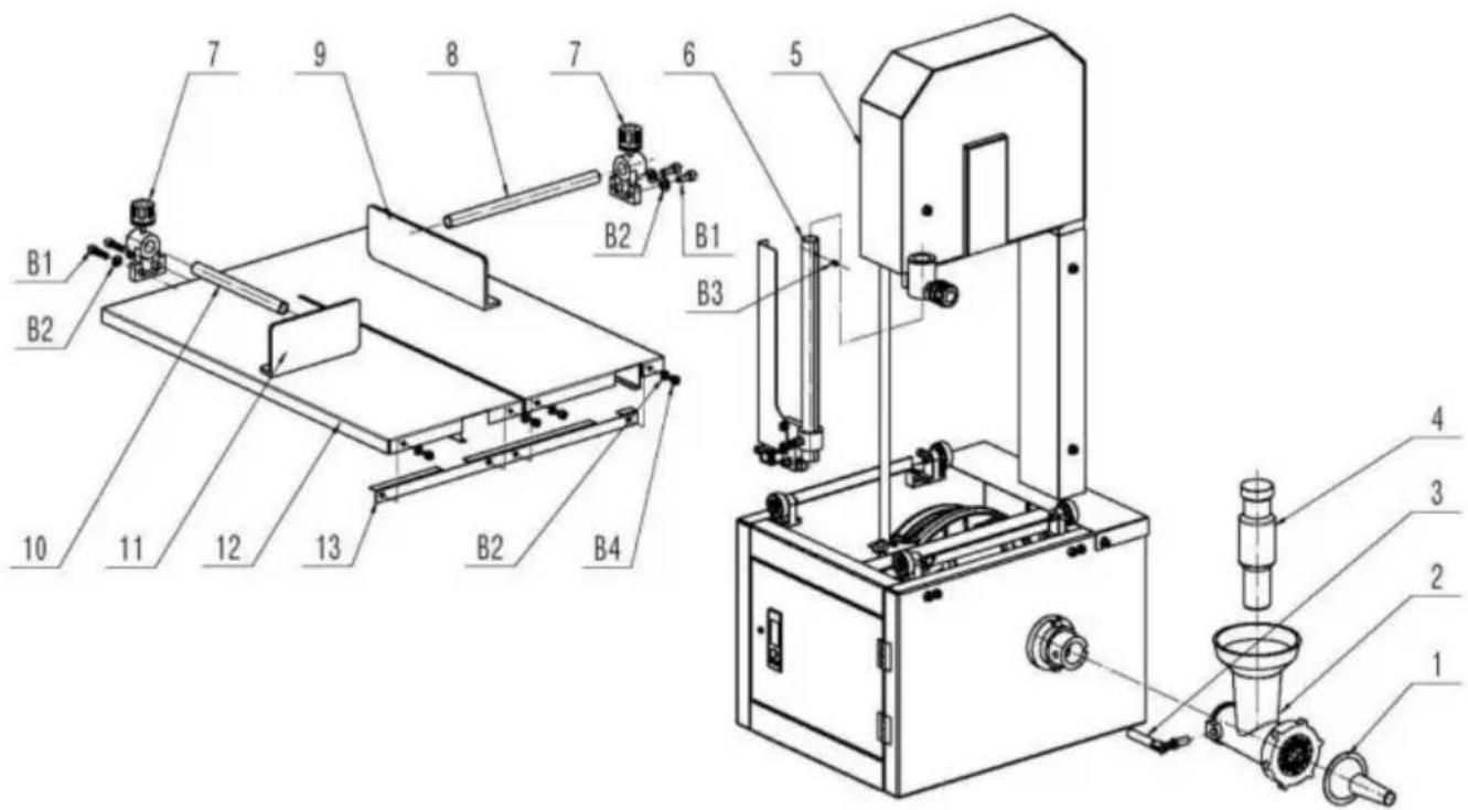
VEVOR®
TOUGH TOOLS, HALF PRICE
www.vevor.com/support
- BONE SAW MACHINE
- VEVOR®
- NEED HELP? CONTACT US!
- IMPORTANT SAFEGUARDS
- WARNING:
- SAVE THESE INSTRUCTIONS
- Cleaning
- SAW BLADE GUARD COVER
- REMOVING THE GUARD COVER
- REPLACING OR ADJUSTING SAW BLADE
- WORKING TABLE
- PUSH BUTTON
- BLADE CENTERING ON WHEEL
- UPPER BLADE FIXED SEAT
- After blade is vertically adjusted.
- Tighten the screw(Fig 9A)
- LOWER BLADE FIXED SEA
- ASSEMBLE THE MEAT CHOPPER
- ASSEMBLE MACHINE TO STAND
- ADJUST VBELT
- (II)Adjusting V-Belt vertical
- START SWITCH
- ASSEMBLING THE SWITCH
- ASSEMBLY OF GUIDE WHEES ANDTABLE
- ASSEMBLY OF FENCE AND PUSHER
- DISASSEMBLY OF MEAT CHOPPER
- MAINTENANCE & DAILY CLEANING
- Parts List
- Step8
- Step9
- Step12
- TOUGH TOOLS, HALF PRICE
- BESOIN D'AIDE ? CONTACTEZ-NOUS!
- REMPLACEMENT OU RÉGLAGE DE LA LAME DE SCIE
- TABLE DE TRAVAIL
- CENTRAGE DE LA LAME SUR ROUE
- ASSEMBLER LE HACHOIR À VIANDE
- ASSEMBLER LA MACHINE SUR PLACE
- AJUSTEMENT DE LA COURROIE
- ENTRETIEN ET NETTOYAGE QUOTIDIEN
- ARBEITSTISCH
- MASCHINE ZUM STAND MONTIEREN
- STARTSCHALTER
- MONTAGE DES SCHALTERS Abb. 22A
- DEMONTAGE DES FLEISCHWALZEN
- TAVOLO DI LAVORO
- MONTARE IL TRITATUTTO PER CARNE
- MONTARE LA MACCHINA SUL SUPPORTO
- REGOLARE LA CINGHIA V (I)
- INTERRUTTORE DI AVVIO
- SMONTAGGIO DEL TRITATORE DI CARNE
- REEMPLAZO O AJUSTE DE LA HOJA DE SIERRA
- MESA DE TRABAJO
- CENTRADO DE LA HOJA EN LA RUEDA
- MONTAR LA PICADORA DE CARNE
- MONTAR LA MÁQUINA EN PIE
- AJUSTE V CORREA (I)
- DESMONTAJE PICADORA DE CARNE
- MANTENIMIENTO Y LIMPIEZA DIARIA
- WYMIANA LUB REGULACJA PIŁY
- STÓŁ ROBOCZY
- CENTROWANIE OSTRZY NA KOŁACH
- ZAMONTUJ ROZDRABNIACZ DO MIĘSA
- ZMONTOWAĆ MASZYNĘ DO STOIENIA
- REGULACJA PASKU
- KONSERWACJA I CODZIENNE CZYSZCZENIE
- BEENZAAGMACHINE
- HULP NODIG? NEEM CONTACT MET ONS OP!
- ZAAGBLAD VERVANGEN OF AANPASSEN
- WERKTAFEL
- MONTEER DE VLEESHAKPER
- MONTEER DE MACHINE OP DE STAAT
- VRIEM AANPASSEN
- STARTSCHAKELAAR
- MONTEREN VAN DE SCHAKELAAR
- DEMONTAGE VAN DE VLEESHAKPER
- ONDERHOUD EN DAGELIJKSE REINIGING
- BEHÖVER HJÄLP? KONTAKTA OSS!
- BYTA ELLER JUSTERA SÅGBLAD
- ARBETSBORD
- BLAD CENTRERA PÅ HJUL
- SÄTTA SAMMAN KÖTTHACKAREN
- MONTERA MASKINEN FÖR ATT STÅ
- JUSTERA KILREM
- MONTERING AV BRYTARE Fig 22A
- DEMONTERING AV KÖTTHACKARE
- UNDERHÅLL OCH DAGLIG RENGÖRING
Brand : Vevor
Model : JG-250
Category : Saw