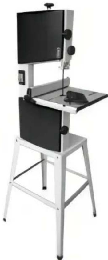
HBS250 - Saw Vevor - Free user manual and instructions
Find the device manual for free HBS250 Vevor in PDF.

| Product type | Band saw |
| Brand | Vevor |
| Model | HBS250 |
| Motor power | 370 W |
| Power supply | 230 V ~ 50/60 Hz (estimation) |
| Max. throat width | 245 mm |
| Max. cutting height | 160 mm |
| Blade length | 1832 mm |
| Table dimensions | 340 x 335 mm |
| Blade speed (50 Hz) | 730 m/min |
| Blade speed (60 Hz) | 890 m/min |
| Net weight | 28.8 kg |
| Gross weight | 32 kg |
| Table tilt | 0° to 45° (bevel) |
| Miter gauge | Rotation 60° on each side, stops at 45° and 90° |
| Safety devices | Upper and lower blade guards, emergency stop, microswitches, push stick |
| Included accessories | Parallel guide, miter gauge, push stick, wrenches, push stick holder, legs and cross braces for stand |
| Dust extraction connection | Dust extraction port |
| Maintenance | Regular cleaning of chips, checking blade tension, replacing blade and wheel tires |
| Repairability | Spare parts available, repair by a qualified electrician |
| Warranty | Electronic warranty certificate via www.vevor.com/support |
Frequently Asked Questions - HBS250 Vevor
User questions about HBS250 Vevor
0 question about this device. Answer the ones you know or ask your own.
Ask a new question about this device
Download the instructions for your Saw in PDF format for free! Find your manual HBS250 - Vevor and take your electronic device back in hand. On this page are published all the documents necessary for the use of your device. HBS250 by Vevor.
USER MANUAL HBS250 Vevor
Technical Support and E-Warranty Certificate www.vevor.com/support
BAND SAWR USER MANUAL
MODEL:HBS250
We continue to be committed to provide you tools with competitive price. "Save Half", "Half Price" or any other similar expressions used by us only represents an estimate of savings you might benefit from buying certain tools with us compared to the major top brands and does not necessarily mean to cover all categories of tools offered by us. You are kindly reminded to verify carefully when you are placing an order with us if you are actually saving half in comparison with the top major brands.
MODEL:HBS250
natural_image
Exterior view of a modern office building (no signage)NEED HELP? CONTACT US!
Have product questions? Need technical support? Please feel free contact us:
Technical Support and E-Warranty Certificate www.vevor.com/support
This is the original instruction, please read all manual instructions carefully before operating. VEVOR reserves a clear interpretation of user manual. The appearance of the product shall be subject to the product you received. Please forgive us that we won't inform you there are any technology or software updates on our product.
TABLE OF CONTENTS
Please Read First!....2
Safety 4
Transport....12
Machine Details....13
Initial Operation.... 19
Operation.... 21
Care And Maintenance....25
Repairs 29
Environmental Protection....29
Troubleshooting Guide....30
Technical Specifications....31
Electric Wiring Diagram....32
Exploded View and Part .List....33
PLEASE READ FIRST!
These operating instructions have been written to make it easier for you, the user, to learn how to operate this machine and to do so safely. The instructions should be used as follows:
- Read these instructions before use. Pay special attention to the safety information.
-
These operating instructions are intended for people with basic technical knowledge regarding the operation of a machine like this or similar electrical power tools. Inexperienced persons are strongly advised to seek competent advice and guidance from an experienced person before operating this machine.
-
Keep all documents supplied with this machine for future reference.
- This machine must not be sold or lent to someone else without being accompanied by all machine documents supplied with it.
- The manufacturer assumes no liability for any damage caused by neglect of these operating instructions.
Information in these instructions is marked as under:
 | Warning - To reduce the risk of injury, user must read instructions manual carefully. |
| ~ | Alternating current |
 | This symbol, placed before a safety comment, indicates a kind of precaution, warning, or danger. Ignoring this warning may lead to an accident. To reduce the risk of injury, fire, or electrocution, please always follow the recommendation shown below. |
 | Danger!Risk of personal injury or environmental damage! Risk of electric shock! Risk of personal injury by electric shock! |
 | Entanglement hazard! Risk of personal injury by body parts or clothin being drawn into the rotating saw blade. |
 | Caution! Risk of material damage. |
 | Note:Additional information. |
 | Warning- Be sure to wear ear protectors when using this product. |
 | Warning- Be sure to wear eye protectors when using this product. |
 | Warning- Be sure to wear gloves when using this product. |
 | Disposal information: This product is subject to the provision of European Directive 2012/ 19/EC. The symbol showing a wheelie bin crossed through indicates that the product requires separate refuse collection in the European Union. This applies to the product and all accessories marked with this symbol. Products marked as such may not be discarded with normal domestic waste, but must be taken to collection point for recycling electrical and electronic devices |
SAFETY

WARNING : Read all safety warnings,instructions,illustrations and specifications provided with this band saw.Failure to follow all instructions listed below may result in electric shock, fire and/or serious injury.
Save all warnings and instructions for future reference.

General Power Tool Safety Warnings-Work Area Safety
- Keep work area clean and well-lit. Cluttered or dark areas invite accidents.
- Do not operate power tools in explosive atmospheres, such as in the presence of flammable liquids, gases or dust. Power tools create sparks that may ignite dust or fumes.
- Keep children and bystanders away while operating a power tool. Distractions can cause you to lose control.

General Power Tool Safety Warnings-Electrical Safety
- Power tool plugs must match the outlet. Never modify the plug in any Do not use any adapter plugs with earthed(grounded)power
tools.Unmodified plugs and matching outlets will reduce risk of electric shock.
- Avoid body contact with earthed or grounded surfaces, such as pipes, radiators, ranges and refrigerators. There is an increased risk of electr shock if your body is earthed or grounded.
- Do not expose power tools to rain or wet conditions. Water entering a power tool will increase the risk of electric shock.
- Do not abuse the cord. Never use the cord for carrying, pulling or unplugging the power tool. Keep cord away from heat, oil, sharp edges moving parts. Damaged or entangled cords increase the risk of electric shock.
- When operating a power tool outdoors, use an extension cord suitable for outdoor use. Use of a cord suitable for outdoor use reduces the risk of electric shock.
- If operating a power tool in a damp location is unavoidable, use a residual current device(RCD)protected supply. Use of an RCD reduces the risk of electric shock.

General Power Tool Safety Warnings-Personal Safety
- Stay alert, watch what you are doing and use common sense when operating a power tool. Do not use a power tool while you are tired under the influence of drugs, alcohol or medication. A moment of inattention while operating power tools may result in serious personal injury.
- Use personal protective equipment. Always wear eye protection. Protective equipment such as a dust mask, non-skid safety shoes, hard hat or hearing protection used for appropriate conditions will reduce personal injuries.
- Prevent unintentional starting. Ensure the switch is in the off-position before connecting to power source and/or battery pack, picking up or carrying the tool. Carrying power tools with your finger on the switch are energizing power tools that have the switch on invites accidents.
- Remove any adjusting key or wrench before turning the power tool on wrench or a key left attached to a rotating part of the power tool may result in personal injury.
- Do not overreach. Keep proper footing and balance at all times. This enables better control of the power tool in unexpected situations.
- Dress properly.Do not wear loose clothing or jewellery.Keep your hair and clothing away from moving parts.Loose clothes,jewellery or long hair can be caught in moving parts.
- If devices are provided for the connection of dust extraction and collection facilities, ensure these are connected and properly used. Use of dust collection can reduce dust-related hazards.
- Do not let familiarity gained from frequent use of tools allow you to become complacent and ignore tool safety principles. A careless action can cause severe injury within a fraction of a second.
Power Tool Use and Care
- a) Do not force the power tool. Use the correct power tool for your application. The correct power tool will do the job better and safer at rate for which it was designed.
- Do not use the power tool if the switch does not turn on and off. An power tool that cannot be controlled with the switch is dangerous and must be repaired.
- Disconnect the plug from the power source and/or remove the battery pack, if detachable, from the power tool before making any adjustments, changing accessories, or storing power tools. Such preventive safety measures reduce the risk of starting the power tool accidentally.
- Store idle power tools out of the reach of children and do not allow persons unfamiliar with the power tool or these instructions to operate the power tool. Power tools are dangerous in the hands of untrained users.
- Maintain power tools and accessories.Check for misalignment or binding of moving parts,breakage of parts and any other condition that may affect the power tools operation.If damaged,have the power tool repaired before use.Many accidents are caused by poorly maintained power tools.
- Keep cutting tools sharp and clean. Properly maintained cutting tools with sharp cutting edges are less likely to bind and are easier to con
- Use the power tool, accessories and tool bits etc. in accordance with these instructions, taking into account the working conditions and the work to be performed. Use of the power tool for operations different from those intended could result in a hazardous situation.
- Keep handles and grasping surfaces dry, clean and free from oil and grease. Slippery handles and grasping surfaces do not allow for safe handling and control of the tool in unexpected situations.
Service
- Have your power tool serviced by a qualified repair person using only identical replacement parts. This will ensure that the safety of the power tool is maintained.
1. Specified Conditions of Use
- The machine is suitable for cutting wood,wood-derived materials and plastics.Do not cut round stock transverse to its longitudinal axis with suitable jigs or fixtures.The rotating saw blade could turn the workpiece.When sawing thin stock lay on edge,a suitable guide must be used for firm support.
- Any other use is not as specified. The manufacturer is not liable for any damage caused by unspecified use.
- Alteration of the machine or use of parts not approved by the equipment manufacturer can cause unforeseeable damage!
2. General Safety Information
- When using this tool observe the following safety instructions, to exclude the risk of personal injury or material damage. Please also observe the special safety instructions in the respective chapters.
- Where applicable, follow the legal directives or regulations for the prevention of accidents pertaining to the use of band saws.

General hazards!
- Keep your work area tidy-a messy work area invites accidents.
- Be alert.Know what you are doing.Set out to work with reason.Do not operate tool while under the influence of drugs,alcohol or
medication. Consider environmental conditions: keep work area well-lighted.
- Prevent adverse body positions.Ensure firm footing and keep your balance at all times.When working long stock use suitable supports. Do not operate tool near inflammable liquids or gases.
- The saw shall only be started and operated by persons familiar with band saws and who are at any time aware of the dangers associated with the operation of such tool.
- Keep bystanders, particularly children, out of the danger zone. Persons under 18 years of age shall use this tool only in the course of their vocational training, under the supervision of an instructor.
- Do not permit other persons to touch the tool or power cable while it is running.
- Do not overload tool "C use it only within the performance range it was designed for(see"Technical specifications").

Danger!Risk of Electric Shock!
- Do not expose tool to rain.
- Do not operate tool in damp or wet environment.
● Prevent body contact with earthed objects such as radiators, pipes, cooking stoves, refrigerators when operating this tool.
- Do not use the power cable for any purpose it is not intended for.

Risk of personal injury and crushing by moving parts!
- Do not operate the tool without installed guards.
● Always keep a sufficient distance from the band saw blade. Use suitable feeding aids if necessary.
- Keep sufficient distance to drive components when operating this tool. Do not attempt to stop the band saw blade by pushing the workpiece against its side.
- Ensure tool is disconnected from power supply before servicing. Ensure that when switching on(e.g.after servicing)no tools or loose parts are left on or in the tool.
● Turn power off if the tool is not used.

Cutting hazard, even with the cutting tool at a standstill!
Wear gloves when changing cutting tools.

Risk of kickback(workpiece is caught by the band saw blade
and thrown against the operator)!
- Do not jam workpieces.
- Cut thin or thin-walled workpieces only with fine-toothed saw blades. Always use sharp band saw blades.
- If in doubt, check workpiece for inclusion of foreign matter(e.g. nails or screws).
- Cut only stock of dimensions that allow for safe and secure holding which cutting. Never cut several workpieces at the same time and also no bundles containing several individual pieces. Risk of personal injury if individual pieces are caught by the band saw blade uncontrolled.
- When cutting round stock, use a suitable jig to prevent the workpiece from turning.

Entanglement hazard!
Ensure that no parts of the body or clothing can be caught and drawn in rotating components(no neckties,no loose fitting clothes;contain long hair with hairnet).
Never cut workpieces containing the following materials: -
Ropes
-Strings
-Cords -
Cables -
Wires

Hazard generated by insufficient personal protection gear!
● Wear hearing protection.
● Wear safety glasses.
● Wear dust mask.
- Wear suitable work clothes.
- When working outdoors, wearing non-slip shoes is recommended.

Risk of injury by inhaling wood dust!
Dust of certain timber species(e.g.oak,beech,ash)can cause cancer when inhaled:work only with a suitable dust collector connected to the saw.

Hazard generated by modification of the machine, or use of
parts not tested and approved by the equipment manufacturer!
Assemble tool in strict accordance with these instructions. Use only parts approved by the equipment manufacturer. Use only tools (band saw blades) conforming to EN 847-1:1997.
Do not change any parts.

Hazard generated by tool defects!
- Keep tool and accessories in good repair. Observe the maintenance instructions. Check tool for possible damage prior to any use:
- Before operating the tool all safety devices, protection devices or slightly damaged parts must be inspected for proper functioning as specified.
- Check to see that all moving parts work properly and do not jam. All must be correctly installed and meet all conditions necessary for the proper operation of the tool.
● Damaged protection devices or parts must be repaired or replaced by a qualified specialist. Have damaged switches replaced by a service
centre.Do not operate tool if the switch cannot be turned ON or OFF. Keep handles free of oil and grease.
3. Symbols on the Machine

Danger! Disregard the following warnings may lead to serious personal injury or material damage.

Read instructions.

Band saw blade running direction.
4. Safety Devices
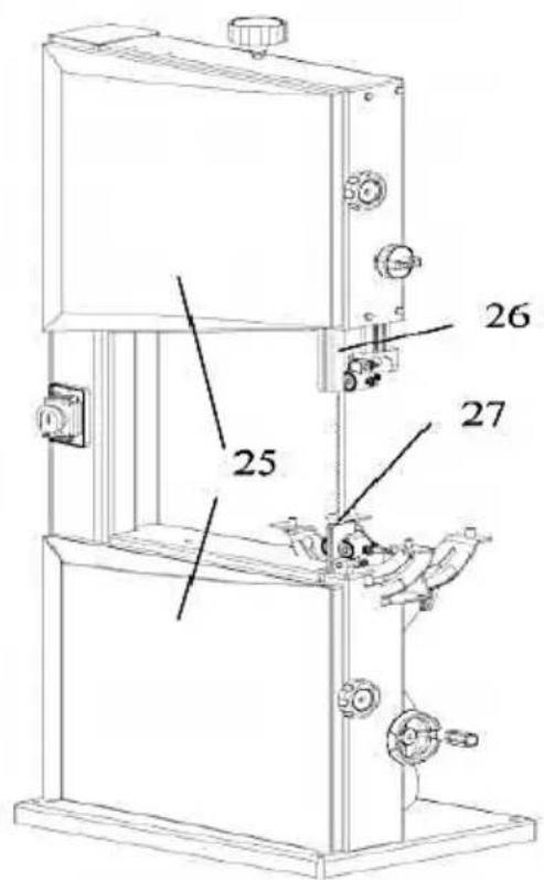
Upper Blade Guard
- The upper blade guard(26) protects against unintentional contact with the saw blade and from chips flying about. In order for the upper blade guard to provide adequate protection against contact with the band saw
blade, it must always be set as close as possible to the workpiece (max.distance 3 mm).
Lower Blade Guard
- The lower blade guard(27) protects against unintentional contact with the saw blade.
- The lower blade guard must always be in place and cover the band saw blade while the band saw is running.
Housing Doors
- The housing doors(25)protect against contact with the rotating parts inside the machine. Both housing doors must be closed while the machine is in use.
Push Stick
- The push stick serves as an extension of the hand and protects against accidental contact with the saw blade.
- The push stick must always be used if the distance between band sa blade and a rip fence is less than 120 mm. Guide the push stick at a angle of 20^ 30^ against the saw table's surface.
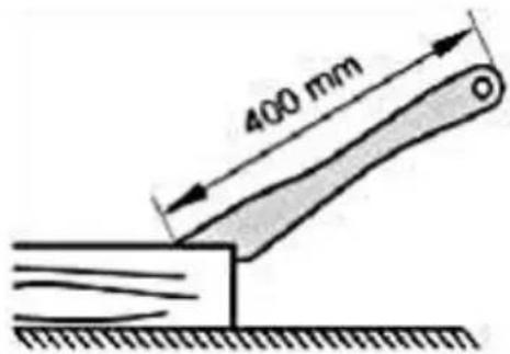
- When the push stick is not used it can be stored on the push stick holder provided at the band saw frame. Replace push stick if damaged
TRANSPORT
● Set upper blade guide to its lowest position.
- Remove projecting accessories.
- When shipping, use original packing if possible.
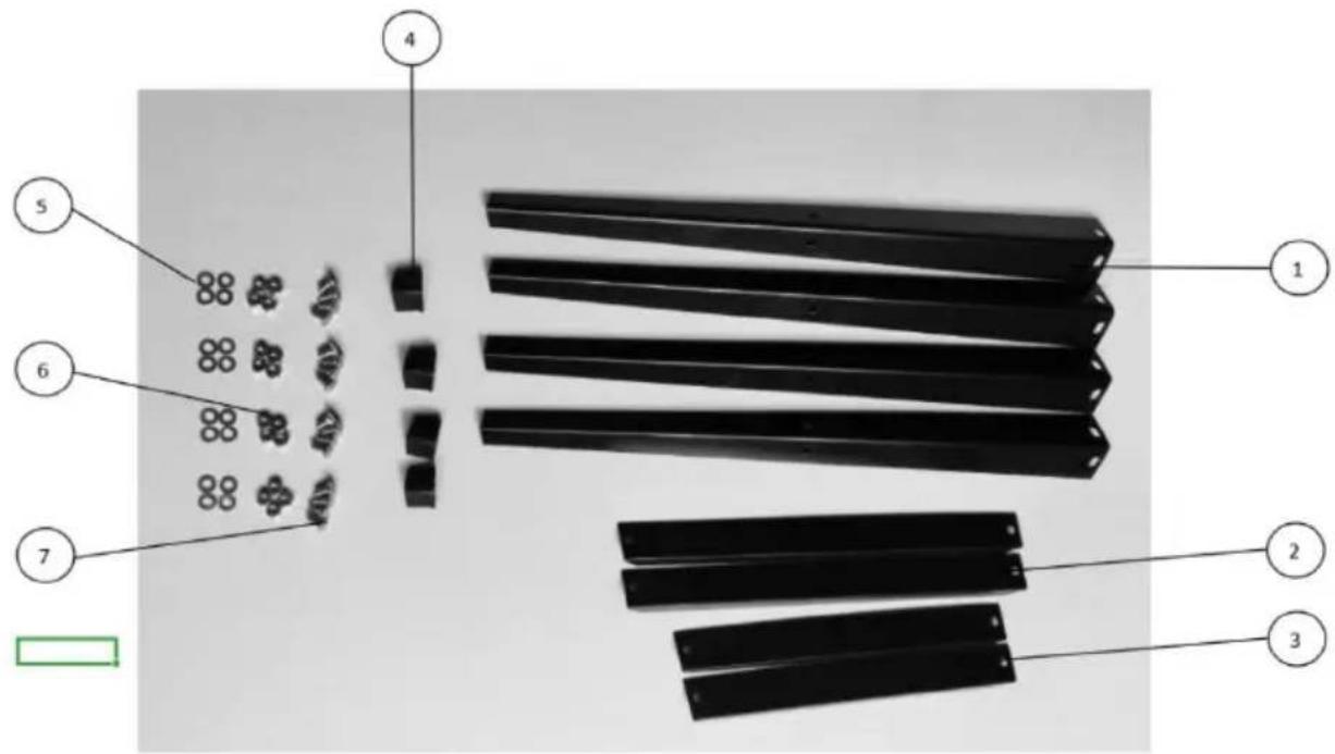
MACHINE DETAILS
Final Assembly and Installation.
Unpack machine and check for any visible damage which may have occurred during transport. If a damage is detected notify your dealer immediately.
This machine is shipped partly disassembled. Saw table and rip fence guide have to be installed prior to use.
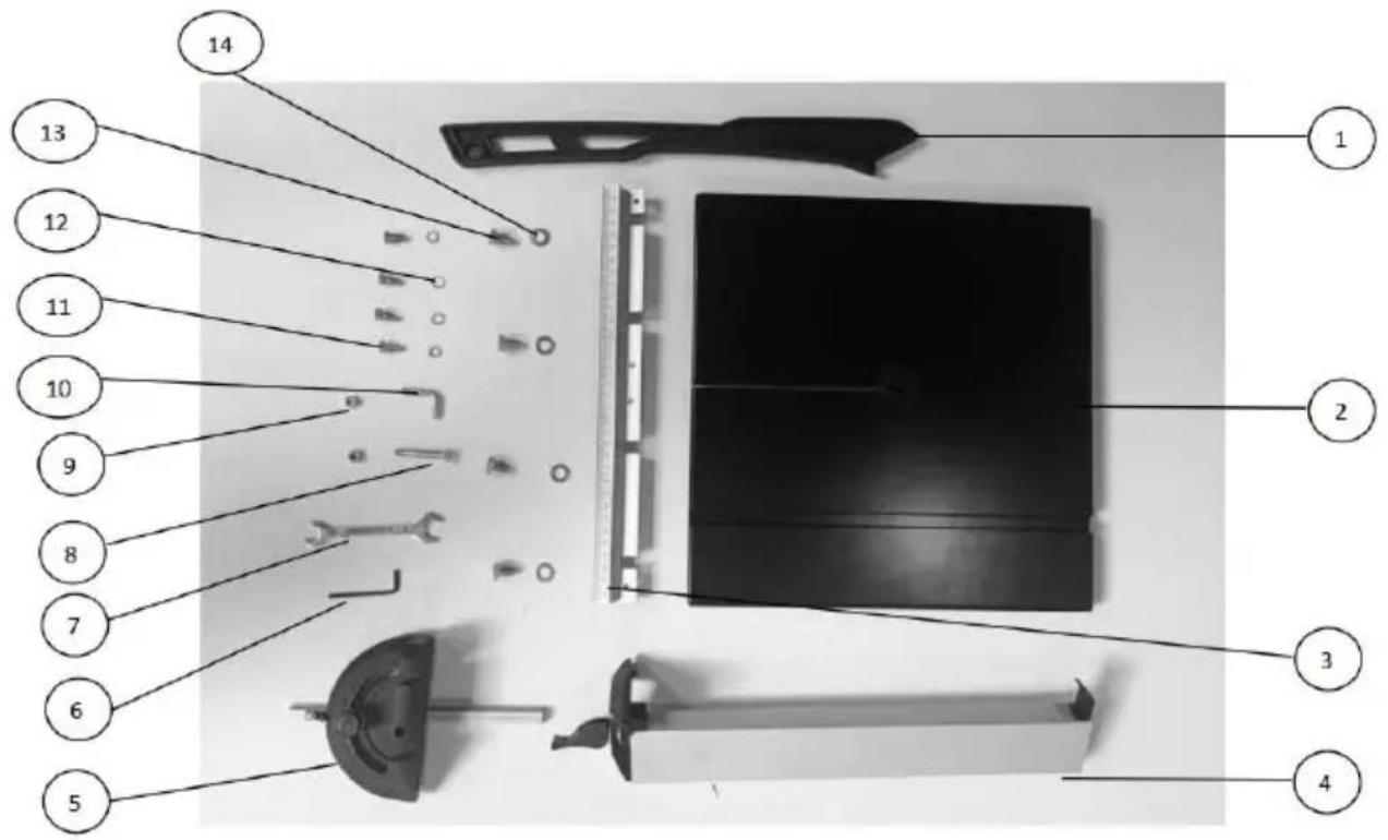
Standard accessories
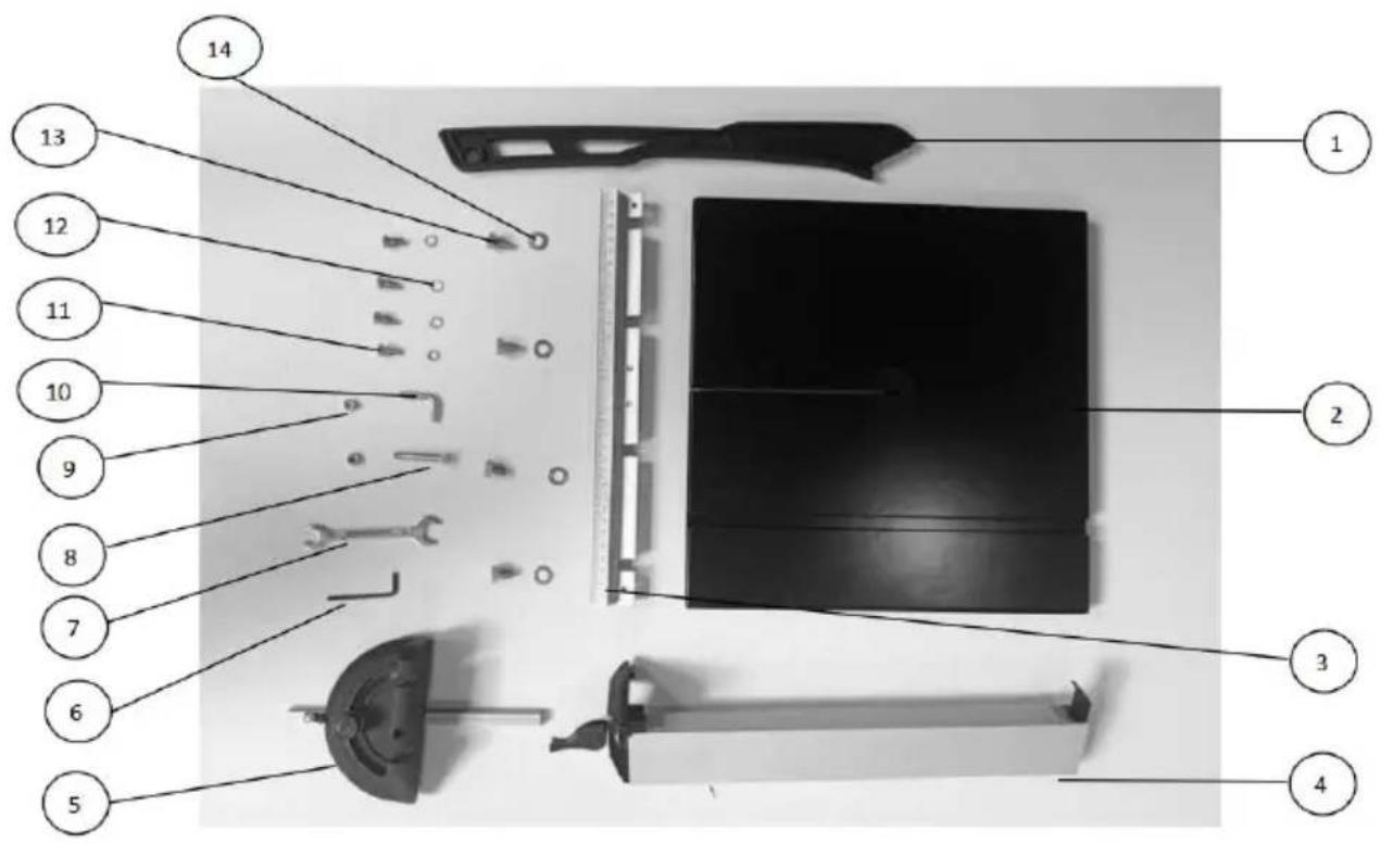
| PART NO. | DESCRIPTION | QTY |
| 1 | Push Stick | 1 |
| 2 | Saw Table | 1 |
| 3 | Fence Guide Extrusion | 1 |
| 4 | Rip Fence | 1 |
| 5 | Mitre Fence | 1 |
| 6 | Allen Wrench SW 3 | 1 |
| 7 | Wrench | 1 |
| 8 | Hex.Hd.Bolt M6×40 | 1 |
| 9 | Hex.Nut M6 | 2 |
| 10 | “L” screw | 1 |
| 11 | Hex.Hd.Bolt M6×16 | 4 |
| 12 | Ext.Lock Washer | 4 |
| 13 | Hex.Hd.Bolt M8×12 | 4 |
| 14 | Washer 8 | 4 |
Stand accessories

| PART NO. | DESCRIPTION | QTY |
| 1 | Leg | 4 |
| 2 | Cross Brace (Long) | 2 |
| 3 | Cross Brace (Short) | 2 |
| 4 | Foot Pad | 4 |
| 5 | Carriage Bolt M8 X 16 | 16 |
| 6 | Hex.Nut M8 | 16 |
| 7 | Washer 8 | 16 |
Assembly
| Fit food pad to the underside of the leg. |  | |
| Fit leg to the underside of the saw with 8 Carriage Bolt M8 × 16, 8 Washer and 8 Hex.Nut M8. |  | |
| Fit cross brace(long) to the leg with 4 Carriage Bolt M8 × 16, 4 Washer and 4 Hex.Nut M8.Fit cross brace(short) to the leg with 4 Carriage Bolt M8 × 16, 4 Washer and 4 Hex.Nut M8. | 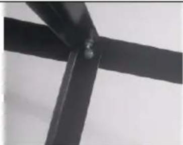 |
| Take care that screws are not tightened at same time. Thus it is easier to position mounting holes and fix the screws. | |
| Installing the Saw Table1. Fit limit stop screw to the underside of the low house.2. Guide saw table over the band saw blade and place it on the table trunnion.3. Install to trunnion with 4 each serrated lockwasher and hexagon head screw M6x16. |  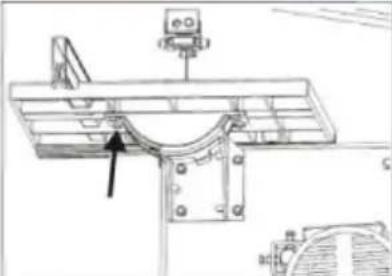 |
| Aligning the Saw TableThe saw table needs to be aligned in two planes.Laterally,in order for the blade to run dead centre through the table At right angles to the band saw blade. | |
| Saw Table Lateral Alignment1. Loosen the four fastening screws that hold the lower support of table trunnio2. Align the working table so that the blade runs through the centre of the table insert's slot.3. Tighten the four fastening screws again | 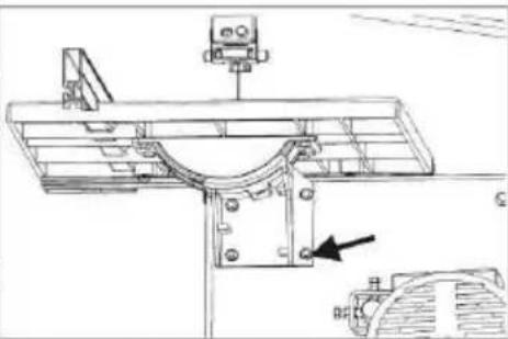 |
| Aligning the Working Table at Right Angles to the Band Saw Blade1. Raise upper blade guide fully.Check band saw blade tension.2. Loosen the lock lever.3. Using a try square,set the table at right angles to the blade and tighten the loc lever again. | 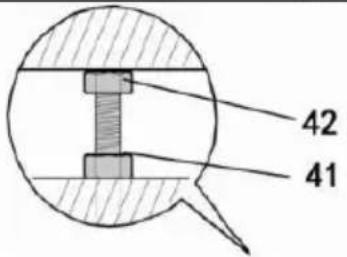 |
| 4. Loosen locking nut(41)and adjust limit stop screw(42)until it touches the working table.5. Tighten the locking nut. | 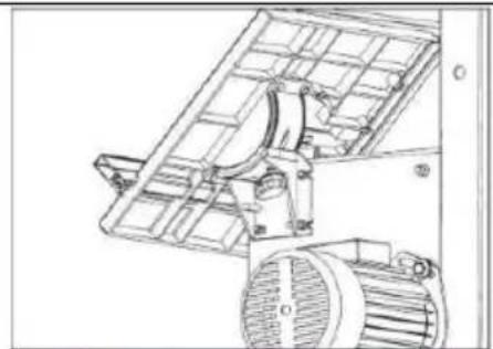 |
| Installing the Fence Guide Extrusion Fasten the fence guide extrusion with four screws and washers to the saw table. |  |
| Installing the Rip Fence1. The rip fence can be used on both side of the blade.2. Place rip fence on the rip fence guide.Tighten the lock lever of the rip. |  |
| Installing the Push Stick Holder1. Turn a hexagon nut on a cap screw,all way up to the unthreaded part of the shank.2. Turn cap screw into the hole on the side of the band saw.3. Tighten hexagon nut hand-tight only.4. Hang push stick on the cap screw when not in use. | 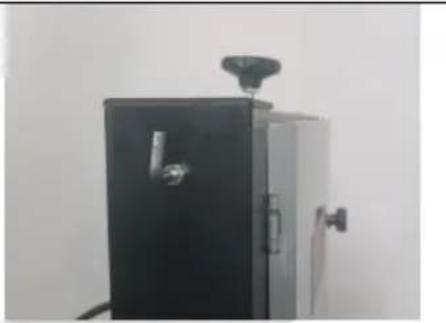 |
 | |
| The mitre fence is inserted into the table s from the table's front edge | 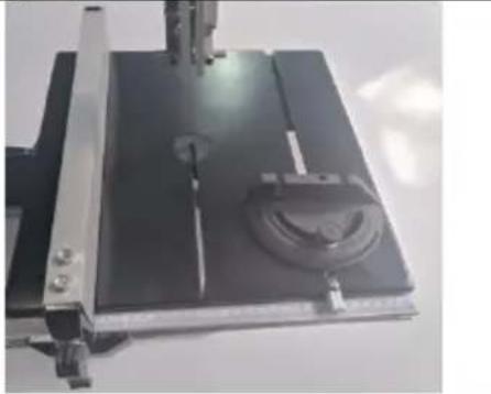 |

Note: In this chapter, the essential operating elements of the machine are introduced.
The proper use of the machine is described in chapter"Operation".Read this chapter before using the saw for the first time.
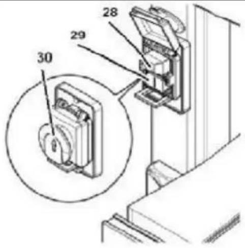
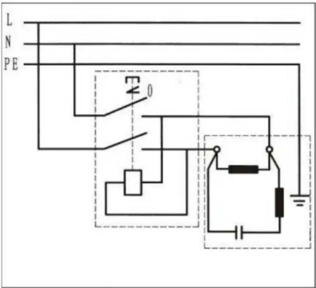
ON/OFF Switch with Emergency Stop
- To start=press the green switch button(29).
- To stop=press the red switch button(28)or the cover(30)of the ON/OFF switch.
- In the event of a voltage failure an undervoltage relay trips. This prevents the machine from starting when the power is restored. To restart, the green switch button must be pressed.
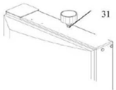
Setting Knob for Band Saw Blade T
- With the setting knob(31)the band saw blade tension is corrected,if necessary:
- Turning the setting knob clockwise increases the blade tension.
- Turning the setting knob counterclockwise reduces the blade tension.
Setting Knob for Blade Tracking Adjustment
- With the setting knob(33)the tilt of the upper band saw wheel can be adjusted necessary.This tracking adjustment is required to have the blade run dead center on the rubber tyres of the band saw wheels.
- Turning clockwise=blade moves to the rear.
- Turning counter-clockwise=blade moves to the front.
natural_image
Technical line drawing of a mechanical setup with a cylindrical component and a base, no text or symbols present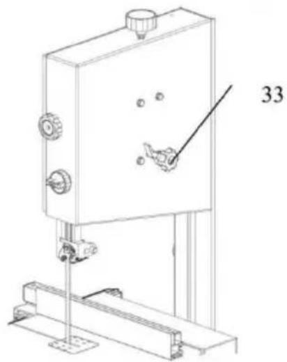
natural_image
Technical line drawing of a mechanical device with no visible text or symbols| Saw Table TiltAfter loosening the lock screw(35)the saw table(36)tilts steplessly through 45°against the blade. | 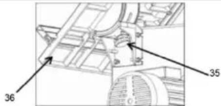 |
| Rip FenceThe rip fence(37)clamps to the front of the bandsaw table;The rip fence can be used both sides of the blade. | 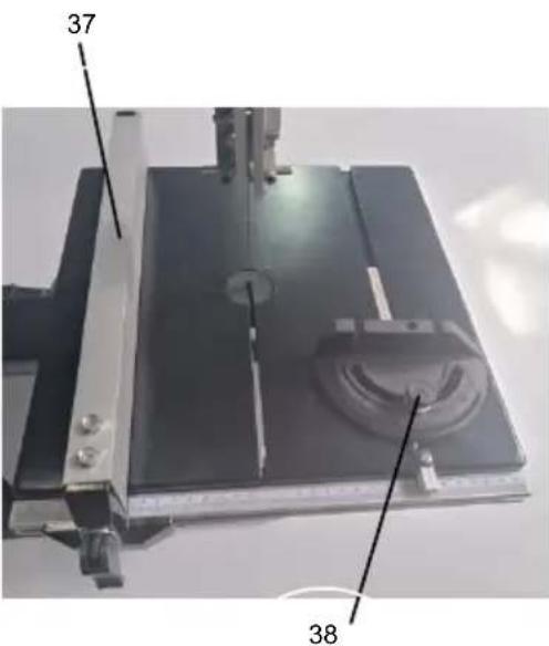 |
| Mitre FenceThe mitre fence is inserted into the table from the table's front edge.For mitre cuts mitre fence turns to60°in both directions F 45°and 90°miters positive stops are provided.To set a mitre angle:loosen lock handle(38)by turning it counter-clockwise.Risk of injury!When cutting with th mitre fence the lock handle must firmly tightened. | |
| With the setting Hex.Hd.Bolt(40)and nut(39) the tilt of the lower band wheel can be adjusted,if necessary.This tracking adjustment is required to have the blade run dead center on the rubber tyres the band saw wheels. | 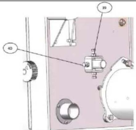 |
INITIAL OPERATION

Danger!Start the saw only after the following preparations ar
completed:
-The saw is securely mounted;
-The saw table is installed and aligned; -
The belt tension was checked;
-Safety devices have been checked. Connect the saw to the mains
supply only after all of the above preparations are completed! Otherwise there is a risk of an unintentional starting of the saw, which can cause severe personal injury.
Dust Collector Connection

Danger!Dust of certain timber species(e.g.oak,beech,and ash) can cause cancer when inhaled: always use a dust collector with working in enclosed spaces (air speed at the saw's dust extraction port ≥ 20 m/s).

Caution!Operation without a dust collector is only possible:
-Outdoors;
-For short-term operation(up to max.30 minutes); -
With dust respirator.
-If no dust collector is used chips will accumulate, which need to be removed periodically.
Connect dust collector or industrial vacuum with a suitable adaptor to the dust extraction port.
Tensioning the Band Saw Blade

Danger! Too much tension can cause the band saw blade to break. Too little tension can cause the driven band saw wheel to and the band saw blade to stop.
-
Raise upper blade guide fully(see"Operation").
-
Checking the blade tension:-Check tension by pushing with a finger, halfway between table and upper blade guide, against the side of the blade (the blade should flex not more than 1-2 mm).
-
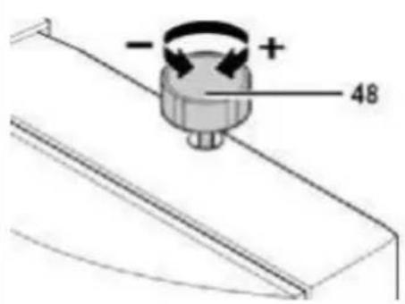
Correct tension if necessary: turning the setting knob(48) counter-clockwise increases the blade tension. Turning the setting knob(48) counter-clockwise reduces the blade tension.
Connection to Power Mains

Danger!High Voltage Operate the saw only in a dry
environment.
Operate the saw only on a power source matching the following requirements(see also"Technical Specifications"):
● Mains voltage and system frequency conform to the voltage and frequency shown on the machine's nameplate;
● Fuse protection by a residual current operated device(RCD)of 30 mA sensitivity;
● Outlets properly installed, earthed and tested;

Note:
Check with your local Electricity Board or your electrician if in doubt whether your house service connection meets the requirements.
- Make sure the power supply cable is out of the way, so that it does not interfere with the work and does not pose a tripping hazard or will get damaged.
- Protect the power supply cable from heat, aggressive liquids and sharp edges.
- Use only rubber-insulated extension cables of sufficient lead cross section(3 x 1.5 mm2, for machines with 3-phase motor: 5 x 1.5 mm2).
-
Do not pull on the power supply cable to unplug.
-
When the saw is assembled and all safety devices are installed, connected to the power supply.
-
Start saw briefly and turn OFF immediately again.
-
Check the band saw blade's direction of rotation: in the cutting area it must run from the top downwards.
- If the band saw blade turns in the wrong direction, unplug the power supply cable at the saw.
- Have the electrical connection changed by a qualified electrician!
Connection to Power Mains
OPERATION

Danger! To reduce the risk of personal injury as much as possible, the following safety recommendations should be observed when operating the saw.
Use personal protection gear:
- Dust respirator;
● Hearing protection; - Safety goggles.
Cut only one workpiece at a time.
Always hold the workpiece down on the table.
Do not jam the workpiece.
Do not attempt to stop the band saw blade by pushing the workpiece against its side.
If the type of work requires, use the following:
- Work support for long stock, which would otherwise fall off the table or completion of the cut;
- Push stick-if distance rip fence-band saw blade d120 mm;
- Dust collector;
- An appropriate jig when cutting round stock, to keep it from turning;
natural_image
Simple line drawing of a cylindrical object mounted on a square base with a rod inserted, no text or symbols present.● A suitable guide for firm support when cutting thin stock lay on edge.
natural_image
Isometric line drawing of a wooden plank and support structure on a flat base (no text or symbols)Before starting work, check to see that the following are in proper working order:
● Band saw blade;
● Upper and lower blade guard.
- Replace damaged parts at once!
- Assume correct work position(the band saw blade's teeth must point towards the operator).
- Never cut several workpieces at the same time, and also, any bundles containing several individual pieces. Risk of personal injury if individual pieces are caught by the saw blade uncontrolled.

Drawing-in/trapping hazard!
- Do not wear loose clothing, jewellery, or gloves, which may get caught and wound up by revolving machine parts. Contain long hair with a hairnet.
- Never cut stock to which ropes, cords, strings, cables and wires are attached or which contain such materials.
Band Saw Settings
| Blade GuidingThe saw blades guide of this band s model BAS 250 ensure an exact guiding of the blade for clean cuts. When using narrow blades ensure tha the lower blade guide positively supports the blade from both sides a the rear.Set the bearings of the upper blade guide to within approx. 0.5 mm of the blade, and the rear bearing against the back of the blade , just clear of it. D not set the bearing too close, as the friction generates heat, which may ha an adverse effect on the bearings an the saw blade as well. |  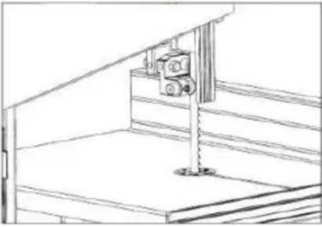 |
| Setting the Cutting HeightThe upper blade guide should always be set as close as practical against t work. To adjust, turn the knob nut at side of the upper wheel housing, and Tighten wig nut aft er setting.Set upper blade guide 3 mm above workpiece. | 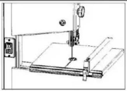 |
| Saw Table TiltFor bevel cuts the saw table tilts steplessly through 45. To tilt, loosen the knob on the table trunnions, set table to the required angle and tighte the knob again.It is recommended to verify the corre angle setting by making trial cuts in scrap wood. | 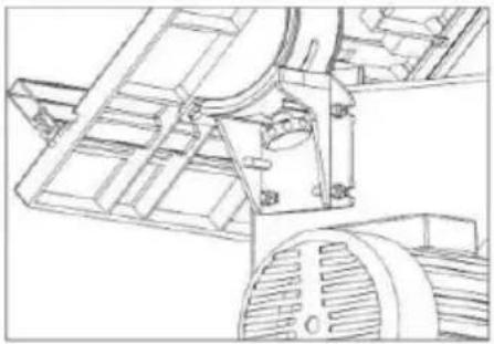 |
Speed Adjustment
-
Use a wrench to loosen the two bolts shown and turn the motor counterclockwise.
-
After the belt is loosened, adjust the position of the belt in the motor wheel and driven wheel to achieve speed regulation.
-
After the speed is adjusted, turn the motor clockwise, belt up and lock the bolt.
natural_image
Two views of an industrial machine: top shows a motor with attached components, bottom shows a circular fan with six blades (no visible text or symbols)Safety Information
1) Choose and install a table insert extrusion suitable for the type of cut be performed:
● Table insert extrusion with a narrow slot for standard cross-cuts only;
● Table inserts extrusion with a beveled slot for bevel cuts also.
2) Adjust the band saw blade speed.
3) If necessary, adjust the table tilt.

Risk of kickback(workpiece is caught by the band saw blade and thrown against the operator)! Do not jam any workpieces.
4) Select rip fence and table tilt for the type of cutting operation to be carried out.
5) Set upper blade guide 3 mm above the workpiece.

Note:Always make a trial cut in a piece of scrap to verify settings;correct if necessary before cutting the workpiece.
6) Place workpiece on the saw table.
7) Plug in.
8) Start saw.
9) Cut workpiece in a single pass.
10) Switch off if no further cutting is to be done immediately afterwards.
CAREAND MAINTENANCE

Danger!Prior to all servicing:
- Switch machine OFF.
- Unplug power cable.
● Wait until the saw has come to a complete stop. - Check that all safety devices are operational again after each service.
- Replace defective parts, especially safety devices, only with genuine replacement parts. Parts not tested and approved by the equipment manufacturer can cause unforeseen damage.
● Changing and Setting the Saw Blade
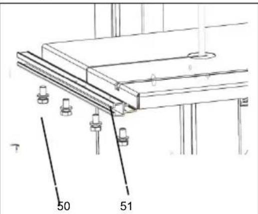
- Loosen the four screws(50)and remove the fence guide extrusion(51).
- Open both housing doors.
- Set the upper blade guide(55)to i lowest position.
- Then slacken the blade tension by turning the handwheel(48) on top the upper wheel housing. Remove the bladeguide it through
● The slot in the saw table
● The blade guard on the upper blade guide
● The blade cover on the saw housing(54)and The blade guides.
- Fit a fresh band saw blade.Observ correct position:the teeth point towards the front(door)side of the saw.
| 6. Center band saw blade on the rubber tyres of the band saw wheels.7. Tighten quick release lever until blade no longer slip off the band saw wheels.8. Close both housing doors.9. Then:● Tension band saw blade(see"Initia operation").● Align band saw blade(see"Care and maintenance");● Align blade guides(see"Care and maintenance");● Let saw test run for at least one minute;● Stop saw,unplug and recheck settings. | 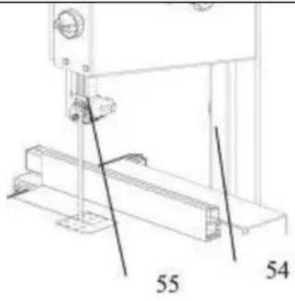 |
| Aligning the Band Saw BladeIf the band saw blade does not run the centre of the rubber tyres,the tracking needs to be corrected by adjusting the tilt of the upper band saw wheel:1. Loosen lock nut(56).2. Turn setting knob(57):-Turn setting knob(57)clockwise if the band saw blade runs towards the front of the saw.-Turn setting knob (57)counter clock wise if the band saw blade runs tow the rear of the saw.3. Tighten lock nut(56). | 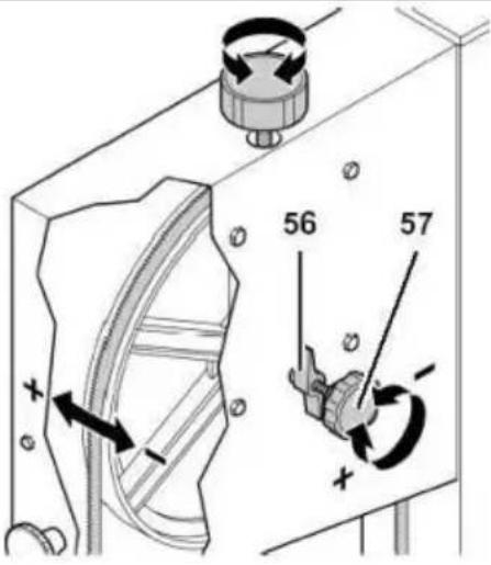 |
| Aligning the Upper Blade GuideThe upper blade guide consists of:● Athrust bearing(supporting the | |
| band saw blade from the rear)● Two guide bearings(providing lateral support).All bearings need to be readjusted at every band saw blade change and/or tracking adjustment. | 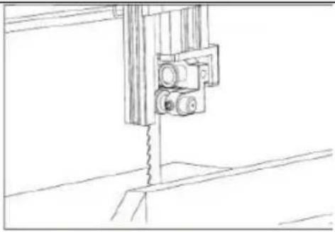 |
| Aligning the Lower Blade GuideThe lower blade guide consists of● Athrust bearing(supporting the band saw blade from the rear)● Two pilot pin providing lateral.These parts need to be readjusted at every band saw blade change or tracking | |
| Replacing the Band Saw TyrePeriodically check band saw tyres for wear.Replace only in pairs:1. Remove band saw blade.2. Lift band saw tyre with a small screwdriver,then pull off the band saw wheel.3. Mount new band saw tyres and reinstall the band saw blade. | 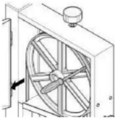 |
| Replacing the Table InsertThe table insert needs replacement when its slot has become enlarged o damaged.1. Remove table insert(61)from saw table(push up from underneath).2. Fit new table insert. | 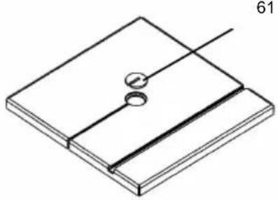 |
| Cleaning the Saw1. Open the housing doors.2. Remove chips and sawdust with brush or vacuum cleaner.3. Close the housing doors. |
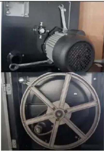
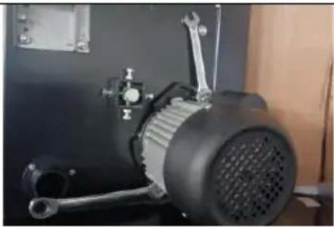
Belt Replacement
-
Use a wrench to loosen the two bolts shown and turn the motor counterclockwise.
-
Loose the belt.
-
Loosen the upper part of the band saw up tight knob, loosen the sa blade.
-
Loosen the spring with a spring clamp.
-
Take off the lower wheel and replace the belt.
natural_image
Close-up of a mechanical electric motor with visible blades and mounting bracket (no text or symbols)
natural_image
Close-up of a metallic fan or impeller with six blades, mounted on a dark mechanical frame (no visible text or symbols)
natural_image
Close-up of a black knob pressing down on a white surface, with no visible text or symbols.
natural_image
Close-up of a metallic circular mechanical component with six spokes, mounted on a dark panel (no visible text or symbols)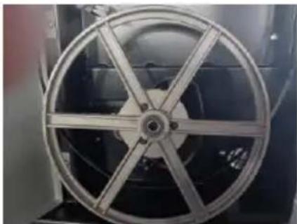
natural_image
Close-up of a metallic fan or impeller with six blades, no visible text or symbolsStorage

Danger!Store saw where
- It cannot be used or tampered with by unauthorized persons and
- Nobody can get hurt by the machine.

Note:
The ON/OFF switch can be safeguarded by a padlock.

Caution!
Do not store the saw outdoors, in unprotected areas or in damp or wet locations.
REPAIRS

Danger!
Repairs to electric tools must be carried out by qualified electricians only! Electric tools in need of repair can be sent to the service center of your country. Refer to the spare parts list for the address.
Please attach a description of the fault to the electric tool.
ENVIRONMENTAL PROTECTION
All packaging materials are 100% recyclable. Worn out power tools and accessories contain considerable amounts of valuable raw and rubber materials, which can be recycled.
These instructions are printed on paper produced with elemental chlorine-free bleaching process.

Danger!
Before carrying out any fault service or maintenance work always:
- Switch machine OFF
- Unplug power cable.
● Wait until the band saw blade has come to a complete stop.
Check to see that all safety devices are operational after each fault service
Motor does not run
Under voltage relay tripped by power failure:
- Switch on again.
No mains voltage
- Check cables, plug, outlet and mains fuse.
Motor overheated, e.g. by a blunt band saw blade or chip build-up in the housing:
- Remove cause for overheating, let cool down for a few minutes, then start again.
Band saw blade wanders off the line of cut or runs off the band wheels
Band saw blade is not running dead center on the band saw wheels:
- Correct tracking(see"Care and maintenance").
Band saw blade breaks
Incorrect tension:
- Correct band saw blade tension(see"Initial operation").
Load too high:
Reduce pressure against band saw blade(reduced feed speed).
Incorrect band saw blade:
- Replace band saw blade(see"Care and maintenance"): Thin stock=narrow band saw blade Thick stock=wide band saw blade.
Band saw blade warped
Load too high:
● Avoid lateral pressure on the band saw blade.
Saw vibrates
Insufficient mounting:
- Fasten saw properly to a suitable surface(see"Initial operation").
Saw table loose:
- Align and fasten saw table.
Motor mount loose:
- Check fastening screws, tighten if necessary.
Dust extraction port blocked
No dust collector connected or suction capacity insufficient:
- Connect a dust collector or increase suction capacity(air speed≥20 m/sec at dust extraction port).
TECHNICAL SPECIFICATIONS
| Power | 370W |
| Max. Throat Width | 245 mm |
| Max.Cutting Height | 160 mm |
| Sawblade Length | 1832 mm |
| Sawtable Size | 340 x 335 mm |
| Max.Sawblade Speeds(50 Hz) | 730 m/min |
| Max.Sawblade Speeds(60 Hz) | 890 m/min |
| N.W. | 28.8 kg |
| G.W. | 32 kg |
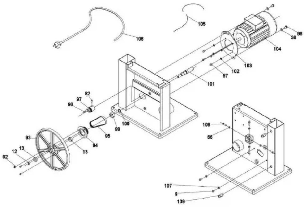
EXPLODEDVIEW DRAWINGAND PART
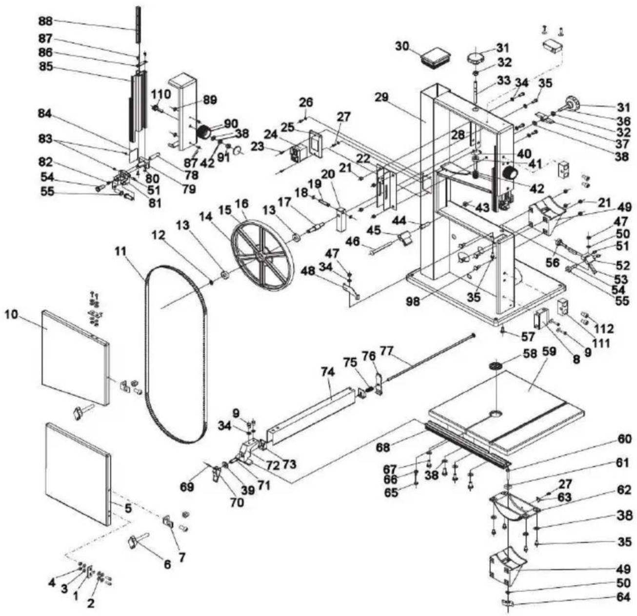


SPARE PARTS LIST/EXPLODEDVIEW DRAWING
| ITEM | PART NO. | Description | Q'ty |
| 1 | DJ31703026 | Insert Slice | 2 |
| 2 | GB/T6170/M5 | Hex Nut | 8 |
| 3 | GB/T97.1/4 | Washer | 2 |
| 4 | GB/T889.1/M4 | Hex Nut | 4 |
| 5 | DJ250B04001-1J | Door Lower | 1 |
| 6 | TYA010010 | Knob | 2 |
| 7 | DJ31505007 | Fixed Plated | 2 |
| 8 | HY50-9 | Micro Switch | 2 |
| 9 | GB5783-86 M6x10 | Hex.Hd.Bolt | 4 |
| 10 | DJ250B03001-1 | Door Upper | 1 |
| 11 | DJ250A05001F/T10/1832×6.5×0.35 6T.P.I | Bandsaw Blade | 1 |
| 12 | GB894.1-86 10 | Ring Retaining | 2 |
| 13 | GB/T276-94 6000-2Z | Ball Bearing | 4 |
| 14 | DJ250A03005 | Upper Wheel | 1 |
| 15 | DJ250A03005 | Band saw wheel | 1 |
| 16 | DJ250A04009 | Band Saw Tyre | 2 |
| 17 | DJ250A03004A | Bearing Bolt Upper | 1 |
| 18 | GB/T894.1/8 | Block Circle | 2 |
| 19 | DJ250A03007 | Pin Guide | 1 |
| 20 | DJ250A03003A | Seat Bearing Bolt Upper | 1 |
| 21 | GB/T6177.1/M6 | Hex Head Flange Nut | 8 |
| 22 | DJ200030900 | Guide Plate Assembly | 1 |
| 23 | GB819-85 M4×12 | Cross Head Screw | 2 |
| 24 | DZ04-1 | Magnetic Switch | 1 |
| 26 | GB862.2-87 4 | Ext . Lock Was Her | 4 |
| 27 | GB823-88 M4×8 | Pan Head Screw | 2 |
| 28 | DJ250A03010 | Blade Tension Er | 1 |
| 29 | BS25000000U | Band Saw Frame | 1 |
| 30 | DJ250A05002 | Lamello Plug Black | 1 |
| 31 | DJ250A03008 | Adjustable Handle | 2 |
| 32 | GB6172-86 M8 | Hex Head Thin Nut | 4 |
| 33 | DJ250A03006 | Threaded Bolt | 1 |
| 34 | GB/T97.1 6 | Washer | 8 |
| 35 | GB5783-86 M6×12 | Hex Head Bolt | 9 |
| 36 | GB5783-86 M8×45 | Hex Head Bolt | 1 |
| 37 | 31503007 | Wing Knob | 1 |
| 38 | GB/T97.1 8 | Washer | 10 |
| 39 | GB/T97.1 10 | Washer | 1 |
| 40 | DJ250A03009 | Nut | 1 |
| 41 | DJ250A03011 | Shaft | 1 |
| 42 | GB/T1792 A16 | Butterfly Spring | 18 |
| 43 | GB/T6170/M8 | Hex Head Flange Nut | 1 |
| 44 | DJ250A04014 | Space R Bushing | 1 |
| 45 | 31504015 | Brush | 1 |
| 46 | GB/T14/M8×70 | Cup Square Neck Bolt | 1 |
| 47 | GB889-86 M6 | Hex Head Lock Nut | 2 |
| 48 | DJ25004011 | Blade Guard | 1 |
| 49 | DJ250A02002 | Blade Trunnion Lower | 1 |
| 50 | GB/T96.2/6 | Washer | 2 |
| 51 | GB80-85 M6×12 | Int . Head Screw | 2 |
| 52 | DJ250A04002 | Roller Guide | 1 |
| 53 | 31504003 | Pilot Pin | 2 |
| 54 | DJ250A03021 | Thrust Bearing Shaft | 4 |
| 55 | GB/T276-94 625-2Z | Bearing | 4 |
| 56 | 31504018 | Idler Wheel Shaft | 1 |
| 57 | GB5783-86 M6×16 | Hex Head Bolt | 4 |
| 58 | DJ25002005 | Blade Fork | 1 |
| 59 | DJ250A02001G | Table | 1 |
| 60 | GB14 M6×30 | Cup Square Neck Bolt | 1 |
| 61 | DJ25002006A | Guide Piece | 1 |
| 62 | DJ250A02003 | Table T Run Ni On Upper | 1 |
| 63 | DJ250A02004 | Indicator | 1 |
| 64 | DJ250A02005 | Tension Knob | 1 |
| 65 | GB5783 M6×30 | Hex Head Bolt | 1 |
| 66 | GB6170 M6 | Hex Nut | 5 |
| 67 | GB5783 M8×12 | Hex Head Bolt | 4 |
| 68 | DJ250A02014 | Rip Fence Can I Er | 1 |
| 69 | GB879 3×16 | Roll Pin | 1 |
| 70 | DJ250A02008A-8 | Partiality Piece | 1 |
| 71 | DJ250A02008A-6 | Connect Set | 1 |
| 72 | DJ250B02008-1 | Baffle Bracket | 1 |
| 73 | DJ250A02008A-2 | Stuck Piece | 2 |
| 74 | DJ250A02008A-1 | Baffle | 1 |
| 75 | DJ250A02008A-3 | Spring | 1 |
| 76 | DJ250A02008A-4 | Clamp Board | 1 |
| 77 | DJ250A02008A-5 | Clamp Screw | 1 |
| 78 | DJ315B03024 | Fastening Shaft | 1 |
| 79 | DJ250A03014A | Seat Guide Upper | 1 |
| 80 | GB/T846 ST4.2×16 | Tapping Screw | 2 |
| 81 | DJ250A03022A | Housing Upper Guide | 1 |
| 82 | GB80-85 M6×8 | Int. Head Screw | 3 |
| 83 | GB80-85 M6×6 | Int . Head Screw | 2 |
| 84 | DJ250A03024 | Slide Board | 1 |
| 85 | DJ250A03015D | Guide Lever | 1 |
| 86 | DJ315B03031-1 | Cover Board | 1 |
| 87 | GB/T846 ST4.2×13 | Pan Head Screw | 2 |
| 88 | 31503038 | Rack | 1 |
| 89 | DJ250A03013 | Guide Piece | 2 |
| 90 | DJ250A03016B | Adjustment Knob | 1 |
| 91 | GB889-86 M8 | He D Head Nut | 1 |
| 92 | GB/T845 ST4.2×13 | Pan Head Screw | 3 |
| 93 | DJ250A04005A | Wheel Lower | 1 |
| 94 | DJ230C04002 | Pulley Lower | 1 |
| 95 | 3PJ-340 | V-Ribbed Belt | 1 |
| 97 | DJ230C04001A | Motor Pulley | 1 |
| 98 | GB/T5783 M8×16 | Cup Square Neck Bolt | 2 |
| 99 | GB6171 M14×1.5 | Hex Nut | 1 |
| 100 | GB93 14 | Spring Was Her | 1 |
| 101 | DJ250A04006 | Upper Bearing Bolt | 1 |
| 102 | GB93 6 | Spring Was Her | 4 |
| 103 | DJ25004001C | Motor Mounting Plate | 1 |
| 104 | YYL7114-T | Motor | 1 |
| 105 | DJ250A05006 | Motor Cord | 1 |
| 106 | DJ250A05005 | Power Cord | 1 |
| 107 | GB6172 M6 | Hex Head Nut | 2 |
| 108 | GB578 M6×20 | Hex Head Bolt | 4 |
| 109 | 31505010A | Relief Strain | 2 |
| 110 | DJ31703112 | Shaft | 1 |
| 111 | DJ31505008 | Fixed Block | 2 |
| 112 | GB/T70. M5×10 | Hex Head Screw | 4 |
| 114 | 31501011A-3 | Foot Pad | 4 |
| 115 | DJ250B01011-2B | Leg | 4 |
| 116 | DJ250B01011-5 | Cross Brace (Short) | 2 |
| 117 | DJ250B01011-4 | Cross Brace (Long) | 2 |
| 118 | GB/T801 M8 X 16 | Carriage Bolt | 16 |
| 119 | GB/T6170 M8 | Nut | 16 |
| 120 | GB/T97.1 8 | Washer | 16 |
VEVOR®
TOUGH TOOLS, HALF PRICE
Technical Support and E-Warranty Certificate www.vevor.com/support
VEVOR®
TOUGH TOOLS, HALF PRICE
natural_image
Exterior view of a modern office building (no signage)NEED HELP? CONTACT US!
Have product questions? Need technical support? Please feel free contact us:
Technical Support and E-Warranty Certificate www.vevor.com/support
This is the original instruction, please read all manual instructions carefully before operating. VEVOR reserves a clear interpretation of user manual. The appearance of the product shall be subject to the product you received. Please forgive us that we won't inform you there are any technology or software updates on our product.
TABLE OF CONTENTS
Accessoires standards
natural_image
Technical line drawing of a mechanical setup with a cylindrical component and a base (no text or symbols)FONCTIONNEMENT INITIAL

natural_image
Simple line drawing of a cylindrical object mounted on a rectangular base, with a vertical rod inserted (no text or symbols)natural_image
Isometric line drawing of a mechanical setup with a rectangular block and a triangular support (no text or symbols)natural_image
Technical line drawing of a mechanical assembly with a spring-loaded component (no text or symbols)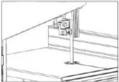
natural_image
Line drawing of a mechanical assembly or mounting bracket with no visible text or symbolsnatural_image
Technical line drawing of a mechanical assembly with no visible text or symbolsnatural_image
Technical line drawing of a mechanical assembly with no visible text or symbolsnatural_image
Close-up of an electric motor and a circular fan blade assembly (no visible text or symbols)natural_image
Close-up of an electric motor with visible blades and mounting bracket (no text or symbols)
natural_image
Close-up of a metallic fan or impeller with six blades, mounted on a dark mechanical frame (no visible text or symbols)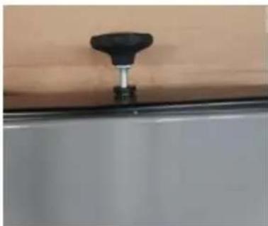
natural_image
Close-up of a black knob attached to a wall-mounted fixture (no text or symbols visible)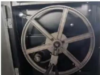
natural_image
Close-up of a metallic circular mechanical component with six arms, mounted on a black frame (no visible text or symbols)
natural_image
Close-up of a metallic fan or impeller with six blades, no visible text or symbolsStockage

VUEÉCLATÉE DESSINET PARTIE


DERECHANGE PARTIES LISTE/VUEÉCLATÉE DE
natural_image
Exterior view of a modern office building (no signage)NEED HELP? CONTACT US!
Have product questions? Need technical support? Please feel free contact us:
Technical Support and E-Warranty Certificate www.vevor.com/support
This is the original instruction, please read all manual instructions carefully before operating. VEVOR reserves a clear interpretation of user manual. The appearance of the product shall be subject to the product you received. Please forgive us that we won't inform you there are any technology or software updates on our product.
TABLE OFCONTENTS
INBETRIEBNAHME

natural_image
Simple line drawing of a cylindrical object mounted on a square base with a vertical rod, no text or symbols present.natural_image
Isometric line drawing of a mechanical setup with a wooden block and support bracket (no text or symbols)natural_image
Close-up of a mechanical electric motor with visible blades and mounting bracket (no text or symbols)
natural_image
Close-up of a metallic fan or impeller with six blades, mounted on a dark mechanical frame (no text or symbols visible)
natural_image
Close-up of a black knob pressing down on a white surface, with no visible text or symbols.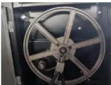
natural_image
Close-up of a metallic circular mechanical component with six spokes, mounted on a dark frame (no visible text or symbols)
natural_image
Close-up of a metallic industrial fan or impeller with six blades, no visible text or symbolsLagerung


natural_image
Exterior view of a modern office building (no signage)NEED HELP? CONTACT US!
Have product questions? Need technical support? Please feel free contact us:
Technical Support and E-Warranty Certificate www.vevor.com/support
This is the original instruction, please read all manual instructions carefully before operating. VEVOR reserves a clear interpretation of user manual. The appearance of the product shall be subject to the product you received. Please forgive us that we won't inform you there are any technology or software updates on our product.
TABLE OFCONTENTS
natural_image
Technical line drawing of a mechanical component with a cylindrical component and mounting bracket (no text or symbols)natural_image
Simple line drawing of a cylindrical object mounted on a square base with a vertical rod, no text or symbols present.natural_image
Isometric line drawing of a mechanical setup with a rectangular block and a triangular support (no text or symbols)natural_image
Close-up of a mechanical electric motor with visible blades and mounting bracket (no text or symbols)
natural_image
Close-up of a metallic fan or impeller with six blades, mounted on a dark mechanical frame (no visible text or symbols)
natural_image
Close-up of a black knob pressing down on a white surface, with no visible text or symbols.
natural_image
Close-up of a metallic circular mechanical component with six spokes, mounted on a dark panel (no visible text or symbols)
natural_image
Close-up of a metallic fan or impeller with six blades, no visible text or symbolsMagazzinaggio

VISTAESPLOSA DISEGNOE PARTE


RICAMBIO PARTI ELENCO/VISTAESPLOSA DISE
natural_image
Exterior view of a modern office building (no signage)NEED HELP? CONTACT US!
Have product questions? Need technical support? Please feel free contact us:
Technical Support and E-Warranty Certificate www.vevor.com/support
This is the original instruction, please read all manual instructions carefully before operating. VEVOR reserves a clear interpretation of user manual. The appearance of the product shall be subject to the product you received. Please forgive us that we won't inform you there are any technology or software updates on our product.
TABLE OFCONTENTS
natural_image
Simple line drawing of a cylindrical object mounted on a square base with a vertical rod, no text or symbols present.natural_image
Isometric line drawing of a mechanical setup with two plates and a central rod (no text or symbols)natural_image
Technical line drawing of a mechanical assembly with a spring-loaded component (no text or symbols)
natural_image
Line drawing of a mechanical assembly or mounting bracket with a vertical support and base platform (no text or symbols)natural_image
Technical line drawing of a mechanical assembly with no visible text or symbolsnatural_image
Technical line drawing of a mechanical assembly with no visible text or symbolsnatural_image
Close-up of a mechanical electric motor with visible blades and mounting bracket (no text or symbols)
natural_image
Close-up of a metallic fan or impeller with six blades, mounted on a dark mechanical frame (no visible text or symbols)
natural_image
Close-up of a black knob pressing down on a white surface, with no visible text or symbols.
natural_image
Close-up of a metallic circular mechanical component with six spokes, mounted on a dark panel (no visible text or symbols)
natural_image
Close-up of a metallic fan or impeller with six blades, no visible text or symbolsAlmacenamiento

VISTAEXPLOTADA DIBUJOY PARTE


REPUESTO REGIONES LISTA/VISTA EN DESPIE DIBUJO
| ARTÍ CULO | NÚMERO DE PIEZA | Descripción | Canti dad |
| 1 | DJ31703026 | Insertar rebanada | 2 |
| 2 | GB/T6170/M5 | Tuerca hexagonal | 8 |
| 3 | GB/T97.1/4 | Arandela | 2 |
| 4 | GB/T889.1/M4 | Tuerca hexagonal | 4 |
| 5 | DJ250B04001-1J | Puerta inferior | 1 |
| 6 | TYA010010 | Perilla | 2 |
| 7 | DJ31505007 | Placa fija | 2 |
| 8 | HY50-9 | Microinterruptor | 2 |
| 9 | GB5783-86 M6x10 | Perno de cabeza hexagonal | 4 |
| 10 | DJ250B03001-1 | Puerta superior | 1 |
| 11 | DJ250A05001F/T10/1832× 6.5×0.35 6T.PI | Hoja de sierra de cinta | 1 |
| 12 | GB894.1-86 10 | Anillo de retención | 2 |
| 13 | GB/T276-94 6000-2Z | Cojinete de bolas | 4 |
| 14 | DJ250A03005 | Rueda superior | 1 |
| 15 | DJ250A03005 | Rueda de sierra de cinta | 1 |
| 16 | DJ250A04009 | Neumático para sierra de cinta | 2 |
| 17 | DJ250A03004A | Perno de cojinete superior | 1 |
| 18 | GB/T894.1/8 | Círculo de bloques | 2 |
| 19 | DJ250A03007 | Guía de pines | 1 |
| 20 | DJ250A03003A | Perno del cojinete del asiento superior | 1 |
| 21 | GB/T6177.1/M6 | Tuerca de brida de cabeza hexagonal | 8 |
| 22 | DJ200030900 | Conjunto de placa guía | 1 |
| 23 | GB819-85 M4×12 | Tornillo de cabeza cruzada | 2 |
| 24 | DZ04-1 | Interruptor magnético | 1 |
| 26 | GB862.2-87 4 | Ext. Lock era ella | 4 |
| 27 | GB823-88 M4×8 | Tornillo de cabeza plana | 2 |
| 28 | DJ250A03010 | Tensión de la cuchilla Er | 1 |
| 29 | BS25000000U | Marco de sierra de cinta | 1 |
| 30 | DJ250A05002 | Tapón de láminas negro | 1 |
| 31 | DJ250A03008 | Mango ajustable | 2 |
| 32 | GB6172-86 M8 | Tuerca fina de cabeza hexagonal | 4 |
| 33 | DJ250A03006 | Perno roscado | 1 |
| 34 | GB/T97.1 6 | Arandela | 8 |
| 35 | GB5783-86 M6×12 | Perno de cabeza hexagonal | 9 |
| 36 | GB5783-86 M8×45 | Perno de cabeza hexagonal | 1 |
| 37 | 31503007 | Perilla de ala | 1 |
| 38 | GB/T97.1 8 | Arandela | 10 |
| 39 | GB/T97.1 10 | Arandela | 1 |
| 40 | DJ250A03009 | Tuerca | 1 |
| 41 | DJ250A03011 | Eje | 1 |
| 42 | GB/T1792 A16 | Primavera de mariposas | 18 |
| 43 | GB/T6170/M8 | Tuerca de brida de cabeza hexagonal | 1 |
| 44 | DJ250A04014 | Buje espacial R | 1 |
| 45 | 31504015 | Cepillar | 1 |
| 46 | GB/T14/M8×70 | Perno de cuello cuadrado de copa | 1 |
| 47 | GB889-86 M6 | Tuerca de seguridad de cabeza hexagonal | 2 |
| 48 | DJ25004011 | Protector de cuchilla | 1 |
| 49 | DJ250A02002 | Muñón de la cuchilla inferior | 1 |
| 50 | GB/T96.2/6 | Arandela | 2 |
| 51 | GB80-85 M6×12 | Tornillo de cabeza interior | 2 |
| 52 | DJ250A04002 | Guía de rodillos | 1 |
| 53 | 31504003 | Pin de piloto | 2 |
| 54 | DJ250A03021 | Eje de cojinete de empuje | 4 |
| 55 | GB/T276-94 625-2Z | Cojinete | 4 |
| 56 | 31504018 | Eje de rueda loca | 1 |
| 57 | GB5783-86 M6×16 | Perno de cabeza hexagonal | 4 |
| 58 | DJ25002005 | Horquilla de cuchilla | 1 |
| 59 | DJ250A02001G | Mesa | 1 |
| 60 | GB14 M6×30 | Perno de cuello cuadrado de copa | 1 |
| 61 | DJ25002006A | Pieza guía | 1 |
| 62 | DJ250A02003 | Tabla T Ejecutar Ni En La Parte Superior | 1 |
| 63 | DJ250A02004 | Indicador | 1 |
| 64 | DJ250A02005 | Perilla de tensión | 1 |
| 65 | GB5783 M6×30 | Perno de cabeza hexagonal | 1 |
| 66 | GB6170 M6 | Tuerca hexagonal | 5 |
| 67 | GB5783 M8×12 | Perno de cabeza hexagonal | 4 |
| 68 | DJ250A02014 | ¿Puedo cortar una valla? | 1 |
| 69 | GB879 3×16 | Pasador de rodillo | 1 |
| 70 | DJ250A02008A-8 | Pieza de parcialidad | 1 |
| 71 | DJ250A02008A-6 | Conjunto de conexión | 1 |
| 72 | DJ250B02008-1 | Soporte deflector | 1 |
| 73 | DJ250A02008A-2 | Pieza atascada | 2 |
| 74 | DJ250A02008A-1 | Deflector | 1 |
| 75 | DJ250A02008A-3 | Primavera | 1 |
| 76 | DJ250A02008A-4 | Tablero de sujeción | 1 |
| 77 | DJ250A02008A-5 | Tornillo de sujeción | 1 |
| 78 | DJ315B03024 | Eje de fijación | 1 |
| 79 | DJ250A03014A | Guía del asiento superior | 1 |
| 80 | GB/T846 ST4.2×16 | Tornillo de rosca | 2 |
| 81 | DJ250A03022A | Guía superior de la carcasa | 1 |
| 82 | GB80-85 M6×8 | Tornillo de cabeza interior | 3 |
| 83 | GB80-85 M6×6 | Tornillo de cabeza interior | 2 |
| 84 | DJ250A03024 | Tabla deslizante | 1 |
| 85 | DJ250A03015D | Palanca de guía | 1 |
| 86 | DJ315B03031-1 | Tablero de cubierta | 1 |
| 87 | GB/T846 ST4.2×13 | Tornillo de cabeza plana | 2 |
| 88 | 31503038 | Estante | 1 |
| 89 | DJ250A03013 | Pieza guía | 2 |
| 90 | DJ250A03016B | Perilla de ajuste | 1 |
| 91 | GB889-86 M8 | Tuerca de cabeza en D | 1 |
| 92 | GB/T845 ST4.2×13 | Tornillo de cabeza plana | 3 |
| 93 | DJ250A04005A | Rueda inferior | 1 |
| 94 | DJ230C04002 | Polea inferior | 1 |
| 95 | 3PJ-340 | Correa acanalada en V | 1 |
| 97 | DJ230C04001A | Polea del motor | 1 |
| 98 | GB/T5783 M8×16 | Perno de cuello cuadrado de copa | 2 |
| 99 | GB6171 M14×1,5 | Tuerca hexagonal | 1 |
| 100 | GB93 14 | La primavera era suya | 1 |
| 101 | DJ250A04006 | Perno del cojinete superior | 1 |
| 102 | GB93 6 | La primavera era suya | 4 |
| 103 | DJ25004001C | Placa de montaje del motor | 1 |
| 104 | YYL7114-T | Motor | 1 |
| 105 | DJ250A05006 | Cable del motor | 1 |
| 106 | DJ250A05005 | Cable de alimentación | 1 |
| 107 | GB6172 M6 | Tuerca de cabeza hexagonal | 2 |
| 108 | GB578 M6×20 | Perno de cabeza hexagonal | 4 |
| 109 | 31505010A | Alivio de la tensión | 2 |
| 110 | DJ31703112 | Eje | 1 |
| 111 | DJ31505008 | Bloque fijo | 2 |
| 112 | GB/T70.M5×10 | Tornillo de cabeza hexagonal | 4 |
| 114 | 31501011A-3 | Almohadilla para el pie | 4 |
| 115 | DJ250B01011-2B | Pierna | 4 |
| 116 | DJ250B01011-5 | Tirante transversal (corto) | 2 |
| 117 | DJ250B01011-4 | Tirante transversal (largo) | 2 |
| 118 | GB/T801 M8 x 16 | Perno de carruaje | 16 |
| 119 | GB/T6170 M8 | Tuerca | 16 |
| 1 20 | GB/T97.1 8 | Arandela | 16 |
VEVOR®
TOUGH TOOLS, HALF PRICE
natural_image
Exterior view of a modern office building (no signage)NEED HELP? CONTACT US!
Have product questions? Need technical support? Please feel free contact us:
Technical Support and E-Warranty Certificate www.vevor.com/support
This is the original instruction, please read all manual instructions carefully before operating. VEVOR reserves a clear interpretation of user manual. The appearance of the product shall be subject to the product you received. Please forgive us that we won't inform you there are any technology or software updates on our product.
TABLEOF CONTENTS
natural_image
Close-up of a mechanical device with a black plate and metal frame, showing a tool and measurement markings (no visible text or symbols)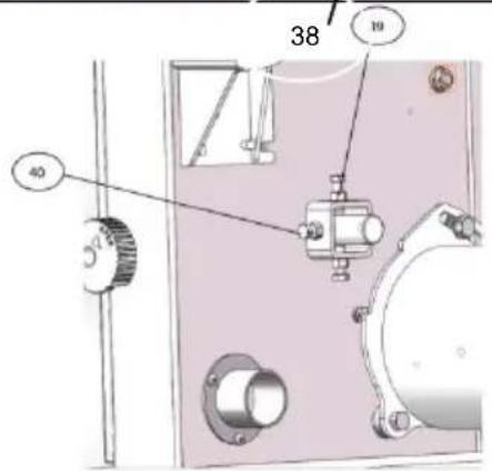
PIERWSZE DZIAŁANIE

natural_image
Simple line drawing of a cylindrical object mounted on a rectangular base, with a vertical rod inserted (no text or symbols)natural_image
Isometric line drawing of a mechanical setup with a rectangular block and a triangular support (no text or symbols)natural_image
Technical line drawing of a mechanical assembly with mounting flanges and bolts (no text or symbols)natural_image
Close-up of a metallic fan or impeller with six blades, mounted on a black industrial machine (no visible text or symbols)
natural_image
Close-up of a black knob attached to a wooden surface, with a metallic clip and flat panel below (no text or symbols visible)
natural_image
Close-up of a metallic wheel with six spokes, mounted on a black panel (no visible text or symbols)
natural_image
Close-up of a metallic circular fan or impeller with six blades, mounted on a dark base (no visible text or symbols)Składowanie

WIDOKROZBIÓRKOWY RYSUNEKI CZĘŚĆ


ZAPASOWY STRONY LISTA/WIDOK ROZŁOŻON RYSUNEK
www.vevor.com/support
VEVOR®
TOUGH TOOLS, HALF PRICE
Technisch Ondersteuning en E-garantiecertificaat www.vevor.com/support
LINTZAGER
GEBRUIKER HANDMATIG
MODEL:HBS250
natural_image
Exterior view of a modern office building (no signage)NEED HELP? CONTACT US!
Have product questions? Need technical support? Please feel free contact us:
Technical Support and E-Warranty Certificate www.vevor.com/support
This is the original instruction, please read all manual instructions carefully before operating. VEVOR reserves a clear interpretation of user manual. The appearance of the product shall be subject to the product you received. Please forgive us that we won't inform you there are any technology or software updates on our product.
TABLE OFCONTENTS
natural_image
Line drawing of a mechanical device with a knob and side ports (no text or symbols)| ONDERDEELNR. | BESCHRIJVING | Hoeveelheid |
| 1 | Duwstok | 1 |
| 2 | Zaagtafel | 1 |
| 3 | Hek gids Extrusie | 1 |
| 4 | Schutting | 1 |
| 5 | Verstek hek | 1 |
| 6 | Inbussleutel SW 3 | 1 |
| 7 | Moersleutel | 1 |
| 8 | Zeskantbout M6×40 | 1 |
| 9 | Zeskantmoer M6 | 2 |
| 10 | “ L ” schroef | 1 |
| 11 | Zeskantbout M6×16 | 4 |
| 12 | Ext.Lock Ring | 4 |
| 13 | Zeskantige HD-bout M8×12 | 4 |
| 14 | Ring 8 | 4 |
Staande accessoires
| ONDERDEELNR. | BESCHRIJVING | Hoeveelheid |
| 1 | Been | 4 |
| 2 | Kruisbeugel (lang) | 2 |
| 3 | Kruisbeugel (kort) | 2 |
| 4 | Voetkussen | 4 |
| 5 | Wagenbout M8x16 | 16 |
| 6 | Zeskantmoer M8 | 16 |
| 7 | Ring 8 | 16 |
Montage
natural_image
Technical line drawing of a mechanical assembly with a cylindrical component and mounting bracket (no text or symbols)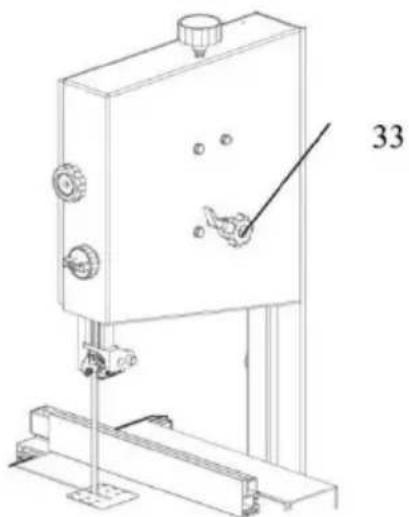
natural_image
Technical line drawing of a mechanical device with mounting bracket and control panel (no text or symbols)natural_image
Simple line drawing of a cylindrical object mounted on a square base with a vertical rod, no text or symbols present.natural_image
Isometric line drawing of a mechanical setup with a rectangular block and a triangular support (no text or symbols)natural_image
Close-up of a metallic fan or impeller with six blades, mounted on a dark mechanical base (no visible text or symbols)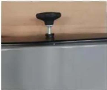
natural_image
Close-up of a black knob attached to a metallic stand on a white surface (no text or symbols visible)
natural_image
Close-up of a metallic wheel with six spokes, mounted on a black panel (no visible text or symbols)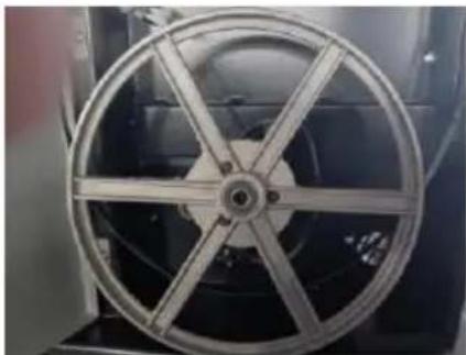
natural_image
Close-up of a metallic circular fan or impeller with six blades, mounted on a dark base (no visible text or symbols)Opslag


SPAREN ONDERDELEN LIJST/UITGEBREIDE WE TEKENING
| ITEM | ONDERDEELNR. | Beschrijving | Hoeveelheid |
| 1 | DJ31703026 | Plak invoegen | 2 |
| 2 | GB/T6170/M5 | Zeskantmoer | 8 |
| 3 | GB/T97.1/4 | Wasmachine | 2 |
| 4 | GB/T889.1/M4 | Zeskantmoer | 4 |
| 5 | DJ250B04001-1J | Deur onder | 1 |
| 6 | TYA010010 | Knop | 2 |
| 7 | DJ31505007 | Vaste plaat | 2 |
| 8 | HY50-9 | Microschakelaar | 2 |
| 9 | GB5783-86 M6x10 | Zeskantige HD-bout | 4 |
| 10 | DJ250B03001-1 | Deur Boven | 1 |
| 11 | DJ250A05001F/T10/1832×6,5×0,35 6T.PI | Lintzaagblad | 1 |
| 12 | GB894.1-86 10 | Ringbevestiging | 2 |
| 13 | GB/T276-94 6000-2Z | Kogellager | 4 |
| 14 | DJ250A03005 | Bovenste wiel | 1 |
| 15 | DJ250A03005 | Bandzaagwiel | 1 |
| 16 | DJ250A04009 | Bandzaagband | 2 |
| 17 | DJ250A03004A | Lagerbout Boven | 1 |
| 18 | GB/T894.1/8 | Blok cirkel | 2 |
| 19 | DJ250A03007 | Pin-gids | 1 |
| 20 | DJ250A03003A | Zittinglagerbout Boven | 1 |
| 21 | GB/T6177.1/M6 | Zeskantige flensmoer | 8 |
| 22 | DJ200030900 | Montage geleideplaat | 1 |
| 23 | GB819-85 M4×12 | Kruiskopschroef | 2 |
| 24 | DZ04-1 | Magnetische schakelaar | 1 |
| 26 | GB862.2-87 4 | Ext. Lock was haar | 4 |
| 27 | GB823-88 M4×8 | Pankopschroef | 2 |
| 28 | DJ250A03010 | Bladspanning Er | 1 |
| 29 | BS25000000U | Lintzaagframe | 1 |
| 30 | DJ250A05002 | Lamello Plug Zwart | 1 |
| 31 | DJ250A03008 | Verstelbare handgreep | 2 |
| 32 | GB6172-86 M8 | Dunne zeskantmoer | 4 |
| 33 | DJ250A03006 | Schroefdraadbout | 1 |
| 34 | GB/T97.1 6 | Wasmachine | 8 |
| 35 | GB5783-86 M6×12 | Zeskantbout | 9 |
| 36 | GB5783-86 M8×45 | Zeskantbout | 1 |
| 37 | 31503007 | Vleugelknop | 1 |
| 38 | GB/T97.1 8 | Wasmachine | 10 |
| 39 | GB/T97.1 10 | Wasmachine | 1 |
| 40 | DJ250A03009 | Moer | 1 |
| 41 | DJ250A03011 | Schacht | 1 |
| 42 | GB/T1792 A16 | Vlinderlente | 18 |
| 43 | GB/T6170/M8 | Zeskantige flensmoer | 1 |
| 44 | DJ250A04014 | Ruimte R-bus | 1 |
| 45 | 31504015 | Borstel | 1 |
| 46 | GB/T14/M8×70 | Kop vierkante hals bout | 1 |
| 47 | GB889-86 M6 | Zeskantige borgmoer | 2 |
| 48 | DJ25004011 | Mesbescherming | 1 |
| 49 | DJ250A02002 | Bladdraaipunt lager | 1 |
| 50 | GB/T96.2/6 | Wasmachine | 2 |
| 51 | GB80-85 M6x12 | Int. Kopschroef | 2 |
| 52 | DJ250A04002 | Rolgeleider | 1 |
| 53 | 31504003 | Pilootpen | 2 |
| 54 | DJ250A03021 | Druklager as | 4 |
| 55 | GB/T276-94 625-2Z | Handelswijze | 4 |
| 56 | 31504018 | As van het loopwiel | 1 |
| 57 | GB5783-86 M6×16 | Zeskantbout | 4 |
| 58 | DJ25002005 | Bladvork | 1 |
| 59 | DJ250A02001G | Tafel | 1 |
| 60 | GB14 M6×30 | Kop vierkante hals bout | 1 |
| 61 | DJ25002006A | Gidsstuk | 1 |
| 62 | DJ250A02003 | Tabel T Run Ni Op Boven | 1 |
| 63 | DJ250A02004 | Indicator | 1 |
| 64 | DJ250A02005 | Spanningsknop | 1 |
| 65 | GB5783 M6×30 | Zeskantbout | 1 |
| 66 | GB6170 M6 | Zeskantmoer | 5 |
| 67 | GB5783 M8×12 | Zeskantbout | 4 |
| 68 | DJ250A02014 | Rip Fence Kan ik Er | 1 |
| 69 | GB879 3×16 | Rolspeld | 1 |
| 70 | DJ250A02008A-8 | Partijdigheidsstuk | 1 |
| 71 | DJ250A02008A-6 | Verbindingsset | 1 |
| 72 | DJ250B02008-1 | Baffle-beugel | 1 |
| 73 | DJ250A02008A-2 | Vastzittend stuk | 2 |
| 74 | DJ250A02008A-1 | Verwarren | 1 |
| 75 | DJ250A02008A-3 | Lente | 1 |
| 76 | DJ250A02008A-4 | Klembord | 1 |
| 77 | DJ250A02008A-5 | Klemschroef | 1 |
| 78 | DJ315B03024 | Bevestigingsas | 1 |
| 79 | DJ250A03014A | Zittinggeleider Boven | 1 |
| 80 | GB/T846 ST4.2×16 | Tapschroef | 2 |
| 81 | DJ250A03022A | Behuizing Bovengeleider | 1 |
| 82 | GB80-85 M6×8 | Int. Kopschroef | 3 |
| 83 | GB80-85 M6×6 | Int. Kopschroef | 2 |
| 84 | DJ250A03024 | Schuifbord | 1 |
| 85 | DJ250A03015D | Geleidingshendel | 1 |
| 86 | DJ315B03031-1 | Afdekplaat | 1 |
| 87 | GB/T846 ST4.2×13 | Pankopschroef | 2 |
| 88 | 31503038 | Rek | 1 |
| 89 | DJ250A03013 | Gidsstuk | 2 |
| 90 | DJ250A03016B | Afstelknop | 1 |
| 91 | GB889-86 M8 | Hij D Kop Moer | 1 |
| 92 | GB/T845 ST4.2×13 | Pankopschroef | 3 |
| 93 | DJ250A04005A | Wiel lager | 1 |
| 94 | DJ230C04002 | Katrol Onder | 1 |
| 95 | 3PJ-340 | V-riem | 1 |
| 97 | DJ230C04001A | Motorpoelie | 1 |
| 98 | GB/T5783 M8×16 | Kop vierkante hals bout | 2 |
| 99 | GB6171 M14×1.5 | Zeskantmoer | 1 |
| 100 | GB93 14 | Lente was haar | 1 |
| 101 | DJ250A04006 | Bovenste lagerbout | 1 |
| 102 | GB93 6 | Lente was haar | 4 |
| 103 | DJ25004001C | Motormontageplaat | 1 |
| 104 | YYL7114-T | Motor | 1 |
| 105 | DJ250A05006 | Motorsnoer | 1 |
| 106 | DJ250A05005 | Stroomkabel | 1 |
| 107 | GB6172 M6 | Zeskantmoer | 2 |
| 108 | GB578 M6×20 | Zeskantbout | 4 |
| 109 | 31505010A | Ontlastingsspanning | 2 |
| 110 | DJ31703112 | Schacht | 1 |
| 111 | DJ31505008 | Vaste blok | 2 |
| 112 | GB/T70.M5×10 | Zeskantschroef | 4 |
| 114 | 31501011A-3 | Voetkussen | 4 |
| 115 | DJ250B01011-2B | Been | 4 |
| 116 | DJ250B01011-5 | Kruisbeugel (kort) | 2 |
| 117 | DJ250B01011-4 | Kruisbeugel (lang) | 2 |
| 118 | GB/T801 M8 X 16 | Wagenbout | 16 |
| 119 | GB/T6170 M8 | Moer | 16 |
| 1 20 | GB/T97.1 8 | Wasmachine | 16 |
VEVOR®
TOUGH TOOLS, HALF PRICE
Technisch Ondersteuning en E-garantiecertificaat www.vevor.com/support
VEVOR®
TOUGH TOOLS, HALF PRICE
natural_image
Exterior view of a modern office building (no signage)NEED HELP? CONTACT US!
Have product questions? Need technical support? Please feel free contact us:
Technical Support and E-Warranty Certificate www.vevor.com/support
This is the original instruction, please read all manual instructions carefully before operating. VEVOR reserves a clear interpretation of user manual. The appearance of the product shall be subject to the product you received. Please forgive us that we won't inform you there are any technology or software updates on our product.
TABLE OF CONTENTS
| DELNR. | BESKRIVNING | ANTAL |
| 1 | Push Stick | 1 |
| 2 | Sågbord | 1 |
| 3 | Stängselguide Extrudering | 1 |
| 4 | Rip staket | 1 |
| 5 | Geringsstaket | 1 |
| 6 | Insexnyckel SW 3 | 1 |
| 7 | W rench | 1 |
| 8 | Hex.Hd.Bolt M6×40 | 1 |
| 9 | Sexkantsmutter M6 | 2 |
| 10 | " L " skruv | 1 |
| 11 | Hex.Hd.Bolt M6×16 | 4 |
| 12 | Ext.Låsbricka | 4 |
| 13 | Hex.Hd.Bolt M8×12 | 4 |
| 14 | Bricka 8 | 4 |
Stativtillbehör
| DELNR. | BESKRIVNING | ANTAL |
| 1 | Ben | 4 |
| 2 | Cross Brace (lång) | 2 |
| 3 | Cross Brace (kort) | 2 |
| 4 | Fotdyna | 4 |
| 5 | Vagnsbult M8 X 16 | 16 |
| 6 | Sexkantsmutter M8 | 16 |
| 7 | Bricka 8 | 16 |
Montering
natural_image
Simple line drawing of a cylindrical object mounted on a square base with a rod, no text or symbols present.natural_image
Isometric line drawing of a mechanical setup with a wooden block and a triangular support (no text or symbols)natural_image
Two views of an industrial machine: top shows a motor with attached components, bottom shows a circular fan with six blades (no visible text or symbols)Säkerhetsinformation
Sprängvy RITNINGOCH DEL


SKONA DELAR LISTA/EXPLODEDVISNING DRAW
| PUNKT | DELNR. | Beskrivning | Antal |
| 1 | DJ31703026 | Sätt in skiva | 2 |
| 2 | GB/T6170/M5 | Sexkantsmutter | 8 |
| 3 | GB/T97.1/4 | Bricka | 2 |
| 4 | GB/T889.1/M4 | Sexkantsmutter | 4 |
| 5 | DJ250B04001-1J | Dörr lägre | 1 |
| 6 | TYA010010 | Knopp | 2 |
| 7 | DJ31505007 | Fast Pläterad | 2 |
| 8 | HY50-9 | Mikrobrytare | 2 |
| 9 | GB5783-86 M6x10 | Hex.Hd.Bolt | 4 |
| 10 | DJ250B03001-1 | Övre dörr | 1 |
| 11 | DJ250A05001F/T10/1832×6,5×0,35 6T.PI | Bandsågsblad | 1 |
| 12 | GB894.1-86 10 | Ringhållare | 2 |
| 13 | GB/T276-94 6000-2Z | Kullager | 4 |
| 14 | DJ250A03005 | Övre hjul | 1 |
| 15 | DJ250A03005 | Bandsågshjul | 1 |
| 16 | DJ250A04009 | Bandsågsdäck | 2 |
| 17 | DJ250A03004A | Lagerbult övre | 1 |
| 18 | GB/T894.1/8 | Block Cirkel | 2 |
| 19 | DJ250A03007 | Pin Guide | 1 |
| 20 | DJ250A03003A | Säteslagerbult Övre | 1 |
| 21 | GB/T6177.1/M6 | Flänsmutter med sexkant | 8 |
| 22 | DJ200030900 | Styrplatta montering | 1 |
| 23 | GB819-85 M4×12 | Cross Head Skruv | 2 |
| 24 | DZ04-1 | Magnetisk brytare | 1 |
| 26 | GB862.2-87 4 | Ext . Lock var henne | 4 |
| 27 | GB823-88 M4×8 | Skruv med pannhuvud | 2 |
| 28 | DJ250A03010 | Bladspänning Er | 1 |
| 29 | BS25000000U | Bandsågsram | 1 |
| 30 | DJ250A05002 | Lamellplugg Svart | 1 |
| 31 | DJ250A03008 | Justerbart handtag | 2 |
| 32 | GB6172-86 M8 | Sexkantshuvud tunn mutter | 4 |
| 33 | DJ250A03006 | Gängad bult | 1 |
| 34 | GB/T97.1 6 | Bricka | 8 |
| 35 | GB5783-86 M6×12 | Sexkantsbult med huvud | 9 |
| 36 | GB5783-86 M8×45 | Sexkantsbult med huvud | 1 |
| 37 | 31503007 | Vingknopp | 1 |
| 38 | GB/T97.1 8 | Bricka | 10 |
| 39 | GB/T97.1 10 | Bricka | 1 |
| 40 | DJ250A03009 | Mutter | 1 |
| 41 | DJ250A03011 | Axel | 1 |
| 42 | GB/T1792 A16 | Fjärilsvår | 18 |
| 43 | GB/T6170/M8 | Flänsmutter med sexkant | 1 |
| 44 | DJ250A04014 | Space R bussning | 1 |
| 45 | 31504015 | Borsta | 1 |
| 46 | GB/T14/M8×70 | Kopp fyrkantig halsbult | 1 |
| 47 | GB889-86 M6 | Hexhuvudlåsmutter | 2 |
| 48 | DJ25004011 | Bladskydd | 1 |
| 49 | DJ250A02002 | Bladtapp nedre | 1 |
| 50 | GB/T96.2/6 | Bricka | 2 |
| 51 | GB80-85 M6×12 | Int . Huvudskruv | 2 |
| 52 | DJ250A04002 | Rullguide | 1 |
| 53 | 31504003 | Pilot Pin | 2 |
| 54 | DJ250A03021 | Trycklageraxel | 4 |
| 55 | GB/T276-94 625-2Z | Lager | 4 |
| 56 | 31504018 | Mellanhjulsaxel | 1 |
| 57 | GB5783-86 M6×16 | Sexkantsbult med huvud | 4 |
| 58 | DJ25002005 | Bladgaffel | 1 |
| 59 | DJ250A02001G | Tabell | 1 |
| 60 | GB14 M6×30 | Kopp fyrkantig halsbult | 1 |
| 61 | DJ25002006A | Guide stycke | 1 |
| 62 | DJ250A02003 | Bord T Kör Ni På Övre | 1 |
| 63 | DJ250A02004 | Indikator | 1 |
| 64 | DJ250A02005 | Spänningsknopp | 1 |
| 65 | GB5783 M6×30 | Sexkantsbult | 1 |
| 66 | GB6170 M6 | Sexkantsmutter | 5 |
| 67 | GB5783 M8×12 | Sexkantsbult med huvud | 4 |
| 68 | DJ250A02014 | Rip Fence Kan jag Er | 1 |
| 69 | GB879 3×16 | Kavla | 1 |
| 70 | DJ250A02008A-8 | Partialitet | 1 |
| 71 | DJ250A02008A-6 | Anslut Set | 1 |
| 72 | DJ250B02008-1 | Baffelfäste | 1 |
| 73 | DJ250A02008A-2 | Fast bit | 2 |
| 74 | DJ250A02008A-1 | Trotsa | 1 |
| 75 | DJ250A02008A-3 | Fjädra | 1 |
| 76 | DJ250A02008A-4 | Klämbräda | 1 |
| 77 | DJ250A02008A-5 | Klämskruv | 1 |
| 78 | DJ315B03024 | Fästaxel | 1 |
| 79 | DJ250A03014A | Sätesguide Övre | 1 |
| 80 | GB/T846 ST4.2×16 | Tappande skruv | 2 |
| 81 | DJ250A03022A | Bostäder Övre Guide | 1 |
| 82 | GB80-85 M6×8 | Int. Huvudskruv | 3 |
| 83 | GB80-85 M6×6 | Int . Huvudskruv | 2 |
| 84 | DJ250A03024 | Skjutbräda | 1 |
| 85 | DJ250A03015D | Styrspak | 1 |
| 86 | DJ315B03031-1 | Täckbräda | 1 |
| 87 | GB/T846 ST4.2×13 | Skruv med pannhuvud | 2 |
| 88 | 31503038 | Kuggstång | 1 |
| 89 | DJ250A03013 | Guide stycke | 2 |
| 90 | DJ250A03016B | Justeringsratt | 1 |
| 91 | GB889-86 M8 | He D Head Nut | 1 |
| 92 | GB/T845 ST4.2×13 | Skruv med pannhuvud | 3 |
| 93 | DJ250A04005A | Hjul lägre | 1 |
| 94 | DJ230C04002 | Remskiva Nedre | 1 |
| 95 | 3PJ-340 | Flerspårsrem | 1 |
| 97 | DJ230C04001A | Motorremskiva | 1 |
| 98 | GB/T5783 M8×16 | Kopp fyrkantig halsbult | 2 |
| 99 | GB6171 M14×1,5 | Sexkantsmutter | 1 |
| 100 | GB93 14 | Våren var henne | 1 |
| 101 | DJ250A04006 | Övre lagerbult | 1 |
| 102 | GB93 6 | Våren var henne | 4 |
| 103 | DJ25004001C | Motormonteringsplatta | 1 |
| 104 | YYL7114-T | Motor | 1 |
| 105 | DJ250A05006 | Motorsladd | 1 |
| 106 | DJ250A05005 | Nätsladd | 1 |
| 107 | GB6172 M6 | Sexkantsmutter | 2 |
| 108 | GB578 M6×20 | Sexkantsbult med huvud | 4 |
| 109 | 31505010A | Avlastning Stam | 2 |
| 110 | DJ31703112 | Axel | 1 |
| 111 | DJ31505008 | Fast block | 2 |
| 112 | GB/T70. M5×10 | Sexkantsskruv | 4 |
| 114 | 31501011A-3 | Fotdyna | 4 |
| 115 | DJ250B01011-2B | Ben | 4 |
| 116 | DJ250B01011-5 | Cross Brace (kort) | 2 |
| 117 | DJ250B01011-4 | Cross Brace (lång) | 2 |
| 118 | GB/T801 M8 X 16 | Vagnsbult | 16 |
| 119 | GB/T6170 M8 | Mutter | 16 |
| 1 20 | GB/T97.1 8 | Bricka | 16 |
VEVOR®
TOUGH TOOLS, HALF PRICE
www.vevor.com/support