Basa 3.0 - Saw SCHEPPACH - Free user manual and instructions
Find the device manual for free Basa 3.0 SCHEPPACH in PDF.


User questions about Basa 3.0 SCHEPPACH
0 question about this device. Answer the ones you know or ask your own.
Ask a new question about this device
Download the instructions for your Saw in PDF format for free! Find your manual Basa 3.0 - SCHEPPACH and take your electronic device back in hand. On this page are published all the documents necessary for the use of your device. Basa 3.0 by SCHEPPACH.
USER MANUAL Basa 3.0 SCHEPPACH
Translation from original manual
Deutschland
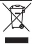
Nur fur EU-Lander
Only for EU countries.
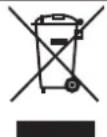
Do not dispose of electric tools together with household waste material! In observance of european directive 2002/96/EC on wasted electrical and electronic equipment and its implementation in accordance with national law, electric tools that have reached the end of their life must be collected separately and returned to an environmentally compatible recycling facility.
France
Grand carton (colls 1/2)
- After unpacking, check all parts for any transport damage. Inform the supplier immediately of any faults.
- Later complaints cannot be considered.
- Make sure the delivery is complete
- Before putting into operation, familiarize yourself with the machine by carefully reading these instructions.
5.Use only original scheppach accessories, wearing or replacement parts. You can find replacement parts at your scheppach dealer. - When ordering, include our item number and the type and year of construction of the machine.
Dear customer,
We wish you much pleasure and success with your new scheppach machine.
NOTE:
In accordance with valid product liability laws, the manufacturer of this device shall not be responsible for damage to and from this device which results from:
- Improper care.
- Noncompliance with the Operating Instructions.
- Repairs made by unauthorized persons.
- The installation and use of any parts which are not original scheppach replacement parts.
- Improper use and application.
- Failure the electrical system as a result of noncom pliance with the legal and applicable electrical directives and VDE regulations 0100, DIN 57113 / VDE 0113.
We recommend that you read through the entire operating instructions before putting into operation.
These operating instructions are to assist you in getting to know your machine and utilize its proper applications.
The operating instructions contain important notes on how you work with the machine safely, expertly, and economically, and how you can avoid hazards, save repair costs, reduce downtime and increase the reliability and service life of the machine.
In addition to the safety requirements contained in these operating instructions, you must be careful to observe your country's applicable regulations.
The operating instructions must always be near the machine. Put them in a plastic folder to protect them from dirt and humidity. They must be read by every operator before beginning work and observed conscientiously. Only persons who have been trained in the use of the machine and have been informed of the various dangers may work with the machine. The required minimum age must be observed.
In addition to the safety requirements contained in these operating instructions and your country's applicable regulations, you should observe the generally recognized technical rules concerning the operation of woodworking machines.
Safety notes

In these operating instructions we have marked the places that have to do with your safety with this
sign.
- Please pass on safety notes and instructions to all those who work on this machine.
- Personnel entrusted with work on the machine have read the operating instructions and in particular the chapter on safety before beginning work. Reading the instructions after work has begun, is too late. This applies especially to persons working only occasionally on the rnachine, e.g. during setting up or rnaintenance.
- Observe all safety instructions and warnings attached to the machine.
See to it that all safty instructions and warnings attached to the machine are complete and perfectly legible. - Check all power supply lines. Do not use lines.
Make sure that the machine stands stable ground.
Insure sufficient lighting in the work area and the area around the machine. - Caution when working: There is a danger to fingers and hands from the rotating tool.
- When working on the machine, all safety mechanisms and covers must be mounted.
- Keep children away from the machine when it is connected to the power supply.
- Operating personal must be at least 18 years of age. Trainees must be at least 16 years of age, but may only operate the machine under adult supervision.
- Persons working on the machine may be not diverted from their work.
- The working space on the machine must be free of chips and wood scrap.
- Wear only close-fitting clothes. Remove rings, bracelets and other jewelry.
Always wear safety goggles when working. - Wear a cap or hair net to protect long hair.
- Wear suitable gloves to change the sawband.
- Do not wear work gloves when working on the saw.
- Observe the correct rotational speed setting on the machine.
- The safety mechanism on the machine may not be removed or rendered unusable.
- Cleaning, changing, calibrating, and setting of the machine may only be carried out when the motor is switched off. Pull the power supply plug and wait for the rotating tool to completely stop.
- Connection and repair work on the electrical installation may be carried out by a qualified electrician only.
- All protection and safety devices must be replaced after completing repair and maintenance procedures.
- Switch the machine off and pull power supply plug when rectifying any malfunctions.
- Use a suction unit to suck up wood shavings and sawdust. The current speed at the suction connection piece should be 20m / s .
- Check the saw band guide and the saw band tension before starting up.
- Do not use nicked saw bands or those that have an altered form.
- Replace table inserts that have worn saw slots.
-
When sawing round wood, make sure that the work piece does not turn.
-
For sawing heavy or cumbersome pieces, use the appropriate working aids for bracing. (Special accessory roller stands).
- Place the upper saw band guide as closely as possible to the work piece.
- On slanted table plates, attach the longitudinal stop on the lower table plate half.
- Do not brake the saw band with side switching off.
- Remove work pieces that have become stuck only with the motor switched off and with the saw band at a standstill.
- Cut off the external power supply of the machine even if only minor changes of place are envisaged. Properly reconnect the machine to the supply mains before recommissioning.
- When leaving the work place, switch the motor off. Pull the power supply plug.
Use only as authorized
CE tested machines meet all valid EC machine guidelines as well as all relevant guidelines for each machine.
All protective and safety device must be mounted on the machine before beginning work.
- The machine is designed to be operated by one person. The operator is responsible for all other persons in the working area.
- Observe all safety instructions and warnings attached to the machine.
See to it that safety instructions and warnings attached to the machine are always complete and perfectly leg- ible.
- The bandsaw with the supplied tools and accessories is designed exclusively for sawing wood, material similar to wood, and non-ferrous metals and steel.
The maximum dimensions for workpieces to essed is may not exceed the bench size in the standard version. Clearance width: 306mm Clearance height: 205mm
- For larger workpiece dimensions which require of the table top, the table extension or the dolly (special accessories) must be used.
- The band saw can also be used for sawing metal when it is equipped with a special saw band dolly (special accessory) and a operated at an adapted cutting speed. Metal allows with more than 80% magnesium may not be processed due to the danger of fires.
- When used in enclosed rooms, the machine connected to a vacuum exhaust unit. Use the dust extractor to remove matchwood or saw dust. The vacuum support flow rate must be 20m / s . Subatmospheric pressure 860 Pa.
The automatic switching unit is available as a special accessory.
Type ALV 2 Art. No.79104010 230 V/50 Hz Type ALV 10 Art.No.79104020 400 V/230 V/50 Hz
The vacuum exhaust unit automatically switches on after a 2-3 second delay after the machine tool is turned on. This avoids overloading the circuit fuse.
After turning off the machine tool, the vacuum exhaust unit remains on for an additional 2-3 seconds and is then automatically switched off. Remaining dust is thereby removed by vacuum exhaust, as required by German regulations governing hazardous materials. This results in savings in electricity consumption and reduces noise
levels, as the vacuum exhaust unit is on only during machine tool operation.
- A suction device which conforms with commercial regulations must be used for suction in commercial areas.
- Do not switch off or remove suction units or dust extractors while the work machine is in operation.
The machine must only be used in technically unconditioned in accordance with its designated use and the instructions set out in the operating manual, and only by safety-conscious persons who are fully aware of the risks involved in operating the machine. Any functional disorders, especially those affecting the safety of the machine, should therefore be rectified immediately. - The safety, work and maintenance instructions manufacturer as well as the technical data given in the calibrations and dimensions must be adhered to.
- Relevant accident prevention regulations and other, generally recognized safety-technical rules must also be adhered to.
- The machine may only be used, maintained, and operated by persons familiar with it and instructed in its operation and procedures. Arbitrary alterations to the machine release the manufacturer from all responsibility for any resulting damages.
The machine may only be used with original accesses and original tools made by the manufacturer. - Any other use exceeds authorization. The manufacturer is not responsible for any damages resulting from unauthorized use; risk is the sole responsibility of the operator.
Remaining hazards
The machine has been built using modern technology in accordance with recognized safety rules. Some remaining hazards, however, may still exist.
- Risk of injury for fingers and hands by the rotating saw band due to improper handling of the work piece.
- Risk of injury through the hurling work piece due to improper handling, such as working without the push stick.
- Risk of damaging your health due to wood dust and wood chips. Wear personal protective cloth such as goggles. Use a fitting dust extractor.
- Risk of injury due to defective saw band. Regularly check saw band for such defects.
- Risk of injury for fingers and hands while changing saw band. Wear proper gloves.
mursk djejury due to starting saw band while switching on the machine.
- The use of incorrect or damaged mains cables can lead to injuries caused by electricity.
- Wear only close-fitting clothes. Remove rings, bracelets and other jewelry.
- For the safety of long hair, wear a cap or hair net.
- Even when all safety measures are taken, some remaining hazards which are not yet evident may still be present.
- Remaining hazards can be minimized by following the instructions in "Safety Precautions", "Proper Use" and in the entire operating manual.
The noise emission values determined according to EN 23746 for the sound level and according to EN 31202 (coefficient of correction k3 calculated according to Appendix A.2 of EN 31204) for the sound level at the workplace are as follows, based on the working conditions listed in ISO 7904 Appendix A:
Sound level in dB
Idle running LWA = 80.3 dB(A)
Operation LWA = 100.2 dB(A)
Sound level at the workplace in dB
Idle running LpAeq = 64.1 dB(A)
Operation LpAeq = 82.9 dB(A)
A measurement uncertainty allowance K = 4 dB applies to the mentioned emission values.
Legendre (Fig. 1)
- Table machine
Prepare the workplace where the machine is to be placed. Insure sufficient room to allow safe work without malfunctions. The machine is designed to operate in closed rooms and must be placed stably on firm level ground. Stability is insured by attachment to the ground with 4 screws.
Transport
The machine may only be lifted and transported at the identified points. Never lift the machine at the safety devices, the adjusting levers, or the sawing table.
During the transport the saw blade protection must be in the lowest position and near the table.
Never raise at the table!
Unplug the machine from the mains during transport.
Mounting
Your bench band saw is delivered in 2 cartons
Supplied Standard Elements
Large Carton (Carton 1/2)
- 1 bench band saw, partly assembled
-1 Machine Table
-1 Support Rail for Rip Fence - 1 Support for Rip Fence
-1 Scale for Rip Fence
-1 Clamping Handle
-1 Sliding Rod
-1 Operating manual
- 1 Bag of Accessories, containing:
-1 Spanner SW10
-1 Spanner SW13
-1 Hexagon Wrench Key SW 2,5
- 1 Hexagon Wrench Key SW 3
- 1 Hexagon Wrench Key SW 4
-1 Hexagon Wrench Key SW 5
- 1 Hexagon Wrench Key SW 6
- 1 Set of Screws for the assembly and installation of the machine
-3 Table Insert(s)
Small Carton (Carton 2/2)
-2 Legs
-2 Wheels
- 1 Bracket for Transport Lever
-1 Transport Lever
- 1 Set of Screws for Assembly of the Base Frame
Preparation for the Assembly of the Machine
- Take the standard elements out of the large carton. Fig. 3
- Use the polystyrene packaging as support during the machine assembly. Fig. 4
- Remove the standard elements from the small carton.
Installation of the Bracket for the Transport Lever Fig. 5
- Remove rear side in order to get access to the inside of the edifice.
- Fasten the Transport Lever with 2 screws M8x20 and 2 nuts M8.
- Reattach the rear side.
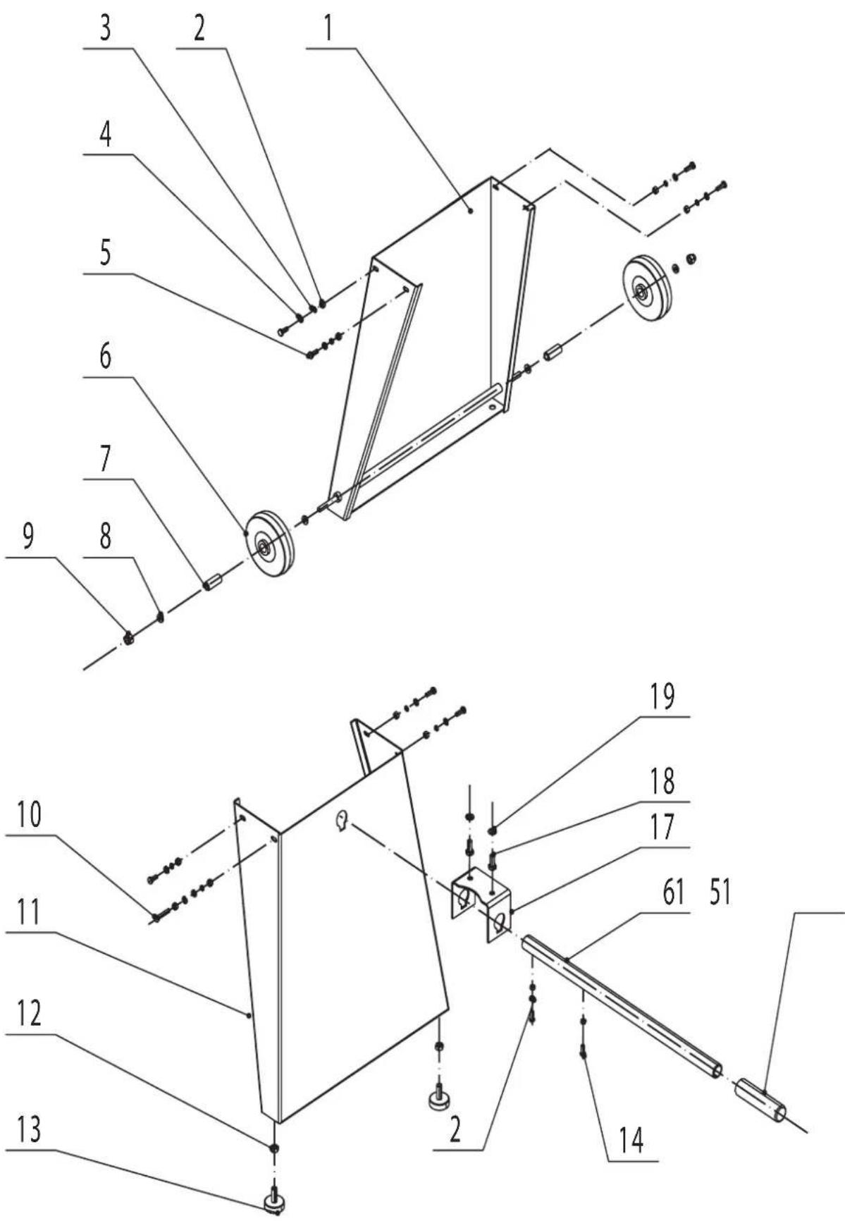
Assembly of the Base Frame - Fig. 6
Attach the wheels to the foot (with the welded-on axis).
Mounting the Wheels (see more details in Fig. 6a):
- Place a M8 washer on the axis,
- Attach the wheel,
- Place another M8 washer on the axis
Finish installation with a self-locking hexagon nut M8
Fastening the 2 legs under the band saw - Fig. 7
Attention:
- The leg with the 2 wheels must be mounted on the side of the motor.
Attach the leg to the machine using 4 screws M6x16 + washers M6 + spring washer M6 + nut M6.
- The leg with the round buffers and the hole for the transport lever must be mounted on the side where the extraction connection is located
. Fasten the leg to the machine with 3 screws M6x16 + washers M6 + spring washer M6 + nut M6.4.
A 4th, longer screw, M6x30 is to be used on the front side of the machine: it serves as support of the leg, as well as hook for the sliding rod so that the latter is easily accessible.
Put the machine in upright position.
You can do this alone, however, due to the weight and the size of the machine, we recommend you get someone to help you.
Installation of the transport lever Fig. 9 and Fig. 9a
- Remove screw, nut and counternut.
- Pass the transport lever through the holes in the leg and the
bracket.
- Attach screw, nut and counternut to the lever.
Installation of the electric switch Fig. 10
Fasten the electric switch to the machine housing using 4 screws M4x60
Installation of the table top (1), Fig. 11 and Fig.12
- Prepare table top: Remove the connection screw on the front edge of the table. If required, remove oil or grease.
The bench band saw is supplied with the panning segment (8) being adjusted to 45^ . - Release the handle A with the handle B, bring the panning segment into the 0^ position.
- Place the table top on the machine (Attention: table top weighs 16 kg).
- Fasten the table top with 4 M8x20 + washer M8 + spring washer M8.
- Tighten the screws.
- Re-attach the connection screw on the front edge of the table.
Adjustment of the table top (1), Fig. 14
- Set the table top to position 0^ (see angle scale on the pivoting segment).
Place a flat square on the table plate. Check the angle (90^) between table plate and the band saw blade.
If the angle is not 90^ - Unfasten the handle A.
- Adjust the horizontal of the table plate using the handle B until it reaches 90^ .
- Set the adjusting screw: this screw is used as limit stop in order to always reach the position of 90^ quickly and precisely.
- If the angle display C is not on «zero», unfasten the crosshead screw, adjust the angle display by using a Phillips head screw driver.
If C angles indicator in not pointed towards «Zero», readjust it by loosening cross-shaped head screw.
Table light, Fig. 1 indicator 1a
Table is equipped with an opening to allow the blade of a power saw to go through.
To prevent any contact between the power saw blade (steel) and the machine bench (cast iron), a light plastic table is inserted through the table opening: this is a part that needs to be replaced on a regular basis.
Parallel guide assembly
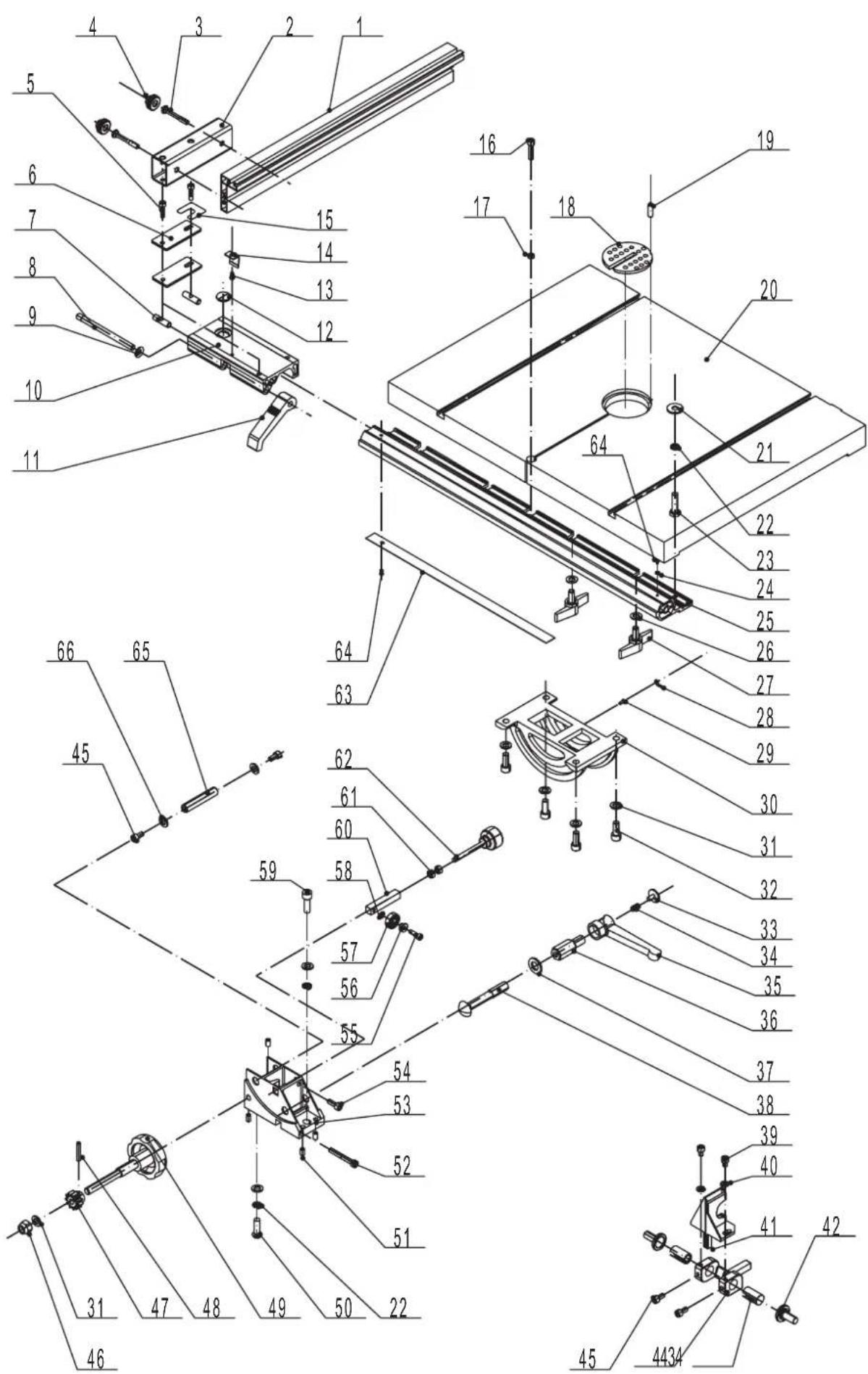
Fastening of support railing (2), Fig.15 and Fig. 15a
Affix the parallel guide of support railing to the front end of the machine bench using M8x20 screw + M8 washer.
Tighten screw so that support railing may move without any give.
Support railing must remain flexible to allow for access when it is time to change the power saw blade.
Position the two M8x18 butterfly screws + M8 washer in the threaded holes designed to that effect, under the machine bench.
Put in place support railing, until it comes in contact with the edge of the machine bench. Completely tighten the 2 butterfly screws.
Parallel guide assembly, Fig. 16
Parallel guide is comprised of:
-
1 parallel guide fastening support (2a)
-
1 parallel guide delineating ruler (2b)
Assemble the 2 elements
Parallel guide adjustment, Fig. 17
Position parallel guide on support railing (2). Parallel guide must now be parallel to the slot on the table. If that is not the case, it is possible to adjust the positioning by loosening the two cylindrical head screws of the fastening support (2a) of the parallel guide, adjusting the parallelism, and retightening the 2 screws.
Graded ruler adjustment, Fig. 18 and Fig. 18a
Position parallel guide so that delineating ruler lightly rubs against the teeth of the power saw blade.
Look through a magnifying lens to ascertain that vertical line is on position 0
If necessary, re-adjust graded ruler by loosening the 2 cross-shaped head screws of the graded ruler, then move graded ruler so that the 0 becomes aligned with the vertical line of the magnifying lens.
Re-tighten the 2 cross-shaped head screws.
Transport, Fig. 19
To move the power saw, pull the transport handle (6b) towards you, tilt machine forward until the transport wheels are in contact with the ground, then move the machine by slightly lifting it, using the transport handle.
Once you reach the location where you want to put the machine, put it on the ground then reset the transport handle.
Attention: Before starting to use the power saw, it must be once again set on the ground, in a stable manner. If necessary, level up the machine by adjusting rubber supports located under the machine (Fig.20)
Putting into operation
Adhere to safety measures before putting into operation.
All safety and protection devices have to be in place for the job.
Replacing saw blade (13)
At the time of delivery of Band saw, the saw blade is mounted on the machine. You must however verify that blade is properly adjusted.
Attention: To change or adjust blade, unplug machine from power socket!
Blade-guides with hooks
In order to work in full safety and great accuracy, power saw blade is guided by:
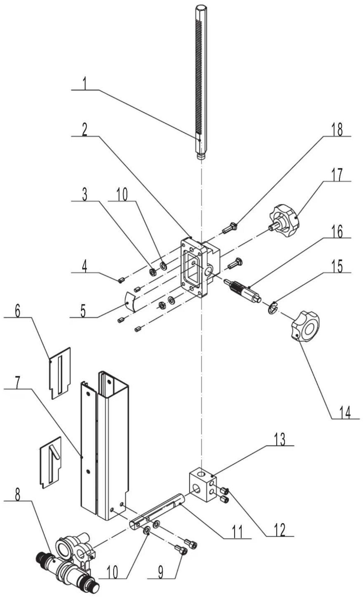
- a blade-guide at the top level, called top blade-guide, Fig. 1 (7), Fig. 21 and Fig. 21a
Top blade-guide is attached to a dial. It can be adjusted for a cutting piece of up to 200mm in hight. The smallest possible distance, between top blade-guide and part to be cut ensures optimal guiding of the blade, as well as working with maximum safety!
Composition of the top blade-guide:
- 1 left lateral hook mounted on micrometric screw
- 1 right lateral hook mounted on micrometric screw
-
1 rear hook mounted on axle
-
a blade-guide with hooks at the bottom level, called bottom blade-guide, Fig. 1 (7a), Fig. 22
Bottom blade-guide is affixed to machine bottom
Composition:
- 1 left lateral hook mounted on axle
- 1 right lateral hook mounted on axle
- 1 rear hook mounted on axle
Replacing saw blade
Dis-assembly of saw blade
Unplug machine from power socket.
Separate lateral hooks and rear hooks of the top and bottom blade-guides
Open door (4) of the power saw
Remove binding screw located on the front edge of the machine bench (1)
Tilt the support of parallel guide (2)
Turn handle(3) and tilt lever (3a) to the right to loosen up blade of the power saw.
Remove blade from power saw (13)
Assembly of power saw blade
Mount new blade of power saw (13) on the to and bottom spans.
Attention: ensure that the teeth of the power saw blade are to the right orientation, meaning teeth towards the bottom side of the blade-guides.
Blade tension
Pre-tension power saw blade by tilting lever (3a) to the left.
Turn spans (9) et (10) by hand in the cutting direction (meaning clockwise) and at the same time turn handle (3) to tighten blade. Tension depends on the width of the power saw blade. Use tension indicator to help put blade under right tension (3c).
Attention: If blade tension is too high, this could cause premature rupturing of power saw blade!
Positioning of the blade
To position saw blade on the spans, manually turn spans of the cutting direction (meaning clockwise) and at the same time turn handle (3b). This handle facilitates the advancement and retracting of the spans. When saw blade is correctly positioned, block the counter-screw located under the handle (3b).
The advancement of the power saw blade teeth must be identical on the 2 spans. It is recommended to extend the teeth of the blade away from the mouldings of the spans.
Adjustment of the top (7) and bottom (7a) blade-guides
This adjustment must be made when the blade is properly positioned on the spans and at a good tension.
- Adjust top and bottom lateral hooks as equality apart as possible from both sides of the power saw blade.
Blade may not be blocked!
Attention: lateral hooks must not enter in contact with the teeth of the saw blade. If this would happen, power saw blade runs the risk of deteriorating.
- Rear, top and bottom hooks absorb the pushing action produced by the piece to be sawed.
Position rear, top and bottom hooks so that they turn while lightly resting on the blade.
IMPORTANT:
Once you have finished your work with the power saw, blade must always be released! Do this by tilting lever (3a) on the right.
Put a label on the machine to indicate that the power saw blade has been relaxed!
Utilisation of the parallel guide
Positioning of the counter-guide, in relation to the width of the pieces to be sawed.
- Position 1 (Fig. 23): For the sawing of wide and thick pieces. The width of indicated cut is located on the top indicating scale.
- Position 2 (Fig. 24): For the sawing of narrow and thin pieces. The width of indicated cut is located on the bottom indicating scale
Pushing device (12)
You must use the pushing device for longitudinal cutting of narrow pieces (under 100mm ).
Informations regarding labels pasted on to the power saw, Fig, 25
Attentively read notification delivered with power saw, before operating machine
II) «Blade Tension» label:
Serves as an indicator for the blade tension.
- If lever (3a) is to the left, blade is under tension.
- If lever (3a) is to the right, blade is relaxed.
III) Blade Positioning label
Informs as to position saw blade on the spans:
- By turning handle (3b) to the left, saw blade «exits» towards the front edge of the spans,
- By turning handle (3b) to the right, saw blade «enters» towards the back edge of the spans.
IV) «Blade Tension Indicator» label
Informs of blade tension, in relation to the width of the blade. Example: if the saw blade is 16mm wide, indicator must be on the plane labeled 16 .Blade tension is then correct!
V) «Belt» label
Informs of the type and dimensions of the belt that comes with the power saw.
VI) «Engine» label
Informs of the technical characteristics of the engine that comes with the power saw.
VII) «Machine» label
Informs of the characteristics of the machine.
IMPORTANT:
To order accessories, spare parts, or during maintenance or repairs, you must supply the following information :
- Reference number of the machine (Example: Ref. 1901502901)
- Year of manufacture (Example: Yr. 2013)
- Serial number (Example: 1001)
Working information:
The following recommendations are examples of the safe use of band saws.
The following safe working methods should be seen as an aid to safety. They cannot be applied suitably completely or comprehensively to every use. They cannot treat every possible dangerous condition and must be interpreted care
fully.
- Connect the machine to a suction unit when working in closed rooms. A suction device which conforms with commercial regulations must be used for suction in commercial areas.
- Loosen the sawband when the machine is not in operation (e.g. after finishing work). Attach a notice on the tension of the saw band to the machine for the next user.
- Collect unused sawbands and store them safely in a dry place. Check for faults (teeth, cracks) before use. Do not use faulty sawbands!
- Wear suitable gloves when handling sawbands.
- All protective and safety devices must be securely mounted on the machine before beginning work.
- Never clean the sawband or the sawband guide with hand-held brush or scraper while the sawband is running. Resin-covered sawbands impair working safety and must be cleaned regularly.
- For your own protection, wear protective glasses hearing protection. Wear a hairnet if you have long hair. Roll up loose sleeves over the elbows.
Always position the sawband guide as near the workpiece as possible when working. - Insure sufficient lighting in the work area and around the machine.
Always use the fence for straight cuts to keep the workpiece from tipping or slipping away. - When working on narrow workpieces with manual feed, use the push stick.
- For diagonal cuts, place the saw bench in the appropriate position and guide the workpiece on the fence.
- To cut dove-tails and dove-tailed tenons or wedges swing the saw bench to the plus or minus position. Insure safe workpiece guidance.
- For arced and irregular cuts, push the workpiece evenly using both hands with the fingers together. Hold the workpiece with your hands on a safe area.
- Use a pattern for repeated arced or irregular cuts.
- Insure that the workpiece does not roll when round pieces.
- Use the traverse cutting gauge special accessory for safety when making traverse cuts.
- To safely cut round plates, use the circular cutting unit special accessory.
m = 311
cutting
Electrical Connection

The installed electric motor is connected and is ready to work.
The connection complies with the relevant VDE and DIN regulations.
The customer-side mains supply and the used extension line must meet these regulations.
Installations, repair, and maintenance work relating to the electric installation may only be performed by specialists.
Important Notes
The electric motor has been designed for the S 1 operating mode.
In case of an overload of the motor, it turns off automatically. After a cooling period (duration varies), you can turn on the motor again.

Defective Electric Connection Lines
Often, insulation damages occur on electrical connection lines.
Causes are:
- Drag marks if connection lines are led through window or door clearances.
- Kinks due to improper attachment or routing of the connection line.
- Cuts caused by running over the connection line.
- Insulation damages caused by pulling the connection line out of the wall socket.
- Fissures caused by the ageing of the insulation.
Such defective electric connection lines must not be used and are hazardous due to the insulation damages.
Regularly check the electrical connection lines for damages. Please make sure that the connection lines are disconnected from the mains supply during the check.
Electrical connection lines must comply with the relevant VDE and DIN regulations. Only use connection lines labelled with H 07 RN. The labelling of the connection cable with the type specification is required.
AC motor
- The supply voltage must be 230V / 50Hz
- Extension lines up to a length of 25m must have a cross section of 1.5 square millimetres. Extension lines with a length of more than 25m must have a minimum cross section of 2.5 square millimetres.
- The mains connection is protected with a delay-action fuse of 16 A.
Rotary current motor
- The supply voltage must be 400V / 50Hz
- Mains supply and extension line must be five-wire = 3P + +
- Extension lines must have a minimum cross section of 1.5 square millimetres.
- The mains connection is protected with a maximum of 16 A.
- In case of mains supply or change of location, the direction of rotation must be checked. If required, the polarity must be reversed.
If you have further questions, please specify the following:
- Motor manufacturer
- Kind of current of the motor
-
Data from the machine type plate
-
Data from the switch type plate
If you return the motor, always return the complete drive unit with the switch.
Maintenance
Perform resetting, measuring, and cleaning work exclusively when the motor is turned off. Disconnect the mains plug, and wait until the rotating tool stands still.
All protection and safety devices must be immediately reinstalled once the repair and maintenance work is completed.
The built-in ball bearings are maintenance-free.
Recommendations:
- Slightly re-lubricate the slewing segments of the table and the bend tensioning device.
- Regularly clean the saw band. Wood leaves resin sediments.
- Regularly check the guiding rollers and the counterpressure bearings. If required, readjust or disassemble them, and grease or exchange the parts.
- Exchange worn-out table inserts.
- Ensure that the tabletop is always free of resin.
| Trouble shooting | |||
| Fault Possible cause Solution | |||
| Motor does not start a) | No powerb) Switch, Condenserc) Electrical extension cord is defective | a) Check mains connectionb) Have them checked by an electrical engineerc) Remove the plug from the socket, check it, and replace if necessary | |
| Saw blade is not running straight | a) Guide has been wrongly setb) Wrong saw blade | a) Set the saw blade guide according to the operating instructionsb) Select a saw blade according to the operating instructions | |
| Burn marks appear on the wood during the cutting work | a) Blunt saw bladeb) Wrong saw blade | a) Change the saw bladeb) Select a saw blade according to the operating instructions | |
| Saw blade jams during cutting work | a) Blunt saw bladeb) Deposits on the saw bladec) Guide has been set poorly | a) Change the saw bladeb) Clean the saw bladec) Set the saw blade guide according to the operating instructions | |
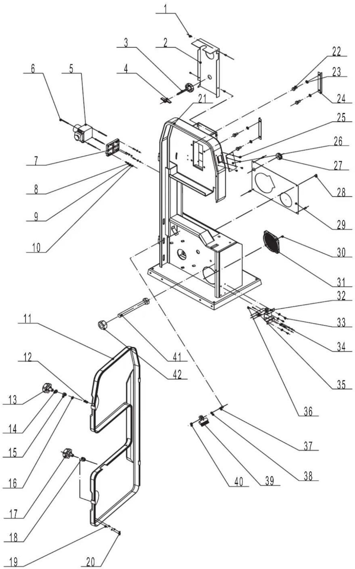
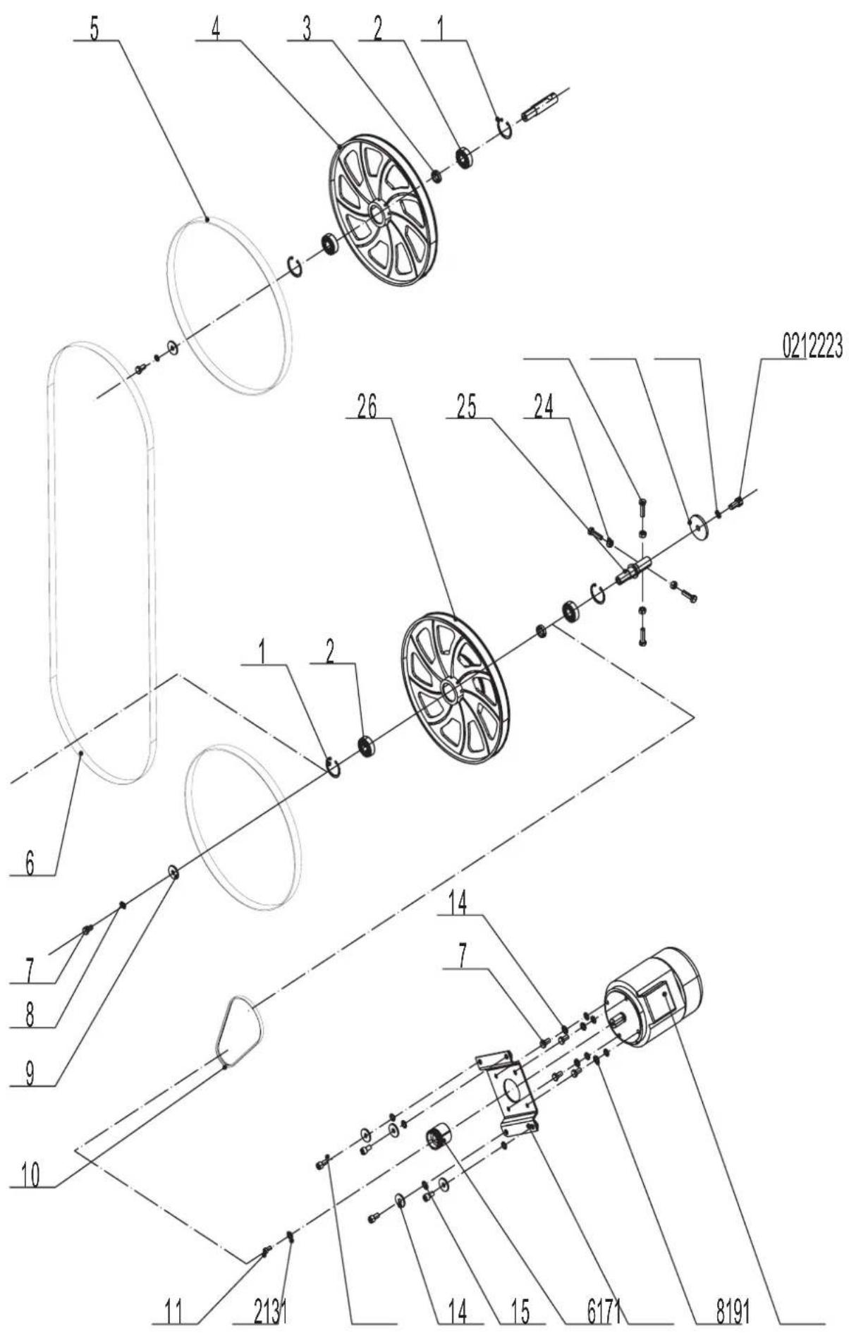
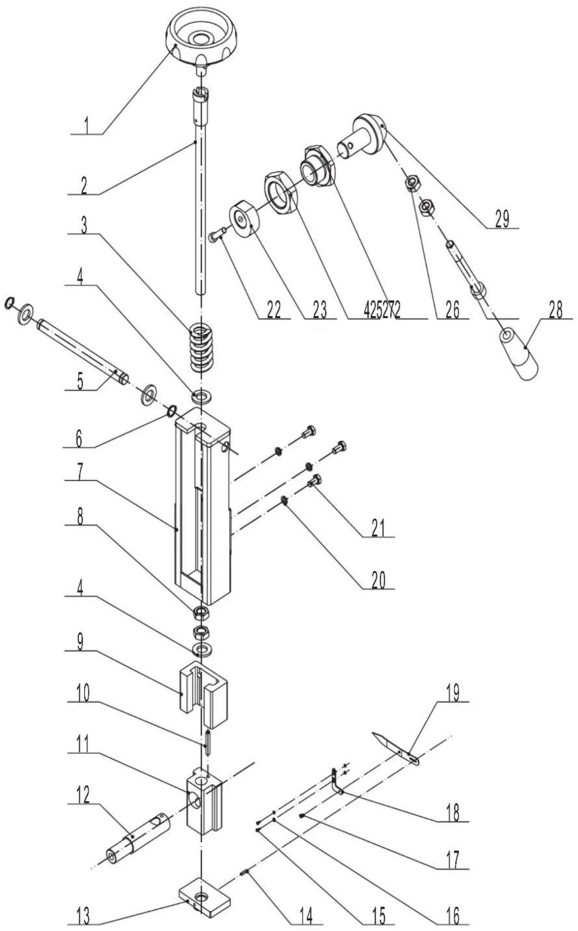

| scheppach Fabrikation von Holzbearbeitungsmaschinen GmbH • Günzburger Str. 69 • D-89335 Ichenhausen | ||
| Konformitätserklärung CE | ||
| DE | erklart folgende Konformität gemäß EU-Rich-line und Normen für den Anteil | SK prehlasujne nasledujúcu zhodu podla smernice EU a noriem pre výrobok |
| GB | hereby declares the following conformity under the EU Directive and standards for the following article | EST kinnitab järgmist vastavus vastavalt ELi direk-tiivi ja standardite järgmist articlinumbrit |
| FR | déclare la conformité suivante selon la directive UE et les normes pour l'article | LT pareiszkia, taip atitiktis pagal ES direktyvos ir standartai ši straipsnj |
| IT | dichiara la seguente conformità seconde le dirittive e le normative UE per l'articolo | LV apiecina šādu saskañar ar ES direktivu atbilstibas un standarti šādu rakstu |
| CZ | prohlasujne následujíci shodu podle smernice EU a normem pro výrobek | NL verklaart hierbij dat het volgende artikel voldoet aan deaarop betrekking hebende EG-richtl-jnen en normen |
| HU | az EU-irányel és a vonatkoźó szabványok szer-inti következo megfeleloségi nyilatkozatot teszi a termékre | RUS заюнет о COOTBETCTBIM TOBAPA sleduуоим dinpektivam и hopmam EC |
| HR | ovime izjavljuje da postoji sukladnost prema EU-smjernica i normama za slijedce artikle | PT declara o segunte conformidade com a Direc-tiva da UE e as normas para o segunte artigo |
| RO | declara urmátoarea conformitate corespunzátör directivelor ši normelor UE pentru articolul | ES declara la conformidad sugiente según la direc-tiva la UE y las normas para el articulo |
| TR | Normlari geregence asagidaki uygunluk acıkla masini sunar. | DK erkrær hermed, at følgende produit er over-ensstemmelse med nedenstände EUdirektiver og standarder: |
| FIN | vakuutta täten, että seuraava tuote tãytãä ala esitetyt EU-direktiivit ja standardit | SE fösakrar härmed fällande överensstämelse entligt EU-direktiv och standarder für fällende articeln |
| PL | declaruje, ze produkt jest zgodny z nastepuja-cymi dyrektywami UE i normami | NO erkrær herved følgende samsvar under EU-direktiv og standarder for følgende artikel |
| SLO | izjavla slezdeco skladnost z EU-direktivo in nor-mami za artikel | |
| Bandsäge - Basa 3.0 | ||
| 2009/105/EC | 89/686/EC_96/58/EC | |
| X 2006/95/EC | X 2006/42/EC | |
| 2006/28/EC | Annex IV Notified Body: Prüf- und Zertifizierungsstelle Holz im DGUV-Test Volmlöllerstraße 11, 70563 Stuttgart Notified Body No.: 0392 | |
| 2005/32/EC | ||
| X 2004/108/EC | 2000/14/EC_2005/88/EC | |
| 2004/22/EC | Annex V Annex VI Noise: measured LVA = xx dB(A); guaranteed LVA = xx dB(A) Notified Body: Notified Body No.: | |
| 1999/5/EC | ||
| 97/23/EC | ||
| 90/396/EC | 2004/26/EC | |
| X 2011/65/EU | Emission. No: | |
| Standard references: EN 12100; EN 13857; EN 349; EN 13850, EN 847-1; EN 13849-1; EN 1088; EN 1807-1; EN 60204-1; EN 60555-2; EN 60555-3 | ||
| Ichenhausen, den 12.03.2013 | H. B. M. | |
Garantle D
Apparent defects must be notified within 8 days from the receipt of the goods. Otherwise, the buyer's rights of claim due to such defects are invalidated. We guarantee for our machines in case of proper treatment for the time of the statutory warranty period from delivery in such a way that we replace any machine part free of charge which provably becomes unusable due to faulty material or defects of fabrica
tion within such period of time. With respect to parts not manufactured by us we only warrant insofar as we are entitled to warranty claims against the upstream suppliers. The costs for the installation of the new parts shall be borne by the buyer. The cancellation of sale or the reduction of purchase price as well as any other claims for damages shall be excluded.