1050265 - Outdoor fire burner Vevor - Free user manual and instructions
Find the device manual for free 1050265 Vevor in PDF.

| Product Type | Outdoor Fire Burner |
| Brand | Vevor |
| Model | 1050265 (compatible with models 1050262, 1050263, 1050264, 1050266, 1050267) |
| Usage | Outdoor only |
| Fuel | Natural gas or LPG (propane) |
| Recommended Gas Pressure (LPG) | 7 to 11 in WC (0.25 to 0.4 psi) |
| Burner Material | Stainless steel |
| Included Components | Burner, fire pan, 4.4 ft regulator hose, 4 ft connection hose, 1/2" shut-off valve, 1/2" air mixer, adapters, connectors, chrome valve, mounting plate |
| Ignition | Manual (match or lighter) |
| Safety Clearances | 36 in minimum on all sides, 8 ft above burner |
| Required Ventilation (LPG) | 20 in² minimum at lowest point of enclosed space |
| Recommended Refractory Glass Depth | 1 to 2 in above burner |
| Maintenance | Inspect before each use, annual cleaning by qualified technician, check for leaks with soapy water |
| Safety | Do not use indoors, risk of carbon monoxide; do not leave unattended; do not use in rain; turn off gas if odor is detected |
| Warranty | Technical support and electronic warranty certificate at www.vevor.com/support |
Frequently Asked Questions - 1050265 Vevor
User questions about 1050265 Vevor
0 question about this device. Answer the ones you know or ask your own.
Ask a new question about this device
Download the instructions for your Outdoor fire burner in PDF format for free! Find your manual 1050265 - Vevor and take your electronic device back in hand. On this page are published all the documents necessary for the use of your device. 1050265 by Vevor.
USER MANUAL 1050265 Vevor
Technical Support and E-Warranty Certificate
www.vevor.com/support
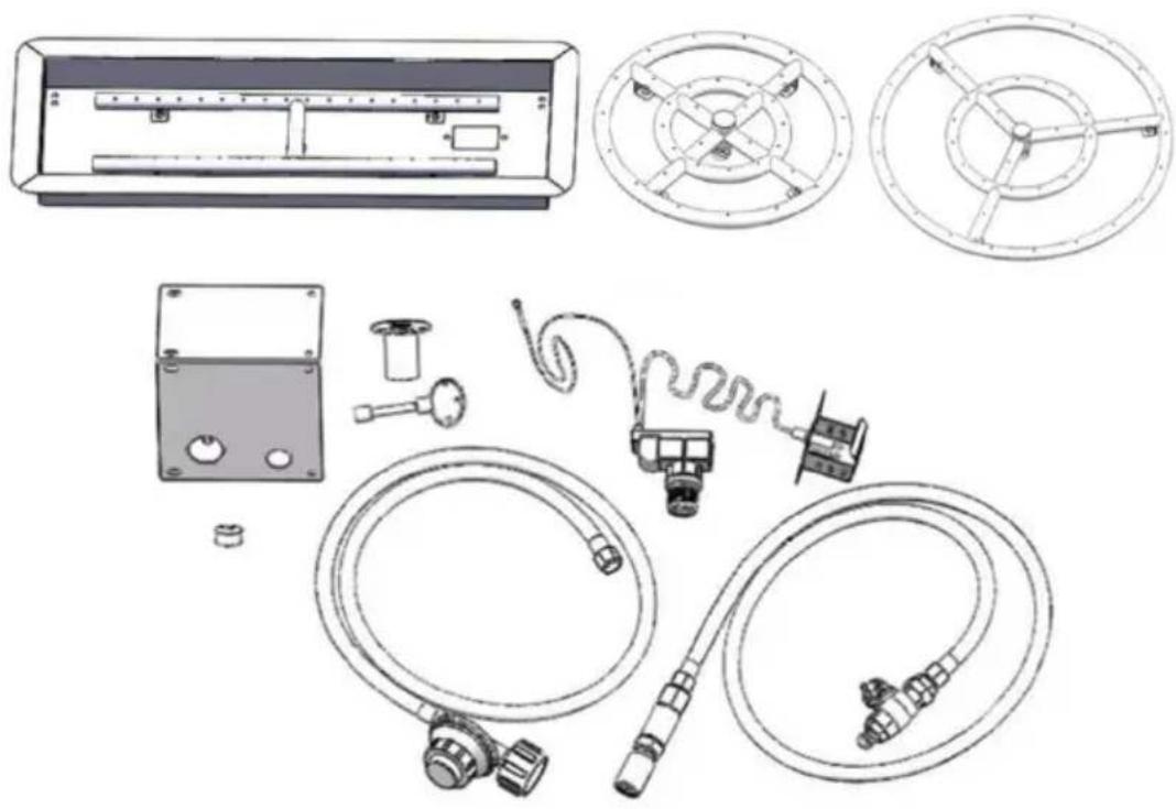
FIRE PIT BURNER/PAN
MODEL:1050262,1050263,1050264,1050266,1050267
We continue to be committed to provide you tools with competitive price. "Save Half", "Half Price" or any other similar expressions used by us only represer estimate of savings you might benefit from buying certain tools with us compared to top brands and does not necessarily mean to cover all categories of tools offered by are kindly reminded to verify carefully when you are placing an order with us if yo actually saving half in comparison with the top major brands.
VEVOR®
TOUGH TOOLS, HALF PRICE
FIRE PIT BURNER/PAN
MODEL:1050262,1050263,1050264,1050266,1050267
natural_image
Technical line drawings of various mechanical and electrical components, including a control panel, gauges, and hoses (no text or labels)NEED HELP? CONTACT US!
Have product questions? Need technical support? Please feel free contact us:

CustomerService@vevor.com
This is the original instruction, please read all manual instructions carefully before operating. VEVOR reserves a clear interpretation of user manual. The appearance of the product shall be subject to the product you received. Please forgive us that we won't inform you there are any technology or software updates on our product.
INSTALLATION PRECAUTION
PLEASE RETAIN THIS MANUAL FOR FUTURE REFERENCE

Warning: For Outdoor Use Only
DANGER
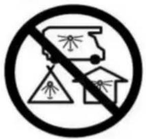
CARBON MONOXIDE HAZZARD
This appliance can produce carbon mono which has no odor.
Using it in an enclosed space can kill y Never use this appliance in an enclosed space.such as a camper, tent, car or ho
DANGER
If you smell gas:
-
Shut off gas to the appliance.
-
Extinguish any open flame
-
If odor continues, keep a from the appliance and immediately call your gas supplier or fire department.

WARNING
Improper installation, adjustment, alteration, service or maintenance can cause injury or property damage.
Read the installation, operating and maintenance instructions thoroughly before installing or servicing this equipment.
WARNING
Do not store or use gasolin other flammable vapors and liquids in the vicinity of this other appliance.
An LP-cylinder not connected for use shall not be stored the vicinity of this or any appliance.
WARNING
Do not leave unattended during use. Do not use for cooking.
Follow all gas leak procedur in this manual before operation.
WARNING: If the information in these instructions is not follo exactly, a fire or explosion may result causing property dama personal injury or death.
INSTALLATION AND OPERATION SAFETY
GUIDELINES
CAUTION: It is NOT recommended outdoor fire features be operated when the wind exceeds 25 mph. Before turning the appliance on, visually inspect the fire feature to ensure debris such as leaves or other combustible material has not inside the element, which could bum and embers once the fire feature is turned. Also, provide any person standing close to the fire feature is aware you will be turning the fire feature on before actually turning it on.
Installation and repair should be done by a qualified service person. The appliance should be inspected before use and at least annual by a qualified service person. More frequent cleaning may be required as necessary. It is imperative that control compartment, burners and circulating air passageways of the appliance be kept clean.
- Do NOT install damaged components.
- Do NOT install incomplete components.
- Do NOT install substitute components.
Ensure the appliance is installed so the vent opening at the unit's base remains obstacle-free at all times and during all weather conditions.
Due to high temperatures, the unit must be located out of traffic areas a away from combustibles.
Children and adults should be alerted to the hazard of high surface temperatures and should stay away to avoid burns or clothing ignition.
Young children MUST be carefully supervised when they are in the area this appliance.
Clothing or other flammable materials should not be hung from the appliance or placed on or near the appliance.
WARNING: HOT WHILE IN OPERATION AND FOLLOWING OPERATION. Serious injury can occur!
DO NOT leave in operation when unattended.
WARNING: DO NOT operate this appliance in the rain.
SOLID FUEL MUST NOT BE BURNED in the appliance.
DO NOT continue using if you smell unusual odors, or have headaches, nausea, or dizziness.
DO NOT store any combustible materials, gasoline, and any other flammable vapors/liquids in the vicinity of the unit. Provide adequate clearance for servicing and operation.
DO NOT throw matches, paper, garbage, or any other material onto the appliance or flame.
DO NOT use the appliance if any part has been underwater. Immediately call a qualified professional service technician to inspect the appliance and to replace any part of the control system and any gas control that has be underwater.
Inspect the fuel supply connection before each use of the appliance.
Temporary storage of this appliance indoors is permissible only if it has been disconnected from its fuel supply (Natural or L.P. gas line).
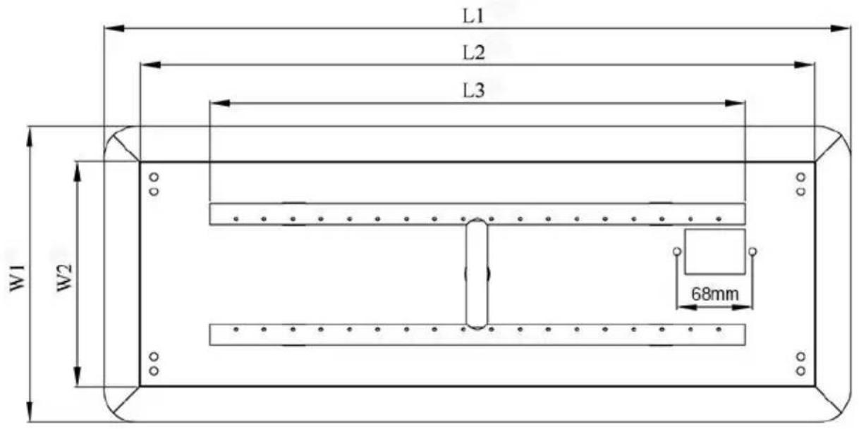
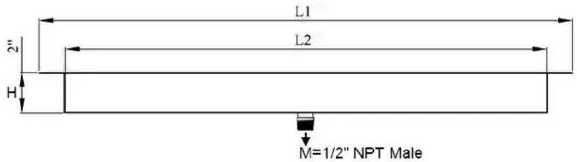
SPECIFICATIONS
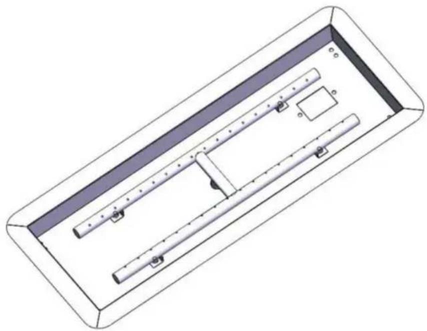
Parameter table- Model#1050262 1050263 1050264
| Model# | Installation Size | L1 | L2 | L3 | W1 | W2 |
| 1050262 | 24"x8" | 26 1/2" | 24" | 19" | 10 1/2" | 8" |
| 1050263 | 30"x10" | 32 1/2" | 30" | 25" | 12 1/2" | 10" |
| 1050264 | 36"x12" | 38 1/2" | 36" | 31" | 14 1/2" | 12" |
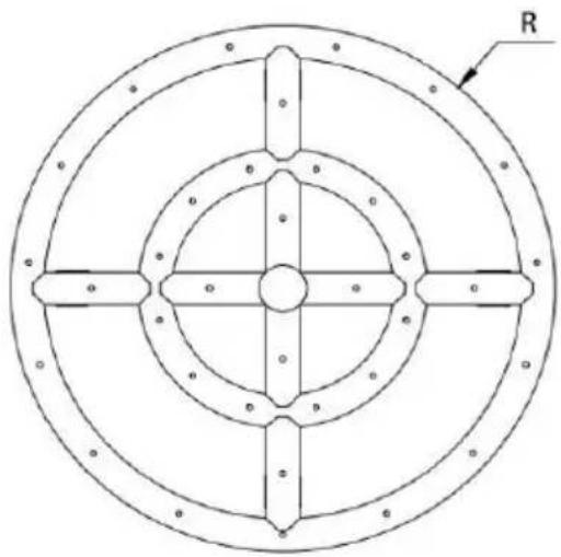
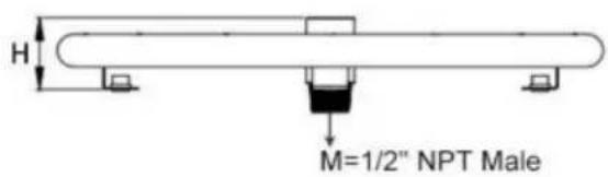
natural_image
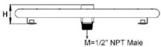
3D technical illustration of a rectangular electronic component with internal channels and mounting holes (no text or symbols)Parameter Table- Model#1050266 1050267
| Model# | Installation Size | R | H |
| 1050266 | 12" | 12" | 1 16/25" |
| 1050267 | 18" | 18" | 1 16/25" |
natural_image
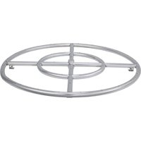
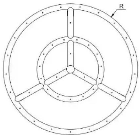
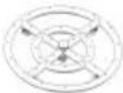
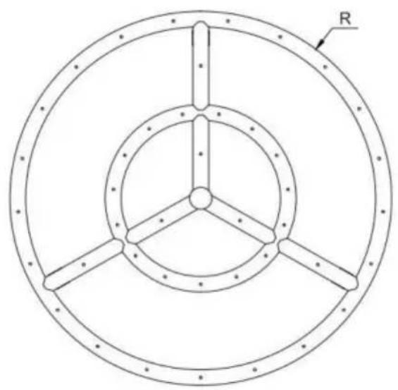
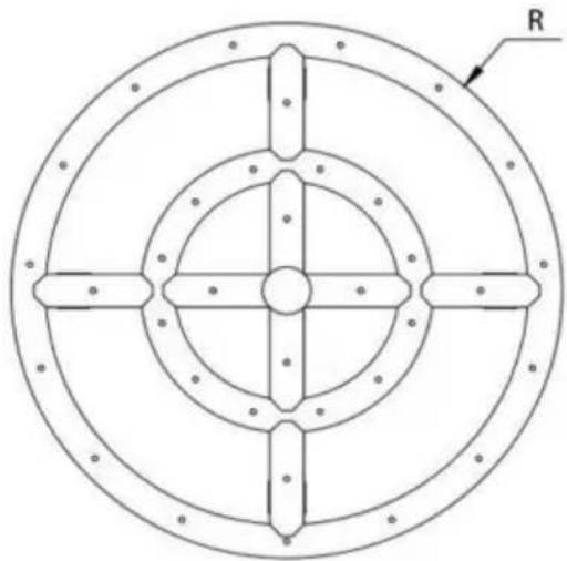
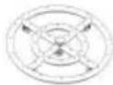
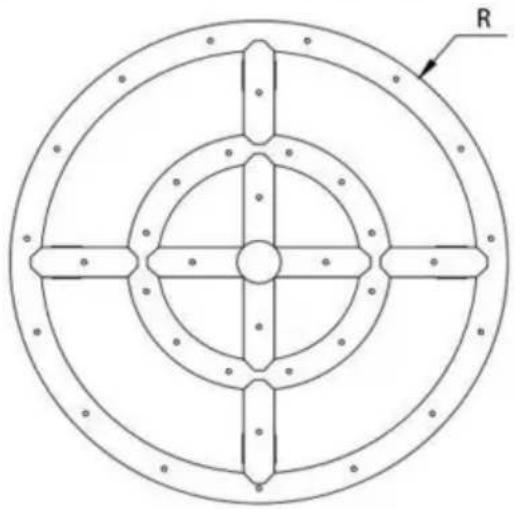
Technical diagram of a circular mechanical component with four symmetrical arms and bolt holes, labeled 'R' in the top right corner (no text or symbols within the diagram itself)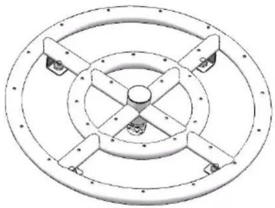
natural_image
Technical line drawing of a circular mechanical component with four symmetrical arms and central hub (no text or symbols)Model#: 1050266
natural_image
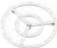
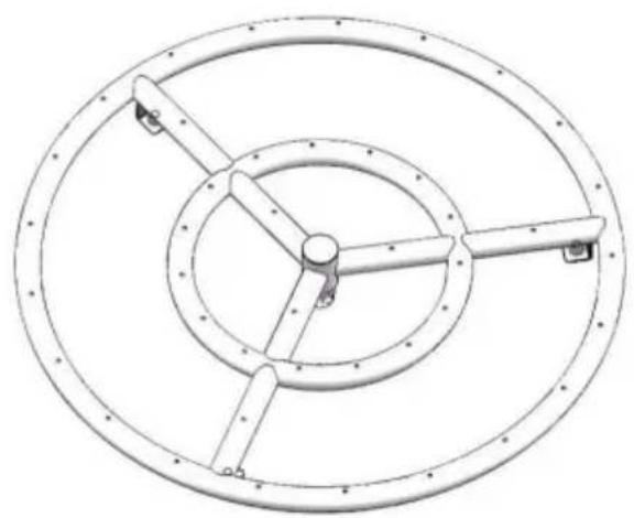
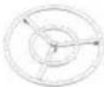
Technical diagram of a circular mechanical component with three concentric rings and radial slots, labeled 'R' (no text or symbols beyond label)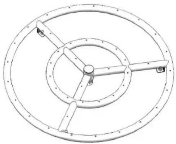
natural_image
Technical line drawing of a circular mechanical component with radial arms and central hub (no text or symbols)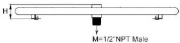
Model#: 1050267
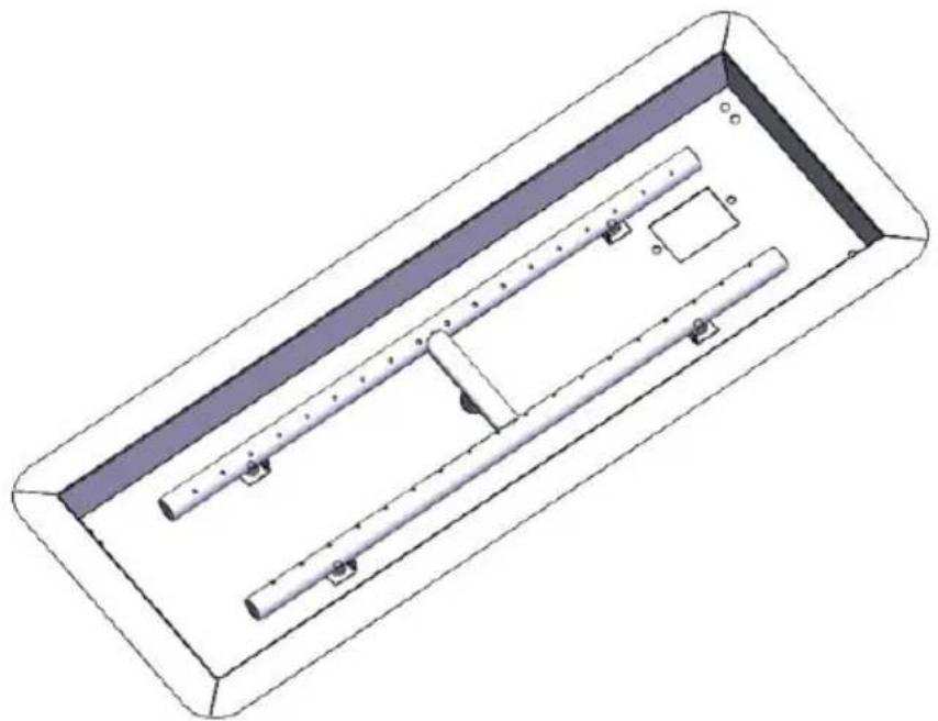
PACKAGE INCLUDE
| No | Components | Q'ty | Picture | Fits Model# | ||||
| 1050262 | 1050263 | 1050264 | 1050266 | 1050267 | ||||
| 1 | Fire Pit Burner | 1 | 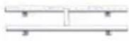 | Y | Y | Y | / | / |
 | / | / | / | Y | / | |||
 | / | / | / | / | Y | |||
| 2 | Fire Pit Pan | 1 | 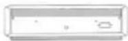 | Y | Y | Y | / | / |
| 3 | 4.4ft Propane Regulator Hose | 1 | 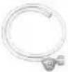 | Y | Y | Y | Y | Y |
| 4 | 4ft Connect Hose | 1 | 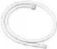 | Y | Y | Y | Y | Y |
| 5 | 1/2" Shut-off Ball Valve | 1 | 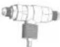 | Y | Y | Y | Y | Y |
| 6 | 1/2" Air Mixer Valve | 1 | 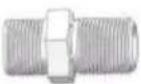 | Y | Y | Y | Y | Y |
| 7 | 1/2" Brass Adapter | 1 | 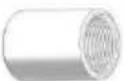 | Y | Y | Y | Y | Y |
| 8 | 1/2" SS Connector | 1 | 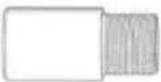 | Y | Y | Y | Y | Y |
| 9 | 5/8-18UNF Brass Connector | 1 | 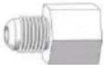 | Y | Y | Y | Y | Y |
| 10 | 1/4 Chrome Qtr-Turn Key Valve | 1 | 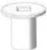 | Y | Y | Y | Y | Y |
| 11 | 3"Chrome Valve Key | 1 | 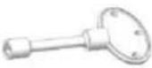 | Y | Y | Y | Y | Y |
| 12 | SS Mounting Plate | 1 | 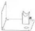 | Y | Y | Y | Y | Y |
| 13 | Spark Ignitor | 1 | 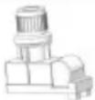 | Y | Y | Y | Y | Y |
| 14 | Lgnition box | 1 | 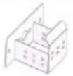 | Y | Y | Y | / | / |
| 15 | Spark Ignitor wire | 1 | 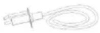 | Y | Y | Y | Y | Y |
| 16 | Ground wire | 1 | 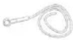 | Y | Y | Y | Y | Y |
| 17 | Removable mounting plate for optional spark Ignitor | 1 | 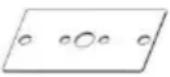 | / | / | / | Y | Y |
| 18 | Seal Tape | 1 |  | Y | Y | Y | Y | Y |
| 19 | Screw(M5x10) | 3 |  | Y | Y | Y | Y | Y |
| 20 | Screw(M6x20) | 1 | 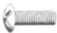 | Y | Y | Y | Y | Y |
| 21 | Self-tapping Screw | 4 |  | Y | Y | Y | Y | Y |
| 22 | M5 Nut | 3 |  | Y | Y | Y | Y | Y |
| 23 | Battery(1.5V) | 1 |  | Y | Y | Y | Y | Y |
Remark: "Y" = Yes
DIY YOUR FIRE BURNER/PAN
This screw cap allows installing the Fire Pit Burner with the gas exit hole facing up or down depending on the fuel type, region, and fire feature that Fire Pit Burner uses. Install the screw cap into the center hub opposite the gas inlet. Before installing Fire Pit Burner to the gas fitting or screw cap, sure gas tape or pipe dope is applied to assure of no gas leaks with the
Fire Pit Burner installation.
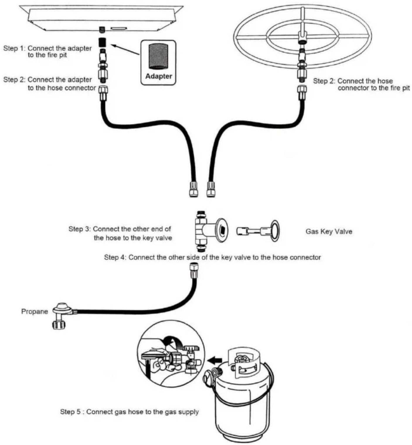
flowchart
graph TD
    A["Step 1: Connect the adapter to the fire pit"] --> B["Adapter"]
    C["Step 2: Connect the adapter to the hose connector"] --> B
    B --> D["Step 3: Connect the other end of the hose to the key valve"]
    D --> E["Step 4: Connect the other side of the key valve to the hose connector"]
    E --> F["Step 5: Connect gas hose to the gas supply"]
Gas Information
Fuel - Before making gas connections ensure appliance being installed is compatible with the available gas type.
Gas Pressure - Proper Input Pressures are required for optimum appliance performance. Gas line sizing requirements need to be made following NFPA51.
Gas Connection -Have the gas supply line installed following local building codes, if any. If not, follow ANSI (Z)223.1. Installation should be done by qualified installer approved and/or licensed as required by the locality.
Note: A listed manual gas shutoff device must be installed prior to the location of the appliance Startup - A small amount of air will be in the supply lines. When first lighting appliance it will take a short time for air purge from lines. Subsequent lighting of the appliance will not require such purging.
LP Gas Installation Considerations
Due to the fact LP (Propane) Gas is different from natural gas there are some slight differences in the installation procedures. These differences are listed here:
-
Installation of an Air Mixer. Propane is a much more volatile fuel whe compared to natural gas. For this reason, an Air Mixer is installed in the inlet of the burner element to lean out the gas, which also minimizes propane soot.
-
Drainage/Venting of the bottom of the Fire Feature. Unlike natural gas, LP gas is heavier than air. Because it is heavier than air any "unburned" gas will likely go to the bottom of the fire feature. Without proper drainage/venting at the bottom of the fire feature LP gas will collect in the bottom of the fire feature and WILL cause a very hazardous situation. For this reason, venting at the bottom of the fire feature MUST be installed to allow any unburned LP gas to escape from the bottom, thereby eliminating the hazard. Be sure to install two vents on opposing sides, each with 18 Square inches of ventilation per side.
-
Fire glass media on top of the Fire Pit Ring. Using no more than a thick layer of fire glass media ON TOP of the Burner Element in an LP fire feature is recommended. The less media there is on top of the burn element the less obstructions there are which could prevent LP gas from
being ignited at the top of the fire feature. By reducing the depth of the media you have reduced the chance of unburned LP gas from going to bottom of the fire feature.
Typical Configuration for Propane (LP) Gas Fire P Installation
- Seal Tape - Use Seal tape to seal all threaded pipe joints.
- LP Air Mixer Required - Propane requires additional air mixed with the gas to burn cleanly. Install air mixer with holes facing away from burner. The propane air mixer should be equal or greater in BTU rating than the burner.
- Proper Ventilation - Propane gas is heavier than air. Ensure ventilation holes in the lowest portion of your fire feature allow excess gas to drain.
- Gas Pressure - Between 7"WC and 11" WC (0.25 psi to 0.4 psi). We recommend a 0-20 psi high pressure regulator when. Connecting to a propane tank.
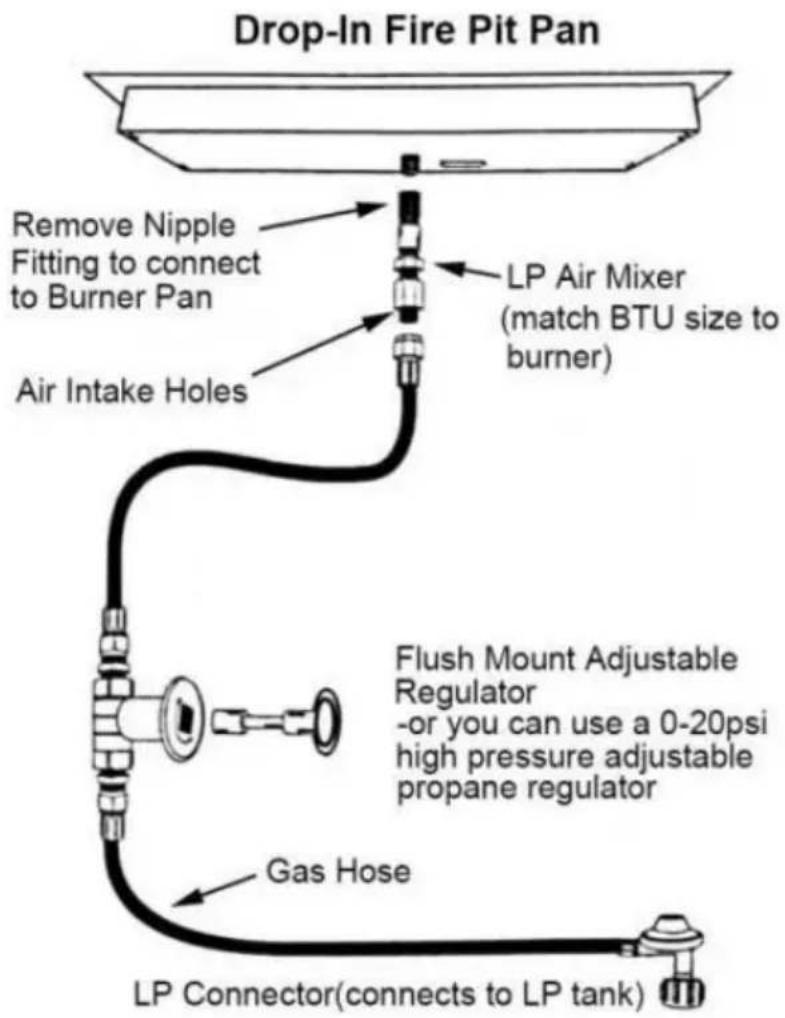
flowchart
graph TD
    A["Drop-In Fire Pit Pan"] --> B["Remove Nipple Fitting to connect to Burner Pan"]
    B --> C["Air Intake Holes"]
    C --> D["LP Air Mixer (match BTU size to burner)"]
    D --> E["Flush Mount Adjustable Regulator -or you can use a 0-20psi high pressure adjustable propane regulator"]
    E --> F["Gas Hose"]
    F --> G["LP Connector(connects to LP tank)"]
-
Clearances - Maintain a minimum of 36" clearance on all sides and 8 above your burner. Burners that are greater than 150k BTU should not be installed under any structure.
-
Fire Glass Depth-Fire glass should cover the top of the burner at a d of 1" to 2".
CAUTION:
Propane is heavier than air and will accumulate in unvented enclosures causing a combustion hazard. A minimum of 20 square inches of ventilation is required at the lowest point of an enclosed fire feature to ensure proper drainage of unburned propane gas.
natural_image
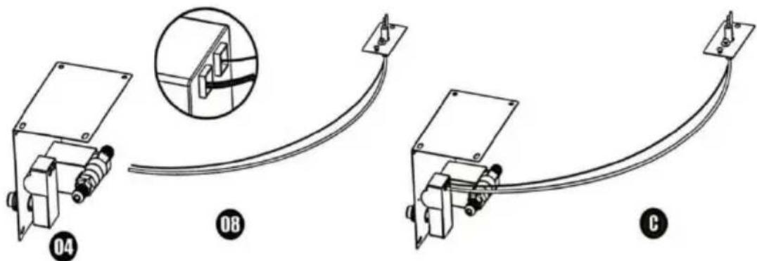
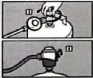
Line drawing of a simple outdoor setup with a table, air conditioner unit, and gas cylinder (no text or symbols)INSTALLATION-Ignition & Gas Valve Key Connect with Contrc Panel
- Clamp part 1 into part 2
- Screw together part 3 and part 1
- Then you have the combination-module A
natural_image
Technical line drawing of a mechanical assembly with mounting bracket and spring-loaded component (no text or symbols)- Screw off part 5, part 6 and part 7 from part 4
- Part 4 goes through part 2 and connects with part 5, 6 and 7 (screw them together)
- Then you have the combination-module B

natural_image
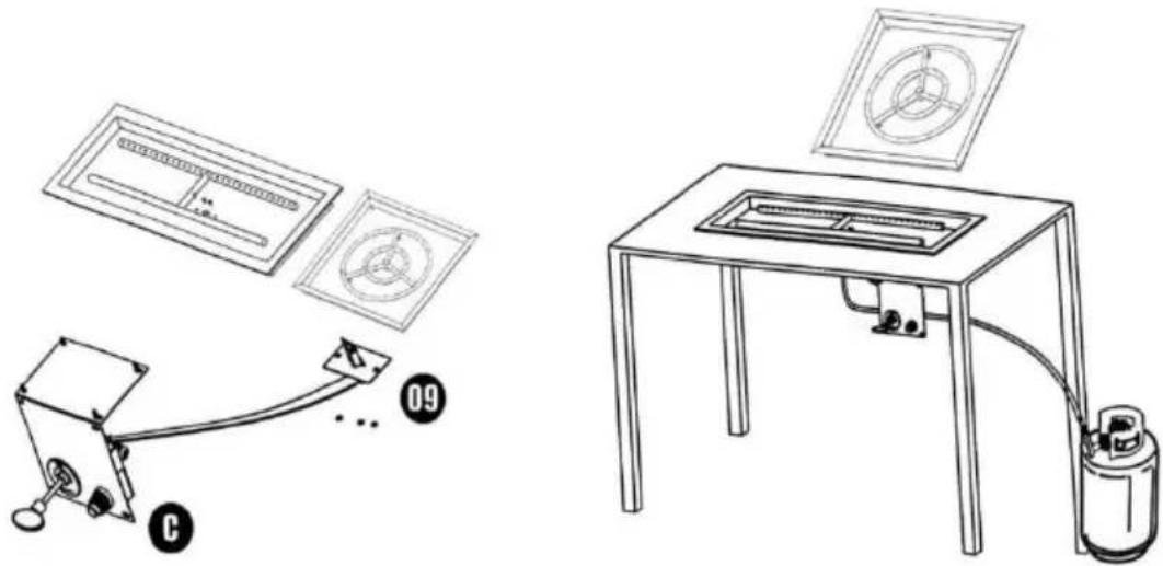
Technical line drawing of an electrical enclosure with mounting holes and internal components (no text or symbols)- Connect Part 8 (igniter wire) to part 4 (proper hole with Igniton)
- Then you have the combination-module C
- Fix Part 9 and Igniter Head to Fire Pan with 3 screws
- Fix module C on your table or somewhere else
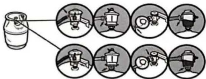
SAFE USE OR MAINTANANCE OF GAS CYLINDERS
This appliance shall be used with NATURAL or LP inlet gas supply only. The LP or CNG gas supply cylinder must be constructed and marked in accordance with the specifications for LP-gas cylinders or CNG-gas cylinders of the U.S. Department of Transportation (DOT).
The use or storage of the LP or CNG cylinder may not be used in a big garage or any other enclosed area. Cylinders must be stored outdoors in well-ventilated area out of the reach of children. Disconnected cylinders must have threaded valve plugs tightly installed.
The gas must be turned off at the supply cylinder if the appliance is not use.
Inspect the hose before each use of the appliance. The hose assembly must be replaced prior to the appliance being put into operation if there evidence of excessive abrasion or wear, or if hose is damaged. The hos assembly must be replaced with a replacement hose assembly equivalent to, or greater than, rating specified on the original hose.
The gas hose shall be located out of pathways where people may trip out or in areas where the hose may be subject to accidental damage.
Do not store or use a LP-gas supply cylinder around excessive heat; the cylinder may get too hot or cause the pressure to rise. Store the cylinder a secure upright position.
Cylinders must be fully opened and the pressure controlled by a reducing pressure regulator to operate properly.
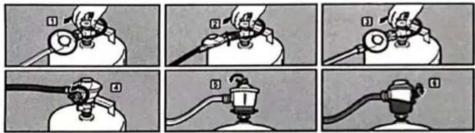
Checking for Gas Leaks
- Check all fittings and connections.
·Do not use open flame to check for leaks.
·Never use matches or open flame to test for leaks. Use soapy water or leak detector.
·Turn Valve turn cylinder valve anti-clockwise, Move leaver move regulator
lever to the on position
·To check for leaks, wet fittings with the soap-and-water solution, using a spray bottle, brush or rag. If bubbles form, or if the bubble grows, there leak. Apply the soap-and-water solution to the following connections:
a. Valve-to-regulator hose connection.
b. Regulator hose-to-regulator connection.
c. Regulator-to-cylinder connection.
When leak checking is complete, turn gas supply off at the source and rinse connections with water.
LIGHTING INSTRCUCTIONS
PLEASE CHECK THE AIR TIGHTNESS OF THE ALVE BEFORE USI
-
STOP! Before lighting this appliance, read the Gas Cylinder, Important Information, and Enclosures sections.
-
BEFORE LIGHTING: Smell all around the appliance area for gas. Be sure to smell next to the floor of the fire-pit because some gas is heavier than air and will settle in the base of the fire-pit.
-
Light a match and place it on the top and outside of the Top Burner Plate.
-
Slowly turn the manual gas valve to the "OPEN" position. The fire-pit burner should ignite between 0 to 3 seconds.
COMMON TROUBLESHOOTING
| No | Symptom | Corrective Action |
| 1 | Air in gas line | If new install, may take several attempts to purge air. |
| 2 | Debris in gas line | Confirm gas line is clear (insulation, dirt, plas excessive pipe sealer etc.) |
| 3 | Spark igniter needs adjusted | Spark igniter must be correctly aligned with burner holes. |
| 4 | Low flame height | Gas pressure is too low, have a gas special check for proper gas pressure. |
| 5 | Fire glass turning black | Propane isn't burning cleanly resulting in soo deposits. Add a propane air mixer then rinse fire glass with a 50/50 water vinegar mixture |
| 6 | Flame not evenly distributed | Check for even distribution and depth of fire glass. Reduce fire glass depth to 1" over the burner. |
CAUTION: Installing gas appliances can be dangerous. A professional gas installer must make installation to ensure the safe operation of your burner. We advise working with a certified NFI Gas Specialist.
RECOMMENDED ACCESSORIES
Glass Flame Guard-Protects flame in breezy conditions for cleaner burning of the gas and better visual presentation of the flame.
Stainless Steel Fire Pit Cover-keeps leaves, bird droppings and other debris out of the fire pit.
This product has passed strict factory testing. If any leakage is 1 please stop using it immediately and contact us for a replacement
Sanven Technology Ltd.
Address: Suite 250, 9166 Anaheim Place, Rancho Cucamonga, CA 91730
Made In China
VEVOR®
TOUGH TOOLS, HALF PRICE
Technical Support and E-Warranty Certificate www.vevor.com/support
VEVOR®
TOUGH TOOLS, HALF PRICE
natural_image
Technical line drawings of various mechanical and electrical components, including a control panel, gauges, and hoses (no text or labels)BESOIN D'AIDE? CONTACTEZ-NOUS!

natural_image
Isometric technical drawing of a rectangular electronic device with internal components and mounting holes (no text or symbols)natural_image
Technical diagram of a circular mechanical component with four symmetrical arms and bolt holes, labeled 'R' in the top right corner (no text or symbols within the diagram itself)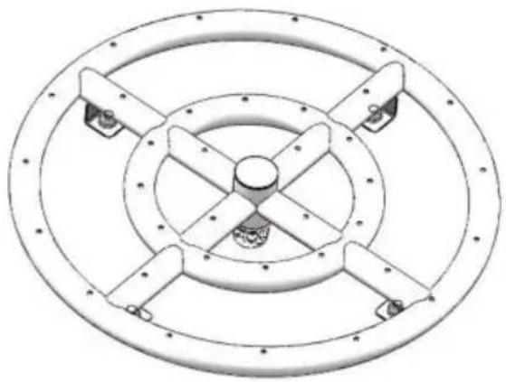
natural_image
Technical line drawing of a circular mechanical component with four symmetrical arms and central hub (no text or symbols)Modèle : 1050266


natural_image
Technical diagram of a circular mechanical component with three concentric rings and radial supports (no text or symbols)
natural_image
Technical line drawing of a circular mechanical component with radial arms and central hub (no text or symbols)Modèle : 1050267
LE FORFAIT COMPREND
flowchart
graph TD
    A["Step 1: Connect the adapter to the fire pit"] --> B["Adapter"]
    C["Step 2: Connect the adapter to the hose connector"] --> B
    B --> D["Step 3: Connect the other end of the hose to the key valve"]
    D --> E["Step 4: Connect the other side of the key valve to the hose connector"]
    E --> F["Gas Key Valve"]
    G["Step 5: Connect gas hose to the gas supply"] --> H["Propane"]
flowchart
graph TD
    A["Drop-In Fire Pit Pan"] --> B["Remove Nipple Fitting to connect to Burner Pan"]
    B --> C["Air Intake Holes"]
    C --> D["LP Air Mixer (match BTU size to burner)"]
    D --> E["Flush Mount Adjustable Regulator -or you can use a 0-20psi high pressure adjustable propane regulator"]
    E --> F["Gas Hose"]
    F --> G["LP Connector(connects to LP tank)"]
natural_image
Line drawing of a simple gas stove setup with components including a tray, vent, and gas cylinder (no text or symbols)
natural_image
Technical line drawing of a mechanical assembly with mounting bracket and spring-loaded component (no text or symbols)
natural_image
Technical line drawing of an electrical enclosure with attached components (no text or symbols)UTILISATION ET ENTRETIEN SÉCURISÉS DES BOUTEILLES DE GAZ
INSTRUCTIONS D'ÉCLAIRAGE
VEUILLEZ VÉRIFIER L'ÉTANCHÉITÉ DE L'ALVE AVANT UTILISATION !
natural_image
Technical line drawings of various electrical and mechanical components including a control panel, gauges, and hoses (no text or labels)Kundenservice@vevor.com
GEFAHR KOHLENMONOXIDGEFAHR
natural_image
Technical line drawing of a rectangular electronic device with internal components and mounting holes (no text or symbols)Parametertabelle - Modellnr. 1050266 1050267
| Modell# | Installationsgröße | R | H |
| 1050266 | 12" 12" | 1 16/25" | |
| 1050267 18" 18" 1 16/25" | |||

natural_image
Technical diagram of a circular mechanical component with four symmetrical arms and bolt holes, labeled 'R' in the top right corner (no text or symbols on the diagram itself)
natural_image
Technical line drawing of a circular mechanical component with four symmetrical arms and central hub (no text or symbols)Modellnr.: 1050266


natural_image
Technical diagram of a circular mechanical component with three concentric rings and radial supports (no text or symbols)
natural_image
Technical line drawing of a circular mechanical component with radial arms and central hub (no text or symbols)
Modellnr.: 1050267
PAKET BEINHALTET
flowchart
graph TD
    A["Step 1: Connect the adapter to the fire pit"] --> B["Adapter"]
    C["Step 2: Connect the adapter to the hose connector"] --> B
    D["Step 3: Connect the other end of the hose to the key valve"] --> E["Gas Key Valve"]
    F["Step 4: Connect the other side of the key valve to the hose connector"] --> E
    G["Step 5: Connect gas hose to the gas supply"] --> H["Propane"]
Gasinformationen
flowchart
graph TD
    A["Drop-In Fire Pit Pan"] --> B["Remove Nipple Fitting to connect to Burner Pan"]
    B --> C["Air Intake Holes"]
    C --> D["LP Air Mixer (match BTU size to burner)"]
    D --> E["Flush Mount Adjustable Regulator -or you can use a 0-20psi high pressure adjustable propane regulator"]
    E --> F["Gas Hose"]
    F --> G["LP Connector(connects to LP tank)"]
natural_image
Line drawing of a simple gas stove setup with components including a tray, vent, and gas cylinder (no text or symbols)
natural_image
Technical line drawing of a mechanical assembly with mounting bracket and spring-loaded component (no text or symbols)
natural_image
Technical line drawing of an electrical enclosure with attached components (no text or symbols)
www.vevor.com/support
VEVOR®
TOUGH TOOLS, HALF PRICE
elettronica www.vevor.com/support
BRUCIATORE/PADELLA PER FOCOLARE
MODELLO:1050262,1050263,1050264,1050266,1050267
natural_image
Technical line drawings of various electrical and mechanical components including a control panel, gauges, and hoses (no text or labels)
natural_image
Isometric technical drawing of a rectangular electronic device with internal components and mounting holes (no text or symbols)natural_image
Technical diagram of a circular mechanical component with four symmetrical arms and bolt holes, labeled 'R' in the top right corner (no text or symbols within the diagram itself)
natural_image
Technical line drawing of a circular mechanical component with four symmetrical arms and central hub (no text or symbols)Modello n.: 1050266


natural_image
Technical diagram of a circular mechanical component with three concentric rings and radial supports (no text or symbols)
natural_image
Technical line drawing of a circular mechanical component with radial arms and central hub (no text or symbols)
Modello n.: 1050267
IL PACCHETTO INCLUDE
flowchart
graph TD
    A["Step 1: Connect the adapter to the fire pit"] --> B["Adapter"]
    C["Step 2: Connect the adapter to the hose connector"] --> B
    B --> D["Step 3: Connect the other end of the hose to the key valve"]
    D --> E["Step 4: Connect the other side of the key valve to the hose connector"]
    E --> F["Gas Key Valve"]
    G["Step 5: Connect gas hose to the gas supply"] --> H["Propane"]
flowchart
graph TD
    A["Drop-In Fire Pit Pan"] --> B["Remove Nipple Fitting to connect to Burner Pan"]
    B --> C["Air Intake Holes"]
    C --> D["LP Air Mixer (match BTU size to burner)"]
    D --> E["Flush Mount Adjustable Regulator -or you can use a 0-20psi high pressure adjustable propane regulator"]
    E --> F["Gas Hose"]
    F --> G["LP Connector(connects to LP tank)"]
natural_image
Line drawing of a simple gas stove setup with components including a tray, vent, and gas cylinder (no text or symbols)
natural_image
Technical line drawing of a mechanical assembly with mounting bracket and spring-loaded component (no text or symbols)
natural_image
Technical line drawing of an electrical enclosure with attached components (no text or symbols)

natural_image
Two-step illustration showing a hand holding a device with a magnifying glass, and a close-up of the device's cable being inserted (no text or symbols present)
natural_image
Technical line drawings of various electrical and mechanical components including a control panel, gauges, and hoses (no text or labels)
natural_image
Isometric technical drawing of a rectangular electronic device with internal components and mounting holes (no text or symbols)natural_image
Technical diagram of a circular mechanical component with four symmetrical arms and bolt holes, labeled 'R' in the top right corner (no text or symbols within the diagram itself)
natural_image
Technical line drawing of a circular mechanical component with four symmetrical arms and central hub (no text or symbols)Modelo n.°: 1050266


natural_image
Technical diagram of a circular mechanical component with three concentric rings and radial supports (no text or symbols)
natural_image
Technical line drawing of a circular mechanical component with radial arms and central hub (no text or symbols)
Modelo n.°: 1050267
EL PAQUETE INCLUYE
flowchart
graph TD
    A["Step 1: Connect the adapter to the fire pit"] --> B["Adapter"]
    C["Step 2: Connect the adapter to the hose connector"] --> B
    B --> D["Step 3: Connect the other end of the hose to the key valve"]
    D --> E["Step 4: Connect the other side of the key valve to the hose connector"]
    E --> F["Gas Key Valve"]
    G["Step 5: Connect gas hose to the gas supply"] --> H["Propane"]
flowchart
graph TD
    A["Drop-In Fire Pit Pan"] --> B["Remove Nipple Fitting to connect to Burner Pan"]
    B --> C["Air Intake Holes"]
    C --> D["LP Air Mixer (match BTU size to burner)"]
    D --> E["Flush Mount Adjustable Regulator -or you can use a 0-20psi high pressure adjustable propane regulator"]
    E --> F["Gas Hose"]
    F --> G["LP Connector(connects to LP tank)"]
natural_image
Line drawing of a simple gas stove setup with components including a tray, vent, and gas cylinder (no text or symbols)
natural_image
Technical line drawing of a mechanical assembly with mounting bracket and spring-loaded component (no text or symbols)
natural_image
Technical line drawing of an electrical enclosure with attached components (no text or symbols)USO SEGURO O MANTENIMIENTO DE CILINDROS DE GAS
natural_image
Technical line drawings of various electrical and mechanical components including a control panel, gauges, and hoses (no text or labels)POTRZEBUJESZ POMOCY? SKONTAKTUJ SIĘ Z NAMI!

natural_image
Isometric technical drawing of a rectangular electronic device with internal components and mounting holes (no text or symbols)Tabela parametrów - model nr 1050266 1050267
natural_image
Technical diagram of a circular mechanical component with four symmetrical arms and bolt holes, labeled 'R' in the top right corner (no text or symbols on the diagram itself)
natural_image
Technical line drawing of a circular mechanical component with four symmetrical arms and central hub (no text or symbols)Numer modelu: 1050266

natural_image
Technical diagram of a circular mechanical component with three concentric rings and radial supports (no text or symbols)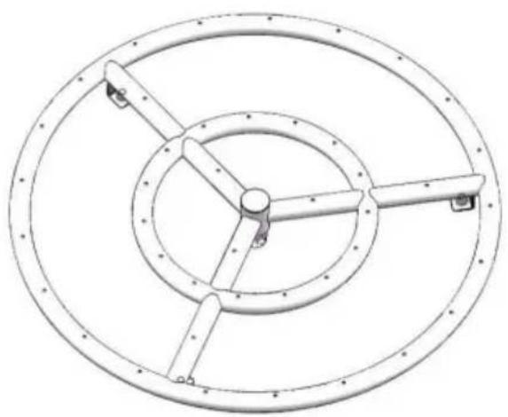
natural_image
Technical line drawing of a circular mechanical component with radial arms and central hub (no text or symbols)
Numer modelu: 1050267
ZAWARTOŚĆ PAKIETU
flowchart
graph TD
    A["Step 1: Connect the adapter to the fire pit"] --> B["Adapter"]
    C["Step 2: Connect the adapter to the hose connector"] --> B
    B --> D["Step 3: Connect the other end of the hose to the key valve"]
    D --> E["Step 4: Connect the other side of the key valve to the hose connector"]
    E --> F["Gas Key Valve"]
    G["Step 5: Connect gas hose to the gas supply"] --> H["Propane"]
Informacje o gazie
flowchart
graph TD
    A["Drop-In Fire Pit Pan"] --> B["Remove Nipple Fitting to connect to Burner Pan"]
    B --> C["Air Intake Holes"]
    C --> D["LP Air Mixer (match BTU size to burner)"]
    D --> E["Flush Mount Adjustable Regulator -or you can use a 0-20psi high pressure adjustable propane regulator"]
    E --> F["Gas Hose"]
    F --> G["LP Connector(connects to LP tank)"]
natural_image
Line drawing of a simple gas stove setup with components including a tray, vent, and gas cylinder (no text or symbols)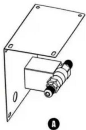
natural_image
Technical line drawing of a mechanical assembly with mounting brackets and a spring-loaded component (no text or symbols)
natural_image
Technical line drawing of an electrical enclosure with attached components (no text or symbols)BEZPIECZNE UŻYTKOWANIE LUB KONSERWACJA BUTLI GAZOWYCH
INSTRUKCJA OŚWIETLENIA
PRZED UŻYCIEM SPRAWDZIĆ SZCZELNOŚĆ ALWY!
natural_image
Technical line drawings of various electrical and mechanical components including a control panel, gauges, and hoses (no text or labels)HULP NODIG? NEEM CONTACT MET ONS OP!
Klantenservice@vevor.com
WAARSCHUWINGWAARSCHUWING

natural_image
Isometric technical drawing of a rectangular electronic device with internal components and mounting holes (no text or symbols)Parametertabel - Modelnr. 1050266 1050267
| Model# | Installatiegrootte | R | H |
| 1050266 | 12" 12" | 1 16/25" | |
| 1050267 18" 18" 1 | 16/25" |
natural_image
Technical diagram of a circular mechanical component with four symmetrical arms and bolt holes, labeled 'R' in the top right corner (no text or symbols on the diagram itself)
natural_image
Technical line drawing of a circular mechanical component with four symmetrical arms and central hub (no text or symbols)Modelnr.: 1050266
natural_image
Technical diagram of a circular mechanical component with three concentric rings and radial supports (no text or symbols)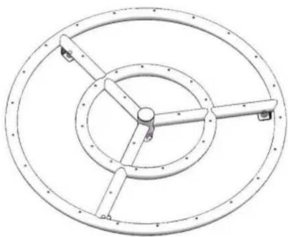
natural_image
Technical line drawing of a circular mechanical component with radial arms and central hub (no text or symbols)
Modelnr.: 1050267
PAKKET INBEGREPEN
| Geen componenten Hoeveelheid | Afbeelding | Past op model# | ||||||
| 1050262 | 1050263 | 1050264 | 1050266 | 1050267 | ||||
| 1 | Vuurkorfbrander | 1 |  | EN | EN | EN | / | / |
 | / | / | / | EN | / | |||
 | / | / | / | / | EN | |||
| 2 | Vuurkorf Pan | 1 | 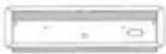 | EN | EN | EN | / | / |
| 3 | 4,4ft propaan Regelaar slang | 1 | 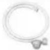 | EN | EN | EN | EN | EN |
| 4 | 4ft verbinding Slang | 1 | 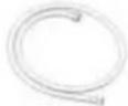 | EN | EN | EN | EN | EN |
| 5 | 1/2" Afsluiter Kogelkraan | 1 | 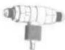 | EN | EN | EN | EN | EN |
| 6 | 1/2" Luchtmenger Ventiel | 1 | 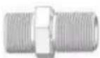 | EN | EN | EN | EN | EN |
| 7 | 1/2" messing Adapter | 1 | 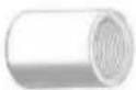 | EN | EN | EN | EN | EN |
| 8 | 1/2' roestvrij staal Verbindingsstuk | 1 | 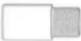 | EN | EN | EN | EN | EN |
| 9 | 5/8-18UNF Messing Verbindingsstuk | 1 | 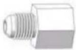 | EN | EN | EN | EN | EN |
| 10 | 1/4 Chroom Kwart-draai sleutel Ventiel | 1 | 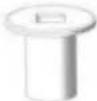 | EN | EN | EN | EN | EN |
| 11 | 3"Chroomventiel Sleutel | 1 | 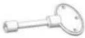 | EN | EN | EN | EN | EN |
| 12 | SS-montage Bord | 1 | 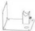 | EN | EN | EN | EN | EN |
| 10502 62 | 1050502 63 | 64 | 105010 266 | 10502 267 | ||||
| 13 | Vonk ontsteken | 1 | 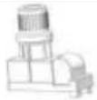 | EN | EN | EN | EN | EN |
| 14 | Ontstekingsdoos | 1 | 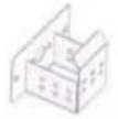 | EN | EN | EN | / | / |
| 15 | Vonk ontsteken draad | 1 |  | EN | EN | EN | EN | EN |
| 16 | Aardingsdraad | 1 | 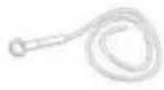 | EN | EN | EN | EN | EN |
| 17 | Verwijderbaar montageplaat voor optioneel vonk Ontsteken | 1 | 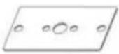 | / | / | / | EN | EN |
| 18 | Afdichtingstape | 1 | 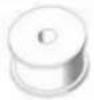 | EN | EN | EN | EN | EN |
| 19 | Schroef (M5x10) | 3 |  | EN | EN | EN | EN | EN |
| 20 Schroeven (M6x20) | 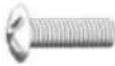 | EN | EN | EN | EN | EN1 | ||
| 21 | Zelftappend Schroef | 4 | 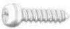 | EN | EN | EN | EN | EN |
| 22 | M5 moer | 3 |  | EN | EN | EN | EN | EN |
| 23 | Batterij (1,5V) | 1 | 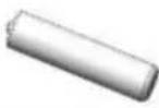 | EN | EN | EN | EN | EN |
Opmerking: "Y" = Ja
flowchart
graph TD
    A["Step 1: Connect the adapter to the fire pit"] --> B["Adapter"]
    C["Step 2: Connect the adapter to the hose connector"] --> B
    B --> D["Step 3: Connect the other end of the hose to the key valve"]
    D --> E["Step 4: Connect the other side of the key valve to the hose connector"]
    E --> F["Gas Key Valve"]
    G["Step 5: Connect gas hose to the gas supply"] --> H["Propane"]
Gasinformatie
flowchart
graph TD
    A["Drop-In Fire Pit Pan"] --> B["Remove Nipple Fitting to connect to Burner Pan"]
    B --> C["Air Intake Holes"]
    C --> D["LP Air Mixer (match BTU size to burner)"]
    D --> E["Flush Mount Adjustable Regulator -or you can use a 0-20psi high pressure adjustable propane regulator"]
    E --> F["Gas Hose"]
    F --> G["LP Connector(connects to LP tank)"]
natural_image
Line drawing of a simple gas stove setup with components including a tray, vent, and gas cylinder (no text or symbols)
natural_image
Technical line drawing of a mechanical assembly with mounting bracket and spring-loaded component (no text or symbols)
natural_image
Technical line drawing of an electrical enclosure with attached components (no text or symbols)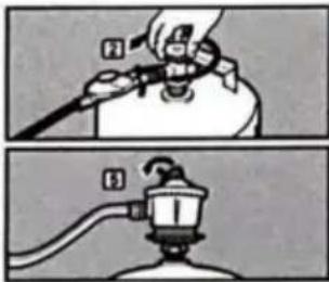
natural_image
Two-step illustration showing a hand holding a device with a magnifying glass, and a close-up of the device's handle (no text or symbols)
VERLICHTINGSINSTRUCTIES
CONTROLEER VOOR GEBRUIK DE LUCHTVASTE GARANTIE VAN DE ALVE!
ALGEMENE PROBLEEMOPLOSSING
natural_image
Technical line drawings of various electrical and mechanical components including a control panel, gauges, and hoses (no text or labels)BEHÖVER HJÄLP? KONTAKTA OSS!
Felaktig installation,

natural_image
Isometric technical drawing of a rectangular electronic device with internal components and mounting holes (no text or symbols)Parametertabell - modell#1050266 1050267
| Modell# | Installationsstorlek | R | H |
| 1050266 | 12" 12" | 1 16/25" | |
| 18" | 18" 1 16/25" | 1050267 |
natural_image
Technical diagram of a circular mechanical component with four symmetrical arms and bolt holes, labeled 'R' in the top right corner (no text or symbols on the diagram itself)
natural_image
Technical line drawing of a circular mechanical component with four symmetrical arms and central hub (no text or symbols)
natural_image
Technical diagram of a circular mechanical component with three concentric rings and radial supports (no text or symbols)
natural_image
Technical line drawing of a circular mechanical component with radial arms and central hub (no text or symbols)
flowchart
graph TD
    A["Step 1: Connect the adapter to the fire pit"] --> B["Adapter"]
    C["Step 2: Connect the adapter to the hose connector"] --> B
    B --> D["Step 3: Connect the other end of the hose to the key valve"]
    D --> E["Step 4: Connect the other side of the key valve to the hose connector"]
    E --> F["Gas Key Valve"]
    G["Step 5: Connect gas hose to the gas supply"] --> H["Propane"]
Gasinformation
flowchart
graph TD
    A["Drop-In Fire Pit Pan"] --> B["Remove Nipple Fitting to connect to Burner Pan"]
    B --> C["Air Intake Holes"]
    C --> D["LP Air Mixer (match BTU size to burner)"]
    D --> E["Flush Mount Adjustable Regulator -or you can use a 0-20psi high pressure adjustable propane regulator"]
    E --> F["Gas Hose"]
    F --> G["LP Connector(connects to LP tank)"]
natural_image
Line drawing of a simple gas stove setup with components including a tray, vent, and gas cylinder (no text or symbols)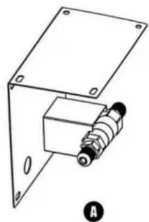
natural_image
Technical line drawing of a mechanical assembly with mounting bracket and spring-loaded component (no text or symbols)
natural_image
Technical line drawing of an electrical enclosure with attached components (no text or symbols)BELYSNINGSINSTRUKTIONER
KONTROLLERA ALVENS LUFTTÄTHET INNAN ANVÄNDNING!
Adress: Suite 250, 9166 Anaheim Place, Rancho Cucamonga, CA 91730
Tillverkad i Kina
VEVOR®
TOUGH TOOLS, HALF PRICE
www.vevor.com/support