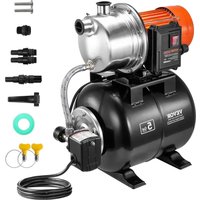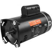
HM16058LCb - Water pump Vevor - Free user manual and instructions
Find the device manual for free HM16058LCb Vevor in PDF.


User questions about HM16058LCb Vevor
0 question about this device. Answer the ones you know or ask your own.
Ask a new question about this device
Download the instructions for your Water pump in PDF format for free! Find your manual HM16058LCb - Vevor and take your electronic device back in hand. On this page are published all the documents necessary for the use of your device. HM16058LCb by Vevor.
USER MANUAL HM16058LCb Vevor
Technical Support and E-Warranty Certificate www.vevor.com/support
Pool Pump Motor
Model:HM14065LCb/HM14095LCb/HM16075LCb
HM14075LCb/HM16058LCb/HM16085ECb
We continue to be committed to provide you tools with competitive price. "Sa "Half Price" or any other similar expressions used by us only represents an savings you might benefit from buying certain tools with us compared to the brands and does not necessarily mean to cover all categories of tools offered are kindly reminded to verify carefully when you are placing an order with us actually saving half in comparison with the top major brands.
VEVOR®
TOUGH TOOLS, HALF PRICE
Pool Pump Mot
Model: HM14065LCb/HM14095LCb/HM16075LCb
HM14075LCb/HM16058LCb/HM16085ECb
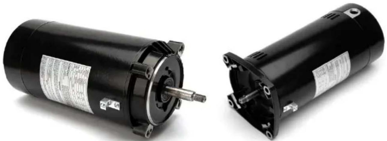
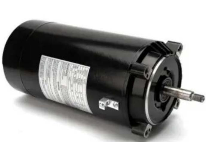
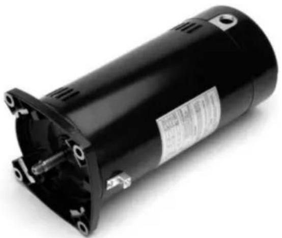
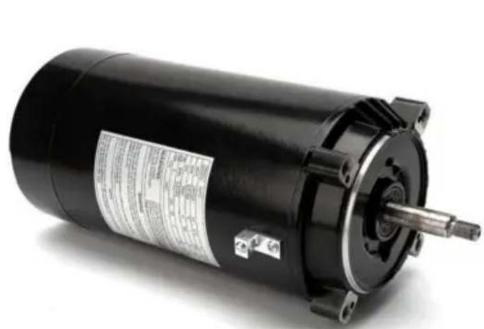
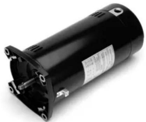
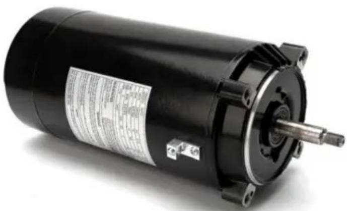
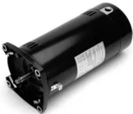
natural_image
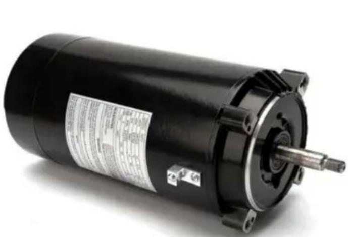
Two black electric motors with visible shafts and mounting flanges, shown from front and side views (no text or symbols)56J 56Y
Please read these operating instructions carefully before starting to work.
NEED HELP? CONTACT US!
Have product questions? Need technical support? Please feel fr contact us:
Technical Support and E-Warranty Certificate www.vevor.com/support
This is the original instruction, please read all manual instruction carefully before operating. VEVOR reserves a clear interpretation user manual. The appearance of the product shall be subject to product you received. Please forgive us that we won't inform you there are any technology or software updates on our product.
SAFETY WARNINGS AND PRECAUTIONS
-
Voltage, frequency and the wiring style should be consistent with the motor nameplate, power supply voltage should be maintained at plus 0 minus 5% of the rated operating range.
-
No more than 1000 meters above sea level.
-
Ambient air temperature not exceeding. 40
-
The motor must have a good grounding device
-
Before option must measure 500-volt megohm table winding insulation resistance to ground, and its value should be more than 0.2 megohm be dried.
-
Before starting pull action shaft, it should be flexible rotation, no fi and collisions, running should be smooth and lightly, without stagnation and the noise, if found the strange noise, overheating, burning smell, smoke or slow speed of the phenomenon, should immediately turn off power, shutdown inspection, repair it.
-
The surrounding environment should keep clean and dry and well ventilated.
-
Check whether the motor fastening is fasten.
-
Motor routine maintenance: Electrical outlet box part of the electric contacts should be kept clean and good contacts, whether the motor inlet plug, so as not to affect the motor life. Regular maintenance shall be a half a year, check the motor remove dust and oil, grease and abrasion.
-
The motor running check: When motor is operated it should also be paid attention to whether the load data in current with requirement whether the bearing has phenomena of heat and leakage, if found abnormal or sound, should be stopped immediately for inspection. Until fault is identified, do not do Starting test.
GENERAL INFORMATION
Pool Pump Motor are all fully factory tested and inspected before shipping. Damage during shipment and storage can occur. Motors not correctly matched to the power supply and/or the load will not operate
properly. These instructions are intended as a guide to identify and eliminate these problems before they are overlooked or cause further damage.
ACCEPTANCE
Check carefully for any damage that may have occurred in transit. damage or shortage is discovered, do not accept until an appropriate notation on the freight bill is made. Any damage discovered after receipt equipment should be immediately reported to the carrier.
STORAGE
A. Keep motors clean
- Store indoors
- Keep covered to eliminate airborne dust and dirt.
- Cover openings for ventilation, conduit connections, etc. to prevent entry of rodents, snakes, birds, and insects, etc.
B. Keep motors dry
- Store in a dry area indoors
- Temperature swings should be minimal to prevent condensation.
- Space heaters are recommended to prevent condensation.
- Treat unpainted flanges, shafts, and fittings with a rust inhibitor.
- Check insulation resistance before putting motor into service.
(Consult manufacturer for guidelines).
INSTALLATION
UNCRATING AND INSPECTION
After uncrating, check for any damage which may have been incurred handling. The motor shaft should turn freely by hand. Repair or replace any loose or broken parts before attempting to use the motor.
Check to be sure that motor has not been exposed to dirt, grit, or excessive moisture in shipment or storage before installation.
Measure insulation resistance (see operation). Clean and dry the windings as required.
Never start a motor which has been wet without having it thoroughly dried.
SAFETY
Motors should be installed, protected and fused in accordance with latest issue of National Electrical Code, NEMA Standard Publication No. MG 2 and local codes.
TECHNICAL INFO:
| Model No | HM14065LCb | HM14095LCb | HM16075LCb | HM14075LCb | HM16058LCb | HM16085ECb |
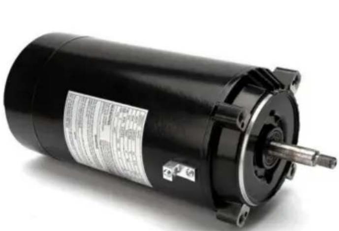
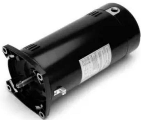
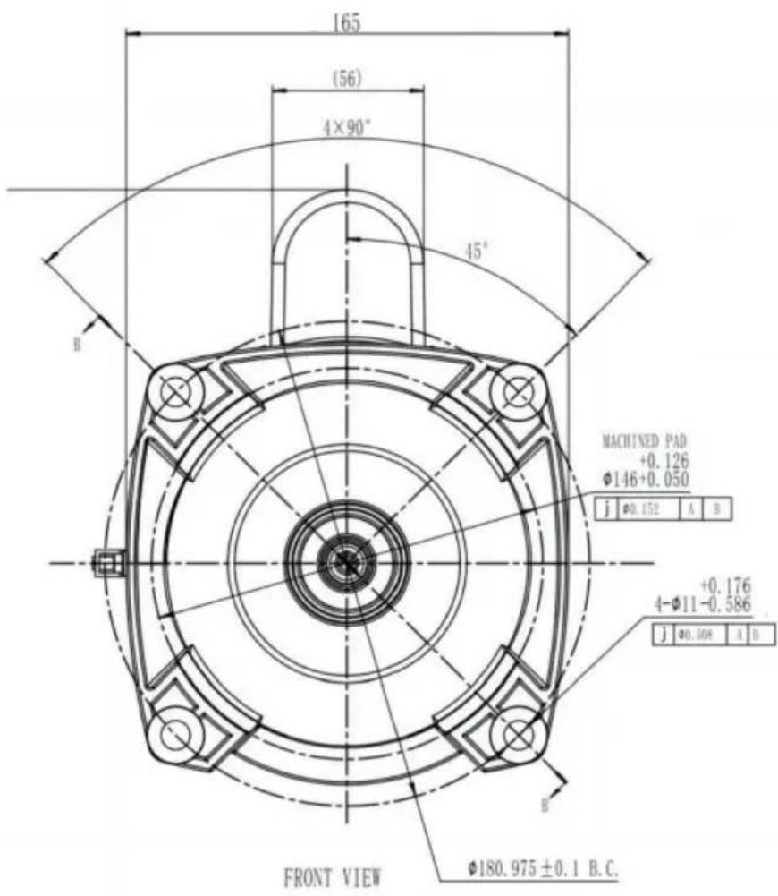
| Model flange | 56J | 56J | 56Y | 56J | 56Y | 56Y |
| Horsepower | 0.75HP | 1.5HP | 1.5HP | 1.0HP | 1HP | 2.0HP |
| no-load power | ≤460W | ≤460W | ≤350W | ≤460W | ≤350W | ≤460W |
| ATM | 40°C | 40°C | 40°C | 40°C | 40°C | 40°C |
| SF | 1.5 | 1.3 | 1.1 | 1.4 | 1.25 | 1.3 |
| AMPS | 8A(115V)/4A(230V) | 13.6A(115V)/6.8A(230V) | 12.8A(115V)/6.4A(230V) | 9.8A(115V)/4.9A(230V) | 9.0A(115V)/4.5A(230V) | 7.8A(230V) |
| AMPS(MAX LOAD) | 10A(115V)/5A(230V) | 17A(115V)/8.5A(230V) | 14A(115V)/7A(230V) | 12.4A(115V)/6.2A(230V) | 11.0A(115V)/5.5A(230V) | 10.2A(230V) |
| shaft extension | 47.5-47.75mm | 47.5-47.75mm | 23.01±0.86mm | 47.5-47.75mm | 23.01±0.86mm | 23.01±0.86mm |
| Rated Speed | 3450RPM | 3450RPM | 3450RPM | 3450RPM | 3450RPM | 3450RPM |
| Voltage | AC115/230V | AC115/230V | AC115/230V | AC115/230V | AC115/230V | AC230V |
| Frequency | 60 Hz | 60 Hz | 60 Hz | 60 Hz | 60 Hz | 60 Hz |
| Rotation | CCW | CCW | CCW | CCW | CCW | CCW |
| Insulation | F | F | F | F | F | F |
| Noise | ≤65dB | ≤65dB | ≤70dB | ≤65dB | ≤70dB | ≤70dB |
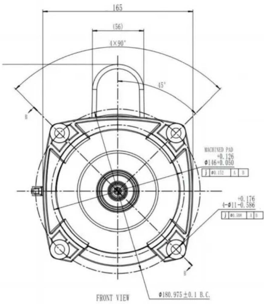
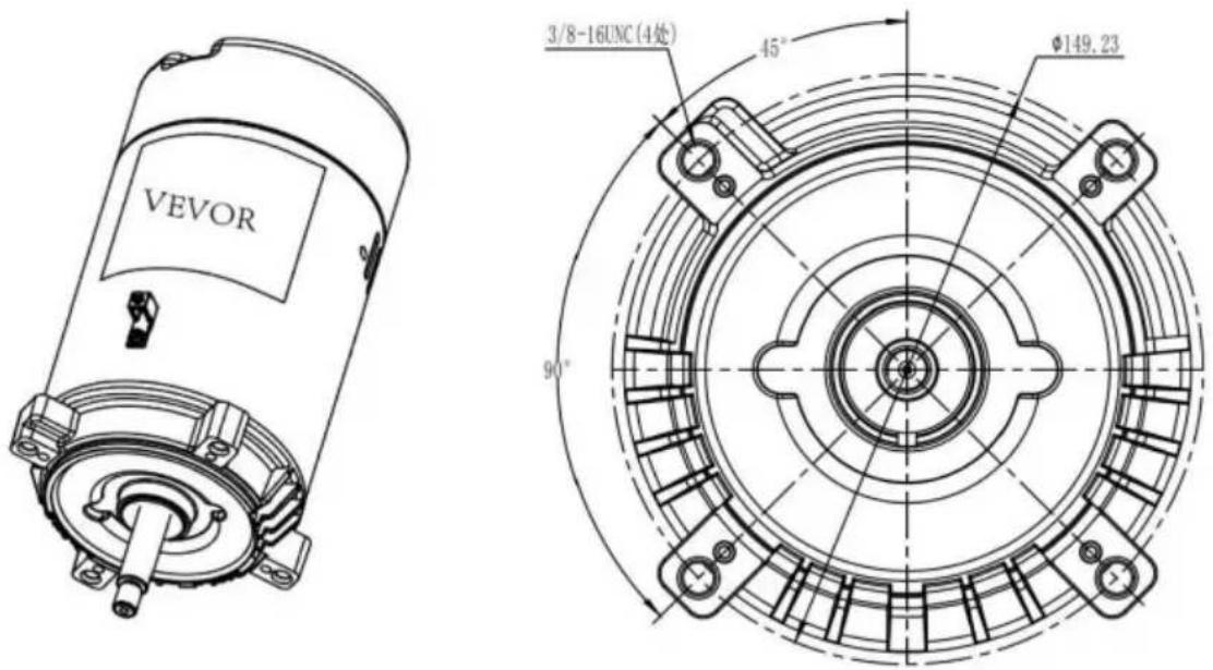
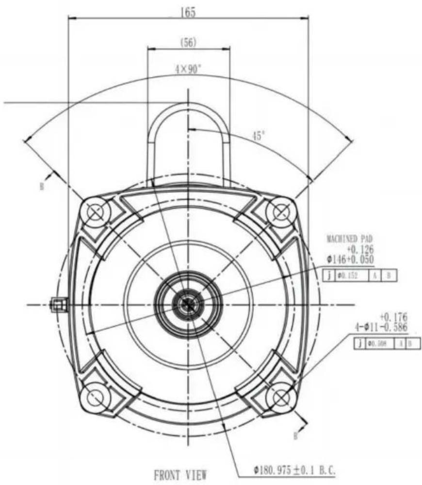
| Thread size | 3/8-16UNC | 3/8-16UNC | 4-φ10.8±0.38mm | 3/8-16UNC | 4-φ10.8±0.38mm | 4-φ10.8±0.38mm |
| outside diameter | φ142.5mm | φ142.5mm | φ164.0mm | φ142.5mm | φ164.0mm | φ164.0mm |
| Output screw teeth | 7/16-20UNF-2A | 7/16-20UNF-2A | 1/2-20UNF-2A | 7/16-20UNF-2A | 1/2-20UNF-2A | 1/2-20UNF-2A |
| Screw tooth length | 14.3-17.85m m | 14.3-17.85m m | 12.7±0.51mm | 14.3-17.85m m | 12.7±0.51mm | 12.7±0.51mm |
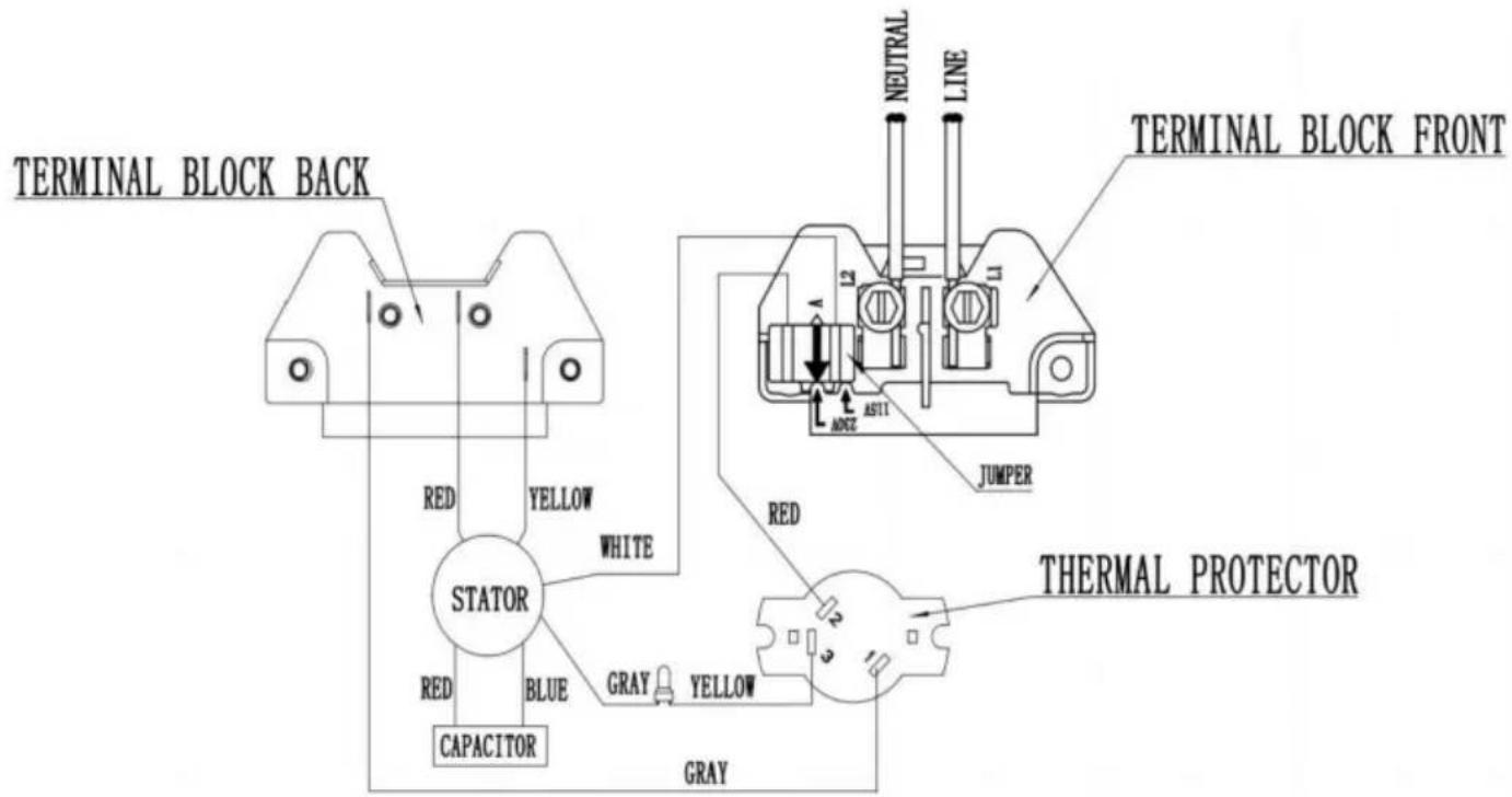
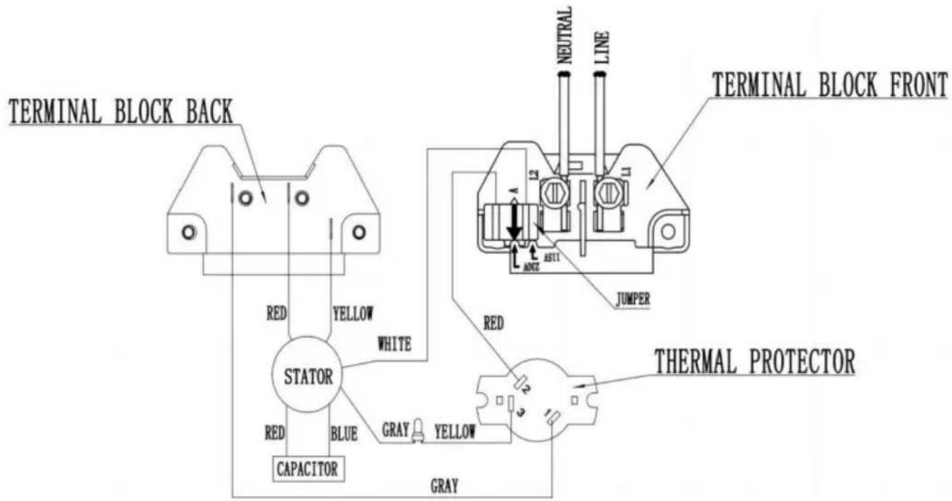
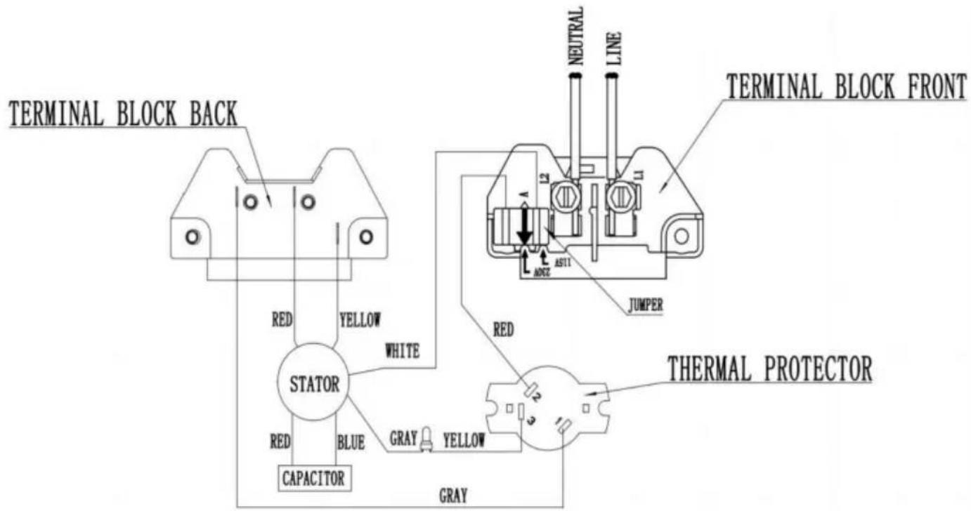
Product wiring diagram
Single voltage(HM16085ECb)
WIRING DIAGRAM-230V
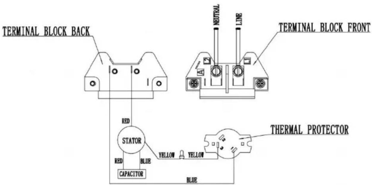
text_image
TERMINAL BLOCK BACK RED STATOR RED CAPACITOR BLUE YELLOW YELLOW YELLOW YELLOW BLUE NEUTRAL LINE TERMINAL BLOCK FRONT THERMAL PROTECTORDual voltage specification wiring
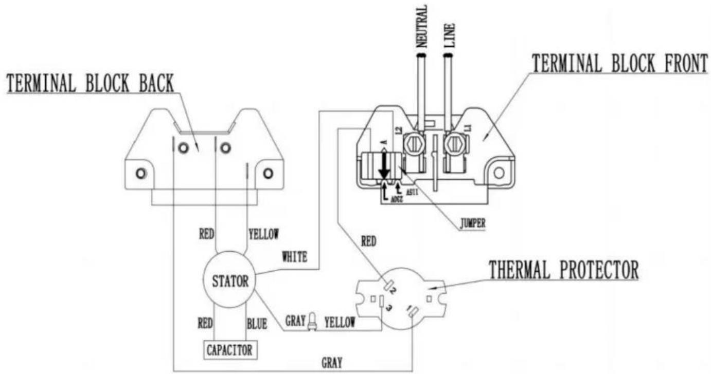
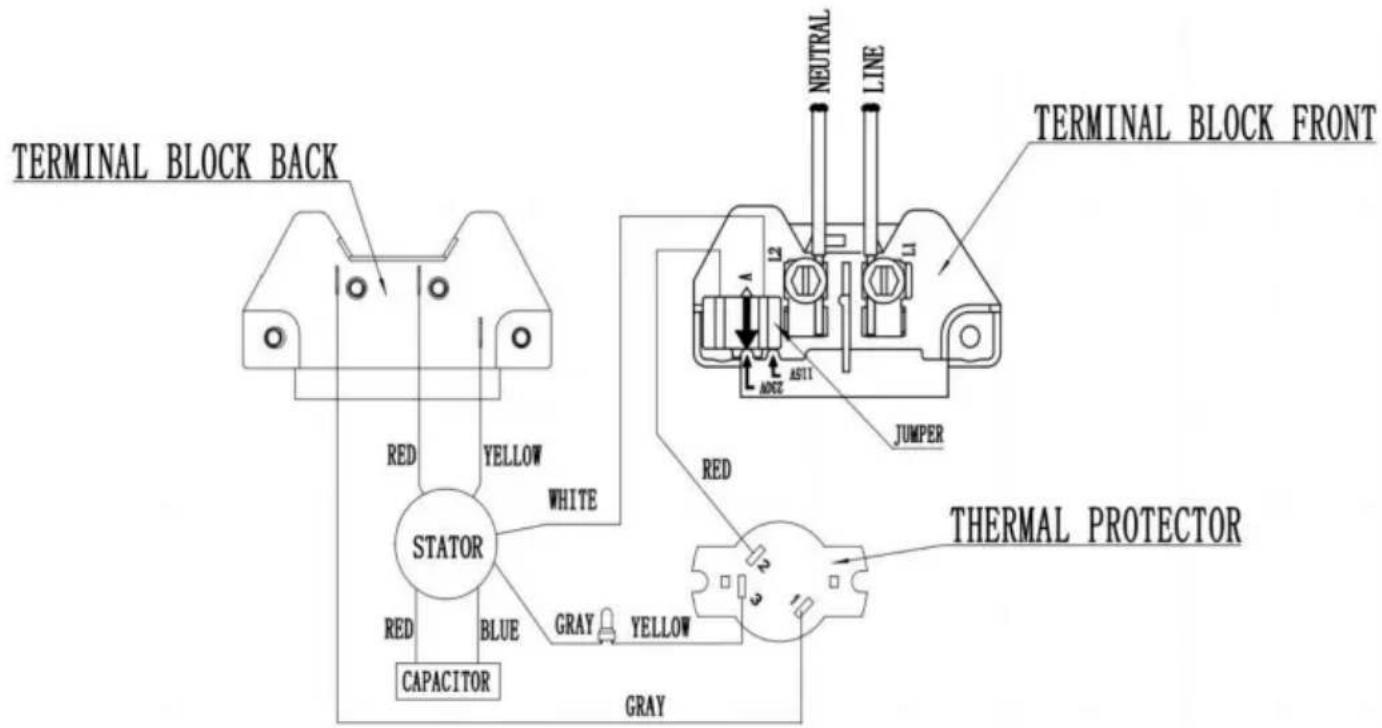
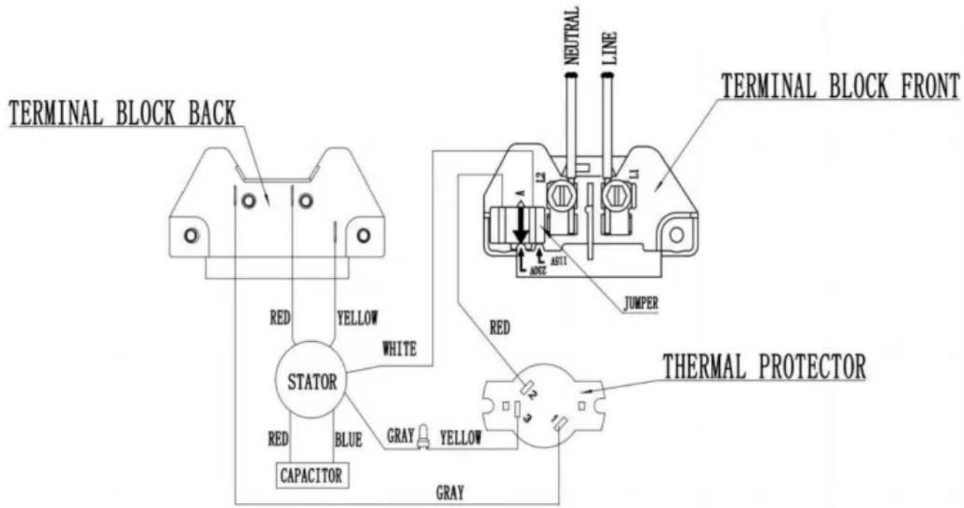
diagram(HM14065LCb/HM14095LCb/HM16075LCb/HM14075LCb/HM16058LCb)
WIRING DIAGRAM-115/230V
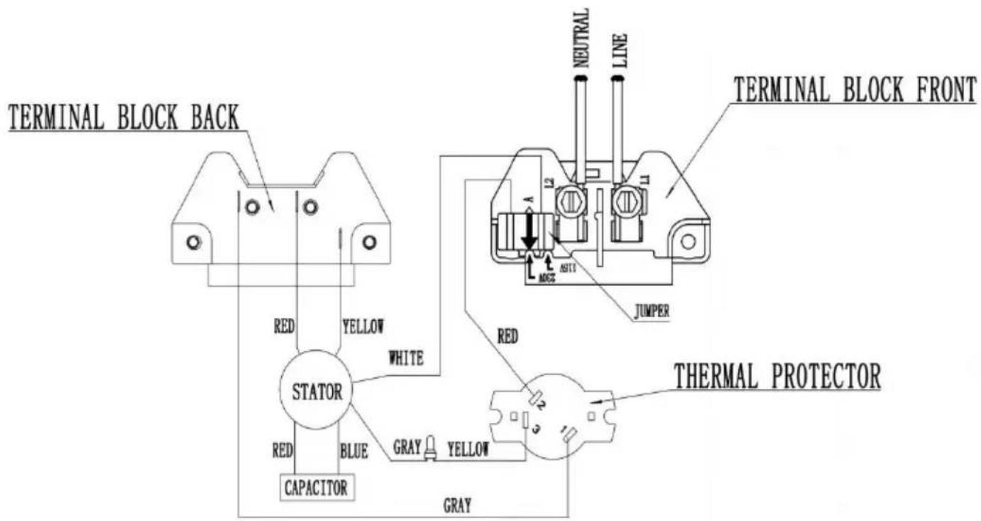
text_image
TERMINAL BLOCK BACK RED YELLOW WHITE STATOR RED BLUE CAPACITOR GRAY YELLOW GRAY RED NEUTRAL LINE JUMPER THERMAL PROTECTORPlaning
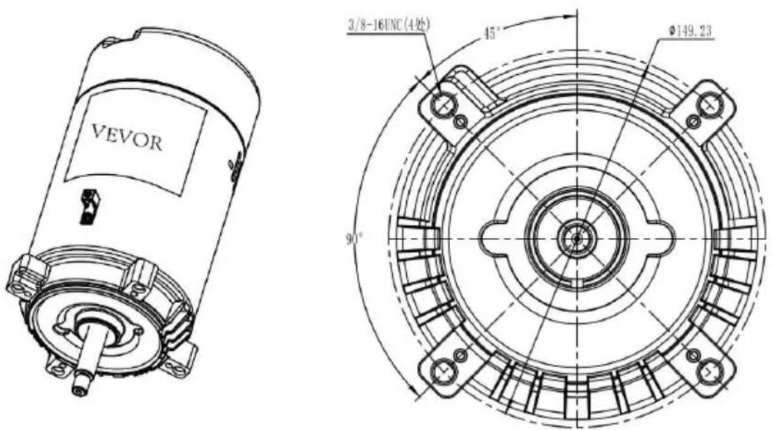
text_image
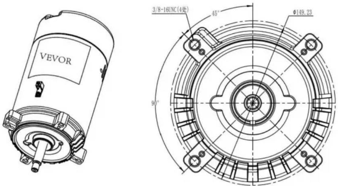
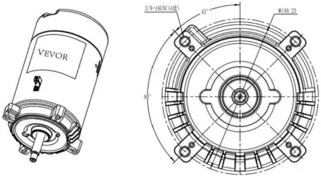
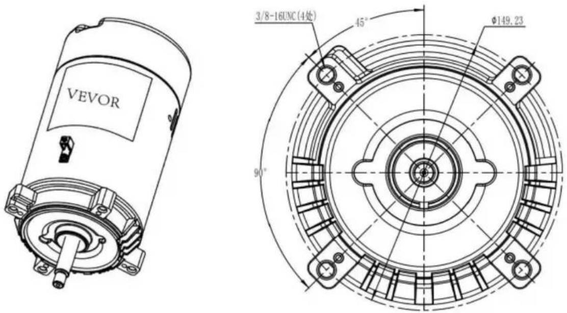
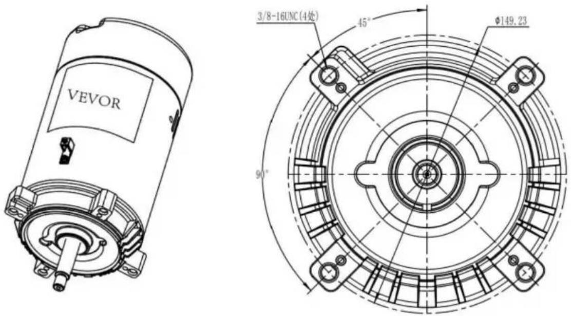
VEVOR 3/8-16UNC(4处) 45° Ø149.23 90°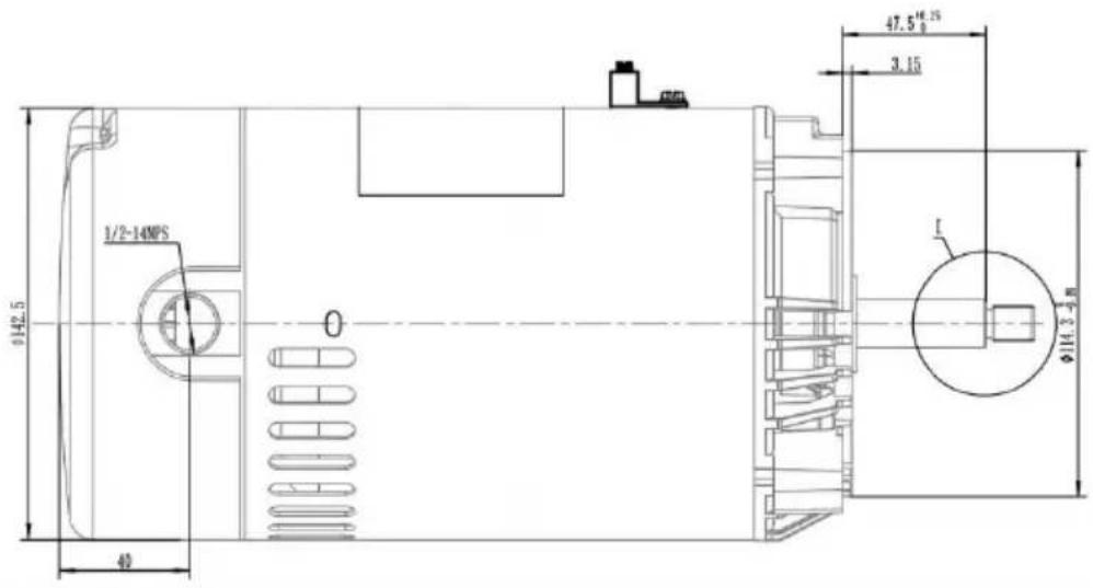
text_image
0/42.5 1/2-14MPS 40 47.5 16.25 3.15 Ø14.3-5 M L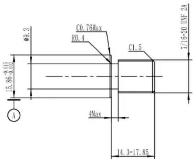
text_image
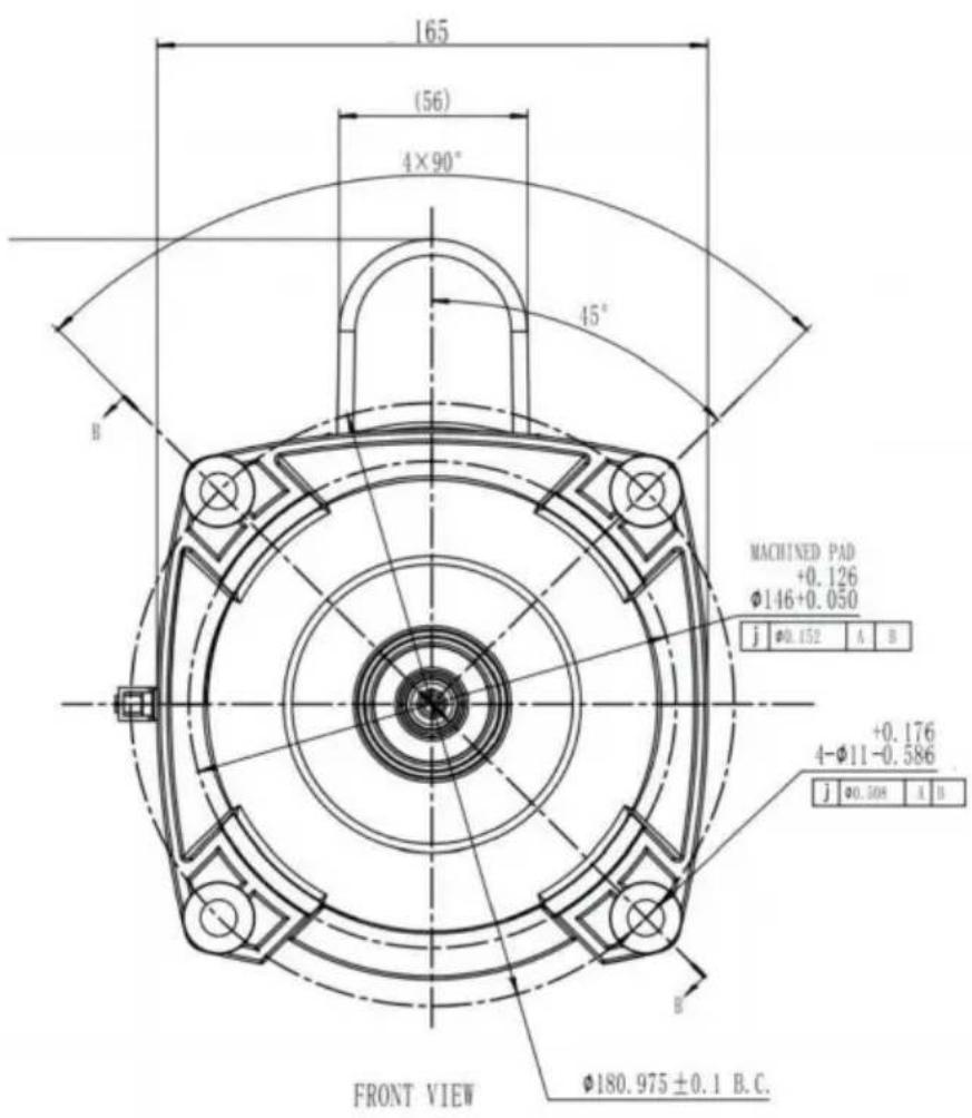
C0.76Max R0.4 Φ9.3 15.86-0.015 -0.002 A 4Max C1.5 7/16-20 UNF 2A 14.3-17.8556J(HM14065LCb/HM14095LCb/HM14075LCb)
text_image
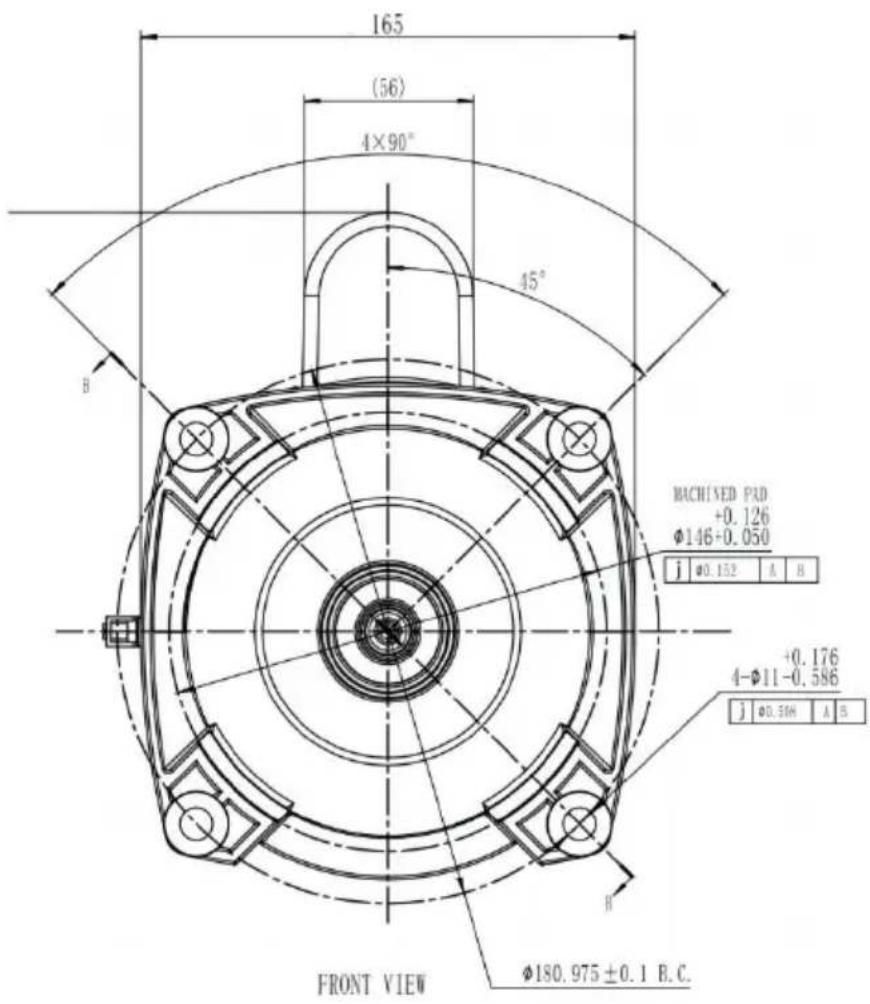
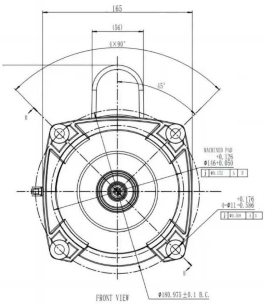
165 (56) 4×90° 45° B MACHINED PXD +0.126 Φ146+0.050 j φ0.152 A B +0.176 4-Φ11-0.586 j φ0.50H A B FRONT VIEW Φ180.975±0.1 B.C.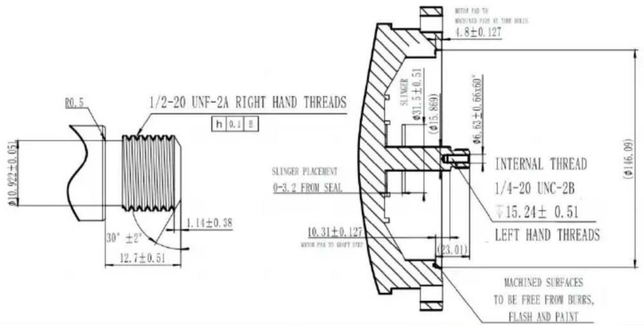
text_image
R0.5 1/2-20 UNF-2A RIGHT HAND THREADS h 0.1 B Φ10.922±0.05 30° ±2° 12.7±0.51 1.14±0.38 SLINGER PLACEMENT 0-3.2 FROM SEAL SLINGER Φ31.5±0.51 (Φ15.869) Φ6.63±0.66x60° INTERNAL THREAD 1/4-20 UNC-2B ▽15.24± 0.51 LEFT HAND THREADS MACHINED SURFACES TO BE FREE FROM BURRS, FLASH AND PAINT56Y(HM16075LCb/HM16058LCb/HM16085ECb)
Product installation precautions
- After receiving the product, open the packaging and remove it to its appearance for any damage caused by transportation. If the package is damaged or the product is damaged, please contact customer service transportation company urgently. Do not install it voluntarily.
- If the product is intact, please open the rear cover of the motor shown in the diagram.

natural_image
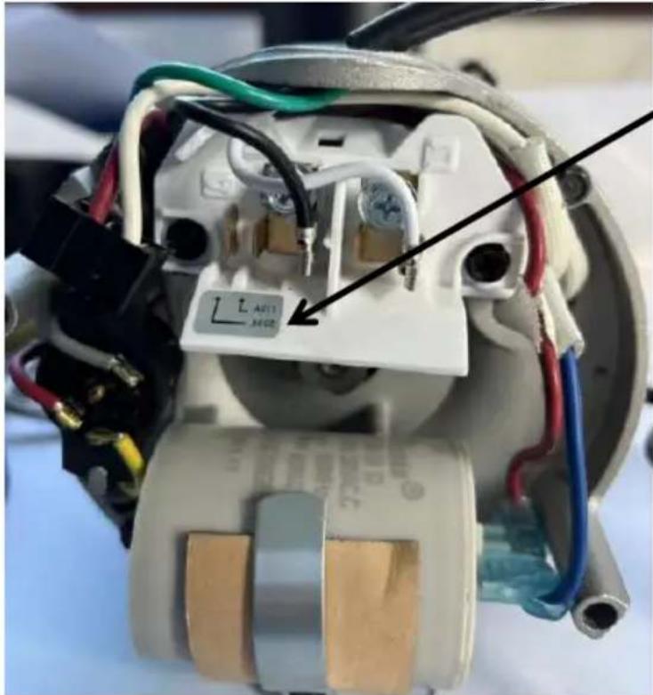
Two views of a device with exposed internal components, one showing a circular body and the other a transparent cylindrical housing (no text or symbols visible)- Remove the exposed test wire and select a voltage specification suitable for your own use. Connect the 120/230 terminals as shown in diagram. Except for HM16085ECb, all other motors are dual voltage motors, suitable for different household voltages.
natural_image
Close-up of an electrical component with wiring and a labeled component (no readable text or symbols)Be careful when choosing to ensure correct wiring, otherwise the motor may burn out
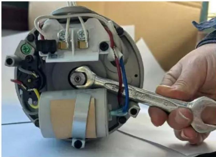
- To install the impeller of the swimming pool pump, it is necessary to remove the back cover of the motor and use a wrench to clamp the main motor shaft (to prevent the motor shaft from rotating when installing the impeller). On the other side, rotate and lock the impeller the screw thread of the motor shaft.
natural_image
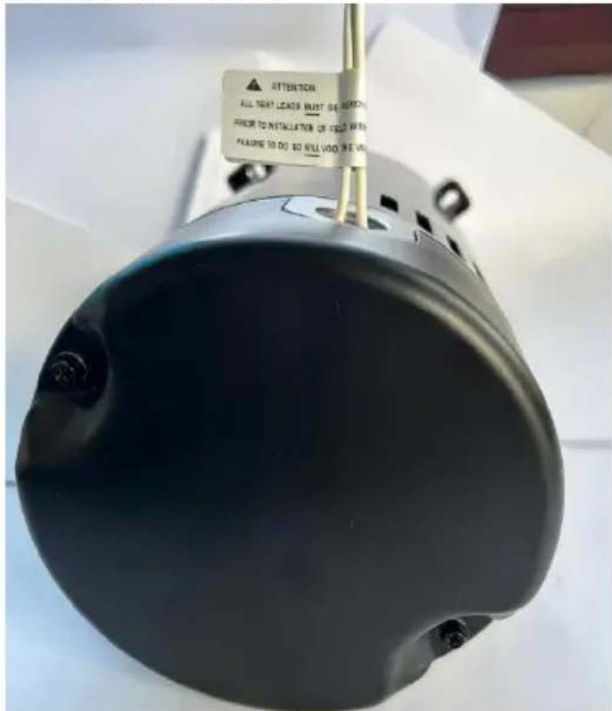
Close-up of a hand using a wrench to adjust internal components of an electric motor (no visible text or symbols)- The two white output power lines are for the convenience of testing and have practical use. After receiving the product, installing the swimming pool pump requires removing the two test leads.
text_image
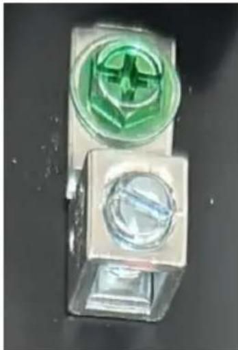
ATTENTION ALL NEAT LEADS MUST DO WORK? PRIOR TO INSTALLATOR OF FOOD WITH FEATURE TO DO $0 WILL VIND WE VOUT- Motor grounding indication, connect a grounding wire to the motor grounding device.
natural_image
Close-up of two transparent plastic electronic components with green and white markings (no visible text or symbols)Special attention: All motor models are wired with a default voltage of 230V before leaving the factory. Please adjust according to your own power supply specifications upon receipt. (If your own power supply is 230V voltage, there is no need to adjust it).
OMMON PROBLEMS AND REMEDIES
Problem 1:
When you receive the motor, please check whether the front shaft of motor can rotate. if you find that manual rotation is not possible.
Solution:
The concentricity of the motor may be damaged during transportation. Please contact the after-sales for processing
Problem 2:
The motor does not work when it is powered on.
Solution:
1) Please check the power supply to make sure the output voltage is correct.
2) Please check the wiring carefully to make sure it's the same as t wiring diagram.
Problem 3:
After the motor is powered on, it rotates slowly and cannot be started normally.
Solution:
1) Please check the power supply to make sure the output voltage is correct.
2) Please check the wiring carefully to make sure it's the same as wiring diagram.
3) Check whether the motor protector is intact and there is no open
Problem 4:
After running for a period of time, the motor heats up and stops wo
Solution:
Motor overloaded running, protector function. After half an hour of coo try again.
Made In China
anufacturer:Changzhou Honest Electric CO.,LTD
Address: No. 60, Yinxing Road, Zhonglou, Changzhou, Jiangsu, China
VEVOR®
TOUGH TOOLS, HALF PRICE
Technical Support and E-Warranty Certificate www.vevor.com/support
VEVOR®
TOUGH TOOLS, HALF PRICE
HM14075LCb/HM16058LCb/HM16085ECb
HM14075LCb/HM16058LCb/HM16085ECb
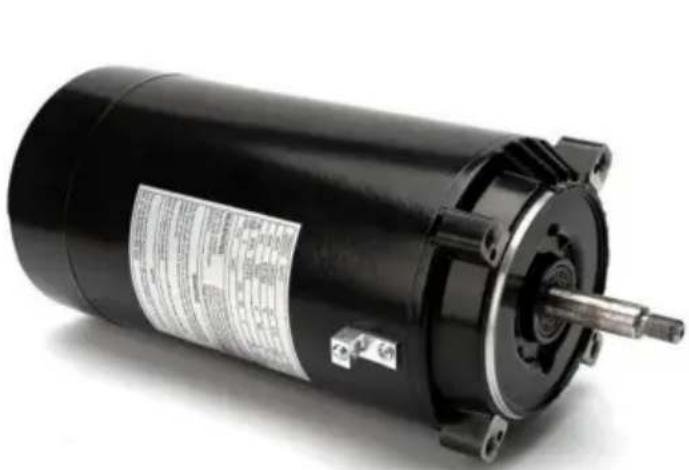
natural_image
Exterior view of a black electric motor with visible shaft and mounting bracket (no text or symbols)56J
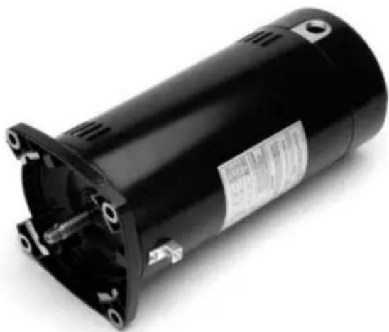
natural_image
Black electric motor with visible shaft and mounting flange (no text or symbols)56 ans
schéma (HM14065LCb/HM14095LCb/HM16075LCb/HM14075LCb/HM16058LCb)
SCHÉMA DE CÂBLAGE-115/230V
text_image
TERMINAL BLOCK BACK RED YELLOW WHITE STATOR RED BLUE CAPACITOR GRAY YELLOW GRAY RED NEUTRAL LINE JUMPER AS11 A THERMAL PROTECTORRabotage
text_image
VEVOR 3/8-16UNC(4处) 45° Φ149.23 90°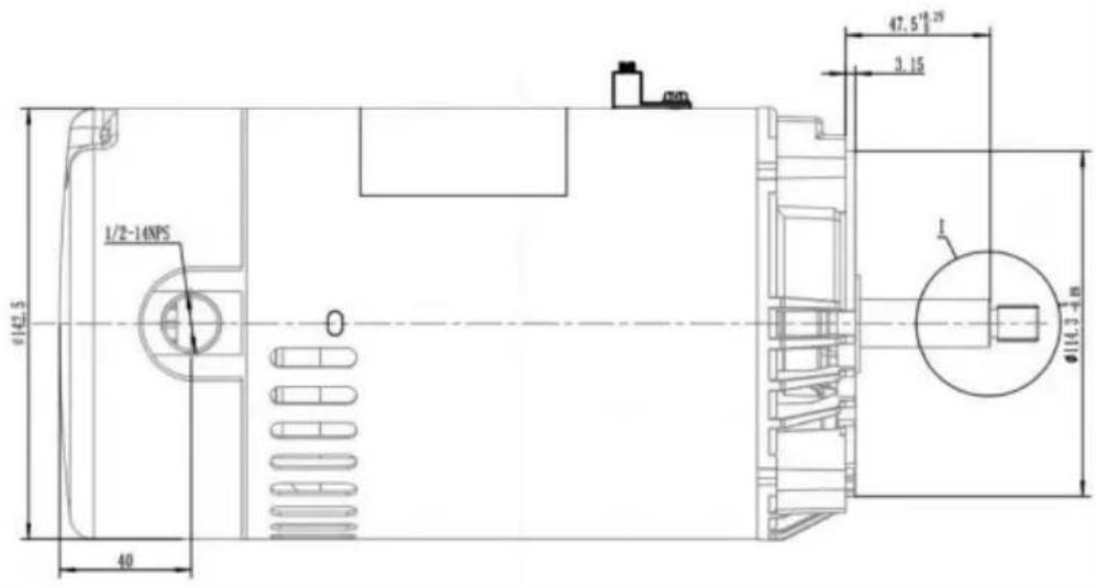
text_image
1/2-14NPS Ø142.5 40 Ø16.3-48 47.5" 19.25" 3.15 1
text_image
Ø9.3 C0.76Max R0.4 15.86+0.002 A 4Max C1.5 7/16-20 UNF 2A 14.3-17.8556J(HM14065LCb/HM14095LCb/HM14075LCb)
text_image
165 (56) 4×90° 45° B MACHINED PAD +0.126 Φ146+0.050 j Ø0.152 A B +0.176 4-Φ11-0.586 j Ø0.308 A B FRONT VIEW Φ180.975 ± 0.1 B.C.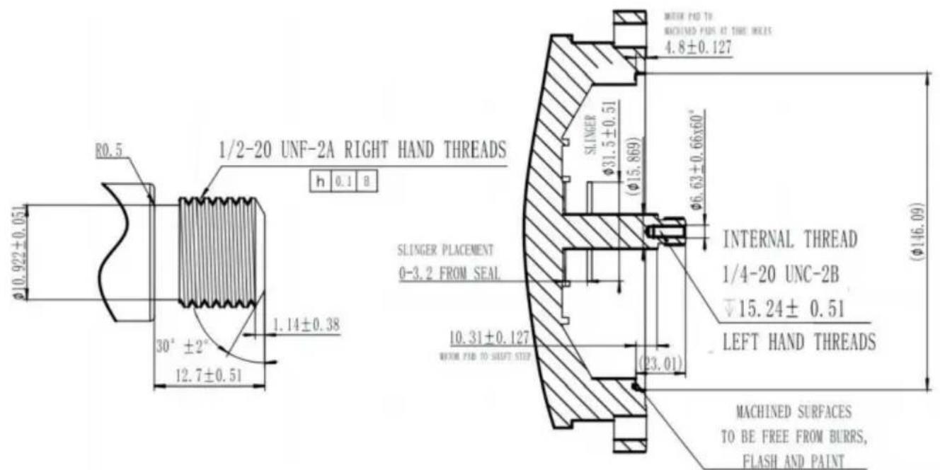
text_image
R0.5 1/2-20 UNF-2A RIGHT HAND THREADS h 0.1 B φ10.922±0.051 30° ±2° 12.7±0.51 SLINGER PLACEMENT 0-3.2 FROM SEAL 10.31±0.127 WITH PAD TO SHAFT STEP SLINGER φ31.5±0.51 (φ15.869) φ6.63±0.66x60° INTERNAL THREAD 1/4-20 UNC-2B ▽15.24± 0.51 LEFT HAND THREADS MACHINED SURFACES TO BE FREE FROM BURRS, FLASH AND PAINT56Y(HM16075LCb/HM16058LCb/HM16085ECb)
natural_image
Two views of a black circular device with visible internal components and wiring, placed on a white surface (no text or symbols)natural_image
Close-up of an electrical switch assembly with wires and components, no visible text or symbolsnatural_image
Close-up of a hand using a wrench to adjust internal components of an electric motor (no visible text or symbols)natural_image
Close-up of two transparent plastic electronic components with green and white spherical features (no visible text or symbols)Adresse : n° 60, Yinxing Road, Zhonglou, Changzhou, Jiangsu, Chine
VEVOR®
TOUGH TOOLS, HALF PRICE
Modell: HM14065LCb/HM14095LCb/HM16075LCb
HM14075LCb/HM16058LCb/HM16085ECb
Modell: HM14065LCb/HM14095LCb/HM16075LCb HM14075LCb/HM16058LCb/HM16085ECb
natural_image
Exterior view of a black electric motor with visible shaft and mounting bracket (no text or symbols)56J
natural_image
Black electric motor with visible shaft and mounting flange (no text or symbols)56J
Diagramm (HM14065LCb/HM14095LCb/HM16075LCb/HM14075LCb/HM16058LCb)
SCHALTPLAN - 115/230 V
text_image
TERMINAL BLOCK BACK RED YELLOW WHITE STATOR RED BLUE CAPACITOR GRAY YELLOW GRAY RED JUMPER NEUTRAL LINE A AS11 ADCZ THERMAL PROTECTORHobeln
text_image
VEVOR 3/8-16UNC(4处) 45° Φ149.23 90°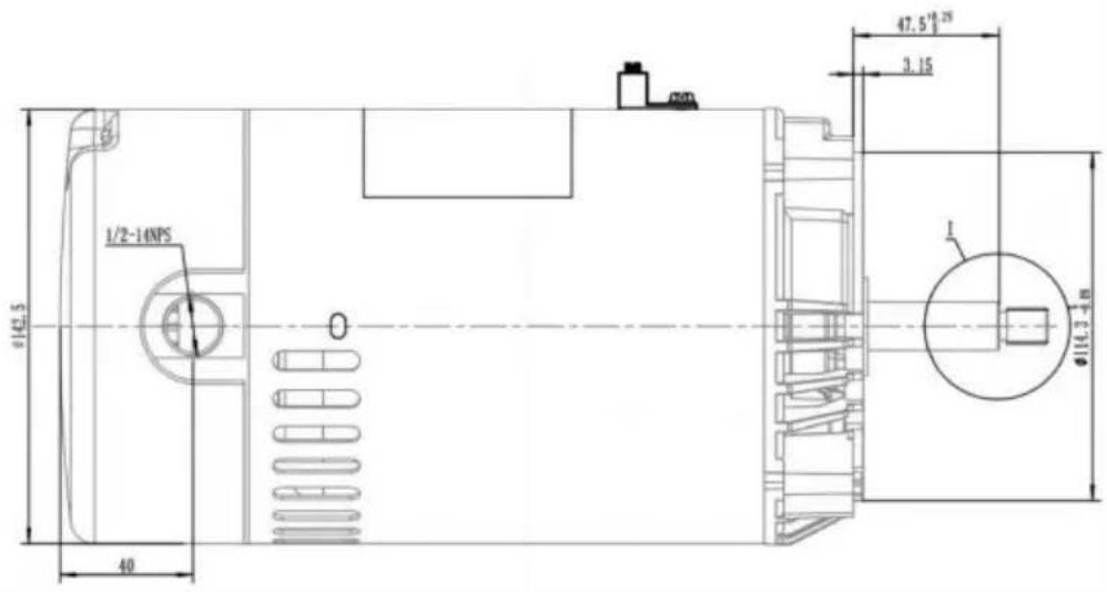
text_image
1/2-14NPS Ø142.5 40 Ø16.3-48 47.5" 19.25" 3.15 1
text_image
Ø9.3 C0.76Max R0.4 15.86+0.002 A 4Max C1.5 7/16-20 UNF 2A 14.3-17.8556J (HM14065LCb/HM14095LCb/HM14075LCb)
text_image
165 (56) 4×90° 45° B MACHINED PAD +0.126 Φ146+0.050 j Φ0.452 A B +0.176 4-Φ11-0.586 j Φ0.308 A B FRONT VIEW Φ180.975 ± 0.1 B.C.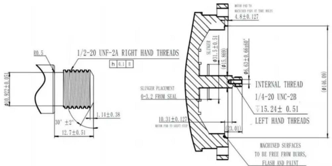
text_image
R0.5 1/2-20 UNF-2A RIGHT HAND THREADS h 0.1 B φ10.922±0.051 30° ±2° 12.7±0.51 SLINGER PLACEMENT 0-3.2 FROM SEAL 10.31±0.127 WITH PAD TO SHAFT STEP SLINGER φ31.5±0.51 (φ15.869) φ6.63±0.66x60° INTERNAL THREAD 1/4-20 UNC-2B ▽15.24± 0.51 LEFT HAND THREADS MACHINED SURFACES TO BE FREE FROM BURRS, FLASH AND PAINT56 Jahre (HM16075LCb/HM16058LCb/HM16085ECb)
natural_image
Two views of a black circular device with visible internal components and wiring, placed on a white surface (no text or symbols)natural_image
Close-up of an electrical socket with wiring and a labeled component (no readable text or symbols)natural_image
Close-up of a hand using a wrench to adjust internal components of an electric motor (no visible text or symbols)natural_image
Close-up of two small electronic components with green and white markings, no visible text or symbols.Adresse: № 60, Yinxing Road, Zhonglou, Changzhou, Jiangsu, China
VEVOR®
TOUGH TOOLS, HALF PRICE
Modello:HM14065LCb/HM14095LCb/HM16075LCb
HM14075LCb/HM16058LCb/HM16085ECb
Modello:HM14065LCb/HM14095LCb/HM16075LCb HM14075LCb/HM16058LCb/HM16085ECb
natural_image
Exterior view of a black electric motor with visible shaft and mounting flange (no text or symbols)56J
natural_image
Black industrial electric motor with visible shaft and mounting flange (no text or symbols)56Y
diagramma (HM14065LCb/HM14095LCb/HM16075LCb/HM14075LCb/HM16058LCb)
SCHEMA ELETTRICO-115/230V
text_image
TERMINAL BLOCK BACK RED YELLOW WHITE STATOR RED BLUE CAPACITOR GRAY YELLOW GRAY RED NEUTRAL LINE JUMPER AS11 A THERMAL PROTECTORPianificazione
text_image
VEVOR 3/8-16UNC(4处) 45° Φ149.23 90°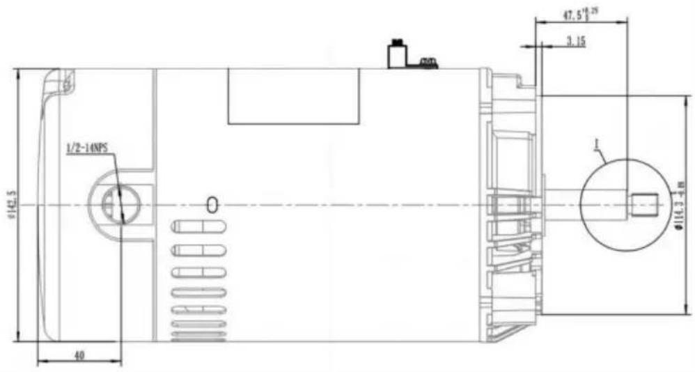
text_image
1/2-14NPS Ø142.5 40 Ø16.3-48 47.5" 19.25" 3.15 1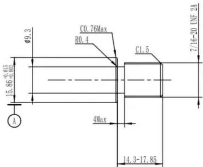
text_image
Ø9.3 C0.76Max R0.4 15.86+0.002 A 4Max C1.5 7/16-20 UNF 2A 14.3-17.8556J(HM14065LCb/HM14095LCb/HM14075LCb)
text_image
165 (56) 4×90° 45° B MACHINED PAD +0.126 Φ146+0.050 j Φ0.152 A B +0.176 4-Φ11 -0.586 j Φ0.308 A B FRONT VIEW Φ180.975 ± 0.1 B.C.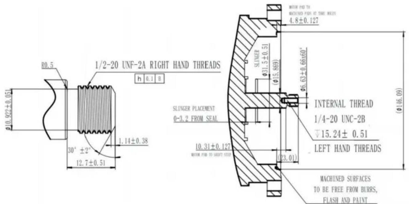
text_image
R0.5 1/2-20 UNF-2A RIGHT HAND THREADS h 0.1 B φ10.922±0.051 30° ±2° 12.7±0.51 SLINGER PLACEMENT 0-3.2 FROM SEAL 10.31±0.127 WITH PAD TO SHAFT STEP SLINGER φ31.5±0.51 (φ15.869) φ6.63±0.66x60° INTERNAL THREAD 1/4-20 UNC-2B ▽15.24± 0.51 LEFT HAND THREADS MACHINED SURFACES TO BE FREE FROM BURRS, FLASH AND PAINT56Y(HM16075LCb/HM16058LCb/HM16085ECb)
natural_image
Two views of a black circular device with visible internal components and wiring, placed on a white surface (no text or symbols)natural_image
Close-up of an electrical socket with wiring and a labeled component (no readable text or symbols)natural_image
Close-up of a hand using a wrench to adjust internal components of an electric motor (no visible text or symbols)natural_image
Close-up of two small electronic components with green and white markings, no visible text or symbols.Modelo: HM14065LCb/HM14095LCb/HM16075LCb
HM14075LCb/HM16058LCb/HM16085ECb
Modelo: HM14065LCb/HM14095LCb/HM16075LCb
HM14075LCb/HM16058LCb/HM16085ECb
natural_image
Exterior view of a black electric motor with visible shaft and mounting flanges (no text or symbols)56J
natural_image
Black industrial electric motor with visible mounting flanges and internal components (no text or symbols)56 años
diagrama (HM14065LCb/HM14095LCb/HM16075LCb/HM14075LCb/HM16058LCb)
DIAGRAMA DE CABLEADO-115/230V
text_image
TERMINAL BLOCK BACK RED YELLOW WHITE STATOR RED BLUE CAPACITOR GRAY YELLOW GRAY RED JUMPER NEUTRAL LINE A AS11 ADCZ THERMAL PROTECTORCepillado
text_image
VEVOR 3/8-16UNC(4处) 45° Φ149.23 90°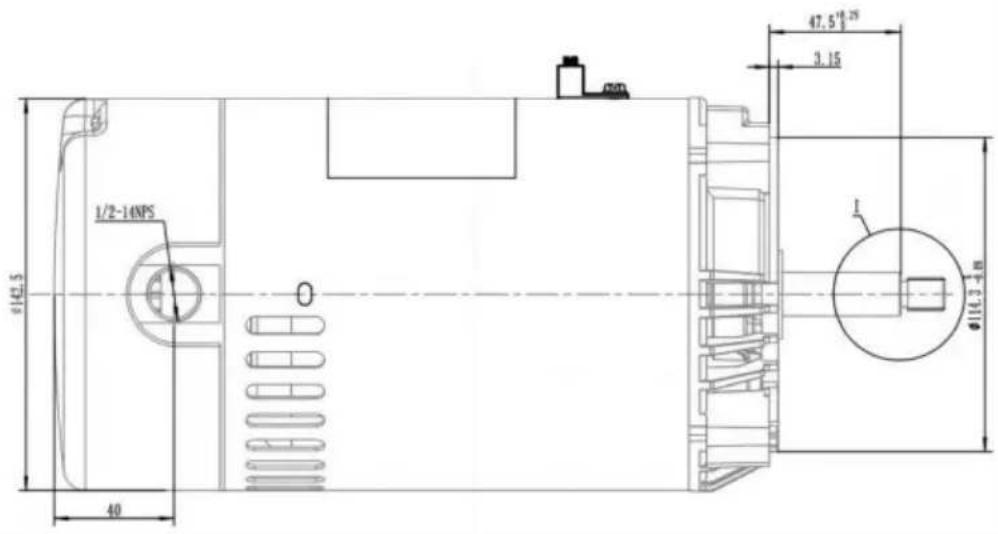
text_image
1/2-14NPS Ø142.5 40 Ø16.3-48 47.5" 19.25" 3.15 1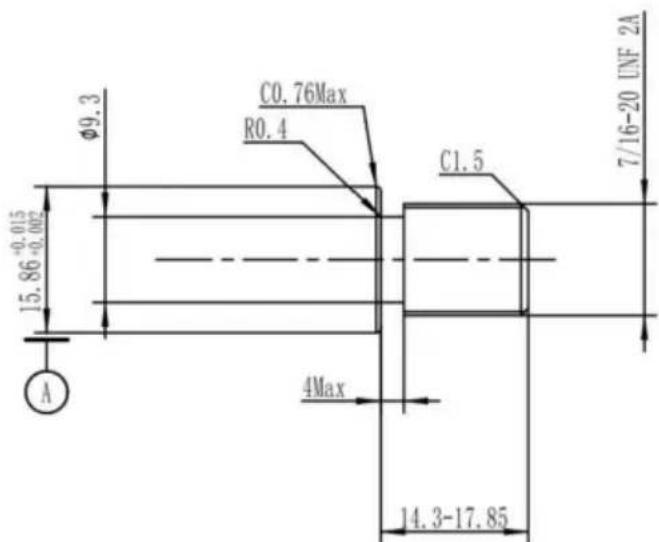
text_image
Ø9.3 C0.76Max R0.4 15.86+0.002 A 4Max C1.5 7/16-20 UNF 2A 14.3-17.8556J(HM14065LCb/HM14095LCb/HM14075LCb)
text_image
165 (56) 4×90° 45° B MACHINED PAD +0.126 Φ146+0.050 j Φ0.152 A B +0.176 4-Φ11 -0.586 j Φ0.308 A B FRONT VIEW Φ180.975 ± 0.1 B.C.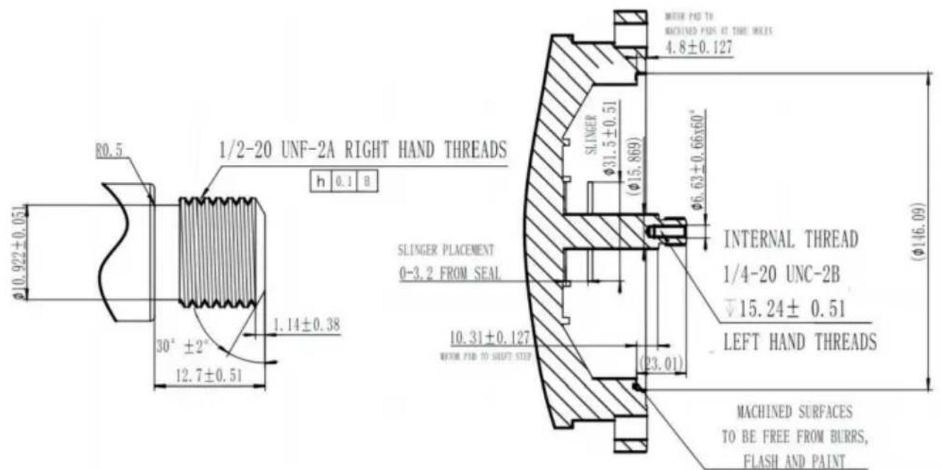
text_image
R0.5 1/2-20 UNF-2A RIGHT HAND THREADS h 0.1 B φ10.922±0.051 30° ±2° 12.7±0.51 SLINGER PLACEMENT 0-3.2 FROM SEAL 10.31±0.127 WITH PAD TO SHAFT STEP 4.8±0.127 SLINGER φ31.5±0.51 (φ15.869) φ6.63±0.66x60° INTERNAL THREAD 1/4-20 UNC-2B ▽15.24± 0.51 LEFT HAND THREADS (φ146.09) MACHINED SURFACES TO BE FREE FROM BURRS, FLASH AND PAINT56Y(HM16075LCb/HM16058LCb/HM16085ECb)
natural_image
Two views of a black circular device on a workbench, showing internal components and wiring (no visible text or symbols)natural_image
Close-up of an electrical switch assembly with wires and components, no visible text or symbolsnatural_image
Close-up of a hand using a wrench to adjust internal components of an electric motor (no visible text or symbols)natural_image
Close-up of two small electronic components with green and white markings, no visible text or symbols.Modelu:HM14065LCb/HM14095LCb/HM16075LCb
HM14075LCb/HM16058LCb/HM16085ECb
Modelu:HM14065LCb/HM14095LCb/HM16075LCb
HM14075LCb/HM16058LCb/HM16085ECb
natural_image
Exterior view of a black electric motor with visible shaft and mounting bracket (no text or symbols)56J
natural_image
Black electric motor with visible shaft and mounting flange (no text or symbols)56 lat
schemat (HM14065LCb/HM14095LCb/HM16075LCb/HM14075LCb/HM16058LCb)
SCHEMAT POŁĄCZEŃ -115/230V
text_image
TERMINAL BLOCK BACK RED YELLOW WHITE STATOR RED BLUE CAPACITOR GRAY YELLOW GRAY RED NEUTRAL LINE JUMPER AS11 A THERMAL PROTECTORStruganie
text_image
VEVOR 3/8-16UNC(4处) 45° Φ149.23 90°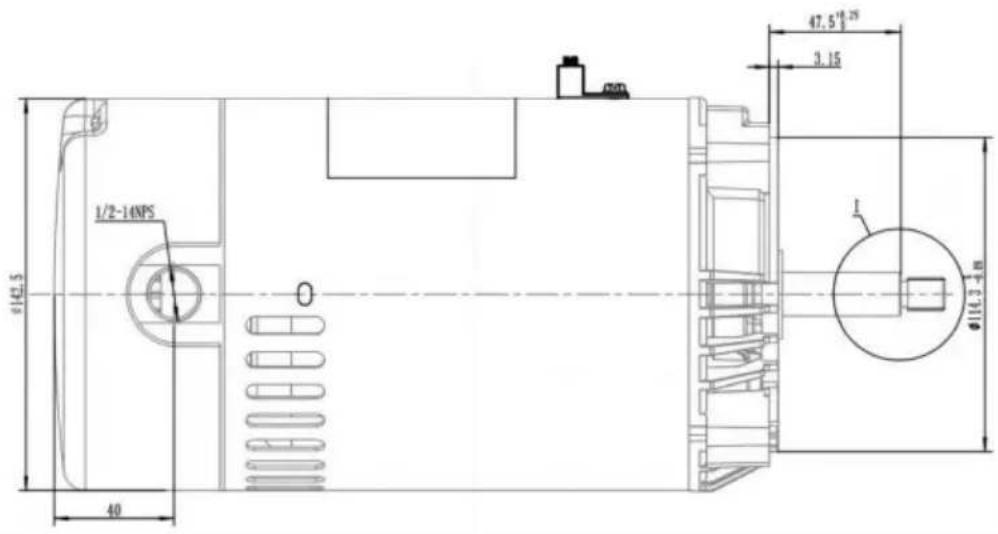
text_image
1/2-14NPS Ø142.5 40 Ø16.3-48 47.5" 19.25" 3.15 1
text_image
Ø9.3 C0.76Max R0.4 15.86+0.002 A 4Max C1.5 7/16-20 UNF 2A 14.3-17.8556J(HM14065LCb/HM14095LCb/HM14075LCb)

text_image
165 (56) 4×90° 45° B MACHINED PAD +0.126 Φ146+0.050 j Φ0.152 A B +0.176 4-Φ11-0.586 j Φ0.308 A B FRONT VIEW Φ180.975 ± 0.1 B.C.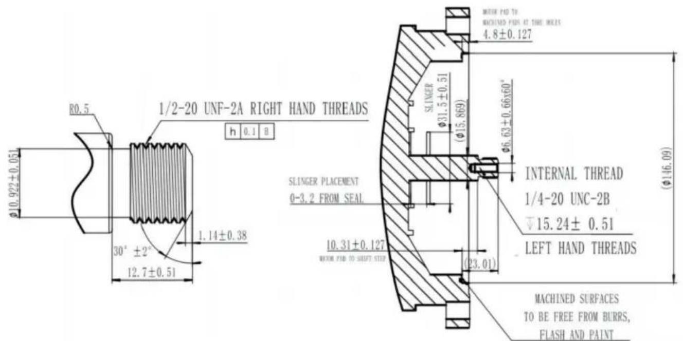
text_image
R0.5 1/2-20 UNF-2A RIGHT HAND THREADS h 0.1 B φ10.922±0.051 30° ±2° 12.7±0.51 SLINGER PLACEMENT 0-3.2 FROM SEAL 10.31±0.127 WITH PAD TO SHAFT STEP 4.8±0.127 SLINGER φ31.5±0.51 (φ15.869) φ6.63±0.66x60° INTERNAL THREAD 1/4-20 UNC-2B ▽15.24± 0.51 LEFT HAND THREADS (φ146.09) MACHINED SURFACES TO BE FREE FROM BURRS, FLASH AND PAINT56Y(HM16075LCb/HM16058LCb/HM16085ECb)
natural_image
Two views of a black circular device with visible internal components and wiring, placed on a white surface (no text or symbols)natural_image
Close-up of an electrical switch assembly with wires and components, no visible text or symbolsnatural_image
Close-up of a hand using a wrench to adjust internal components of an electric motor (no visible text or symbols)natural_image
Close-up of two small electronic components with green and white markings, no visible text or symbols.Adres: nr 60, Yinxing Road, Zhonglou, Changzhou, Jiangsu, Chiny
VEVOR®
TOUGH TOOLS, HALF PRICE
Model:HM14065LCb/HM14095LCb/HM16075LCb
HM14075LCb/HM16058LCb/HM16085ECb
Model: HM14065LCb/HM14095LCb/HM16075LCb
HM14075LCb/HM16058LCb/HM16085ECb
natural_image
Exterior view of a black electric motor with visible shaft and mounting bracket (no text or symbols)56J

natural_image
Black electric motor with visible shaft and mounting flange (no text or symbols)56J
HULP NODIG? NEEM CONTACT MET ONS OP!
diagram(HM14065LCb/HM14095LCb/HM16075LCb/HM14075LCb/HM16058LCb)
BEDRADINGSSCHEMA-115/230V
text_image
TERMINAL BLOCK BACK RED YELLOW WHITE STATOR RED BLUE CAPACITOR GRAY YELLOW GRAY RED NEUTRAL LINE JUMPER AS11 A THERMAL PROTECTORSchaven

text_image
VEVOR 3/8-16UNC(4处) 45° Φ149.23 90°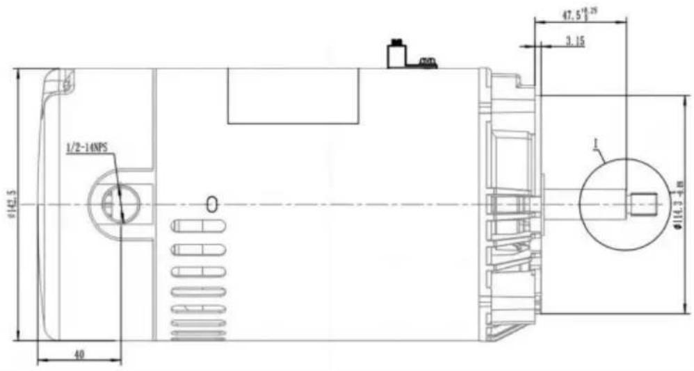
text_image
1/2-14NPS Ø142.5 40 Ø16.3-48 47.5" 19.25" 3.15 1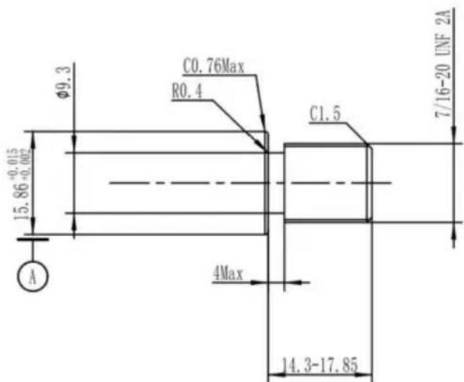
text_image
Ø9.3 C0.76Max R0.4 15.86+0.002 A 4Max C1.5 7/16-20 UNF 2A 14.3-17.8556J(HM14065LCb/HM14095LCb/HM14075LCb)
text_image
165 (56) 4×90° 45° B MACHINED PAD +0.126 Φ146+0.050 j Φ0.152 A B +0.176 4-Φ11-0.586 j Φ0.308 A B FRONT VIEW Φ180.975 ± 0.1 B.C.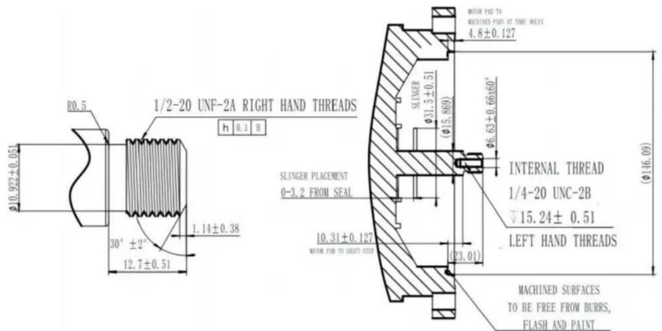
text_image
R0.5 1/2-20 UNF-2A RIGHT HAND THREADS h 0.1 B φ10.922±0.051 30° ±2° 12.7±0.51 SLINGER PLACEMENT 0-3.2 FROM SEAL 10.31±0.127 WITH PAD TO SHAFT STEP 4.8±0.127 SLINGER φ31.5±0.51 (φ15.869) φ6.63±0.66x60° INTERNAL THREAD 1/4-20 UNC-2B ▽15.24± 0.51 LEFT HAND THREADS (φ146.09) MACHINED SURFACES TO BE FREE FROM BURRS, FLASH AND PAINT56Y(HM16075LCb/HM16058LCb/HM16085ECb)
natural_image
Two views of a black circular device with visible internal components and wiring, placed on a white surface (no text or symbols)natural_image
Close-up of an electrical switch assembly with wires and components, no visible text or symbolsnatural_image
Close-up of a hand using a wrench to adjust internal components of an electric motor (no visible text or symbols)natural_image
Close-up of two small electronic components with green and white markings, no visible text or symbols.Adres: № 60, Yinxing Road, Zhonglou, Changzhou, Jiangsu, China
VEVOR®
TOUGH TOOLS, HALF PRICE
Modell: HM14065LCb/HM14095LCb/HM16075LCb
HM14075LCb/HM16058LCb/HM16085ECb
Modell: HM14065LCb/HM14095LCb/HM16075LCb HM14075LCb/HM16058LCb/HM16085ECb
natural_image
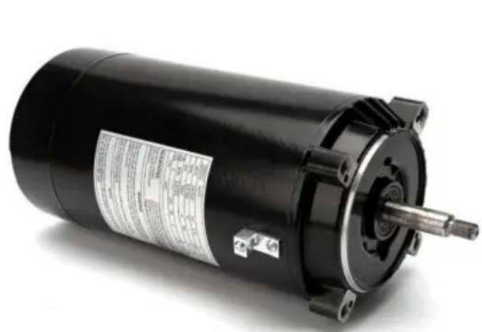
Exterior view of a black electric motor with visible shaft and mounting flange (no text or symbols)56J
natural_image
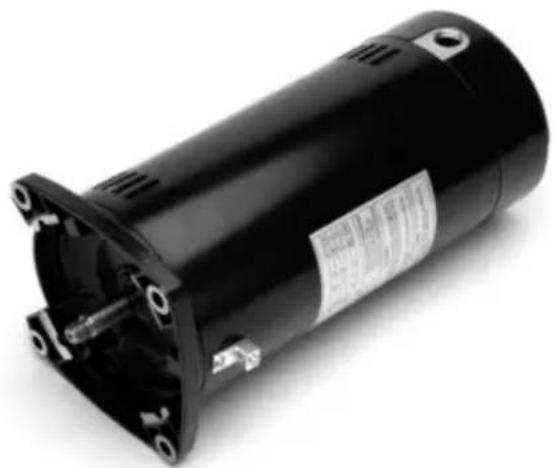
Black electric motor with visible shaft and mounting flange (no text or symbols)56Y
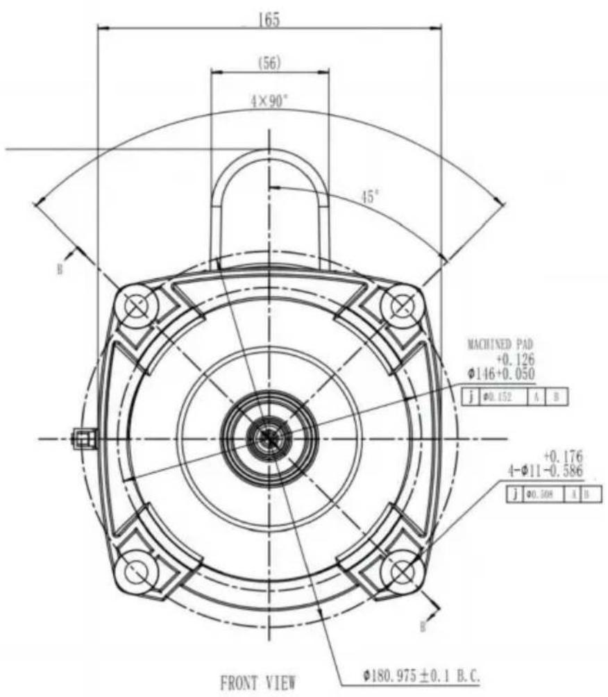
56J(HM14065LCb/HM14095LCb/HM14075LCb)
text_image
165 (56) 4×90° 45° B MACHINED PAD +0.126 Φ146+0.050 j Ø0.152 A B +0.176 4-Φ11-0.586 j Ø0.308 A B FRONT VIEW Φ180.975 ± 0.1 B.C.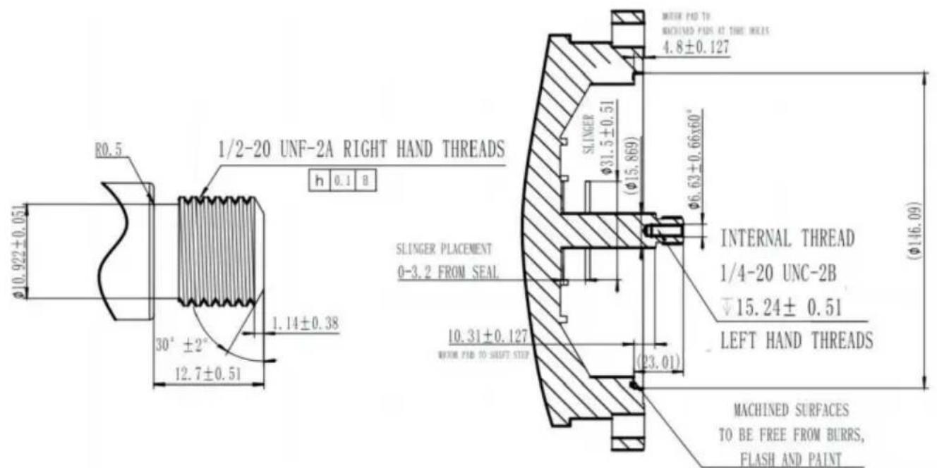
text_image
R0.5 1/2-20 UNF-2A RIGHT HAND THREADS h 0.1 B φ10.922±0.051 30° ±2° 12.7±0.51 SLINGER PLACEMENT 0-3.2 FROM SEAL 10.31±0.127 WITH PAD TO SHAFT STEP SLINGER φ31.5±0.51 (φ15.869) φ6.63±0.66x60° INTERNAL THREAD 1/4-20 UNC-2B ▽15.24± 0.51 LEFT HAND THREADS MACHINED SURFACES TO BE FREE FROM BURRS, FLASH AND PAINT56Y(HM16075LCb/HM16058LCb/HM16085ECb)
natural_image
Two views of a black circular device on a workbench, showing internal components and wiring (no visible text or symbols)natural_image
Close-up of an electrical switch assembly with wires and components, no visible text or symbolsVar försiktig när
välja att
säkerställa
korrekt
kabeldragning,
annars kan motorn
bri
natural_image
Close-up of a hand using a wrench to adjust internal components of an electric motor (no visible text or symbols)natural_image
Close-up of two small electronic components with green and white markings, no visible text or symbols.Adress: nr 60, Yinxing Road, Zhonglou, Changzhou, Jiangsu, Kina