RBC-25 - Hydraulic press Vevor - Free user manual and instructions
Find the device manual for free RBC-25 Vevor in PDF.

| Product Type | Hydraulic press for bending and cutting rebar |
| Brand | Vevor |
| Model | RBC-25 |
| Power Supply | 220-240 V, 50 Hz |
| Power | 1700 W |
| Net Weight | 131.3 kg |
| Gross Weight | 154.7 kg |
| Max Bending Capacity | 25 mm (rebar) |
| Max Bending Angle | 180° (bars 18-25 mm), 90° (bars 8-16 mm) |
| Bending Speed | ≤ 4 s / 3.5 s |
| Main Functions | Bending and cutting rebar, angle 1 and angle 2 adjustment, foot pedal, emergency stop |
| Maintenance and Cleaning | Weekly lubrication with lithium grease; monthly carbon brush check; annual hydraulic oil change; clean after each use |
| Safety | Emergency stop button, protective lock, mandatory grounding, use of gloves and safety glasses |
| Spare Parts and Repairability | Carbon brushes, cutting blocks, free wheels, seals, bearings; complete list in manual; technical support available at www.vevor.com/support |
| General Information | Use on flat and stable ground; operating temperature -10 to 45 °C; humidity < 90% RH; altitude < 1000 m |
Frequently Asked Questions - RBC-25 Vevor
User questions about RBC-25 Vevor
0 question about this device. Answer the ones you know or ask your own.
Ask a new question about this device
Download the instructions for your Hydraulic press in PDF format for free! Find your manual RBC-25 - Vevor and take your electronic device back in hand. On this page are published all the documents necessary for the use of your device. RBC-25 by Vevor.
USER MANUAL RBC-25 Vevor
Technical Support and E-Warranty Certificate www.vevor.com/support
BENCHTOP HYDRAULIC
REBAR BENDER
MODEL:RBC-25/RB-25
We continue to be committed to provide you tools with competitive price. "Save Half", "Half Price" or any other similar expressions used by us only represent of savings you might benefit from buying certain tools with us compared top brands and does not necessarily mean to cover all categories of tools offered are kindly reminded to verify carefully when you are placing an order with us actually saving half in comparison with the top major brands.
VEVOR®
TOUGH TOOLS, HALF PRICE
Benchtop Hydraulic Reba Bender
MODEL:RBC-25/RB-25
natural_image
Industrial machine components including a gas stove, coiled pipes, and two connected control panels (no visible text or labels)NEED HELP? CONTACT US!
Have product questions? Need technical support? Please feel fr contact us:
Technical Support and E-Warranty Certificate www.vevor.com/support
This is the original instruction, please read all manual instructions carefully before operating. VEVOR reserves a clear interpretation of user manual. The appearance of the product shall be subject to product you received. Please forgive us that we won't inform your use, there are any technology or software updates on our product.

WARNING
Do not attempt to operate until you have read thoroughly and unders completely all instructions, rules, etc. contained in this manual. Failure comply can result in accidents involving fire, electric shock, or serious personal injury. Keep owners manual and review frequently for continue safe operation.
1.KNOW YOUR MACHINE.
For your own safety, read the owner's manual carefully. Learn its application and limitations as well as specific potential hazards pertiner this machine.
2. KEEP WORK AREA CLEAN.
Disorder area and working table will cause accident.
3.DO NOT USE IN DANGEROUS ENVIRONMENTS.
Do not use power tools in damp or wet locations, or expose them to Keeps work area well illuminated.
4. KEEP NON-PROFESSIONAL PEOPLE AWAY.
All visitors should be kept at a safe distance from work area.
5. USE THE SUITABLE TOOLS, DO NOT FORCE THE MACHINE.
It will do the job better and be safer at the rate for which it was (
6.WEAR PROPER APPAREL.
Avoid loose clothing, gloves ,neckties, rings, bracelets, or jewelry, which could be caught in moving parts. Non-slip footwear is recommended. 'protective hair covering to contain long hair.
7. THE MACHINE SETTING
Bender should be on flat and steady ground before starting.
Any shaking may cause imprecise work. To avoid the safety accident, please make sure the machine is not shaking before working.
Keep the machine clean and safe. After operation, clean and remove and scrap iron in the main gear and body.
9. USE RECOMMENDED ACCESSORIES.
Before the service, replaces the fitting, or perhaps the assembly and assembles the motor, must cut-off machine's power source from the p source place (the note: Carries on the operation by the specialists).
10. POWER SUPPLY
①. The power source, please connect with the single-phase 110V or 2 (see the parameter in the machine) power source to uses.
②. when connects to the power source RB-25 and RBC-25 must use 5.5sq (cv) the power line. The power line is must maintain can be 30\~40m to assure operation normally.
※ Reference----in situation of use extend line
This product is set in the situation of far distance from the power to extend line to connect, according to the thickness of line and the difference of current capacity, so must use the above provisions. Extension line is too long or too thin will make the loss of electric current and of the voltage, lead to edge of the wiring insulation rapid turn heat, then insulating ability to reduce, finally to leak electric poaer or fire. Besides, weaken the motor output force, internal electrical circuit easy to failure to began using the Line from the power line connect point must suit provisions of the above extension line, also do not mean operation without electric power supply is good, in situation of long distance operation, please refer to the table to using appropriate degree of power.
line according to distance.
| (wire) max.longth | RB-25 / RBC-25 |
| Diameter of wire / wire size | |
| 15m | 2.0sq X 3C |
| 25m | 3.5sq X 3C |
| 40m | 5.5sq X 3C |
1.1.2 Additional safety rules
①. When the machine is running, don't clean or remove scraps
②.Do not remove or modify the warning signs even not replace or a cause confusion of marks.
③.Carefully reading the manual before operating the machine.
④. The machine on ground correctly, to avoid hazard shock.
⑤. Not away till the machine is off.
⑥.Before replace the module the machine should stop completely.
⑦.before starting, confirm. determine the correct, bending Angle.
⑧.Do not to put any tools on platform before starting work, to avoid accidents.
⑨. Use appropriate tools to adjust machine.
1.2. Warning signs:
This machine has warning symbols attached on it as shown below to ensure proper and safe operation.
These symbols are used on the machine to indicate points or instance specific danger to operating personnel.
Do not remove safety symbols from the machine.
The safety have two grade that are Danger and Attention in this manual:

Dangerous—Means the dangerous by the wrong operating and lead death and GBH.
Attention—Means the dangerous by the wrong operating and lead the
damage of common or venial harm. Attention can help the user to k result of ignore the warning and recognize the dangerous and avoid i dangerous.

Avoid the damage

Danger
Don't put your hand or head inside the guard fence, if not will harm yourself.
Don't touch the button with wet hand, if not will get the electric shock. Every work include the installation, test and inspection & maintenance need to be done by the professional technician.
Transit and Installation

Attention
Please use the proper rise and fall tools to transit the equipment wh transit the equipment to avoid the damage and accident.
Flow the operation manual to install the equipment.
Check and confirm the installation place and the position of the slittin rewinder.
Don't let the machine get the violent strike or hit when transit the m Don't lift or hang the motor when transit as by this will damage the Don't test the machine if there is lack of or damage any electricelen
Setting Line

Danger
Don't connect the chief power supply to the fan-out of creepage prote
button.
Please cut off the power supply and confirm by checking when settin line or inspect.
Setting the line after installation, if not will lead accident.
Don't press or clamp the cable, not damage or refute arbitrarily, either. Unless will lead the electric shock.
Attempt Running

Attention
Check the whole machine and confirm the suddenly start-up can not damage the equipment.
Adjust the three phase relatives between the control tank and each n to confirm the turning position of each motor is right.
Operation

Attention
Don't touch the running part of the slitting folder by your hand in the of early testing to avoid the hurt.
Don't do any modification for the equipment unless have the technicia help from BS. If not BS will not bear any duty of the result.
Other Attention Item

Attention
The completely inspection and attempt running are needed before using after leave unused for a long time.
It is not allowed to operating or maintain the machine when the open not clear-headed by drink or tired.
Please use the spare parts from BS for the maintenance and part of BS will not guarantee to keep it in good repair if the customer damage machine by using the spare parts from other company.
PARAMETER LIST
| Model | RBC-25 | RB-25 |
| Voltage | AC220-240V 50Hz | AC220-240V 50Hz |
| Wattage (W) | 1700 | 1700 |
| G.W.(kg) | 131.3 | 93.3 |
| N.W.(kg) | 154.7 | 110 |
| Cutting speed | ≤4s /3.5s | ≤4s/3.5s |
| Max Rebar | 25mm | 25mm |
| Min Rebar | 4mm | 4mm |
| angle of bend | 18-25 # steel bar bending angle 180 degrees (round die)8-16 # steel bar bending angle 90 degrees (corner mold)The bending angle of the # reinforcement is <90 degrees | 18-25 # steel bar bending angle 180 degrees (round die)8-16 # steel bar bending angle 90 degrees (corner mold)The bending angle of the 8 # reinforcement is <9 degrees |
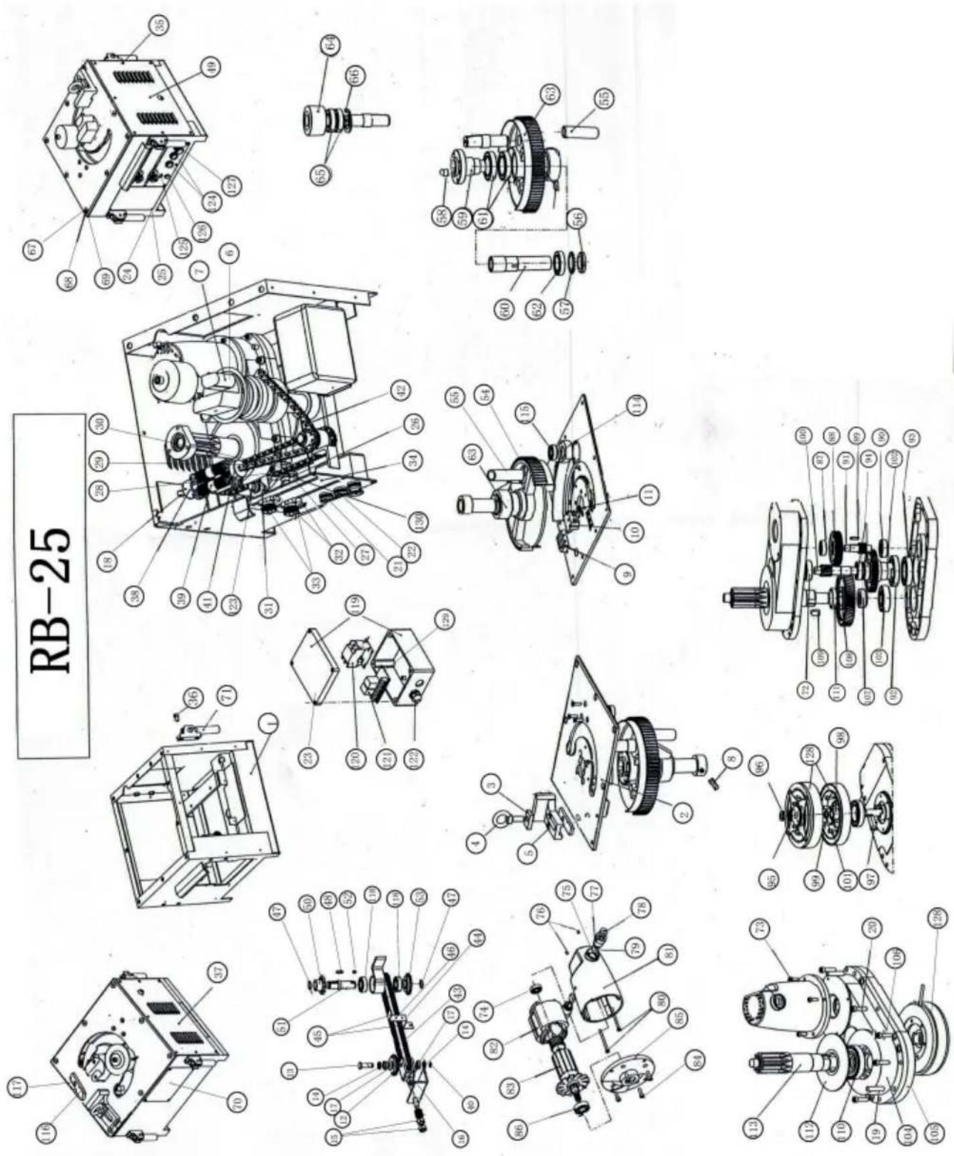
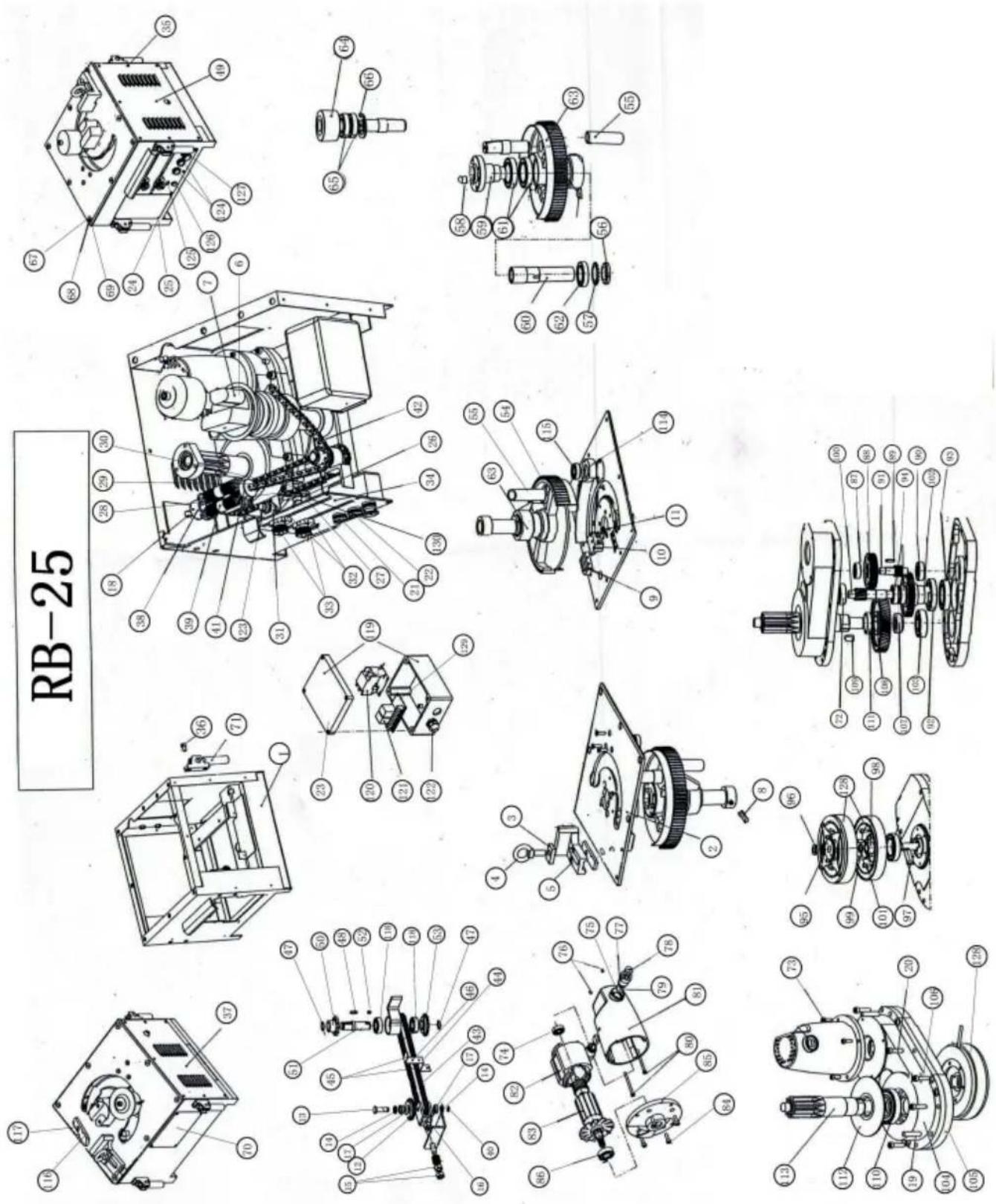
Rebar bender Parts
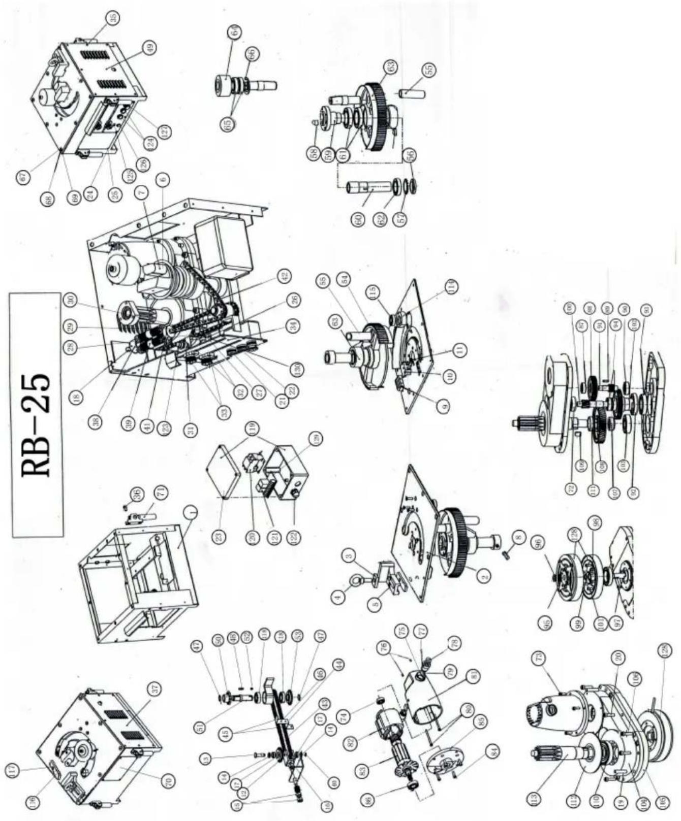
| NO. | PARTS NAME | NO. | PARTS NAME | NO. | PARTS NAME |
| 1 | Foot stand sets | 44 | stop film | 87 | 6202 bearing 15×35×11 |
| 2 | work table sets | 45 | chain connector | 88 | gear |
| 3 | fixed gasket | 46 | cup head rivetΦ3.5×4 | 89 | round head flat key |
| 4 | hexagonal screw M16×55 | 47 | shaft circlip Φ20 | 90 | 6302bearing15×42×13 |
| 5 | adjust block | 48 | round head flat key | 91 | gear shaft |
| 6 | model | 49 | right shutter | 92 | 61910 bearing 50×72×12 |
| 7 | locating shaft | 50 | chain wheel | 93 | 10008bearing40×68×9 |
| 8 | hexagon socket set screws | 51 | chain wheel shaft | 94 | 6004bearing20×42×12 |
| 9 | buffer block | 52 | round head flat key | 95 | stop washer 16 |
| 10 | stop block | 53 | chain wheel | 96 | round nut M16×1.5 |
| 11 | hexagon socket set screws | 54 | inner hexagon screw | 97 | round head flat key |
| 12 | chain wheel | 55 | leakage terminal welding sets | 98 | Needle bearing |
| 13 | pin roll | 56 | round nut M45×1.5 | 99 | bearing gasket |
| 14 | gasket 12 | 57 | stop washer Φ45 | 100 | gear shaft |
| 15 | nut M12 | 58 | round head flat key12×17 | 101 | inner hexagon screw |
| 16 | chain wheel foc stand | 59 | locating sleeve | 102 | connecting gear |
| 17 | 61901bearing12×24×6 | 60 | connect sleeve | 103 | 6305 bearing 25×62×17 |
| 18 | hexagon headed bolt | 61 | 6011 bearing 55×90×18 | 104 | gear case(up case) |
| 19 | round pin 10×3 | 62 | 6009 bearing 45×75×16 | 105 | gear case(down case) |
| 20 | inner hexagon screwM8×35 | 63 | big gear component | 106 | inner hexagon screw |
| 21 | cord arma | 64 | roll wheel | 107 | washer |
| 22 | cord arma | 65 | 6207 bearing 35×72×17 | 108 | gear |
| 23 | electrical housing | 66 | hole collar Φ72 | 109 | round head flat key |
| 24 | gasket | 67 | chamfer head screw M10×25 | 110 | 6208bearing40×80×18 |
| 25 | pan head screw M4×7 | 68 | spring washerΦ10 | 111 | washer |
| 26 | Down sensor holder | 69 | nut M10 | 112 | housing |
| 27 | nut M4 | 70 | air door plate | 113 | gear shaft |
| 28 | chamfer head screw | 71 | handle rivet sets | 114 | washer |
| 29 | nut bolt | 72 | 6303 bearing 17×47×14 | 115 | 6204bearing20×47×14 |
| 30 | nut M5 | 73 | inner hexagon screw | 116 | gasket |
| 31 | up sensor holder | 74 | 6200bearing 10×30×9 | 117 | inner hexagon screw |
| 32 | cord holder | 75 | carbon holder's washer | 118 | 6004 bearing |
| 33 | hand wheel | 76 | hexagon socket set screws | 119 | electric box |
| 34 | panel | 77 | carbon holder sets | 120 | contactor |
| 35 | pan head screv | 78 | carbon holder cap | 121 | relay |
| 36 | inner hexagon screw | 79 | carbon brush sets | 122 | water joint |
| 37 | left shutter | 80 | inner hexagon screw | 123 | sensor |
| 38 | tension spring holder | 81 | Motor housing | 124 | navitage plug |
| 39 | tension spring | 82 | stator components | 125 | indicator lamp |
| 40 | splitpinΦ3.2×16 | 83 | rotor components | 126 | jogging switch |
| 41 | tension spring holder | 84 | inner hexagon screw | 127 | emergency switch |
| 42 | chain 08B-1-35 | 85 | motor end housing | 128 | magnetic clutch |
| 43 | chain 06B-1-T6 | 86 | 6203 bearing 17×40×12 | ||
2.Means of operation
2.1 Using methods
① When the power line connection to the 110V/220V power source the power indicator light shone on namely mean of the machine open preparation finishes may go on the normal work.
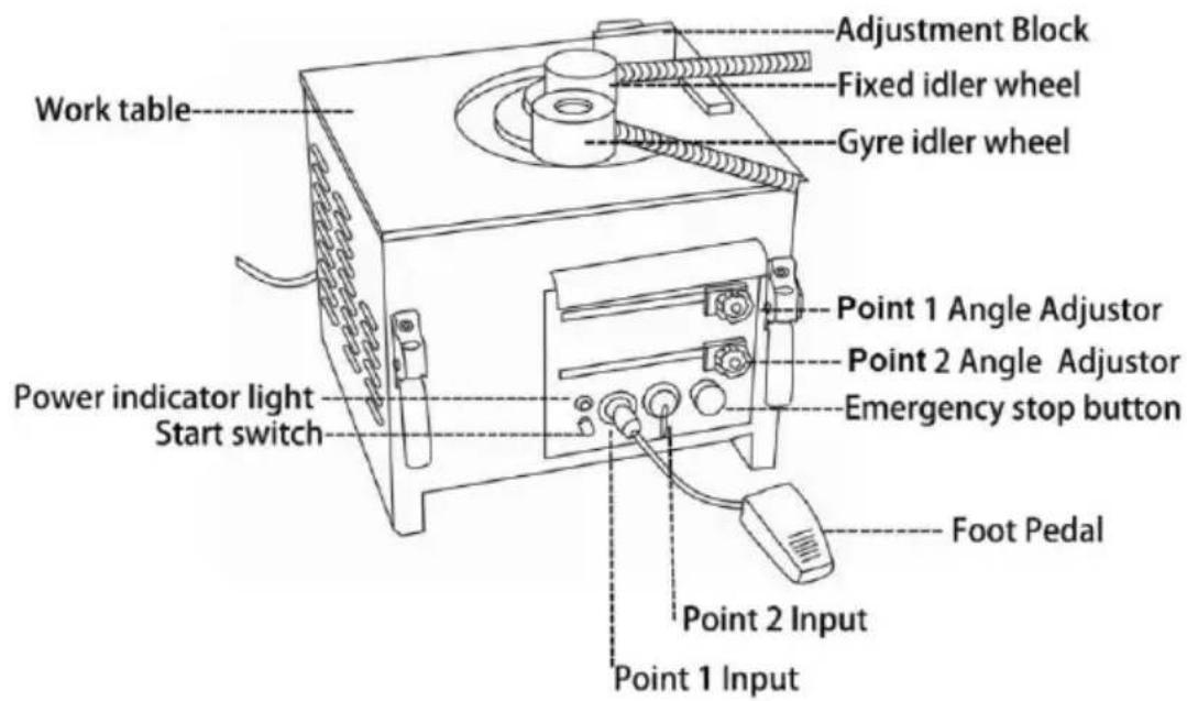
② The fixed idler wheel, the move idler wheel and the steel bar ac block's spacing needs to make the corresponding adjustment according the specification of the steel bar.
③ The foot switch connection to point1,2 will make more convenient on work.
Point 1, connect to work - angle set by is point 1, press the STAR
or point1foot pedal switch control to operation.
Point 2, connect to work, The angle set by is point 2, through the foot control operation, this time the point1 angle set by handle must establish with point 2 in the same level angle or is bigger than the point 1; while also after the angle handle setting must fix well the handle nut when the machine operation will become loose.
④ Adjust the angle that you need by through move Left or right, at adjustment is set accurately, assure that angle setting handle is fixed
⑤The operator must stand outside of the rebar bender operation's direction.
⑥ when press the starting switch or the foot switch will bend the right angle which you have set
⑦when you find some abnormal during the operation you must press emergency stopped to closes down the machine'operation.
⑧sure to remember, when bending processing, the angle of point 1 is larger than point 2, otherwise the machine cannot the normal operation (This is for RB-25 AND RBC-25, RB-32 AND RBC-32 is no problem
⑨ under situation of use foot switch beyond control machine'operation when please through press nearby power light's hand switch test mac whether to revolve judges the foot switch whether to present the breakdown.
Note: ① when press the emergency switch to run the machine, the ridler wheel will return to its position.
② under the work situation of point 2 bending, the point 1 handle'p must be keep the same level angle with point 2 or to set smaller in angle 5 degrees than the point 1 and then fix the angle handle, so to occure the electrical or the machine misoperation.
※Matching of different wheel(RB-25 / RBC-25):
| Rebar specification | Fixed idler wheel | Gyre idler wheel | Contemporary bending capacity |
| ∅22- ∅25 | ∅78 | ∅94 | 1 pcs |
| ∅16- ∅20 | ∅78 | ∅94 | 1-2 pcs |
| ∅10- ∅13 | ∅78 | ∅94 | 4-5 pcs |
| ∅6- ∅13 | module | ∅94 | 3-6 pcs |
| Special situation | Possible customize | Possible customize |
2.2.Attention items
① Must according to Contemporary bending capacity to use this process surpasses easily to cause this product breakdown.
② when go on steel bar bending work, special attention to avoid inj finger and so on safety incident.
③ according to the different hardness of reinforced material, special attention should be paid to avoid the fragrance which may lead to sa incidents such as wounding.
④. please do not operate until you confirm no person and object in the reinforced bending radius.
⑤.the product is electric functional machinery.as encountered by rain or water lead to leakage,it must be covered with waterproof membrane at use.
⑥ assure the stationary ring bolt is fixed when transit or move the machine.
⑦,when operating under point 2,fix angle of point 2 same as or no than point 1 of 5 degree,to ensure that under the condition when ex shock attacks the machine itself will not move to left and right to op the machine.
⑧.make sure the stationary ring bolt is fixed when transit or move the bender.chains must be inserted into the safety pin to pretend the ber from shaking or waving in transit.when move the bender by fixing handle ,4bolts can not loose ,then move the bender together by 4 ha
⑨ prohibit to use idler wheel items
If marks according to below (X) the method operation troughing of hoop will burst easily. Records the proper operation sincerely!
3. Environment:
Please use it under these kinds of the environment conditions.
| Environment | Environment temperature | -10°C~45°C(does not ice up |
| Environment humidity | Below 90%RH (does not congeal dew) | |
| Storage temperature | -20°C~+65°C | |
| Environment | In room (non-corrosiveness gas, flammable gas, oil mi and so on) | |
| Altitude above sea level | Below elevation 1000m |
4. Operation
4.1 Operation position
After installed the equipment, the operator can operate the equipment stand on the about 0.5m before operation panel
Notice
Do not use your hand to touch all the running parts when the equipment running in case to accident to happened.
After adjust the quantity to remember lock the nut.
If have abnormal during the running should to stop the working.
When the container is big the diameter of the filling mouth should no small in case to protect the filling mouth from damage when filling the pressure is too big.
4.2 Emergency Stop
This machine install one emergency stop button so once you press it machine will stop wholly. When there are emergency things happen p press this button.
4.3 Power
110V OR 220V single phase power supply only. The power line should follow the demand as mentioned in safety rules.
4.4 Control panel
1 indicating light: when connecting the power supply, the light should on.
2 manual switch: if the foot switch could not control the machine open replace foot switch 1 by the manual switch near the power light.
3 foot switch 1: press foot switch 1 to complete the operation of an settled by the “1 point” angle adjustor.
4 foot switch 2: press foot switch 2 to complete the operation of an settled by the “2 point” angle adjustor.
5 emergency stop switch: during the operation, if there is any trouble release the button and stop all actions.
6. angle 1: adjust the bended angle by the "1 point" adjustor (corresponding with foot switch 1)
7. angle 2: adjust the bended angle by the "2 point" adjustor (corresponding with foot switch 2)
8. Before bending, please note the angle setting of "1 point" must be bigger than the "2 point", or the machine can't work. This is for RB-2 AND RBC-25, RB-32 AND RBC-32 is no problem.
4.5 Operate process
1). please connect the power wire to 110V/220V electric and see the indicator light lights up. It means the bender is ready to work.
2).please choose the correct size fixed idler wheel and correct size id wheel according to the rebar diameter.
3). Please Connect pedal switches with 1 point and 2 point hole tightly.
4). The 1 point angle setting adjustor is for setting the foot switch connecting with 1 point hole. For example to bend 180 degree by foot switch 1, you set the angle 180 degree by the 1 point adjustor, then y touch the foot switch 1 to bend the rebar 180 degree.
5). The 2 point angle setting adjustor is for setting the foot switch connecting with 2 point hole. For example to bend 90 degree by foot 2, you set the angle 90 degree by the 2 point adjustor, then you touch foot switch 2 to bend the rebar 90 degree.
6).please note the angle setting of "1 point" must be bigger than the point",or the machine can't work.please see the below two pictures.
7). Fix the angle adjustor by moving to left and right accordingly.
8).Operator should work on the outside of the rebar's bending direction
9). Rebar will be bent to set angle when pressing the start switch or switch.
Attention: In order to work precisely, PIs set at point 1 when the be angle is large(90°), and set at point 2 when the bending angle is sr (135°)
Note :
① follow the processing capacity while use the product is a must, s the product easily lead to failure.
②operation gripping bending reinforced material should pay special attention to safety incidents such as bumping fingers.
③ According to the different hardness of reinforced material, special attention should be paid to the fracture which may lead to safety inc such as wounding.
④ Please do not operate until you confirm no person and object in reinforced bending radius.
⑤ the product is electrical functioning machinery. As encountered by rain or water leading to leakage, it must be covered with waterproof membrane after use.
4.6 Movement
- Move the bender after making sure the handle fixing bolt is tight.
- Make sure the stationary ring bolt is fixed when transit or move to gender.
- Chains must be inserted into the safety pin to pretend the bender shaking or waving in the transit.
- When move the bender by fixing handle, 4 bolts can not loose or damaged. Move the bender together by 4 handles.
5. Maintenance
5.1 Check and Change
①Change the carbon brush --- The power must be cut off. If the r stops operating during the process, please confirm the wearing and test intensity of the carbon brush. The carbon brush that electric machiner uses belongs to consumables. If the carbon brush is used beyond the restraining line of the wearing and tearing, the electric machinery will subside, even stop running. Then turn off the machine and resume it machine shuts down automatically after transient running, it proves to necessary to change the carbon brush. Please do use the machine at the change of the carbon brush as the continuing use accelerates we and tearing of the commutator which leading to the damage of the coil.
②Means of changing:
Open the upper brush cap with a screwdriver so that the carbon bru be taken out in the machine.
Please use the attaching brush while purchasing the machine to clear internal centre axle and fixed gyro wheel before changing and using.
5.2. Lubrication:
5.2.1. Cycle:
The lubrication should be done by the personnel regularly and also c maintained during the time that not be used.
PLS put the lubrication every week.
5.2.2. Oil
It adopts the common lithium grease; do not use the different lubrication the same time, if you choose one because it will influence the life's
5.2.3. Cleaning the oil mouth
Before put the lubrication grease should clean the oil mouth and do remember to wipe off the remaining.
5.3 Check and maintain
Check the bolts and nuts of every position, if they become flexible. In moist season or after rainy days, the rain-proof ventilate must be to dry. In the case of heavy power shock when turn the gyro wheel to the location, round it tight after adjusting the unclamp, bludgonned
into the very slow state.
Panel indicator lamp on means the machine is turned round and plan. Check the power and cable if not bright when putting through the pc rear board indicator lamp.
Indicator lamp shows the panel, if it is unable to start the machine press START switch --- Please confirm the tearing state of wearing a carbon brush.
In addition, please consult each branch and after sale service centre general headquarters for other items.
6. Electrical safety
6.1. Safety rules of electrical system
-
Only personnel who are properly trained and have adequate knowledge and skill should undertake all electrical troubleshooting and repair.
-
Do not alter or bypass protective interlocks.
-
Before starting, read and observe all warning labels
-
When trouble shooting make sure the power source has been cut-and main switch has been locked.
-
Take extra precautions in damp areas area to protect you from accidental grounding.
-
Before applying power to any equipment it must be established, w a doubt, that all persons are clear.
-
Do not open the electrical control panel unless it is necessary to the electrical equipment.
-
Do not alter the electrical circuits unless authorized to do by the manufacturer
-
When replacing electrical components, make sure they conform to manufacturers specifications, including proper color-coding.
-
Do not wear metal glasses, metallic necklaces or chains while work on any electrical equipment.
Also do not wear any ring, watch or bracelet while operating electrical equipment.
Additional instructions for rebar cutter (Rebar cutter and bender Model)
General Safety Precautions
Usage
Use rebar cutters on concrete re-forcing bars only.
Restrict use to designated materials
There is always a chance that the cut end may shoot out, especially than 30cm in length. Exceeding designated material specifications great increases this risk and will also damage the tool. Do not attempt to rebars. Harder, thicker or thinner than those specified.
Use eye protection
Wear safety goggles, safety glassed with side shields or a face shield when using cutter.
Provide safety barriers
Erect safety screens to protect co-workers from possible flying ends. If safety screen under the rebar when working in high places.
Exercise proper control
Hold cutter firmly and maintain proper footing and balance. Do not over-reach when working in high place, secure cutter to scaffolding safety rope. Check that power cord is not fouled and keep cord awa sharp edges and heat. Check that all adjusting wrenches have been removed before using cutter.
Guard Against electric shock
To avoid possible electric shock, do not handle cutter with wet hands use cutter in the rain or damp places. Be aware of all power lines,
circuits and other hazards that may be contacted , especially those thbelow the surface or otherwise hidden from view .
Unplug tool
Disconnect cutter from outlet when not in use and before cleaning, adjusting or servicing. Do not disconnect plug from outlet by pulling the cord. Always check that the switch lock if OFF before plugging in.
Beware of environment
Do not use cutter in the presence of flammable materials (e.g. Paint, thinner, petroleum products, adhesives).
Do not use cutter in a possibly lighted and clear of obstructions. Op should at all times have an unobstructed view of the cutter, rebar and surrounding area.
Wear proper apparel
Do not wear loose clothes, dangling objects or jewellery. Restrain long. The use of a safety-helmet and rubber soled boots is recommended safety gloves are worn, be especially careful that gloves does not get caught in moving parts.
Keep visitors aways
Keep all visitors at a safe distance from the work area for their own protection and to prevent distraction of the operator.
Maintain cutter with care
Inspect cutter before each application. Faulty or loose cutter blocks cc result in personal injury . Keep handle dry, clean and free from oil a grease. Keep housing and piston free of dirt and iron filings. Check screws or bolts are loose or missing. Following instruction for maintenance . Inspect switch, cord,plug and any extension cable at re intervals.
Store carefully
When not in use, store cutter and accessories in dry place where th be accessed by unauthorized person.
Operating Instructions
Caution: Indicates hazard that could result in minor personal injury or product damage.
Care: Indicates hazard that will result in product damage.
Pre-use checks
- Check oil level.
- Check condition of cutter blocks and tightness of cutter block bolts.
Caution: Using loose or cracked cutter blocks may result in injury to operators as well as damage to unit. - Check that the power source is appropriate for the cutter.
4.Care : If voltage is too high , the motor will burn out. If the voltalow, insufficient power will be generated. Never use DC current. - Check that power supply is properly earthed.
- Caution: Failure to earth power supply may result in electric shock operator.
- Check that cord is undamaged and that plug is not loose.
Caution: Cut or abraded covering could result in a short and electric to operator.
Warm-up
In cold weather , warm up unit for 30-60 seconds so that the hydra reaches the proper viscosity. Pull trigger -switch to extend piston and release when it has reached its full stroke, Repeat 15-20 times.
Stopper adjustment
The adjustable stopper function to maintain the rebar in the correct p during cutting and must be properly set for each size of rebar before
making a cut.
·Screw in stopper to provide sufficient clearance for rebar.
- Insert rebar fully into U-shaped support. Make sure that rebar is rest the base of the stopper.
- Keeping rebar at right angels (90°) to front cutter block, screw out s until it is just touching the rebar. Once set, the stoooper needs no fu adjustment while cutting rebar of the same diameter, but must be re-a different size rebar.
Caution: Failure to correctly set the stopper will result in excessive w cutter block and may cause cut end to fly out.
Cutting
- Insert rebar between stopper and front cutter block, making sure that properly seated in U-shaped support.
- Pull trigger -switch and keep depressed while piston advances and is cut. ( If switch is released at an intermediate point, piston will stop
- When cut is completed, release switch. Piston retracts automatically.
(Note that switch can't be re-activated until piston has fully retracted.)
Points of attention
- Be especially careful when cutting off short lengths (30cm or less) cut end tends to fly out.
!Caution : Flying ends are a hazard to all personnel in the vicinity. safety screens.
- Do not cover air vents.
Care: If events are covered, motor will overheat and may burn out.
- If hydraulic oil exceeds 70^ (158 F) in temperature, power will drop. Allow until to cool before resuming operation. (Be particularly careful in summer, when the aluminum pump case heats up quicker.)
- If a drop in power is observed and motor is unusually hot, check brush.
- If piston should ever fail to retract completely, push rear cutter bloc backwards to manually retract piton.
Caution: Use a rebar or flat metal bar for this purpose. Never push block with any part of the hand, even if gloved.
Once piston has been retracted, pull trigger-switch long enough to p advance piston. Unplug unit. And check piston and housing for accumulated dust iron filings that may be jamming the piston. After cleaning, piston still does not automatically retract when fully extended piston itself may be damaged. Return the unit to an authorized agent repair.
Maintenance
Cutter blocks
Before using, always check that the two bolts on each cutter block a properly tightened. Using a loose block will result in damage to block housing. Also check condition of cutter blocks. If either cutting edge i or chipped, remove retaining bolts and rotate both blocks so that two edges come into use. Replace and tighten bolts (each block has four cutting edges)
When all four cutting edges have been used or if either block is cra otherwise damaged, replace both block.
Caution: A loose or cracked block may result in injury to operator.
Cleaning
Cleaning cutter after use.
Caution: Wear gloves to protect hands from metal splinters. Do not use air-gun, blasting with air can cause metal filing and/or dust to get into and respiratory system.
- Disconnect unit.
- Wipe or brush away all dirt and metal filings. Pay particular attention the lower half of the piston, where dirt is more easily accumulated.
Oil-level check
As the cutters are hydraulically operated, the oil level must be checked frequent intervals, preferably every day. Failure to maintain the oil at proper level results in a drop in pressure and loss of cutting power.
Caution: Hydraulic oil is highly flammable. Keep away from sparks ar naked flame. Do not smoke.
Caution: Hydraulic oil may cause inflammation of the eyes and skin. ingested, it will cause diarrhoea and vomiting.
In case of eye contact, rinse in clean water for at least 15 minutes consult a physician. In case of skin contact, wash thoroughly with soap water.
In case of ingestion, consult a physician immediately. Do not deliberate induce vomiting.
- Oil should be warm but not hot. Warm up unit if cold.
- Adjust stopper and make three or four cuts, noting exactly at what the rebar is actually breaking.
- Pinch a short piece of rebar, stopping just before it breaks off. Unp from power source.
- With partially severed rebar in place, turn unit over so that oil-plug uppermost. (If unit is hot, allow to cool down.)
- Remove oil-plug and seal-washer (packing)
Caution: Never remove oil-plug when unit is hot or oil will spurt out.
-
check that oil is level with bottom of plug hole. (i.e. That pump can to the brim). If oil level is too low, top up with 20-weight hydraulic anti-foam and anti-abrasion properties. (ISO viscosity grade VG46. E.g. Shell oil tellus 46, mobil oil DTE-25 OR Esso uni power SQ46.)
-
After topping up, extract air from system. Gently tilt cutter lengthwise return it to a level position. Top up again and tilt in the opposite di Repeat this process until all air has been extracted.
Care: Cutter can't function properly if oil contains air bubbles.
- Replace seal washer (packing) and plug. Connect cutter to power so and completely serve rebar.
Oil change
- The hydraulic oil should be changed at least once a year. Sooner appears dirty.
- Unplug unit from power source. Remove oil plug and packing. Turn over and drain oil into a suitable receptacle. When oil ceases to draw tilt unit to rear so that oil trapped in the piston housing can run out housing is empty, tilt unit in the opposite direction to empty the residue the pump case.
- With drain-hole uppermost, slowly fill the unit with fresh oil. Replace and lightly tighten. Connect unit to power source and advance piston three times. Unplug unit and remove oil-plug. Top up oil level and plug.
- Finally follow procedure for oil level check.
Note: Dispose of hydraulic oil in accordance with local regulations. Do pour into the sea, river, lake or drains.
Bolt tightness
Once a week or after every 500 cuts, check the tightness of all bolts especially those securing the housing to the cylinder. Loose bolts will in a loss of power.
Carbon brushes
Inspect the two carbon brushes at least once every two months. (nor brush life is 200 hours.)
Care: Worn brushes will result in power loss, cause the motor to run and irreparably damage the armature's commutator.
1.Disconnect unit
2. Unscrew both brush caps and pull out carbon brushes.
3. Replace brushes if less than 6 cm in length.
Manufacturer: Shanghaimuxinmuyeyouxiangongsi
Address: Shuangchenglu 803nong11hao1602A-1609shi, baoshanqu, shanghai 200000 CN.
Imported to AUS: SIHAO PTY LTD. 1 ROKEVA STREETEASTWOOD NSW 2122 Australia
Imported to USA: Sanven Technology Ltd. Suite 250, 9166 Anaheim Place, Rancho Cucamonga, CA 91730
| UK | REP |
YH CONSULTING LIMITED. C/O YH Consultin Limited Office 147, Centurion House, London Road, Staines-upon-Thames, Surrey, TW18 4A>
| EC | REP |
Technical Support and E-Warranty Certificate
www.vevor.com/support
VEVOR®
TOUGH TOOLS, HALF PRICE
natural_image
Collection of industrial machinery components including a rotary switch, coiled pipes, and a machine with control panel (no visible text or labels)BESOIN D'AIDE? CONTACTEZ-NOUS!
Eviter les dégâts

Danger
Transport et installation

Attention

YH CONSULTING LIMITÉE. C/O YH Consulting Limited Bureau 147, Centurion House, London Road, Staines-upon-Thames, Surrey, TW18 4AX
| REPRÉSENTANT CE |
E-CrossStu GmbH
Mainzer Landstr.69,
natural_image
Collection of industrial machinery components including a rotary switch, coiled pipes, and pressure vessels (no visible text or labels)1. KENNEN SIE IHRE MASCHINE.

YH CONSULTING LIMITED. C/O YH Consulting Limited Office 147, Centurion House, London Road, Staines-upon-Thames, Surrey, TW18 4AX

www.vevor.com/support
VEVOR®
TOUGH TOOLS, HALF PRICE
natural_image
Collection of industrial machinery components including a rotary switch, coiled pipes, and a machine with control panel (no visible text or symbols)HO BISOGNO DI AIUTO? CONTATTACI!
Evitare il danno

Pericolo

Shell oil tellus 46, mobil oil DTE-25 O Esso uni power SQ46.)
Importato in AUS: SIHAO PTY LTD. 1 ROKEVA STREETEASTWOOD NSW 2122
Australia
YH CONSULENZA LIMITATA. C/O YH Consulting Limited
Office 147, Centurion House, London Road, Stainesupon-Thames, Surrey, TW18 4AX
| REP.CE |
E-CrossStu GmbH
Mainzer Landstr.69,
elettronica www.vevor.com/support
VEVOR®
TOUGH TOOLS, HALF PRICE
natural_image
Collection of industrial machinery components including a rotary switch, coiled pipes, and a machine with control panel (no visible text or labels)evitar el daño

Peligro
YH CONSULTING LIMITADO. C/O YH Consulting Limited Oficina 147, Centurion House, London Road, Staines-upon-Thames, Surrey, TW18 4AX

E-CrossStu GmbH
Mainzer Landstr.69,
natural_image
Collection of industrial machinery components including a rotary switch, coiled pipes, and a machine with control panel (no visible text or symbols)POTRZEBUJE POMOCY? SKONTAKTUJ SIĘ Z NAMI!
Unikaj uszkodzeń

Niebezpieczeństwo
ODPOWIEDZIALNOŚCIĄ. C/O YH Consulting Limited Office
147, Centurion House, London Road, Staines-upon-Thames, Surrey, TW18 4
E-CrossStu GmbH
Mainzer Landstr.69,
60329 Frankfurt nad Menem.
VEVOR®
TOUGH TOOLS, HALF PRICE
www.vevor.com/support
VEVOR®
TOUGH TOOLS, HALF PRICE
Technische ondersteuning en e-garantiecertificaat www.vevor.com/support
BENCHTOP HYDRAULISCH
WAPENING BUIGER
MODEL:RBC-25/RB-25
natural_image
Collection of industrial machinery components including a rotary switch, coiled pipes, and a machine with control panel (no visible text or symbols)HULP NODIG? NEEM CONTACT MET ONS OP!
Vermijd de schade

Gevaar

YH CONSULTING LIMITED. C/O YH Consulting Limited Office 147, Centurion House, London Road, Staines-upon-Thames, Surrey, TW18 4AX

garantiecertificaat www.vevor.com/support
VEVOR®
TOUGH TOOLS, HALF PRICE
natural_image
Collection of industrial machinery components including a rotary switch, coiled pipes, and a machine with control panel (no visible text or symbols)BEHÖVS HJÄLP? KONTAKTA OSS!
Undvik skadan

Fara

YH CONSULTING LIMITED. C/O YH Consulting Limited Office 147, Centurion House, London Road, Staines-upon-Thames, Surrey, TW18 4AX
| EC | REP |
www.vevor.com/support