
HMR1200 - Electric trowel Vevor - Free user manual and instructions
Find the device manual for free HMR1200 Vevor in PDF.

User questions about HMR1200 Vevor
0 question about this device. Answer the ones you know or ask your own.
Ask a new question about this device
Download the instructions for your Electric trowel in PDF format for free! Find your manual HMR1200 - Vevor and take your electronic device back in hand. On this page are published all the documents necessary for the use of your device. HMR1200 by Vevor.
USER MANUAL HMR1200 Vevor
Technical Support and E-Warranty Certificate www.vevor.com/support
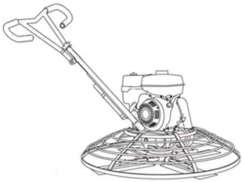
POWER TROWEL
MODEL:HMR950、HMR1200
We continue to be committed to provide you tools with competitive price. "Save Half", "Half Price" or any other similar expressions used by us only represent of savings you might benefit from buying certain tools with us compared top brands and does not necessarily mean to cover all categories of tools offered are kindly reminded to verify carefully when you are placing an order with us actually saving half in comparison with the top major brands.
MODEL:HMR950、HMR1200
natural_image
Line drawing of a cleaning lathe machine with a circular base (no text or symbols)NEED HELP? CONTACT US!
Have product questions? Need technical support? Please feel fr contact us:
Technical Support and E-Warranty Certificate www.vevor.com/support
This is the original instruction, please read all manual instruction carefully before operating. VEVOR reserves a clear interpretation user manual. The appearance of the product shall be subject to product you received. Please forgive us that we won't inform you there are any technology or software updates on our product.
IMPORTANT SAFEGUARDS

WARNING: Read and understand this entire manual before operating or servicing this product. Failure to follow these warnings and instructions can cause personal injury or damage to valuable property.
1. Safety Information
1.1 Laws Pertaining to Spark Arresters
Notice: State Health Safety Codes and Public Resources Codes specif that in certain locations spark arresters be used on internal combustio engines that use hydrocarbon fuels. A spark arrester is a device desi to prevent accidental discharge of sparks or flames from the engine exhaust. Spark arresters are qualified and rated by the United States Forest Service for this purpose.
In order to comply with local laws regarding spark arresters, consult the engine distributor or the local Health and Safety Administrator.
1.2 Operating Safety

WARNING
Familiarity and proper training are required for the safe operation of equipment! Equipment operated improperly or by untrained personnel can be dangerous! Read the operating instructions contained in both this manual and the engine manual and familiarize yourself with the location and proper use of all controls. Inexperienced operators should receive instruction from someone familiar with the equipment before being allowed to operate the machine.
- NEVER allow anyone to operate this equipment without proper traini. People operating this equipment must be familiar with the risks and hazards associated with it.
- NEVER touch the engine or muffler while the engine is on or imm after it has been turned off. These areas get hot and may cause but
- NEVER use accessories or attachments that are not recommended
Tomahawk Power. Damage to equipment and injury to the user may
- NEVER leave machine running unattended.
- ALWAYS be sure operator is familiar with proper safety precautions operation techniques before using machine.
- ALWAYS wear ANSI Z87.1-approved safety goggles or safety glasses with side shields,or when needed, a face shield. Use a dust mask in work conditions. Also use non-skid safety shoes, hardhat, gloves, dust collection systems, and hearing protection when appropriate. This applies to all persons in the work area.
- ALWAYS close fuel valve on engines equipped with one when made not being operated.
- ALWAYS store equipment properly when it is not being used. Equip should be stored in a clean, dry location out of the reach of children
- ALWAYS operate machine with all safety devices and guards in place and in working order. DO NOT modify or remove safety devices. DO operate machine if any safety devices or guards are missing or inoper
- ALWAYS read, understand, and follow procedures in Operator's Man before attempting to operate equipment.
1.3 Safety while using Combustion Engines

DANGER
Internal combustion engines present special hazards during operation and fueling! Read and follow warning instructions in engine owner's manual and safety guidelines below. Failure to follow warnings and DANGER safety guidelines could result in severe
injury or death.
- DO NOT run machine indoors or in an enclosed area such as trenches unless there is adequate ventilation, through such items exhaust fans or hoses are provided. Gasoline exhaust from the engine contains poisonous carbon monoxide gas; exposure to carbon monoxide can cause loss of consciousness and may lead
death.
• DO NOT smoke while operating machine.
• DO NOT smoke when refueling engine.
• DO NOT refuel hot or running engine.
• DO NOT refuel engine near open flame.
• DO NOT spill fuel when refueling engine.
• DO NOT run engine near open flames.
- ALWAYS refill fuel tank in well-ventilated area.
- ALWAYS replace fuel tank cap after refueling.
- ALWAYS check fuel lines and fuel tank for leaks and cracks by starting engine.
• DO NOT run machine if fuel leaks are present or fuel lines are
1.4 Service Safety

WARNING
Poorly maintained equipment can become a safety hazard! In order for equipment to operate safely and properly over a long period of time, periodic
maintenance and occasional repairs are necessary.
- DO NOT attempt to clean or service machine while it is running. Rotating parts can cause severe injury.
- DO NOT crank a flooded engine with the spark plug removed gasoline-powered engines. Fuel trapped in the cylinder will squirt the spark plug opening.
- DO NOT test for spark on gasoline-powered engines, if engine flooded or the smell of gasoline is present. A stray spark could fumes.
- DO NOT use gasoline or other types of fuels or flammable sol to clean parts, especially in enclosed areas. Fumes from fuels an solvents can become explosive.
-
ALWAYS keep area around muffler free of debris such as leave paper, cartons, etc. A hot muffler could ignite them, starting a fire
-
ALWAYS replace worn or damaged components with spare parts designed and recommended by Tomahawk Power.
- ALWAYS disconnect spark plug on machines equipped with gasoline engines, before servicing, to avoid accidental start-up.
- ALWAYS keep machine clean and labels legible. Replace all mis and hard-to-read labels. Labels provide important operating instructions and warn of dangers and hazards.
- ALWAYS check for damaged parts before each use. Carefully cl that the trowel will operate properly and perform its intended fun Replace damaged or worn parts immediately. Never operate the trowel with a damaged part.
- ALWAYS inspect the screed prior to placing in storage and before-use. Store the trowel in a dry, secure place out of the reach children when not in use.
- ALWAYS use only accessories that are recommended by the manufacturer for use with the trowel. Accessories that may be suitable for one trowel may create a risk of injury when used w screed equipment.
- ALWAYS keep blades clean when not in use and guards in place in working order.
2 Product information
2.1 Intended Use
Leave laborious hand-finishing tasks in the past with the Tomahawk F Trowels! Densify concrete floors with ease for your ideal finishing result on projects including driveways, basements, and commercial/industrial jobs.
2.2 Trowel Familiarization
VEVOR's Power Trowels are designed for the floating and finishing of concrete slabs. Analyze your trowel and take notice of each component engine, blades, quick pitch control, air cleaner, centrifugal stop switch, clutch and pulley system. Be sure that there is always oil in the eng
2.3 Safety
Before using your power trowel, read all of the safety instructions car Safety instructions are available throughout this manual and on the equipment. Safety information should remain in good, readable condition Operators must be well trained on the operations and maintenance of trowel.
Before starting, test the trowel on a flat, watered down section of fin concrete. Test on a section that is free of any debris and other obje The trial test run will increase operator confidence, while helping family yourself with the trowel's controls. In addition, this will help operators understand how the power trowel functions under real conditions.
2.4 Engine
VEVOR's Power Trowels are powered by Kohler Engines. Refer to the engine owner's manual for instructions regarding the operation and maintenance of your engine. The engine manual is included with your trowel.
2.5 Drive System
The power is transferred from the engine to the gearbox input shaft V-belt pulley drive
system. The pulley engages using either a centrifugal or manual clutch. Refer to the Parts section of this manual for more information.
2.6 Gearbox
The gearbox is located beneath the engine and transfers power to the or spiderbox assembly. The gearbox controls the rotational speed of trowel and is equipped with two shafts (input and output).
2.7 Spiderbox
The vertical output shaft of the gearbox connects to a cast hub called spiderbox. The spiderbox has 4 arms that extend outward that are used attachment of blades or other accessories. Remember: when the gearbox output shaft rotates, so does the spiderbox assembly.
2.8 Blades
The blades of the trowel are used to finish the concrete as they rot around your given surface. This trowel includes 4 combination blades rotor. They are equally spaced in a radial pattern and attached to th
vertical rotating shaft by means of the spider assembly.
2.9 Centrifugal Clutch
In the event of a trowel runaway condition (the operator releases the handle), the centrifugal clutch will stop the engine and bring the trowel complete stop.
2.10 Training
For proper training education, refer to the “TRAINING CHECKLIST” section located in the back of this manual. This checklist contains an outline for an experienced operators to provide training to a new ope
3. Technical Specifications
Trowel
| Model | HMR950 | HMR1200 |
| Engine | CH260 | CH440 |
| Number of blades | 4 | 4 |
| Disc diameter | 38in | 46in |
| Optimum blade Angle adjustment(°) | 0-15 | 0-15 |
Engine
| Model | CH440 |
| Type | 4-stroke,overheard camshaft,1 cylinde |
| HP | 14 |
| Transmission system | Worm gear and worm |
| Fuel consumption (g/kWh) | 374 |
| Maximum speed (r/min) | 2800 |
4 User guide
4.1 Express setup
 Step1:Insert the end of the har bar column into the base of trowel. Step1:Insert the end of the har bar column into the base of trowel. | 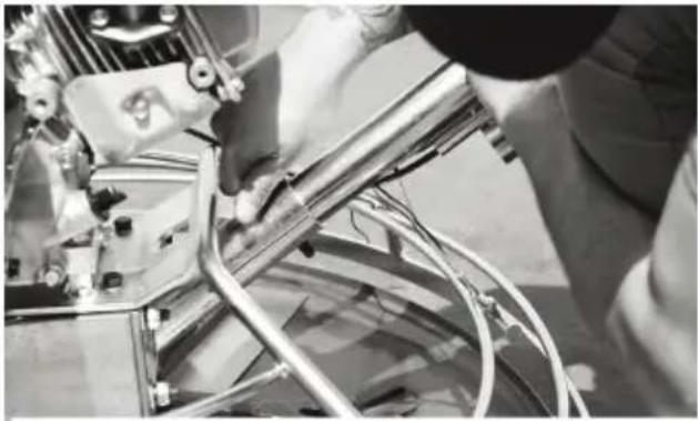 Step2:Insert the bolts and washers through the holes in handle bar - fasten with a Step2:Insert the bolts and washers through the holes in handle bar - fasten with a |
 Step3:Unscrew the nut from the and insert the pin through the of the trowel. Step3:Unscrew the nut from the and insert the pin through the of the trowel. | 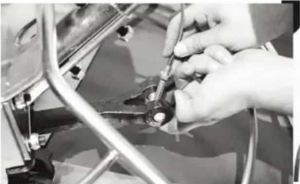 Step4:Fit the screw through the pin and fasten the nuts on the and bottom to keep it in pla Step4:Fit the screw through the pin and fasten the nuts on the and bottom to keep it in pla |
 Step5:Fit the handle bars around the eye towards the top of thandle bar column. Step5:Fit the handle bars around the eye towards the top of thandle bar column. | 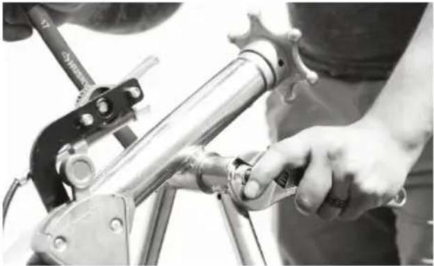 Step6:Place the bolt through the base of the handles and the fasten with a nut on the e Step6:Place the bolt through the base of the handles and the fasten with a nut on the e |
4.2 Quick start guide

natural_image
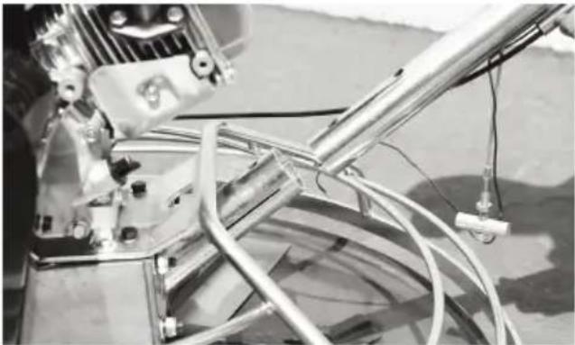
Close-up of hands operating a mechanical device with a knob and a textured cylindrical component (no visible text or symbols)Step:7 To attach the throttle ca remove the air filter and the co
natural_image
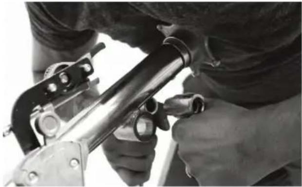
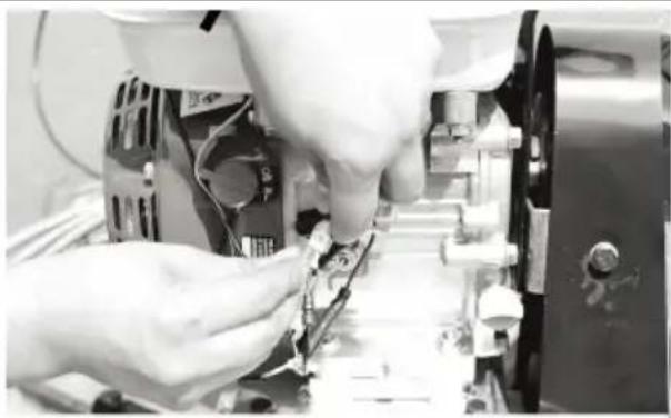
Close-up of hands working on mechanical components with no visible text or symbolsStep:8 Feed the cable through pivot nut and through the sw stop, then fasten the screw.
natural_image
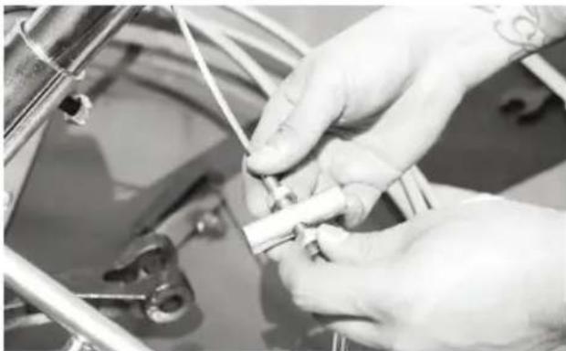
Close-up of hands assembling or repairing electronic components in a machine (no visible text or symbols)Step:9 Bring the kill switch wire the front of the engine and con it the the shut off switch.
natural_image
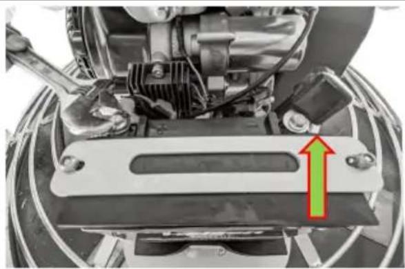
Close-up of a mechanical assembly with a green arrow pointing to a component (no visible text or symbols)Step:10 Fasten the positive (re and negative (black) engine lea to the battery.
5. Controls and Components
5.1 Handle
Includes a "starwheel" for manually adjusting blade angle .
natural_image
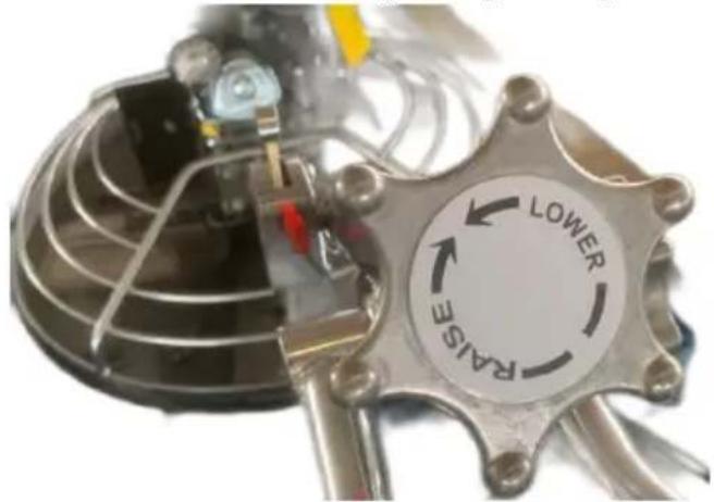
Close-up of a mechanical device with a circular indicator labeled 'LOWER' and 'FAISE', no readable text or symbols beyond the indicator.5.2 Foldable Quick Pitch Handle
Employs a lever handle to quickly adjust blade pitch. Handle folds for storage.
natural_image
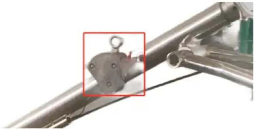
Close-up of a metallic mechanical component with a grid pattern and a red box highlighting a specific part (no text or symbols visible)5.3 Centrifugal Kill Switch
In the event the operator loses control of the trowel, this switch will shut-down the engine.
natural_image
Close-up of a metallic mechanical component with a red box highlighting a small circular feature (no text or symbols visible)5.4 Throttle Control Lever
The throttle controls the speed of the engine. Move the hand lever to the operator to increase engine speed (high), away from the operator decrease engine speed (low).

natural_image
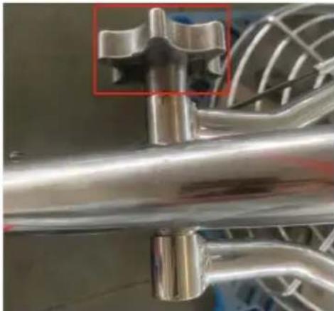
Close-up of a metal hanger with a small inset showing a mechanical component (no text or symbols visible)5.5 Bicycle Handlebars
The trowel's wider handlebars allow for higher stability, balance, and maneuverability. Replace handle grips if they become worn or damaged.
5.6 Engine
VEVOR's Trowels use Kohler engines and are backed by a 3-year er warranty for reliable service.
5.7 Blade Pitch Control
Adjust the trowel's steel blades from 0-15 degrees to achieve a matte gloss, or gleaming finish.
5.8 Guard Ring
NEVER put hands and feet inside the guard ring.
5.9 Trowel Arm
Provides attachment points for the blades. If the blades show uneven patterns or if blades wear out faster than others, the trowel arm may to be replaced.
5.10 Blades
This trowel is equipped with 4 combo hardened, steel blades designed both float and finish operations. These blades are interchangeable with most manufacturers.
5.11 V-Belt Cover
Remove this cover to gain access to the V-Belt. NEVER operate the with this cover removed.
5.12 Handle
Loosen to fold handle.
5.2 Additional Components
5.2.1 Stabilizer Ring
The stabilizer ring reduces the vibrations from the trowel arm and kee balanced.
5.2.2 Float Pan
Designed to clip onto the combo blades, the float pan works to break high spots, bringing mortar to the surface and producing a uniform ar
level slab.
5.2.3 Auxiliary Lifting Tube
Use this tube to lift the trowel onto a slab. Tube is to be inserted socket located in front of the gearbox. Available with select units.
6. ENGINE
6.1 Servicing
VEVOR's Trowels are powered by Kohler engines. The engine must be checked for proper lubrication and filled with fuel prior to operation. For to the manufacturers engine manual for instructions & details of operations and servicing. If a problem should arise, or if you have any question your engine, consult an authorized Kohler servicing dealer.
The Importance Of Maintenance
Good maintenance is essential for safe, economical and trouble-free operation. It will also help reduce pollution.

WARNING
- Improper maintenance, or failure to correct a problem before operati can cause a malfunction in which you can be seriously hurt or killed Always follow the inspection and maintenance recommendations and schedules in this owner's manual.
To help you properly care for your engine, the following pages include maintenance schedule, routine inspection procedures, and simple maintenance procedures using basic hand tools. Other service tasks that are more difficult, or require special tools, are best handled by professionals and are normally performed by a Kohler technician or of qualified mechanic.
The maintenance schedule applies to normal operating conditions. If you operate your engine under severe conditions, such as sustained high-l or high-temperature operation, or use in unusually wet or dusty condition consult your servicing dealer for recommendations applicable to your individual needs and use.
Maintenance, replacement, or repair of the emission control device and systems may be performed by any engine repair establishment or individual, using parts that are “certified” to EPA standards.
6.2 Maintenance Safety
Some of the most important safety precautions follow. However, we can warn you of every conceivable hazard that can arise in performing maintenance. Only you can decide whether or not you should perform given task.

WARNING
Failure to properly follow maintenance instructions and precautions can cause you to be seriously hurt or killed. Always follow the procedures and precautions in this owner's manual.

CAUTION:
NEVER attempt to lift the trowel by yourself.
ALWAYS get assistance from another person to help lift the trowel.
6.2 Maintenance Safety Continued
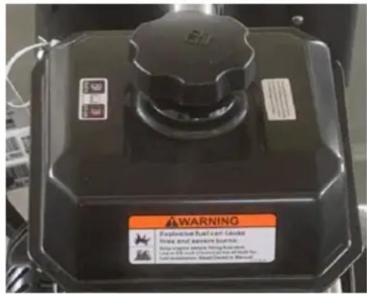
6.2.1 Fuel Filler Cap
Remove this cap to add unleaded gasoline to the fuel tank. Make su fuel filler cap is tightened securely. DO NOT overfill.
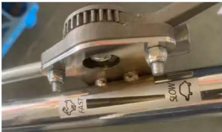
6.2.2 Throttle Lever
The throttle lever is used to adjust engine RPM speed (lever advance forward SLOW, lever back toward operator FAST).
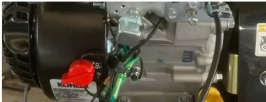
6.2.3 Engine ON/OFF Switch
ON position permits engine starting, OFF position stops engine operati
natural_image
Close-up of a mechanical assembly with visible wiring, springs, and components (no readable text or symbols)6.2.4 Recoil Starter (Pull Rope)
Manual-starting method. Pull the starter grip until resistance is felt, the pull briskly and smoothly.

natural_image
Close-up of a camera module with visible lens, gear, and adjustment knob (no readable text or symbols)6.2.5 Fuel Valve Level
OPEN to let fuel flow, CLOSE to stop the flow of fuel.
6.2.6 Choke Lever
Used in the starting of a cold engine or in cold weather conditions, choke enriches the fuel mixture.
6.2.7 Air Cleaner
The air cleaner prevents dirt and other debris from entering the fuel. To access the filter element, remove the wing-nut on top of the air canister.
NOTE:
Do not operate the engine without an air filter, with a damaged filter, or a filter in need of replacement. This will allow dirt to e engine and cause rapid engine wear.
6.2.8 Spark Plug
The spark plug provides a spark to the ignition system. Clean the sp plug once a week. Set the spark plug gap to 0.6 - 0.7mm (0.028 -
6.2.9 Muffler
The muffler is used to reduce noise and emissions from the engine.

WARNING
Engine components can generate extreme heat. To prevent burns, DO NOT touch these areas while the engine is running or immediately at operating.
NEVER operate the engine with the muffler removed.
6.2.10 Fuel Tank
The fuel tank holds unleaded gasoline. For more information, refer to engine owner's manual.
7. PRE-INSPECTION
NEVER operate the power trowel in a confined area or enclosed str that does not provide ample free flow of air.
ALWAYS wear approved eyewear and hearing protection before operating the trowel.
NEVER place hands or feet inside the guard rings while the engine running.
ALWAYS shut the engine down before performing any kind of maintenance on the trowel.
It is recommended that the trowel's kill switch be used to stop the e after every use. Doing this will verify that the switch is working proper presents no danger to the operator.
7.1 Before Starting
7.1.1 Read the safety instructions at the beginning of this manual.
7.1.2 Clean the power trowel by removing dirt and dust, particularly in engine cooling air inlet, carburetor, and air cleaner.
7.1.3 Check the air filter for dirt and dust. If the air filter is dirty, re with a new one as required.
7.1.4 Check the carburetor for external dirt and dust. Clean it with d compressed air.
7.1.5 Check fastening nuts and bolts for tightness.
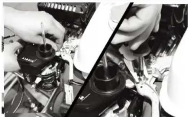
7.2 Engine Oil Check
7.2.1 To check the engine oil level, place the power trowel on a set-level ground with the engine stopped.
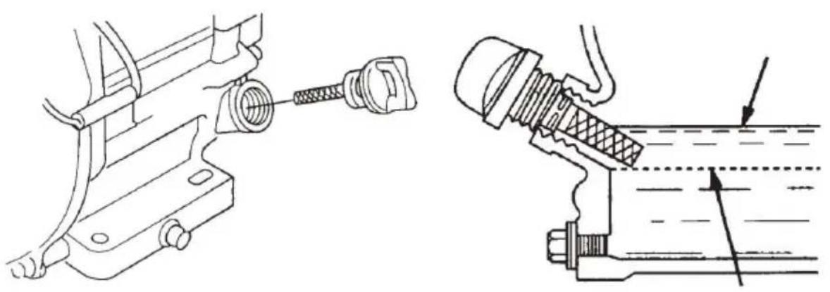
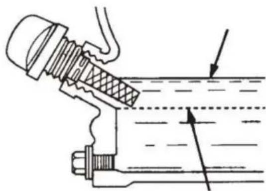
7.2.2 Remove the filler dipstick from the engine oil filler hole (FIG. 2 wipe it clean.
7.2.3 Insert and remove the dipstick without screwing it into the filler Check the oil level shown on the dipstick.
7.2.4 If the oil level is low (FIG. 3), fill to the edge of the oil filler the recommended with SAE10W-30 4 stroke oil. Maximum oil capacity 400 cc.
natural_image
Technical line drawing showing mechanical assembly with threaded fastener and pipe fitting (no text or symbols)FIG.2 FIG.3
7.3 Fuel Check
Engine fuels are highly flammable and can be dangerous if mishandle DO NOT smoke while refueling. DO NOT attempt to refuel the trowel engine is hot or running.
7.3.1 Remove the gasoline cap that is located on top of the fuel tar 7.3.2 Visually inspect to see if fuel level is low. If fuel is low, reple 89 Octane gasoline.
7.3.3 When refueling, be sure to use a strainer for filtration. DO NO ^- the fuel. Wipe up any spilled fuel.
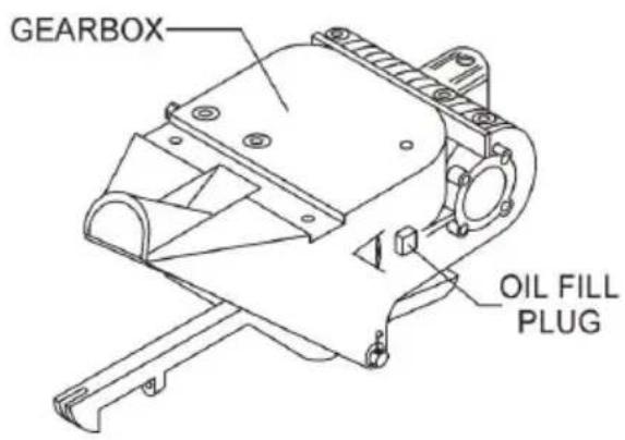
FIG.4
7.4 Gearbox Oil
7.4.1 Determine if the gearbox oil is low by removing the oil plug to the side of the
gearbox. This plug will be marked by the "check" decal. See FIG. 4. correct level of the lubrication oil should be to the bottom of the fill 7.4.2 If lubrication oil begins to seep out as the drain plug is being then it can be assumed that the gearbox has a sufficient amount of 7.4.3 If lubrication oil does not seep out as the drain plug is being fill with type ISO 680 gearbox lubricant oil until the oil filler hole over
7.5 V-Belt Check
A worn or damaged V-belt can adversely affect the performance of y power trowel. If a V-belt is defective or worn out, simply replace the as outlined in the maintenance section of this manual.
7.6 Blade Check
Before starting, check for worn or damaged blades. If one blade is v while the others look new, this could be because of a blade pitch p Refer to the maintenance section of this manual for instructions on th blade pitch adjustment procedure. Replace any worn out blades.
7.7 SAFETY KILL SWITCHES
This power trowel has been equipped with a safety kill switch. Safety switches should be tested every time the engine is started.
NOTE
NEVER! disable or disconnect the kill switch. It is provided for operator safety. Injury may result if it is disabled, disconnected, or improperly maintained.
7.8 HANDLE PRESS KILL SWITCH
Located on the main handle tube is a red switch (FIG. 5). The switch mechanism of this switch should operate freely and should always be in this condition. With the switch in the OFF position, the engine should start or run. The purpose of this switch is to stop the engine in a situation, (i.e.-the operator releasing the handle during operation).
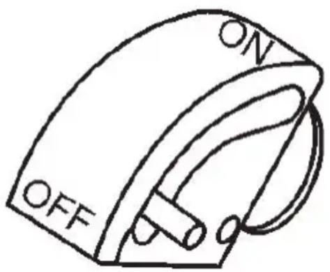
FIG.5
DO NOT let the machine sit unused with the engine at high speed extended period of time. It will cause premature belt wear or may de the belt.
ALWAYS set the engine speed to idle when the hand clutch is dise
8. INITIAL START-UP
Lifting the Trowel Onto a Slab
8.1 Auxiliary Lifting Tube
Remove the auxiliary lifting tube located on top of the main handle. The tube into the socket located on the opposite side of the gearbox the handle. Make sure that the hole in the tube engages with the p socket. With one person lifting from the main handle, and another lifting from the auxiliary lifting tube, pick up the machine to move onto a s

WARNING
The trowel must be stabilized by the person carrying the operato handle. If it is not stabilized properly the handle may swing around and flip the trowel, thus causing damage to the trowel and bodil injury.
8.2 Lifting Bale
The lift bale is optional on new trowels. It provides an optimal lift po moving the trowel. Lift bales or forklift can be used to lift a trowel u building with a crane.
Using a crane to move a machine with a lift bale is highly recommend and is perfectly safe for the machine. Extra care should be taken with lifting the machine off the ground, though. Serious damage to the main or personal injury could be caused by dropping a trowel.
8.2 Lifting Bale Continued
This section is intended to assist the operator with the initial start-up walk-behind trowel. It is extremely important that this section be read carefully before attempting to use the trowel in the field.
DO NOT use your trowel until this section is thoroughly understood.

WARNING
DO NOT attempt to operate the trowel until the Safety, General Information, and Inspection sections of this manual have been read and thoroughly understood. Depending on the engine manufacturer
operating steps may vary. See engine manufacturer's operating manual.
9. STARTING THE ENGINE
9.1 Place the engine fuel valve lever (FIG. 6) to the "ON" position.
9.2 Place the trowel's throttle lever (FIG. 1) to the "IDLE" position.
9.3 Place the choke lever (FIG. 7) in the "CLOSED " position if stable cold engine.
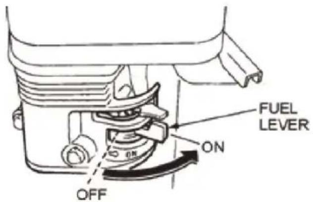
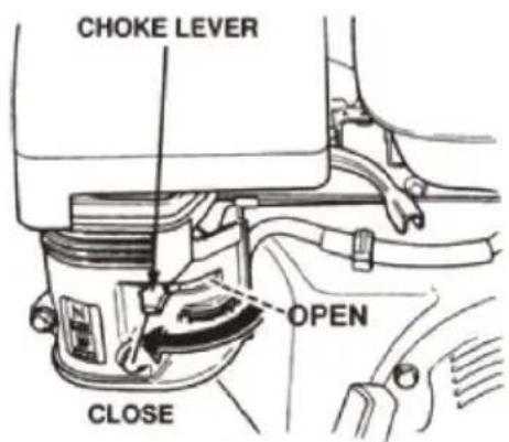
FIG.6 FIG.7
9.4 Place the choke lever (FIG. 8) in the "OPEN" position if starting engine or the temperature is warm.
9.5 Place the engine ON/OFF switch (FIG. 9) in the "ON" position.
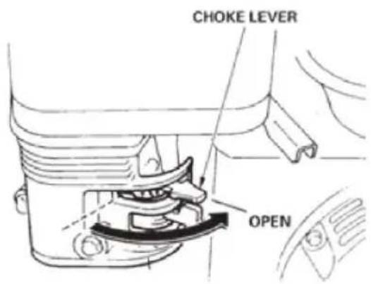
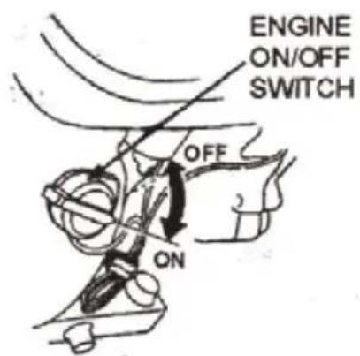
FIG.8 FIG.9
9.6 Grasp the starter grip (FIG. 10) and slowly pull it out. The resis becomes the hardest at a certain position, corresponding to the
compression point. Pull the starter grip briskly and smoothly for starting
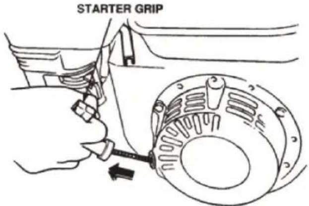
FIG.10
9.7 If the engine has started, slowly return the choke lever (FIG. 7) OPEN position. If the engine has not started repeat steps 1 through 9.8 Before the trowel is placed into operation, run the engine for seven minutes. Check for fuel leaks, and noises that would associate with a V-belt cover or component.
9.9 To begin troweling, move the throttle lever (FIG. 11) toward the position.

FIG.11
10. STOPPING THE ENGINE
10.1 Move the throttle lever to the IDLE or SLOW position (FIG. 11) run the engine for three minutes at low speed.
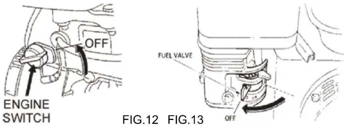
10.2 After the engine cools, turn the engine start/stop switch to the 'position (FIG. 12).
10.3 Close the fuel shut-off valve (FIG. 13) by moving the fuel valve to the OFF position.
11. OPERATION
The following steps are intended as a basic guide to machine operation and are not to be considered a complete guide to concrete finishing. the “Training” section of this manual for more information.
11.1 Maneuvering the Trowel
11.1.1 Get into the operator's position behind the handle. With a secure foothold and a rm grasp on the handles slowly increase the engine speed until the desired blade speed is obtained.
11.1.2 To maneuver the trowel, gently lift up on or press down on trowel handle.
To move the machine to the operator's left, lift up on the handle, to the machine to the right, push down on the handle.
11.1.3 Adjust the blade pitch on the Standard handle, by turn the Pi Adjust Wheel clockwise or counter-clockwise.
• To move the trowel to the operator's left, Lift up on the handle. move the trowel to the right push down on the handle.
- Remember! that if you let goof the trowel, just step away and trowel come to a complete STOP before trying to recover the tro
- The best method for finishing concrete is to slowly walk back with the trowel, guiding the trowel from side to side. This will c footprints on wet concrete.
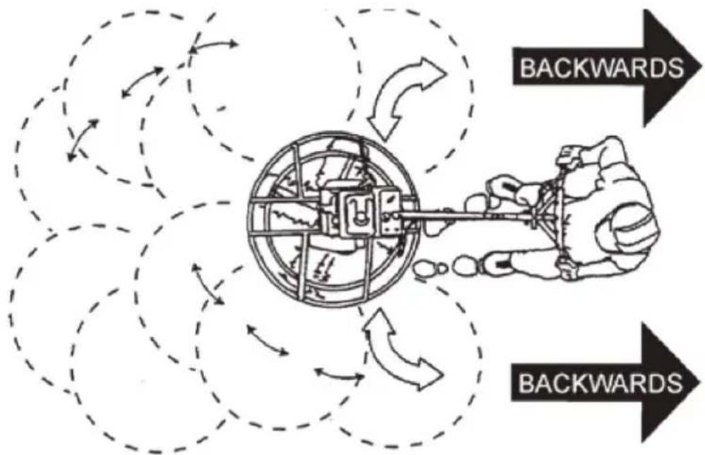
FIG.14

WARNING
NEVER place your feet or hands inside the guard rings while starting operating this equipment.
ALWAYS keep clear of rotating or moving parts while operating this equipment.
12. ACCESSORY OPTIONS
12.1 Blades
NOTE
Blades should be changed when they fail to finish concrete in a sati manner.
Blades are a vital part of finishing concrete. This Trowel has been done to finish concrete and is built to stringent quality standards out of the trowel steel. If you need replacement blades, consult your parts list in manual for part numbers.
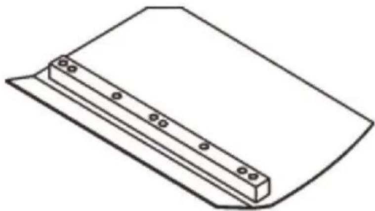
12.2 Combo Blades
This trowel was equipped with combination FLOAT/FINISH (FIG. 15) blades as original equipment. These blades have been designed for optimum performance in both the floating and finishing operations. The
blades are versatile and should take care of most troweling needs.
natural_image
Line drawing of a rectangular object with a recessed top and a horizontal base, featuring small circular indentations on the side (no text or symbols)FIG.15
12.3 Finish Blades (Optional)
These blades have been specifically designed for finish operations with this trowel. They will provide a premium surface finishing capability from your trowel. They should only be used after the concrete has set to point where the trowel does not sink into the concrete when placed
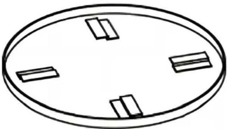
12.4 Clip-On Float Blades (Optional)
These blades will clip (FIG.16) on to an existing installed blade, allow your finisher to float on “wet” concrete so that the troweling operation begins as early as possible. They are easily removable, so that after floating operation, when the concrete is sufficiently cured, they can be removed to expose the finish blades for continued troweling.
natural_image
Simple line drawing of an oval shape with four rectangular cutouts on its sides (no text or symbols)FIG.16
12.5 Float Discs (Optional)
These round discs attach to the spiders and allow the machine to “fl “wet” concrete. The disc design allows early floating and easy movement
from wet to dry areas. They are also very effective in embedding lar aggregates and surface hardeners.
13. MAINTENANCE
13.1 Maintenance Schedule
Daily (8-10 Hours)
- Check the oil level in the engine crankcase and gear box, fill as necessary.
- Check V-belt.
Weekly (50-60 Hours)
- Relube arms, thrust collar and clutch
- Replace blades if necessary.
- Check and clean or replace the engine air filter as necessary.
- Replace engine oil and filter as necessary, see engine manual.
Monthly (200-300 Hours)
- Remove, clean, reinstall and relube the arms and thrust collar. Adj blade arms.
Yearly (2000-2500 Hours)
- Check and replace if necessary the arm bushings, thrust collar bus and shaft seals.
- Check pitch control cables for wear.
- Adjust blade speed.
13.2 Trowel Arm Adjustment
Use the following procedure to check and adjust trowel arms, and ch worn or damaged components when it becomes apparent that the trow finishing poorly or in need of routine maintenance. Look for the follow indications. Trowel arm alignment,
worn spider bushings or bent trowel arms may the cause.
- Are blades wearing unevenly? Is one blade completely worn out with others look new?
- Does the machine have a perceptible rolling or bouncing motion wh
use?
- Look at the machine while it is running; do the guard rings “rock down” relative to the ground?
13.2.1 Place the trowel in a FLAT, LEVEL area.
A level, clean area to test the trowel prior to and after is essential. unlevel spots in the floor or debris under the trowel blades will give incorrect perception of adjustment. Ideally, a 5 x 5 Ft. (1.5 x 1.5 Me three-quarter inch (19 mm) thick FLAT steel plate should be used for testing.
13.2.2 Pitch the blades as flat as possible. The adjustment bolts should barely make contact with the lower wear plate on the spiderbox. If o not making contact, adjustment will be necessary. (FIG.17,FIG.4).
13.2 Trowel Arm Adjustment Continued
FIG.17 illustrates, "incorrect alignment", worn spider bushings or bent trowel arms. Check that the adjustment bolt is barely touching (0.10" clearance) lower wear plate. All alignment bolts should be spaced the same distance from the lower wear plate.
1 Adjustment Bolt
2 Lower Wear Plate
3 Surface
4 "Dished" Effect on Finished Concrete
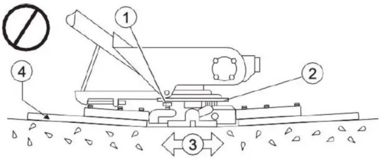
FIG.17
13.3 Trowel Blade Removal
13.3.1 Remove the trowel blades from the trowel arm by removing the hex head bolts from the trowel arm. Set blades aside.
13.3.2 Wire brush any build-up of concrete from all six sides of the arm. Repeat this for the remaining three arms.
13.4 Re-Assembly
13.4.1 Clean and examine the upper/lower wear plates and thrust the collar.
13.4.2 Examine the entire spider assembly. Wire brush any concrete (rust build-up. If any spider components are found to be damaged or misshaped, replace it.
13.4.3 Reinstall bronze bushing on the trowel arms.
13.4.4 Repeat above steps for each trowel arm.
13.4.5 Make sure that the spring tensioner is in the correct position tension on the trowel arm.
13.4.6 With the bronze bushing already installed, insert all the trowel with levers into the spider plate.
13.4.7 Use care to align the grease hole on the bronze bushing with grease hole fitting on the spider plate.
13.4.8 Lock the trowel arms in place by tightening the hex head bolt zerk grease fitting and jam nut.
13.4.9 Re-install the blades onto the trowel arms.
13.4.10 Install the stabilizer ring onto the spider assembly.

WARNING
Disconnect the spark plug wire from the spark plug and secure away the engine before performing maintenance or adjustments on the mach
①Blade
②Blade Arm
③Hex Head Bolt
④Lock Washer
⑤Remove from Arm
13.5 Changing
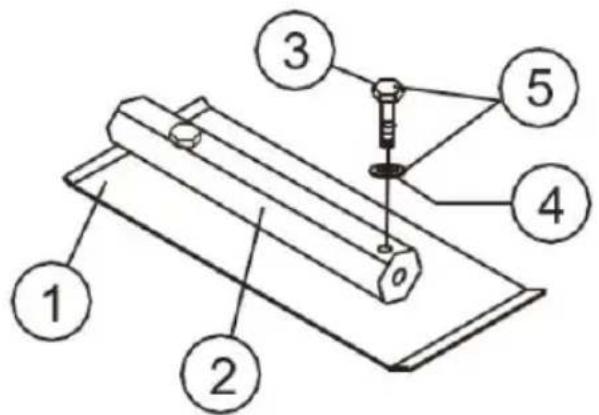
FIG.18
Only
We recommend that all of the blades are changed at the same time trowel may wobble or bounce if not.
13.5.1 Place the machine on a flat, level surface. Adjust the blade p control to make the blades as flat as possible.
NOTE
Pay attention to the blade orientation on the trowel arm.
13.5.2 Remove the two bolts and lock the washers that secure the trowel arm.
13.5.3 Remove the blade.
13.5.4 Using a wire brush, scrape all concrete particles and forgein d from the trowel arm.
13.5.5 Install the new trowel blade onto the trowel arm. Make sure the blade is installed correctly, maintaining the proper orientation for direct of rotation.
13.5.6 Reinstall the two bolts and lock washers that secure the blade trowel arm. Tighten the bolts securely.
13.5.7 Repeat steps for all remaining blades.
13.6 Installing Pans onto Finisher Blades

WARNING
Lifting/CRush Hazard.
Do NOT lift the trowel with the pans attached.
ALWAYS install the pans on the work area or an area that is not to/level with the work area.
DO NOT lift the trowel when the pans are attached.
13.6.1 Lift the trowel just enough to slide the pan under the blades. the blades adjacent to the Z-clips, lower the finisher onto the pan.
13.6.2 Rotate the blades into position under the Z-clips. Ensure that the blades are rotated in the direction of travel when the machine is in operation. Or, use the engine to rotate the blades into position.
13.6.3 Attach the blade tie-downs to the far side of the Z-clip bracket tie-down knobs.
13.6.4 Before the machine is put back into operation, check to make that the blade edges are secured under the Z-clips.
13.6.5 Before the machine is put back into operation, check to make that the tie-downs are secured firmly over the edges of the blade.
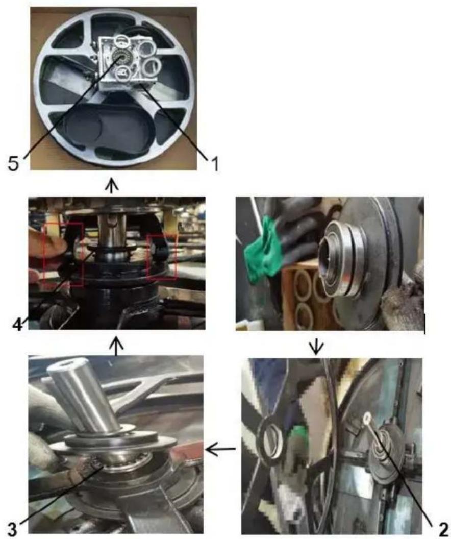
13.7 Spider Box Removal
13.7.1 Once it is determined that an adjustment is required, remove 1 spider assembly from the gearbox shaft as follows:
13.7.2 Remove the zerk fitting and allen head screw designated by the letter "S".
13.7.3 On the opposite side of the spider block, there is another zer and allen head screw. Remove both of these components.
13.7.4 Lift the upper trowel assembly off of the spider assembly.
NOTE
A slight tap with a rubber mallet may be necessary to dislodge the from the main shaft of the gearbox.
14 Parts List
Handle
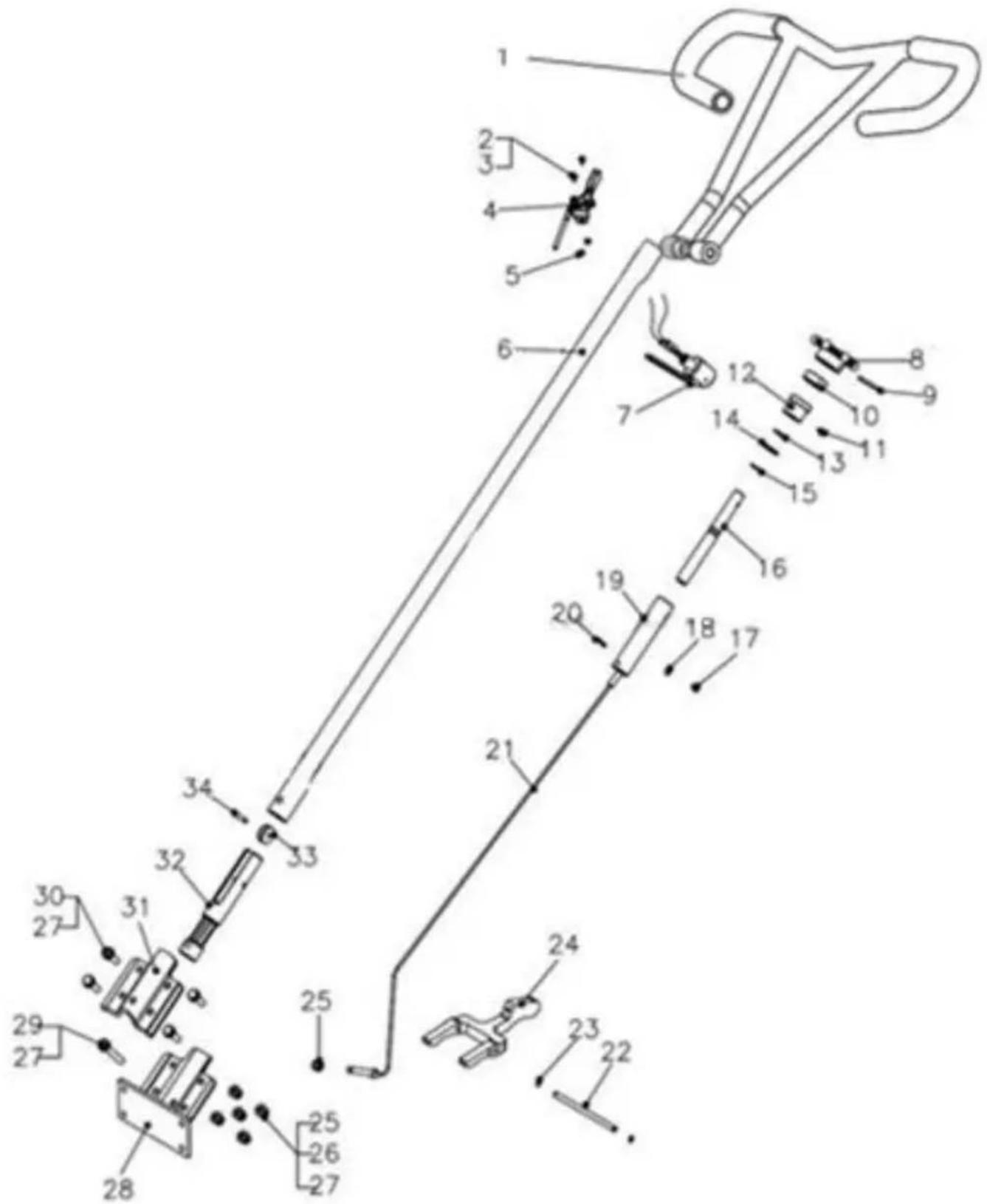
| REF | Parts No. | Description | Q'TY | Dimension |
| 1 | RG-003 | Plastic Cover | 2 | |
| 2 | QSC-M4*8 | Screw | 2 | M4x8 |
| 3 | QWS-PM4 | Plate Washer | 2 | M4 |
| 4 | TSA-01 | Throttle Assy. | 1 | |
| 5 | QNT-NM4 | Nylock Nut | 2 | M4 |
| 6 | W436F-001 | Handle WA | 1 | |
| 7 | PAS-02 | Stop Switch(release bar Type) | 1 | |
| 8 | 436F-01-001 | Adjust Knob | 1 | |
| 9 | QSP-5X50 | Spring Pin | 1 | 5x50 |
| 10 | QBR-51104 | Bearing | 1 | |
| 11 | QBL-M6X10 | Bolt | 1 | M6x10 |
| 12 | 436F-01-004 | Aluminium Guide | 1 | |
| 13 | QWS-WM19 | Wave Washer | 1 | M19 |
| 14 | QWS-PM19 | Plate Washer | 1 | M19 |
| 15 | QSR-S18 | Snap Ring | 1 | S18 |
| 16 | 436F-01-002 | Adjust Screw Pipe | 1 | |
| 17 | QBL-M6X8 | Bolt | 1 | M6X8 |
| 18 | QWS-PM6 | Spring Washer | 1 | M6 |
| 19 | 436F-01-003 | Screw Guide | 1 | |
| 20 | QSP-5X30 | Spring Pin | 1 | 5X30 |
| 21 | 436F-01-007 WT | Steel Wire | 1 | |
| 22 | 436F-02-004 | Yoke Arm Pin | 1 | |
| 23 | QSR-S10 | Snap Ring | 2 | S10 |
| 24 | 436F-02-003 B | Yoke Arm | 1 | |
| 25 | QNT-NM10 | Nylock Nut | 10 | M10 |
| 26 | QWS-SM10 | Spring Washer | 14 | M10 |
| 27 | QWS-PM10 | Plate Washer | 18 | M10 |
| 28 | 436F-02-001 | Handle Support Base | 1 | |
| 29 | QBL-M10X70 | Bolt | 1 | M10X70 |
| 30 | QBL-M10X35 | Bolt | 4 | M10X35 |
| 31 | 436F-02-002 | Upper Bracket | 1 | |
| 32 | 436F-01-005 | Aluminum yoke | 1 | |
| 33 | 436A-01-010 | Wheel | 1 | |
| 34 | QSP-3X30 | Spring Pin | 1 | 3X30 |
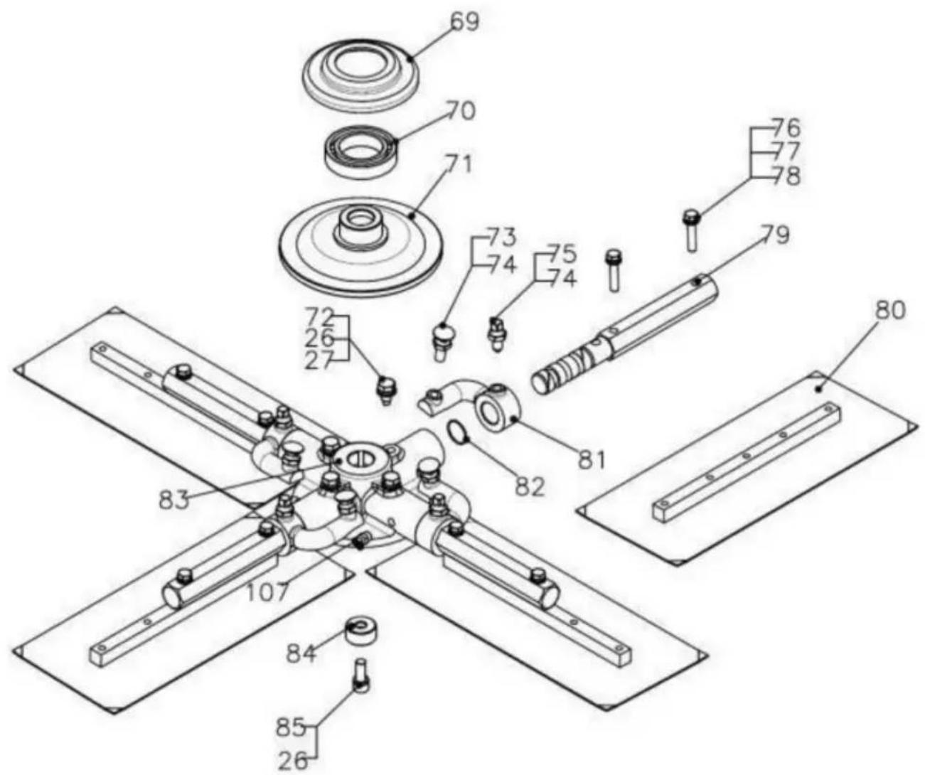
Blade
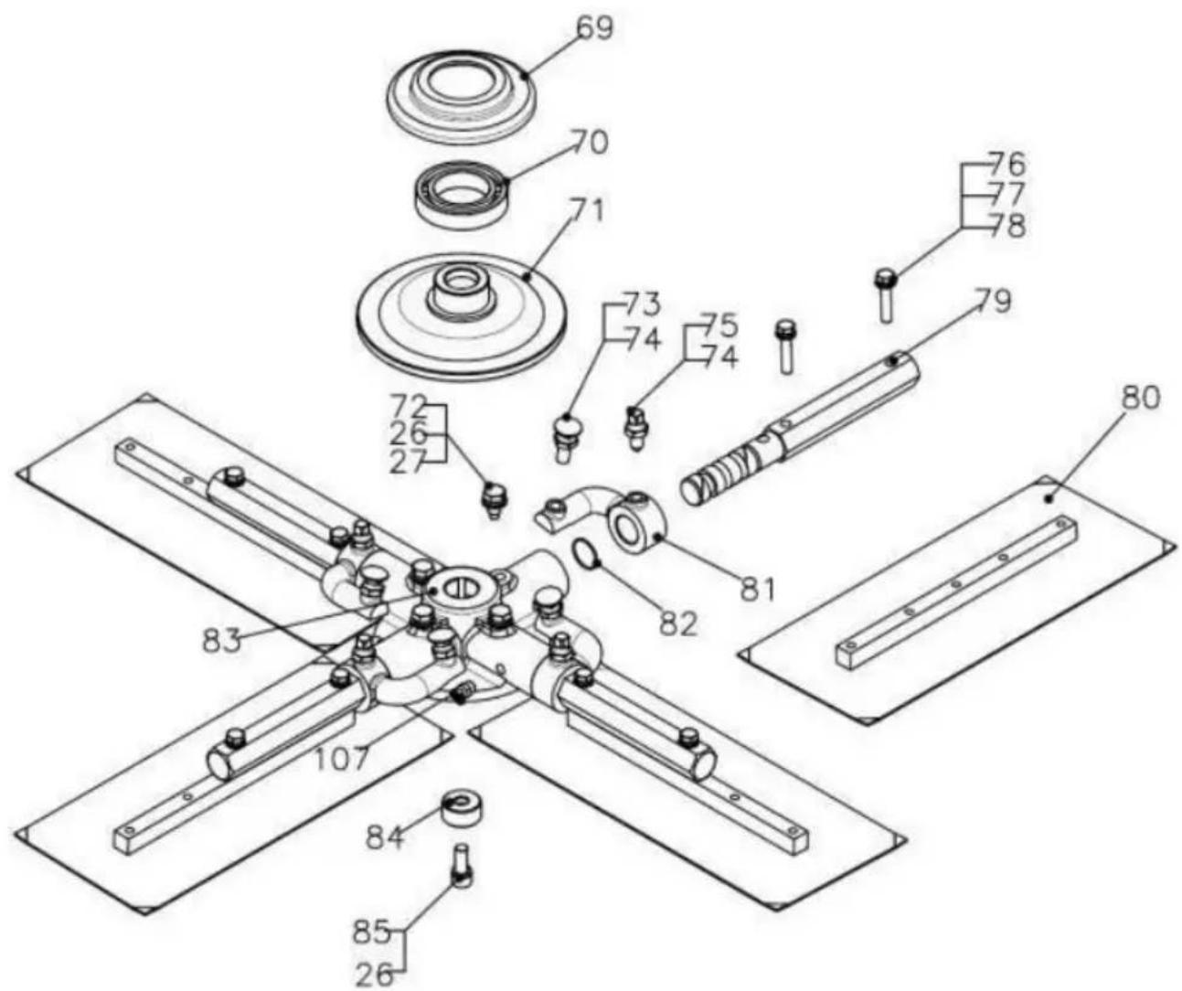
| REF | Parts No. | Description | Q'TY | Dimension |
| 26 | QWS-SM10 | Spring Washer | 5 | M10 |
| 27 | QWS-PM10 | Plate Washer | 4 | M10 |
| 69 | 436F-02-005B | Press Plate Cap | 1 | |
| 70 | QBR-6009 | Bearing | 1 | 6009 |
| 71 | 436F-02-006B | Press Plate Cap | 1 | |
| 72 | QBL-M10X20 | Bolt | 4 | M10X20 |
| 73 | QBL-BBM10X35 | Round Head Bolt | 4 | M10X35 |
| 74 | QNT-TM10 | Thin Nut | 8 | M10 |
| 75 | QBL-SHM10X30 | Square Head Bolt | 4 | |
| 76 | QBL-7/16X11/2 | Bolt | 8 | 7/16*3/2L |
| 77 | QWS-SM8 | Spring Washer | 8 | M8 |
| 78 | QWS-PM8 | Plate Washer | 8 | M8 |
| 79 | 436F-02-009B | Blade Arm | 4 | |
| 80 | 436F-02-014 | Blade Assembly | 4 | |
| 81 | 436F-02-008 | Tilt Arm | 4 | |
| 82 | QOR-S22 | O-ring | 4 | 22x1.5t |
| 83 | 436F-02-007B | Spider | 1 | |
| 84 | 436F-02-010 | Spider Bushing | 1 | |
| 85 | QBL-LM10X30 | Socket Bolt | 1 | M10x30 |
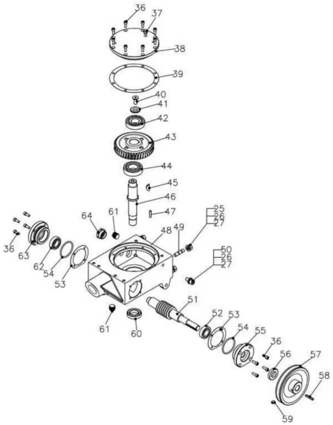
Gear Box

| REF | Parts No. | Description | Q'TY | Dimension |
| 436F-03 | Gear Box Assembly | 1 | ||
| 25 | QNT-NM10 | Nylock Nut | 4 | M10 |
| 26 | QWS-SM10 | Spring Washer | 5 | M10 |
| 27 | QWS-PM10 | Plate Washer | 5 | M10 |
| 36 | QBL-M6X16 | Bolt | 16 | M6X16L |
| 37 | QRV-M8 | Release Valve | 1 | |
| 38 | 436F-03-004 | Big Cover | 1 | |
| 39 | 436F-03-005 | Gasket of Big Cove | 1 | |
| 40 | QBL-FHM10x25 | Flat Socket Head Bo | 1 | M10x25 |
| 41 | QWS-SSM10 | Washer | 1 | M10 |
| 42 | QBR-30305 | Bearing | 1 | 30305 |
| 43 | 436F-03-008 | Worm Gear | 1 | |
| 44 | QBR-6206 | Bearing | 1 | 6206 |
| 45 | QKY-W6X10X25 | Wood Key | 1 | 6X10X25 |
| 46 | 436F-02-012 | Main Shaft | 1 | |
| 47 | QKY-6X25 | Key | 1 | 6X25 |
| 48 | 436F-03-001 | Shell | 1 | |
| 49 | QBL-STM10x40 | Stud Bolt | 4 | M10x40 |
| 50 | QBL-M10X16 | Bolt | 1 | M10X16 |
| 51 | 436F-03-007 | Worm Shaft | 1 | |
| 52 | QBR-32004 | Bearing | 1 | 32004 |
| 53 | 436F-03-006 | Gasket of Side Cove | 2 | |
| 54 | QOR-P55 | O-Ring | 2 | 55x3.5t |
| 55 | 436F-03-003 | Output Side Cover | 1 | |
| 56 | QOS-20X40X8 | Oil Seal | 1 | |
| 57 | 436F-04-005 | Pulley | 1 | |
| 58 | QKY-5X35 | Key | 1 | 5X35 |
| 59 | QBL-M8X10 | Bolt | 1 | M8X10 |
| 60 | QOS-27X47X10 | Oil Seal | 1 | 27X47X10 |
| 61 | 436A-03-008WT | Oil Drain | 2 | |
| 62 | QBR-6004 | Bearing | 1 | 6004 |
| 63 | 436F-03-002 | Side Cover | 1 | |
| 64 | QOCW-M27x1.5 | Oil Check Windows | 1 | M27x1.5 |
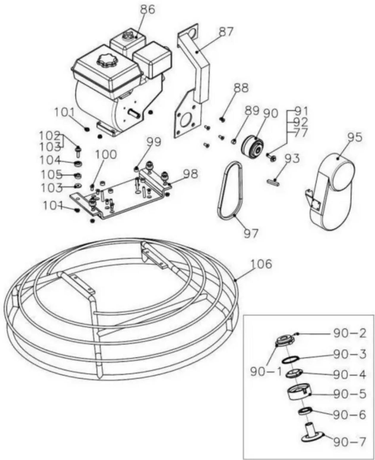
Safety Ring
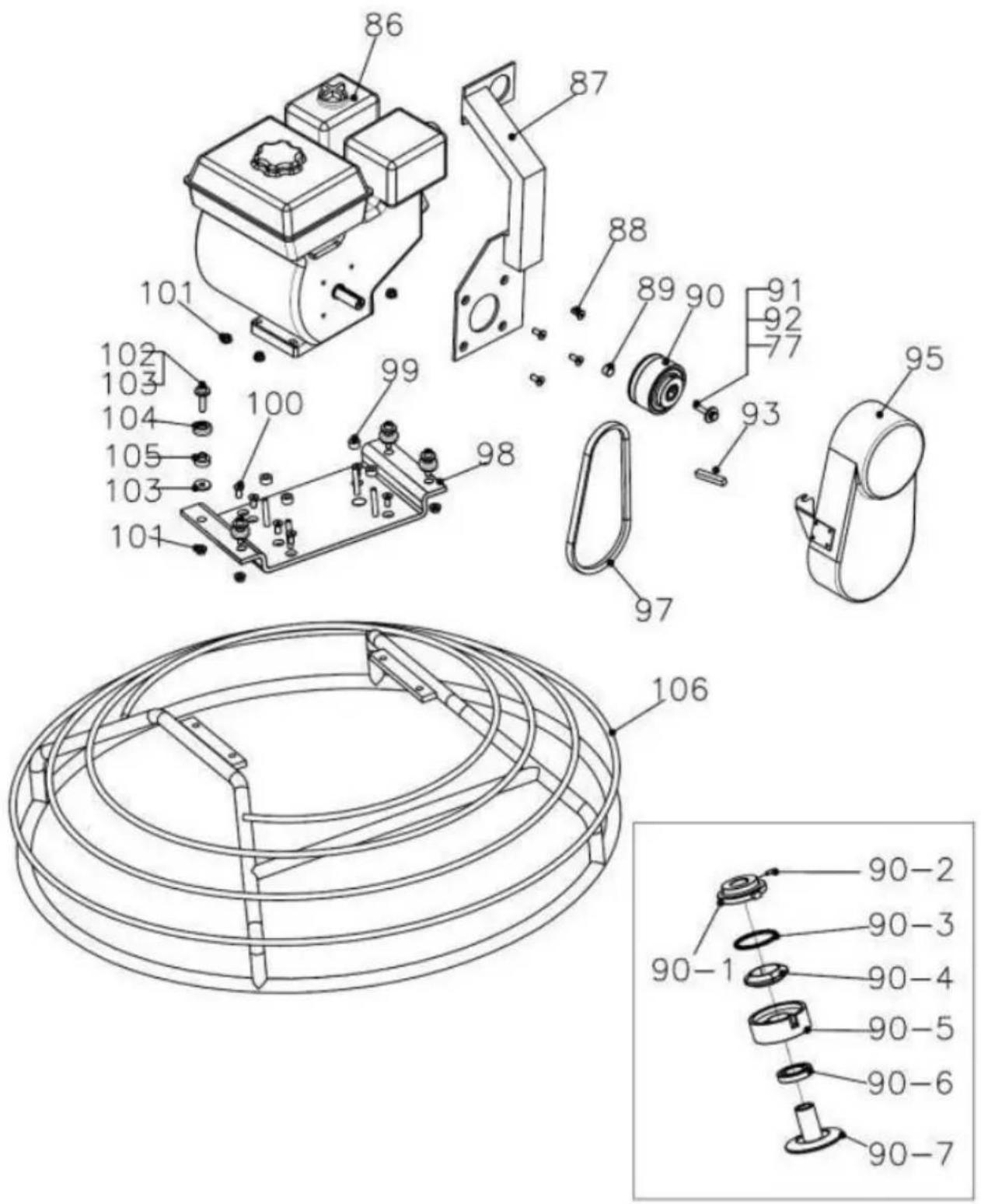
| REF | Parts No. | Description | Q'TY | Dimension |
| 77 | QWS-SM8 | Spring Washer | M8 | |
| 86 | GX160 | Engine GX-160 | 1 | |
| 87 | W436F-005 | Hook Lift | 1 | |
| 88 | QBL-SHM8X20 | Socket Head Cap Bo | 4 | |
| 89 | 436F-04-013 | Clutch Busing | 1 | |
| 90 | CA-01 | Clutch | 1 | |
| 90-1 | CA-01-004 | Face Plate | 1 | |
| 90-2 | QBL-AM8x16 | Set Screw | 2 | M8x16 |
| 90-3 | CA-01-005 | Clutch Spring | 1 | |
| 90-4 | CA-01-003 | Shoe Weight | 1 | |
| 90-5 | CA-01-002 | Clutch Drum | 1 | |
| 90-6 | QBR-6006 | Bearing | 1 | 6006 |
| 90-7 | CA-01-001 | Clutch Shaft | 1 | |
| 91 | QBL-M8X35 | Bolt | 1 | M8X35 |
| 92 | QWS-SPM8 | Special Plate Washer | 1 | M8 |
| 93 | QKY-5x5x50 | Key | 1 | 5x5x50 |
| 95 | 436F-04-006 | Belt Cover | 1 | |
| 97 | QBT-A26 | V-Belt | 1 | A26 |
| 98 | W436F-002 | Engine Mount Plate | 1 | |
| 99 | 436F-04-107 | Engine Mount Bushing | 4 | |
| 100 | QBL-FHM8X20 | Flat Head Cap Bolt | 4 | M8X20 |
| 101 | QNT-M8 | Nut | 8 | M8 |
| 102 | QBL-LM8X40 | Socket Head Bolt | 4 | M8X40 |
| 103 | QWS-PM8 | 8 | M8 | |
| 104 | 436F-04-004 | Cup | 4 | |
| 105 | 436F-04-003 | Rubber | 4 | |
| 106 | W436F-004B | Safety Ring | 1 |
VEVOR®
TOUGH TOOLS, HALF PRICE
Technical Support and E-Warranty Certificate
www.vevor.com/support
VEVOR®
TOUGH TOOLS, HALF PRICE
natural_image
Line drawing of a cleaning lathe machine with a mesh base (no text or symbols)BESOIN D'AIDE? CONTACTEZ-NOUS!
www.vevor.com/support
natural_image
Close-up of a metallic mechanical component with a grid-patterned handle and a highlighted section (no visible text or symbols)natural_image
Close-up of a metallic mechanical component with a red box highlighting a detail (no visible text or symbols)5.4□□Levier□□de□commande□□de□
natural_image
Close-up of a metal hanger with a small inset image showing a mechanical component (no text or symbols visible)□□□dix□□□
5.5 Guidons de vélo
natural_image
Close-up of a mechanical assembly with visible wiring, components, and a red safety knob (no readable text or symbols)natural_image
Close-up of a motorcycle's front wheel and gear assembly with a highlighted component (no visible text or symbols)natural_image
Technical line drawing of a mechanical assembly with a spring-loaded connector (no text or symbols)FIG.2

natural_image
Technical line drawing of a mechanical assembly with no visible text or symbolsFIG.3
12. OPTIONS D'ACCESSOIRES
12.1 Lames
NOTE
natural_image
Line drawing of a rectangular object with a recessed top and side grooves, no text or symbols present.FIG.15
12.3 Lames de finition (en option)
natural_image
Simple hand-drawn oval shape with four rectangular cutouts on its sides (no text or symbols)FIG.16
FBIIGa.d1e8s
Seulement
Machine Translated by Google
| 29QBL-M10X70 | Boulon | 1 | M10X70 | |
| 30QBL-M10X35 | Boulon | 4 | M10X35 | |
| 31 | 436F-02-002 | Support supérieur | 1 | |
| 32 436F-01-005 | Joug en aluminium | 1 | ||
| 33 436A-01-010 | Roue | 1 | ||
| 34 | QSP-3X30 | Goupille élastique | 1 | 3X30 |
Lame

natural_image
Line drawing of a cleaning lathe machine with a mesh base (no text or symbols)BRAUCHEN SIE HILFE? KONTAKTIERE UNS!
natural_image
Close-up of a mechanical assembly with metal rods and wiring (no visible text or symbols)natural_image
Close-up of a person operating a mechanical assembly with metal rods and wiring (no visible text or symbols)natural_image
Close-up of hands assembling or adjusting a mechanical component (no visible text or symbols)natural_image
Close-up of a hand using a tool to adjust or repair a mechanical component (no visible text or symbols)natural_image
Close-up of a person using a mechanical tool, no visible text or symbolsnatural_image
Close-up of a hand adjusting a bicycle wheel handle using a wrench (no visible text or symbols)natural_image
Close-up of hands operating a mechanical device with a knob and a cylindrical component (no visible text or symbols)natural_image
Close-up of hands installing or adjusting electronic components on a mechanical assembly (no visible text or symbols)natural_image
Close-up of hands installing or adjusting electronic components on a mechanical device (no visible text or symbols)natural_image
Close-up of a mechanical assembly with a green arrow pointing to a component, no visible text or symbolsnatural_image
Close-up of a mechanical device with a circular indicator labeled 'LOWER' and 'FAISE', no readable text or symbols beyond the label.natural_image
Close-up of a metallic mechanical component with a highlighted section (no visible text or symbols)natural_image
Close-up of a metallic mechanical component with a red zoomed-in inset highlighting a detail (no text or symbols visible)natural_image
Close-up of a metal hanger with a small inset image showing a mechanical component (no text or symbols visible)5.5 Fahrradlenker
6.2.2 Gashebel
natural_image
Close-up of a mechanical assembly with visible wiring, components, and a red indicator label (no readable text or symbols)natural_image
Close-up of a black quad-cleaner motorcycle with visible branding and a green button (no readable text or symbols)natural_image
Technical line drawing of a mechanical assembly with a spring-loaded connector (no text or symbols)ABB.2

natural_image
Technical line drawing of a mechanical assembly with no visible text or symbolsABB. 3
natural_image
Line drawing of a rectangular object with a recessed top and a horizontal side, featuring evenly spaced circular indentations (no text or symbols)ABB.15
12.3 Finish-Klingen (optional)
natural_image
Simple line drawing of an oval shape with four rectangular cutouts on its sides (no text or symbols)ABB.16
FBIIGa.d1e8s
Nur
| REF | Teile No | Beschreibung | Menge | Dimension |
| 77 | QWS-SM8 | Federscheibe | M8 | |
| 86 | GX160 | Motor GX-160 | 1 | |
| 87 | W436F-005 | Hakenlift | 1 | |
| 88 QBL-SHM8X20 Innensechskantschraube | 4 | |||
| 89 | 436F-04-013 | Kupplungsbusing | 1 | |
| 90 | CA-01 | Kupplung | 1 | |
| 90-1 | CA-01-004 | Frontplatte | 1 | |
| 90-2 QBL-AM8x16 | Stellschraube | 2 | M8x16 | |
| 90-3 | CA-01-005 | Kupplungsfeder | 1 | |
| 90-4 | CA-01-003 | Schuhgewicht | 1 | |
| 90-5 | CA-01-002 | Kupplungstrommel | 1 | |
| 90-6 | QBR-6006 | Lager | 1 | 6006 |
| 90-7 | CA-01-001 | Kupplungswelle | 1 | |
| 91 | QBL-M8X35 | Bolzen | 1 | M8X35 |
| 92 | QWS-SPM8 Spezial-Plattenwascher | 1 | M8 | |
| 93 | QKY-5x5x50 | Schlüssel | 1 | 5x5x50 |
| 95 | 436F-04-006 | Riemenabdeckung | 1 | |
| 97 | QBT-A26 | Keilriemen | 1 | A26 |
| 98 | W436F-002 | Motormontageplatte | 1 | |
| 99 | 436F-04-107 | Motorlagerbuchse | 4 | |
| 100 QBL-FHM8X20 Flachkopfschraube 101 | 4 | M8X20 | ||
| QNT-M8 | Nuss | 8 | M8 | |
| 102 QBL-LM8X40 | Innensechskantschraube | 4 | M8X40 | |
| 103 | QWS-PM8 | 8 | M8 | |
| 104 | 436F-04-004 | Tasse | 4 | |
| 105 | 436F-04-003 | Gummi | 4 | |
| 106 W436F-004B | Sicherheitsring | 1 | ||
VEVOR®
TOUGH TOOLS, HALF PRICE
www.vevor.com/support
VEVOR®
TOUGH TOOLS, HALF PRICE
natural_image
Line drawing of a cleaning lathe machine with a mesh base (no text or symbols)HO BISOGNO DI AIUTO? CONTATTACI!
natural_image
Close-up of hands operating a mechanical device with a knob and a cylindrical component, no visible text or symbolsnatural_image
Close-up of hands assembling electronic components on a mechanical assembly (no visible text or symbols)natural_image
Close-up of hands installing or adjusting a mechanical component with visible wiring and components (no text or symbols)natural_image
Close-up of a mechanical assembly with a green arrow pointing to a component, no visible text or symbolsnatural_image
Close-up of a mechanical device with a circular indicator labeled 'LOWER' and 'FAISE', no readable text or symbols beyond the label.natural_image
Close-up of a metallic mechanical component with a grid-patterned handle and a highlighted section (no visible text or symbols)natural_image
Close-up of a metallic mechanical component with a red box highlighting a detail (no visible text or symbols)natural_image
Close-up of a metal hanger with a small inset image highlighting a mechanical component (no text or symbols visible)natural_image
Close-up of an industrial electric motor with visible wiring and components (no readable text or symbols)natural_image
Close-up of a black quad-clean motorcycle head with visible branding and a green button (no readable text or symbols)6.2.5 Livello valvola carburante
natural_image
Technical line drawing of a mechanical assembly with a spring-loaded connector (no text or symbols)FIG.2

natural_image
Technical line drawing of a mechanical assembly with no visible text or symbolsFIG.3
7.3 Controllo del carburante
natural_image
Line drawing of a rectangular object with a recessed top and a horizontal side, featuring evenly spaced circular indentations (no text or symbols)FIGURA 15
natural_image
Simple hand-drawn oval shape with four rectangular cutouts on its surface (no text or symbols)FIGURA 16
FBIIGa.d1e8s
Soltanto
Machine Translated by Google
| 29 QBL-M10X70 | Bullone | 1 | M10X70 | |
| 30QBL-M10X35 | Bullone | 4 | M10X35 | |
| 31 | 436F-02-002 | Staffa superiore | 1 | |
| 32 436F-01-005 | Giogo in alluminio | 1 | ||
| 33 436A-01-010 | Ruota | 1 | ||
| 34 | QSP-3X30 | Perno a molla | 1 | 3X30 |
Lama

| RIF | Parti n. | Descrizione | Dimensione Qtà | |
| 26 | QWS-SM10 | Rondella elastica | 5 | M10 |
| 27 | QWS-PM10 | Lavapiatti | 4 | M10 |
| 69 | 436F-02-005B | Premere il cappuccio della piastra | 1 | |
| 70 | QBR-6009 | Cuscinetto | 1 | 6009 |
| 71 | 436F-02-006B | Premere il cappuccio della piastra | 1 | |
| 72 | QBL-M10X20 | Bullone | 4 | M10X20 |
| 73 | QBL-BBM10X35 Bullone a testa tonda | 4 | M10X35 | |
| 74 | QNT-TM10 | Noce sottile | 8 | M10 |
| 75 | Bullone a testa quadrata | QBL-SHM10X30 76 | 4 | |
| QBL-7/16X11/2 | 8Bullone | 7/16*3/2L | ||
| 77 | QWS-SM8 | Rondella elastica | 8 | M8 |
| 78 | QWS-PM8 | Lavapiatti | 8 | M8 |
| 79 | 436F-02-009B | Braccio a lama | 4 | |
| 80 | 436F-02-014 | Assemblaggio della lama | 4 | |
| 81 | 436F-02-008 | Braccio inclinabile | 4 | |
| 82 | SCRIVI-S22 | O-ring | 4 | 22x1,5t |
| 83 | 436F-02-007B | Ragno | 1 | |
| 84 | 436F-02-010 | Boccola a ragno | 1 | |
| 85 | QBL-LM10X30 | Bullone a presa | 1 | M10x30 |
Riduttore

elettronica www.vevor.com/support
VEVOR®
TOUGH TOOLS, HALF PRICE
natural_image
Line drawing of a cleaning lathe machine with a mesh base (no text or symbols)natural_image
Close-up of a mechanical assembly with metal rods and wiring (no visible text or symbols)natural_image
Close-up of a person operating a mechanical assembly with metal rods and wiring (no visible text or symbols)natural_image
Close-up of hands assembling or adjusting a mechanical component (no visible text or symbols)natural_image
Close-up of a hand using a tool to adjust or repair a mechanical component (no visible text or symbols)natural_image
Close-up of a person using a mechanical tool, no visible text or symbolsnatural_image
Close-up of a hand using a mechanical tool to adjust a metallic rod (no visible text or symbols)natural_image
Close-up of hands operating a mechanical device with a knob and a cylindrical component (no visible text or symbols)natural_image
Close-up of hands installing or adjusting electronic components on a mechanical assembly (no visible text or symbols)natural_image
Close-up of hands installing or adjusting electronic components on a mechanical assembly (no visible text or symbols)natural_image
Close-up of a mechanical assembly with a green arrow pointing to a component, no visible text or symbols.natural_image
Close-up of a mechanical device with a circular indicator labeled 'LOWER' and 'FAISE', showing internal components and wiring (no readable text beyond labels)natural_image
Close-up of a metallic mechanical component with a highlighted section (no visible text or symbols)5.3 Interruptor de apagado centrífugo
natural_image
Close-up of a metallic mechanical component with a red zoomed-in inset highlighting a small feature (no text or symbols visible)5.4 Palanca de control del acelerador
natural_image
Close-up of a metal hanger with a small inset image highlighting a mechanical component (no text or symbols visible)5.5 Manillar de bicicleta
6.2.2 Palanca del acelerador
natural_image
Close-up of an industrial machine component with visible wiring and a red safety knob (no text or symbols)natural_image
Close-up of a black quadrupole pump with attached sensor and control panel (no visible text or symbols)natural_image
Technical line drawing of a mechanical assembly with a spring-loaded connector (no text or symbols)FIGURA 2

natural_image
Technical line drawing of a mechanical assembly with no visible text or symbolsFIG. 3
natural_image
Line drawing of a rectangular object with a recessed top and side grooves, no text or symbols present.FIG.15
natural_image
Simple line drawing of an oval shape with four rectangular cutouts on its surface (no text or symbols)FIG.16
FIG.17
FBIIGa.d1e8s
Solo
Machine Translated by Google
| 29QBL-M10X70 | Tornillo | 1 | M10X70 | |
| 30QBL-M10X35 | Tornillo | 4 | M10X35 | |
| 31 | 436F-02-002 | Soporte superior | 1 | |
| 32 436F-01-005 | Yugo de aluminio | 1 | ||
| 33 436A-01-010 | Rueda | 1 | ||
| 34 | QSP-3X30 | El pasador de resorte | 1 | 3X30 |
Cuchilla
| ÁRBITRO | Número de piezas | Descripción | Cantidad | Dimensión |
| 26 | QWS-SM10 | Arandela de resorte | 5 | M10 |
| 27 | QWS-PM10 | Lavadora de placas | 4 | M10 |
| 69 | 436F-02-005B | Tapa de la placa de prensa | 1 | |
| 70 | QBR-6009 | Cojinete | 1 | 6009 |
| 71 | 436F-02-006B | Tapa de la placa de prensa | 1 | |
| 72 | QBL-M10X20 | Tornillo | 4 | M10X20 |
| 73 QBL-BBM10X35 Perno de | cabeza redonda | 4 | M10X35 | |
| 74 | QNT-TM10 | Tuerca fina | 8 | M10 |
| 75 QBL-SHM10X30 Perno de | cabeza cuadrada 76 | 4 | ||
| QBL-7/16X11/2 | Tornillo | 8 | 7/16*3/2L | |
| 77 | QWS-SM8 | Arandela de resorte | 8 | M8 |
| 78 | QWS-PM8 | Lavadora de placas | 8 | M8 |
| 79 | 436F-02-009B | Brazo de hoja | 4 | |
| 80 | 436F-02-014 | Conjunto de cuchillas | 4 | |
| 81 | 436F-02-008 | Brazo inclinable | 4 | |
| 82 | ESCRIBIR-S22 | junta tórica | 4 | 22x1,5t |
| 83 | 436F-02-007B | Araña | 1 | |
| 84 | 436F-02-010 | Buje de araña | 1 | |
| 85 | QBL-LM10X30 | Perno | 1 | M10x30 |
Caja de cambios

| ÁRBITRO | Número de piezas | Descripción | Cantidad | Dimensión |
| 436F-03 | Conjunto de caja de cambios | 1 | ||
| 25 | QNT-NM10 | Tuerca de nailon | 4 | M10 |
| 26 | QWS-SM10 | Arandela de resorte | 5 | M10 |
| 27 | QWS-PM10 | Lavadora de placas | 5 | M10 |
| 36 | QBL-M6X16 | Tornillo | deciséis | M6X16L |
| 37 | QRV-M8 | Válvula de escape | 1 | |
| 38 | 436F-03-004 | Portada grande | 1 | |
| 39 | 436F-03-005 | Junta de Tapa Grande | 1 | |
| 40 | QBL-FHM10x25 Perno de | cabeza hueca plana | 1 | M10x25 |
| 41 | QWS-SSM10 | 1 | M10Lavadora | |
| 42 | QBR-30305 | Cojinete | 1 | 30305 |
| 43 | 436F-03-008 | Engranaje de tornillo | 1 | |
| 44 | QBR-6206 | Cojinete | 1 | 6206 |
| 45 | QKY-W6X10X25 46 | llave de madera | 1 | 6X10X25 |
| 436F-02-012 | Eje principal | 1 | ||
| 47 | QKY-6X25 | Llave | 1 | 6X25 |
| 48 | 436F-03-001 | Caparazón | 1 | |
| 49 | QBL-STM10x40 | Tienda de sementales | 4 | M10x40 |
| 50 | QBL-M10X16 | Tornillo | 1 | M10X16 |
| 51 | 436F-03-007 | Eje sinfín | 1 | |
| 52 | QBR-32004 | Cojinete | 1 | 32004 |
| 53 | 436F-03-006 | Junta de tapa lateral | 2 | |
| 54 | ESCRIBIR- | Junta tórica | 2 | 55x3,5t |
| P55 55 | 436F-03-003 | Cubierta lateral de salida | 1 | |
| 56 | QOS-20X40X8 | Sello de aceite | 1 | |
| 57 | 436F-04-005 | Polea | 1 | |
| 58 | QKY-5X35 | Llave | 1 | 5X35 |
| 59 | QBL-M8X10 | Tornillo | 1 | M8X10 |
| 60 | QOS-27X47X10 | Sello de aceite 27X47X10 | 1 | |
| 61 | 436A-03-008WT | Drenaje de aceite | 2 | |
| 62 | QBR-6004 | Cojinete | 1 | 6004 |
| 436F-03-00263 | Cubierta lateral | 1 | ||
| 64 QO | CW-M27x1.5 Ventanas | de verificación de aceite | 1 | M27x1.5 |
Anillo de seguridad
natural_image
Line drawing of a cleaning lathe machine with a mesh base (no text or symbols)POTRZEBUJE POMOCY? SKONTAKTUJ SIĘ Z NAMI!
natural_image
Close-up of hands operating a mechanical device with a knob and a cylindrical component (no visible text or symbols)natural_image
Close-up of hands working on mechanical components with no visible text or symbolsnatural_image
Close-up of hands installing or adjusting electronic components on a mechanical assembly (no visible text or symbols)natural_image
Close-up of a mechanical assembly with a green arrow pointing to a component, no visible text or symbols.natural_image
Close-up of a mechanical device with a circular indicator labeled 'LOWER' and 'FAISE', no readable text or symbols beyond the label.natural_image
Close-up of a metallic mechanical component with a grid-patterned handle and a highlighted section (no visible text or symbols)natural_image
Close-up of a metallic mechanical component with a red box highlighting a detail (no visible text or symbols)natural_image
Close-up of a metal mechanical hanger with a small inset showing a close-up of a component (no text or symbols visible)natural_image
Close-up of a mechanical assembly with visible wiring, components, and a red indicator label (no readable text or symbols)natural_image
Close-up of a black quadrupedal camera with attached lens and buttons, no visible text or symbolsnatural_image
Technical line drawing of a mechanical assembly with a spring-loaded connector (no text or symbols)RYS.2

natural_image
Technical line drawing of a mechanical assembly with no visible text or symbolsRYS.3
7.3 Kontrola paliwa
natural_image
Line drawing of a rectangular object with a flat top and a horizontal base, featuring small circular indentations on the side (no text or symbols)RYS.15
natural_image
Simple hand-drawn oval shape with four rectangular cutouts on its surface (no text or symbols)RYS.16
RYS.17
FBILGa.d1e8s
Tylko
www.vevor.com/support
VEVOR®
TOUGH TOOLS, HALF PRICE
Technische ondersteuning en e-garantiecertificaat www.vevor.com/support
KRACHT TROFFEL
MODEL: HMR950, HMR1200
natural_image
Line drawing of a cleaning lathe machine with a mesh base (no text or symbols)HULP NODIG? NEEM CONTACT MET ONS OP!
natural_image
Close-up of a mechanical assembly with metal rods and wiring (no visible text or symbols)natural_image
Close-up of a person operating a mechanical assembly with metal rods and wiring (no visible text or symbols)natural_image
Close-up of hands assembling or adjusting a mechanical component (no visible text or symbols)natural_image
Close-up of a hand using a tool to adjust or repair a mechanical component (no visible text or symbols)natural_image
Close-up of a person using a mechanical tool, no visible text or symbolsnatural_image
Close-up of a hand adjusting a bicycle wheel handle using a wrench (no visible text or symbols)natural_image
Close-up of hands operating a mechanical device with a knob and a cylindrical component (no visible text or symbols)natural_image
Close-up of hands installing or adjusting electronic components on a mechanical assembly (no visible text or symbols)natural_image
Close-up of hands installing or adjusting electronic components on a mechanical device (no visible text or symbols)natural_image
Close-up of a mechanical assembly with a green arrow pointing to a component, no visible text or symbols.natural_image
Close-up of a mechanical device with a circular indicator labeled 'LOWER' and 'FAISE', no readable text or symbols beyond the label.5.2 Opvouwbare Quick Pitch-handgreep
natural_image
Close-up of a metallic mechanical component with a grid-patterned handle and a highlighted section (no visible text or symbols)5.3 Centrifugale noodstopschakelaar
natural_image
Close-up of a metallic mechanical component with a red box highlighting a small circular feature (no text or symbols visible)5.4 Gashendel De gashendel regelt
natural_image
Close-up of a metal hanger with a magnified inset showing a small object, no visible text or symbols.5.5 Fietsstuur
6.2.2 Gashendel
natural_image
Close-up of an industrial electric motor with visible wiring and components (no readable text or symbols)6.2.4 Terugloopstarter (trekkoord)
natural_image
Close-up of a black KONLEE ultrasonic camera module with visible lens and adjustment knobs (no text or symbols)6.2.5 Niveau brandstofklep
OPEN om de brandstofstroom te laten stromen, DICHT om de brandstofstroom te stoppen.
6.2.6 Chokehendel De
natural_image
Technical line drawing of a mechanical assembly with a spring-loaded connector (no text or symbols)FIG. 2

natural_image
Technical line drawing of a mechanical assembly with no visible text or symbolsFIG.3
7.3 Brandstofcontrole
natural_image
Line drawing of a rectangular object with a recessed top and side grooves, no text or symbols present.FIG.15
natural_image
Simple line drawing of an oval shape with four rectangular cutouts on its sides (no text or symbols)FIG.16
FIG.17
FBIIGa.d1e8s
Alleen
| REF-onderdeelnr. | Beschrijving | AANTAL | Afmeting | |
| 1 | RG-003 | Plastic hoesje | 2 | |
| 2 | QSC-M4*8 | Schroef | 2 | M4x8 |
| 3 | QWS-PM4 | Plaatwasmachine | 2 | M4 |
| 4 | TSA-01 | Gaspedaal Assy. | 1 | |
| 5 | QNT-NM4 | Nylock Moer | 2 | M4 |
| 6 | W436F-001 | Handgreep WA | 1 | |
| 7 | PAS-02 | Stopschakelaar (ontgrendelingsstang Type) | 1 | |
| 8 | 436F-01-001 | Stelknop | 1 | |
| 9 | QSP-5X50 | Veerpen | 1 | 5x50 |
| 10 | QBR-51104 | Lagerbout | 1 | |
| 11 | QBL-M6X10 | 1 | M6x10 | |
| 12 | 436F-01-004 | Aluminium gids | 1 | |
| 13 | QWS-WM19 | Golf wasmachine | 1 | M19 |
| 14 | QWS-PM19 | Plaatwasmachine | 1 | M19 |
| 15 | QSR-S18 | Snap-ring | 1 | S18 |
| 16 | 436F-01-002 | Stel de schroefpijp af | 1 | |
| 17 | QBL-M6X8 | Bout | 1 | M6X8 |
| 18 | QWS-PM6 | Veerring | 1 | M6 |
| 19 | 436F-01-003 20 | Schroefgeleider | 1 | |
| QSP-5X30 | Lente pin | 1 | 5X30 | |
| 21 | 436F-01-007 GEW | Stalen draad | 1 | |
| 22 | 436F-02-004 | Jukarmpin | 1 | |
| 23 | QSR-S10 | Snap-ring | 2 | S10 |
| 24 | 436F-02-003 B | Juk-arm | 1 | |
| 25 | QNT-NM10 | Nylock-moer | 10 | M10 |
| 26 | QWS-SM10 | Veerring | 14 | M10 |
| 27 | QWS-PM10 | Plaatwasmachine | 18 | M10 |
| 28 | 436F-02-001 | Handvatsteunbasis | 1 | |
| 29 QBL-M10X70 | 1 | M10X70Bout | |
| 30QBL-M10X35 | Bout | 4 | M10X35 |
| 31 436F-02-002 | Bovenste beugel | 1 | |
| 32 436F-01-005 | Aluminium juk | 1 | |
| 33 436A-01-010 | Wiel | 1 | |
| 34 QSP-3X30 | Lente pin | 1 | 3X30 |
Blad

| REF | Onderdelennr. | Beschrijving | AANTAL | Afmeting |
| 26 | QWS-SM10 | Veerring | 5 | M10 |
| 27 | QWS-PM10 | Plaatwasmachine | 4 | M10 |
| 69 | 436F-02-005B | Druk op plaatdop | 1 | |
| 70 | QBR-6009 | Handelswijze | 1 | 6009 |
| 71 | 436F-02-006B | Druk op plaatdop | 1 | |
| 72 | QBL-M10X20 | Bout | 4 | M10X20 |
| 73 | QBL-BBM10X35 Bout met ronde kop | 4 | M10X35 | |
| 74 | QNT-TM10 | Dunne noot | 8 | M10 |
| 75 | QBL-SHM10X30 Bout met vierkante kop 76 | 4 | ||
| QBL-7/16X11/2 | Bout | 8 | 7/16*3/2L | |
| 77 | QWS-SM8 | Veerring | 8 | M8 |
| 78 | QWS-PM8 | Plaatwasmachine | 8 | M8 |
| 79 | 436F-02-009B | Mesarm | 4 | |
| 80 | 436F-02-014 | Mesmontage | 4 | |
| 81 | 436F-02-008 | Kantelarm | 4 | |
| 82 | SCHRIJF-S22 | O-ring | 4 | 22x1,5t |
| 83 | 436F-02-007B | Spin | 1 | |
| 84 | 436F-02-010 | Spin bus | 1 | |
| 85 | QBL-LM10X30 | Inbusbout | 1 | M10x30 |
Versnellingsbak

| REF | Onderdelennr. | Beschrijving | AANTAL | Afmeting |
| 436F-03 | Montage versnellingsbak | 1 | ||
| 25 | QNT-NM10 | Nylock-moer | 4 | M10 |
| 26 | QWS-SM10 | Veerring | 5 | M10 |
| 27 | QWS-PM10 | Plaatwasmachine | 5 | M10 |
| 36 | QBL-M6X16 | Bout | 16 | M6X16L |
| 37 | QRV-M8 | Ontluchtingsventiel | 1 | |
| 38 | 436F-03-004 | Grote dekking | 1 | |
| 39 | 436F-03-005 | Pakking van grote deksel | 1 | |
| 40 | QBL-FHM10x25 platte inbusbout | 1 | M10x25 | |
| 41 | QWS-SSM10 | Wasmachine M10 | 1 | |
| 42 | QBR-30305 | Handelswijze | 1 | 30305 |
| 43 | 436F-03-008 | Wormwiel | 1 | |
| 44 | QBR-6206 | Handelswijze | 1 | 6206 |
| 45 | QKY-W6X10X25 46 | Houten sleutel | 1 | 6X10X25 |
| 436F-02-012 | Hoofdas | 1 | ||
| 47 | QKY-6X25 | Sleutel | 1 | 6X25 |
| 48 | 436F-03-001 | Schelp | 1 | |
| 49 | QBL-STM10x40 | Stoeterij Winkel | 4 | M10x40 |
| 50 | QBL-M10X16 | Bout | 1 | M10X16 |
| 51 | 436F-03-007 | Wormschacht | 1 | |
| 52 | QBR-32004 | Handelswijze | 1 | 32004 |
| 53 | 436F-03-006 | Pakking van zijdeksel | 2 | |
| 54 | SCHRIJF-P55 | O-ring | 2 | 55x3,5t |
| 55 | 436F-03-003 | Afdekking uitvoerzijde | 1 | |
| 56 | QOS-20X40X8 | Oliekeerring | 1 | |
| 57 | 436F-04-005 | Katrol | 1 | |
| 58 | QKY-5X35 | Sleutel | 1 | 5X35 |
| 59 | QBL-M8X10 | Bout | 1 | M8X10 |
| 60 | QOS-27X47X10 | Oliekeerring | 1 | 27X47X10 |
| 61 | 436A-03-008WT | Olie drainage | 2 | |
| 62 | QBR-6004 | Handelswijze | 1 | 6004 |
| 436F-03-00263 | Zijdeksel | 1 | ||
| 64 QOCW-M27x1.5 Oliecontrolevensters | 1 | M27x1,5 | ||
Veiligheidsring

| REF | Onderdelennr. | Beschrijving | AANTAL Afmeting | |
| 77 | QWS-SM8 | Veerring | M8 | |
| 86 | GX160 | Motor GX-160 | 1 | |
| 87 | W436F-005 | Haaklift | 1 | |
| 88 QBL-SHM8X20 Inbusbout | 4 | |||
| 89 | 436F-04-013 | Koppeling bus | 1 | |
| 90 | CA-01 | Koppeling | 1 | |
| 90-1 | CA-01-004 | Gezichtsplaat | 1 | |
| 90-2 QBL-AM8x16 | Stelschroef | 2 | M8x16 | |
| 90-3 | CA-01-005 | Koppelingsveer | 1 | |
| 90-4 | CA-01-003 | Gewicht schoen | 1 | |
| 90-5 | CA-01-002 | Koppelingstrommel | 1 | |
| 90-6 | QBR-6006 | Handelswijze | 1 | 6006 |
| 90-7 | CA-01-001 | Koppelingsas | 1 | |
| 91 | QBL-M8X35 | Bout | 1 | M8X35 |
| 92 | QWS-SPM8 Speciale plaatwasmachine | 1 | M8 | |
| 93 | QKY-5x5x50 | Sleutel | 1 | 5x5x50 |
| 95 | 436F-04-006 | Riemafdekking | 1 | |
| 97 | QBT-A26 | V-riem | 1 | A26 |
| 98 | W436F-002 | Motorsteunplaat | 1 | |
| 99 | 436F-04-107 | Motorsteunbus | 4 | |
| 100 QBL-FHM8X20 Kapbout met platte kop 101 | 4 | M8X20 | ||
| QNT-M8 | Noot | 8 | M8 | |
| 102QBL-LM8X40 | Inbusbout | 4 | M8X40 | |
| 103 | QWS-PM8 | 8 | M8 | |
| 104 | 436F-04-004 | Beker | 4 | |
| 105 | 436F-04-003 | Rubber | 4 | |
| 106 W436F-004B | Veiligheidsring | 1 | ||
VEVOR®
TOUGH TOOLS, HALF PRICE
garantiecertificaat www.vevor.com/support
VEVOR®
TOUGH TOOLS, HALF PRICE
natural_image
Line drawing of a cleaning lathe machine with a mesh base (no text or symbols)BEHÖVS HJÄLP? KONTAKTA OSS!
natural_image
Close-up of a mechanical assembly with metal rods and wiring (no visible text or symbols)natural_image
Close-up of a person operating a robotic arm with metal components and wiring (no visible text or symbols)natural_image
Close-up of hands assembling or adjusting a mechanical component (no visible text or symbols)natural_image
Close-up of a hand using a tool to adjust or repair a mechanical component (no visible text or symbols)natural_image
Close-up of a person using a mechanical tool to adjust or install a cylindrical component (no visible text or symbols)natural_image
Close-up of a hand adjusting a mechanical lever on a tripod (no visible text or symbols)natural_image
Close-up of hands operating a mechanical device with a knob and a cylindrical component (no visible text or symbols)natural_image
Close-up of hands assembling electronic components on a mechanical assembly (no visible text or symbols)natural_image
Close-up of hands installing or adjusting electronic components on a device (no visible text or symbols)natural_image
Close-up of a mechanical assembly with a green arrow pointing to a component, no visible text or symbolsnatural_image
Close-up of a mechanical device with a circular indicator labeled 'LOWER' and 'FAISE', no readable text or symbols beyond the label.natural_image
Close-up of a metallic mechanical component with a highlighted section (no visible text or symbols)natural_image
Close-up of a metallic mechanical component with a red zoomed-in inset highlighting a detail (no text or symbols visible)5.4 Gasreglage Gasreglaget styr
natural_image
Close-up of a metal mechanical device with a red inset highlighting a small component (no visible text or symbols)5.5 Cykelstyre
6.2.2 Gasreglage
natural_image
Close-up of a mechanical assembly with visible wiring, components, and a red indicator label (no readable text or symbols)6.2.4 Rekylstartare (dragrep)
natural_image
Close-up of a black quadrupedal camera with attached lens and buttons, no visible text or symbolsnatural_image
Technical line drawing of a mechanical assembly with a spring-loaded connector (no text or symbols)FIG.2
natural_image
Technical line drawing of a mechanical assembly with no visible text or symbolsFIG.3
7.3 Bränslekontroll
natural_image
Line drawing of a rectangular object with a flat top and a horizontal base, featuring small circular indentations on the side (no text or symbols)FIG.15
12.3 Finish Blades (valfritt)
natural_image
Simple line drawing of an oval shape with four rectangular cutouts on its sides (no text or symbols)FIG.16
12.5 Flytskivor (valfritt)
FIG. 17
FBIIGa.d1e8s
Endast
| REF delar nr. | Beskrivning | Q'TY Dimension | ||
| 1 | RG-003 | Plastöverdrag | 2 | |
| 2 | QSC-M4*8 | Skruva | 2 | M4x8 |
| 3 | QWS-PM4 | Plattbricka | 2 | M4 |
| 4 | TSA-01 | Gasspjäll Assy. | 1 | |
| 5 | QNT-NM4 | 2 | M4 | |
| 6 | W436F-001 | 1 | ||
| 7 | PAS-02 | Nylåsmutterhandtag WA stoppbrytare _1 (frigöringsstång Typ) | ||
| 8 | 436F-01-001 | Justera | 1 | |
| 9 | QSP-5X50 | 1 | 5x50 | |
| 10 | QBR-51104 | 1 | ||
| 11 | QBL-M6X10 | knoppfjäderstiftets lagerbult | 1 | M6x10 |
| 12 | 436F-01-004 | Aluminiumguide | 1 | |
| 13 | QWS-WM19 | Vågbricka | 1 | M19 |
| 14 | QWS-PM19 | Plattbricka | 1 | M19 |
| 15 | QSR-S18 | Snäppring | 1 | S18 |
| 16 | 436F-01-002 | Justera skruvröret | 1 | |
| 17 | QBL-M6X8 | Bult | 1 | M6X8 |
| 18 | QWS-PM6 | Fjäderbricka | 1 | M6 |
| 19 | 436F-01-003 20 | Skruvguide | 1 | |
| QSP-5X30 | Spring Pin | 1 | 5X30 | |
| 21 | 436F-01-007 WT | Stältråd | 1 | |
| 22 | 436F-02-004 | Ok Arm Pin | 1 | |
| 23 | QSR-S10 | Snäppring | 2 | S10 |
| 24 | 436F-02-003 B | Ok arm | 1 | |
| 25 | QNT-NM10 | Nylåsmutter | 10 | M10 |
| 26 | QWS-SM10 | Fjäderbricka | 14 | M10 |
| 27 | QWS-PM10 | Plattbricka | 18 | M10 |
| 28 | 436F-02-001 | Handtagsstödbas | 1 | |
| 29 | QBL-M10X70 | Bult | 1 | M10X70 |
| 30 | QBL-M10X35 | Bult | 4 | M10X35 |
| 31 | 436F-02-002 | Övre fäste | 1 | |
| 32 | 436F-01-005 | Ok av aluminium | 1 | |
| 33 | 436A-01-010 | Hjul | 1 | |
| 34 | QSP-3X30 | Spring Pin | 1 | 3X30 |
Blad

| REF | Delar nr. | Beskrivning | Q'TY Dimension | |
| 26 | QWS-SM10 | Fjäderbricka | 5 | M10 |
| 27 | QWS-PM10 | Plattbricka | 4 | M10 |
| 69 | 436F-02-005B | Tryck på plåtlock | 1 | |
| 70 | QBR-6009 | Lager | 1 | 6009 |
| 71 | 436F-02-006B | Tryck på plåtlock | 1 | |
| 72 | QBL-M10X20 | Bult | 4 | M10X20 |
| 73 | QBL-BBM10X35 Bolt med rund huvud | 4 | M10X35 | |
| 74 | QNT-TM10 | Tunn mutter | 8 | M10 |
| 75 | QBL-SHM10X30 fyrkantsskruv 76 | 4 | ||
| QBL-7/16X11/2 | 8Bult | 7/16*3/2L | ||
| 77 | QWS-SM8 | Fjäderbricka | 8 | M8 |
| 78 | QWS-PM8 | Plattbricka | 8 | M8 |
| 79 | 436F-02-009B | Bladarm | 4 | |
| 80 | 436F-02-014 | Bladmontering | 4 | |
| 81 | 436F-02-008 | Tiltarm | 4 | |
| 82 | SKRIV-S22 | O-ring | 4 | 22x1,5t |
| 83 | 436F-02-007B | Spindel | 1 | |
| 84 | 436F-02-010 | Spindelbussning | 1 | |
| 85 | QBL-LM10X30 | Hylsbult | 1 | M10x30 |
Växellåda
| REF | Delar nr. | Beskrivning | Q'TY Dimension | |
| 436F-03 | Växellåda montering | 1 | ||
| 25 | QNT-NM10 | Nylåsmutter | 4 | M10 |
| 26 | QWS-SM10 | Fjäderbricka | 5 | M10 |
| 27 | QWS-PM10 | Plattbricka | 5 | M10 |
| 36 | QBL-M6X16 | Bult | 16 | M6X16L |
| 37 | QRV-M8 | Frigöringsventil | 1 | |
| 38 | 436F-03-004 | Stort omslag | 1 | |
| 39 | 436F-03-005 | Packning av Big Cover | 1 | |
| 40 | QBL-FHM10x25 Flat Socket Head Bolt | 1 | M10x25 | |
| 41 | QWS-SSM10 | Bricka | 1 | M10 |
| 42 | QBR-30305 | Lager | 1 | 30305 |
| 43 | 436F-03-008 | Snäckväxel | 1 | |
| 44 | QBR-6206 | Lager | 1 | 6206 |
| 45 | QKY-W6X10X25 46 | Trä nyckel | 1 | 6X10X25 |
| 436F-02-012 | Huvudschakt | 1 | ||
| 47 | QKY-6X25 | Nyckel | 1 | 6X25 |
| 48 | 436F-03-001 | Skal | 1 | |
| 49 | QBL-STM10x40 | Stud Shop | 4 | M10x40 |
| 50 | QBL-M10X16 | Bult | 1 | M10X16 |
| 51 | 436F-03-007 | Snäckskaft | 1 | |
| 52 | QBR-32004 | Lager | 1 | 32004 |
| 53 | 436F-03-006 | Packning av sidokåpa | 2 | |
| 54 | SKRIV-P55 | O-ring | 2 | 55x3,5t |
| 55 | 436F-03-003 | Utgångs sidokåpa | 1 | |
| 56 | QOS-20X40X8 | Oljetätning | 1 | |
| 57 | 436F-04-005 | Remskiva | 1 | |
| 58 | QKY-5X35 | Nyckel | 1 | 5X35 |
| 59 | QBL-M8X10 | Bult | 1 | M8X10 |
| 60 | QOS-27X47X10 | Oljetätning | 1 | 27X47X10 |
| 61 | 436A-03-008WT | Oljeavlopp | 2 | |
| 62 | QBR-6004 | Lager | 1 | 6004 |
| 436F-03-00263 | Sidoskydd | 1 | ||
| 64 QOCW-M27x1.5 Oljekontrollfönster | 1 | M27x1,5 | ||
Säkerhetsring

| REF | Delar nr. | Beskrivning | Q'TY Dimension | |
| 77 | QWS-SM8 | Fjäderbricka | M8 | |
| 86 | GX160 | Motor GX-160 | 1 | |
| 87 | W436F-005 | Kroklyft | 1 | |
| 88 QBL-SHM8X20 Socket | Head Cap Bolt | 4 | ||
| 89 | 436F-04-013 | Kopplingsbussning | 1 | |
| 90 | CA-01 | Koppling | 1 | |
| 90-1 | CA-01-004 | Ansiktsplatta | 1 | |
| 90-2 QBL-AM8x16 | Ställskruv | 2 | M8x16 | |
| 90-3 | CA-01-005 | Kopplingsfjäder | 1 | |
| 90-4 | CA-01-003 | Skovikt | 1 | |
| 90-5 | CA-01-002 | Kopplingstrumma | 1 | |
| 90-6 | QBR-6006 | Lager | 1 | 6006 |
| 90-7 | CA-01-001 | Kopplingsaxel | 1 | |
| QBL-M8X35 | Bult91 | 1 | M8X35 | |
| 92 | QWS-SPM8 Specialplåtbricka | 1 | M8 | |
| 93 | QKY-5x5x50 | Nyckel | 1 | 5x5x50 |
| 95 | 436F-04-006 | Bältesskydd | 1 | |
| 97 | QBT-A26 | Kilrem | 1 | A26 |
| 98 | W436F-002 | Motormonteringsplatta | 1 | |
| 99 | 436F-04-107 | Motorfästes bussning | 4 | |
| 100 QBL-FHM8X20 Flat Head Cap Bolt 101 | 4 | M8X20 | ||
| QNT-M8 | Nöt | 8 | M8 | |
| 102 QBL-LM8X40 | Bult med insex | 4 | M8X40 | |
| 103 | QWS-PM8 | 8 | M8 | |
| 104 | 436F-04-004 | Kopp | 4 | |
| 105 | 436F-04-003 | Sudd | 4 | |
| 106 W436F-004B | Säkerhetsring | 1 | ||
VEVOR®
TOUGH TOOLS, HALF PRICE
www.vevor.com/support


