
WP 2-8 - Pellet boiler Wamsler - Free user manual and instructions
Find the device manual for free WP 2-8 Wamsler in PDF.


| Product type | Pellet boiler |
| Brand | Wamsler |
| Model | WP 2-8 (WP2-8A / WP2-8KA) |
| Maximum nominal heat output | 7.5 kW (WP2-8A) / 6.5 kW (WP2-8KA) |
| Minimum nominal heat output | 2.5 kW |
| Efficiency (nominal output) | 90.5% (WP2-8A) / 90% (WP2-8KA) |
| Efficiency (partial load) | 95% (WP2-8A) / 96% (WP2-8KA) |
| Pellet hopper capacity | 21 kg (32 litres) |
| Pellet consumption (max) | 1.9 kg/h (WP2-8A) / 1.6 kg/h (WP2-8KA) |
| Pellet consumption (min) | 0.6 kg/h |
| Flue gas pipe diameter | 80 mm |
| Supply voltage | 230 V AC / 50 Hz |
| Max. power consumption | 350 VA (WP2-8A) / 300 VA (WP2-8KA) |
| Weight | 96 kg (WP2-8A) / 94 kg (WP2-8KA) |
| Ignition type | Automatic electric |
| Control | Control panel with LCD display, weekly timer |
| Power regulation | Automatic (modulation) or manual (5 levels) |
| External thermostat | Connection possible (optional) |
| Permitted fuels | Natural wood pellets diameter 5-7 mm, quality ENplus-A1, DINplus or Ö-Norm M7135, ash content < 0.5% recommended |
| Required chimney draft | 6 to 12 Pa (nominal 12 Pa) |
| Cleaning and maintenance | Daily cleaning of the crucible, maintenance every 1500 kg of pellets |
| Safety | STB (safety temperature limiter), differential pressure switch, automatic shutdown in case of fault |
| Included accessories | Protective gloves, door opening tool, instruction manual |
Frequently Asked Questions - WP 2-8 Wamsler
User questions about WP 2-8 Wamsler
0 question about this device. Answer the ones you know or ask your own.
Ask a new question about this device
Download the instructions for your Pellet boiler in PDF format for free! Find your manual WP 2-8 - Wamsler and take your electronic device back in hand. On this page are published all the documents necessary for the use of your device. WP 2-8 by Wamsler.
USER MANUAL WP 2-8 Wamsler
GB Installation and operating instructions Pellet Stove WP2-8 /WP2-8K
WP2-8
WP2-8K
GRAN PELLET
Wichtiger Hinweis!
Achtung / Wichtig!
Before installing and commissioning your appliance, please read these operating instructions carefully. In this way, you can avoid damage arising from unprofessional installation or operation. As a result, your appliance will safeguard the environment by operating in an optimal manner.
WAMSLER Haus und Küchentechnik GmbH wishes you coziness and warmth, as well as plenty of hours to be spent with your pellet boiler.
TABLE OF CONTENTS
TABLE OF CONTENTS 39
- IMPORTANT GENERAL INSTRUCTIONS 40
- SCALE DRAWING, CABLING DIAGRAM 41
- SYSTEM REQUIREMENTS 43
3.1. MINIMUM OPERATING TIMES / APPLICATION OF EXTERNAL REGULATORS 43
3.2. ROOM TEMPERATURE / AMBIENT TEMPERATURE / HUMIDITY FOR OPERATION 43
3.3. CONNECTION TO CHIMNEYS 43
3.4. SUPPLY OF THE COMBUSTION AIR 44
3.5. QUALITY OF THE PELLET 44
3.6. CLEANING, MAINTENANCE AND CARE 45
3.7. ELECTRIC POWER SUPPLY 45
- THE APPLIANCE AND THE DESCRIPTION OF ITS OPERATION 45
4.1. TECHNICAL SPECIFICATIONS 45
4.2. SCOPE OF SUPPLY 46
4.3. DESCRIPTION OF THE OPERATION 46
4.4. FIRST COMMISSIONING 47
4.5. BEFORE STARTUP / IGNITION 48
4.6. OPERATING AND HEATING MODE 49
4.7. TEMPERATURE MENU 50
4.8. USER MENU 50
4.9. GENERAL SETTINGS 52
4.10. SETTINGS MAIN MENU 53
- START 53
5.1. REACHING THE TEMPERATURE (TEMPERATUR) VALUE 55
5.2. SETTING THE TIMER 56
5.3. DISABLING THE AUTOMATED MODE 57
5.4. DISCHARGING/CHARGING THE PELLET TANK 59
- STAND-BY (SWITCHING OFF) 60
6.1. BOILER SWITCHES OFF 60
6.2. ACKNOWLEDGMENT OF THE ALARM 62
- ELECTRIC POWER SUPPLY 62
7.1. FUSE REPLACEMENT 63
7.2. RESETTING OF THE SAFETY TEMPERATURE LIMITER (STB) 63
7.3. CONNECTION OF THE EXTERNAL ROOM THERMOSTAT 63
- CLEANING AND CARE 65
8.1. INSPECTING AND CLEANING THE BURNER PAN 66
8.2. CLEANING THE INSPECTION WINDOW 68
8.3. CLEANING THE SURFACES 68
8.4. MAINTENANCE 68
8.5. CLEANING THE HOT GAS PASSAGES 69
8.6. CHECKING THE AIR INLET 73
8.7. CHECKING AND CLEANING THE ELECTRICAL PARTS 73
8.8. COMPLETION OF MAINTENANCE WORKS, TEST OPERATION 73
- FIRE PROTECTION REQUIREMENTS 73
9.1. FIXTURES IN THE RADIATION RANGE 74
9.2. FIXTURES BEYOND THE RADIATION RANGE 74
9.3. FLOOR UNDER AND IN FRONT OF THE BOILER 74
9.4. OBJECTS IN THE RANGE OF THE AIR SUPPLY AND AIR CIRCULATING OPENINGS 74
9.5. DISTANCES FROM THE CONNECTING PROFILES (FLUE) 75
9.6. CHIMNEY CONNECTION 75
-
PERMITTED FUELS 75
-
STORAGE OF THE PELLET 76
- CUSTOMER SERVICES / SPARE PARTS 76
- YOUR SPECIALIZED COMPANY 76
1. IMPORTANT GENERAL INSTRUCTIONS
The installation and operation of the heating equipment shall comply with all the instructions of the manufacturer, the European standards and the standards of the country where the furnace is installed and operated. This is how malfunctioning and operating faults can be forestalled.
Before the commissioning of the boiler, the operator of the boiler is obliged to consult the instructions to become familiarized with the particular properties of the heating equipment and the appropriate fuels.
The pellet furnace can be operated only with wood pellet of natural conditions (6 mm ∅) as defined in standard EN-PLUS A1, DINplus or Ö-Norm M7135. Never use any shredded wood or other fuels, waste materials.
In Europe, European Standard EN 13384 pertains to chimneys, EN 15287 to flue exhaust equipment and EN 1856-2 to connecting elements.
Furthermore, in Germany the following requirements are also valid: Decree on heating (Feuerungsverordnung (FeuVO), Provincial decrees on construction, Electricity/VDE guidelines (Elektro - / VDE-Richtlinien) and Professional regulations on heating and air heating. Besides, Federal Emission Protection Decree 1 (1. Bundes-Immissionsschutz-Verordnung (1. BlmSchV) also needs to be observed. Before commissioning, the specific locations of heating have to be accepted by the competent chimney-sweeper. The associated protocol of acceptance shall represent the commissioning permit.
When the appliances is operated jointly with any air engineering equipment (for instance ventilation equipment, vapour exhauster, pneumatic conveyor, etc.) the relevant technical rules / requirements (in Germany, among others, ventilation and heating can be combined only are permitted in Article 4 of FeuVO) shall be observed.
Hereunder, the requirements associated with use for the intended functions are discussed.
All the other applications are deemed as use beyond the intended functions. We cannot assume liability for any related damage. Use in line with the intended functions involves the proper observance of the operating and installation instructions. Any unauthorized intervention and modification on the equipment may result in the invalidation of warranty and guarantee demands.
Any work on the appliance, especially installation, repairs, first commissioning, servicing and corrections may be carried out solely by professional contractors (heating engineering and air heating contractors). Any unprofessional intervention may lead to the invalidation of the warranty and guarantee. Electrical appliances may be connected and serviced only by electricians. Electronic structural elements, including, without limitations, printed circuit boards and operating boards are electrostatically sensitive.
Within the framework of ultimate delivery, the professional contractor is obliged to train the operator thoroughly and professionally in operating, cleaning and maintaining the equipment.
Particular attention shall be paid to the use of appropriate fuels, regular cleaning to be performed by the operator, the necessary maintenance, as well as compliance with the safety requirements. It is especially important to emphasize that any non-observance of the instructions, or the failure to perform the prescribed cleaning and maintenance operations may result in the invalidation of the warranty and guarantee.
Before commissioning, it shall always be ensured that all the accessories have been removed from the combustion chamber and ash compartment, while the pellet storage space should not hold any residual material.
The operator has to clean the combustion chamber regularly.
To maintain the heating equipment, it is recommended to conclude a maintenance agreement between the specialized company and operator. The regular maintenance may also be performed by the operator having been thoroughly trained by the specialized company, under technically safe conditions.
Before the commencement of works, the supply power cord shall be disconnected. The supply power connection and the socket shall always be easily accessible. It is forbidden to operate the appliance with a damaged power cord. In case the power supply cord is damaged, it shall be instantly replaced by a qualified expert in order to avoid emergency situations. It is forbidden to unplug the boiler in the course of operation! The boiler shall be switched off in advance, and the operator shall wait until the equipment fully stops (the fuel burns down).
Correct operation / handling, as well as appropriate care and maintenance increase the lifetime and preserve the value of the equipment. It saves valuable resources, spares the environment and your money.
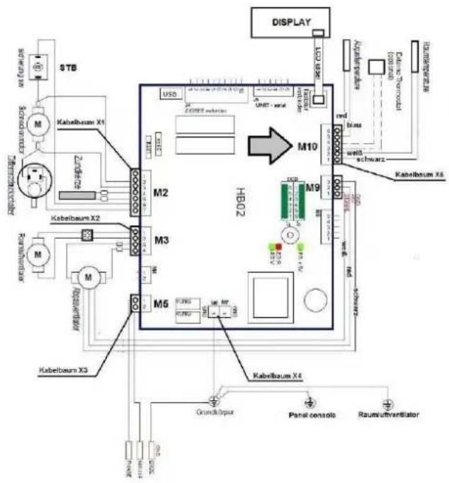
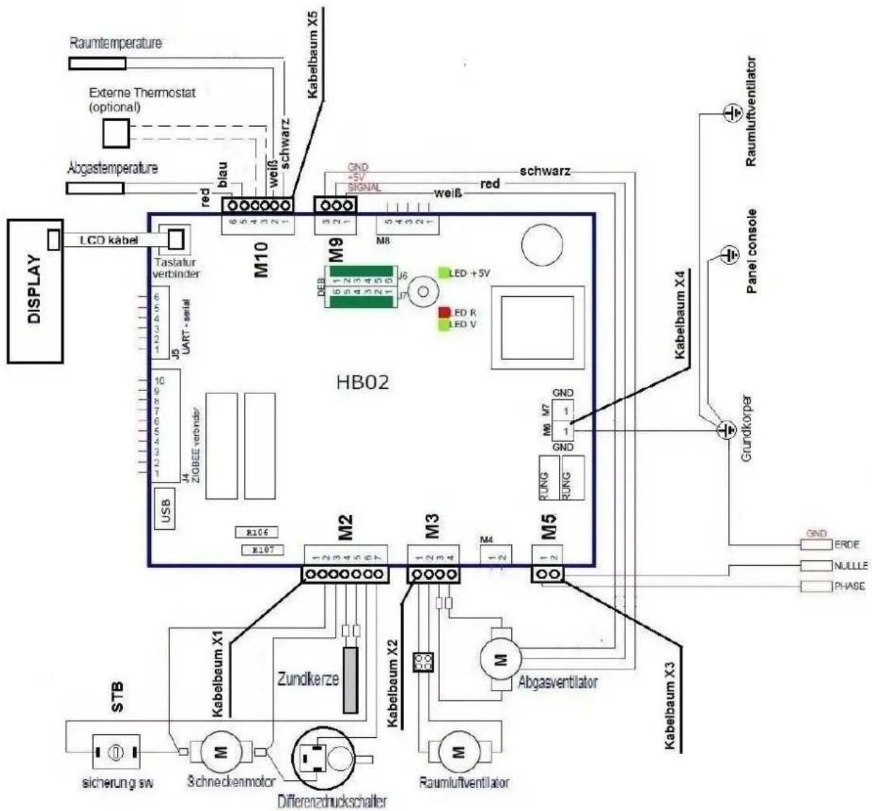
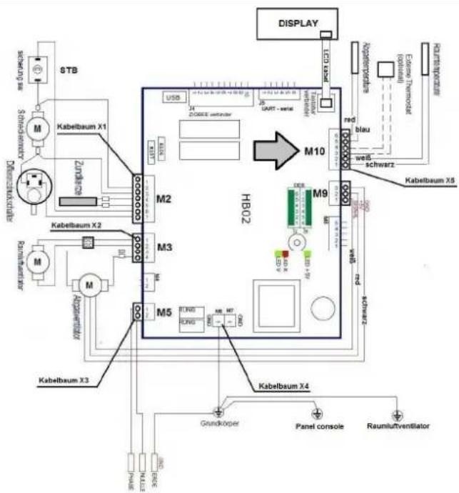
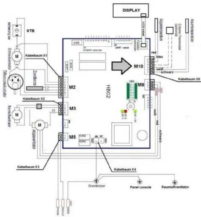
- SCALE DRAWING, CABLING DIAGRAM
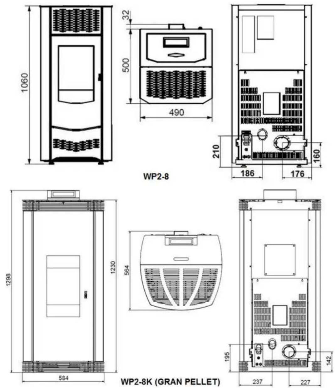
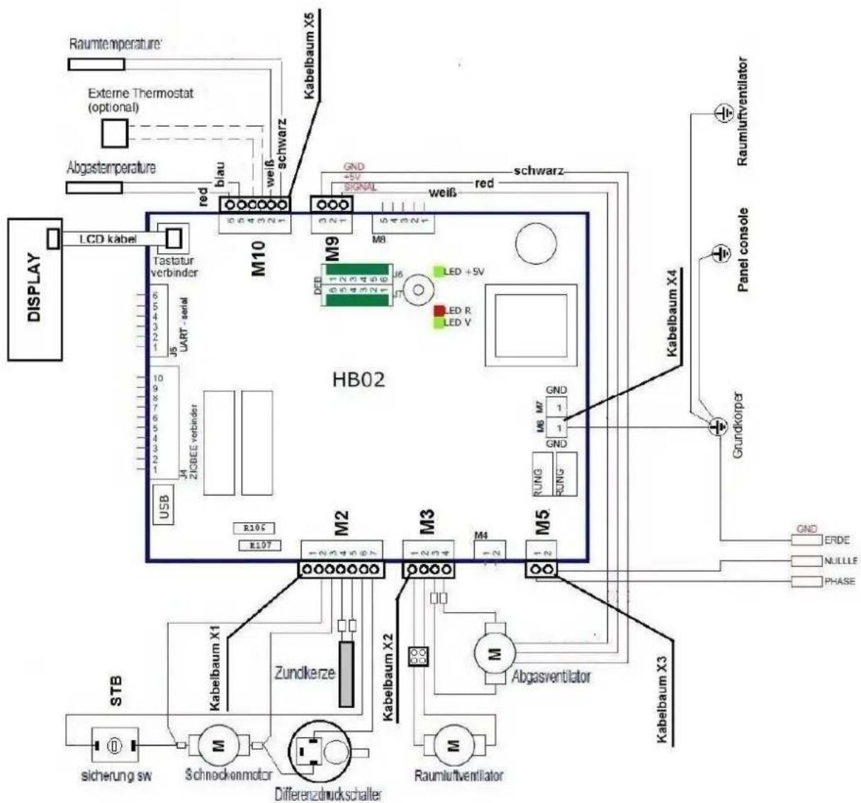
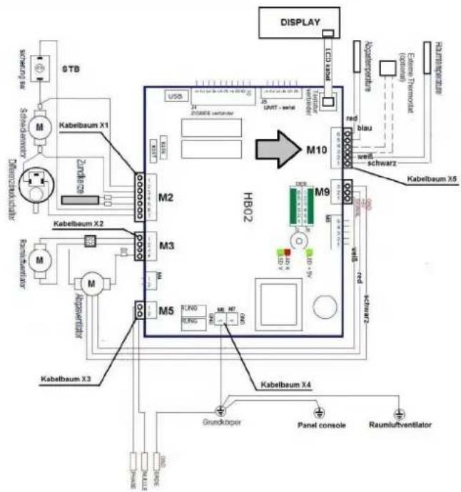
Sicherung - fuse
Schneckenmotor - worm wheel engine
Differenzdruckschalter differential pressure switch
Raumluftventilator - room air fan
Phase - phase conductor
Raumtemperature - room temperatures
Externe Thermostat.... external thermostat (option)
Abgastemprature - exhaust gas temperatures
red - red
blau - blue
schwarz - black
weiss - white
Panel console - panel support bracket
Grundkörper - base
Verbinder - connector
Signal - signal
Tastaturverbinder - keyboard connector
Zündkerze- ignition plug
3. SYSTEM REQUIREMENTS
Our appliances are always connected to other equipment / products of the construction industry, and therefore, as for all technical products, there are certain system requirements in connection with undisturbed operation. Hereunder, a few important requirements are specifically detailed. The list below has not been intended to be all inclusive. All the instructions / data mentioned above shall also be taken into consideration. In advance, the operation of the equipment has to be planned thoroughly by a specialized company so that the individual system components should be accurately aligned with each other, and the intended full-scale solution should be realized.
3.1. MINIMUM OPERATING TIMES / APPLICATION OF EXTERNAL REGULATORS
The pellet is a solid fuel whose ignition takes more time than that of any liquid or gas fuel. Until the appearance of the first flame, a few minutes elapses after startup. The equipment can be operated at full performance after the completion of the warm-up program. When the appliance is switched off, it takes a few minutes – unlike gas or oil combustion – until the pellet burns off, and the flame dies out. For this reason, the appliance is programmed with a few minutes of fan follow-up operating time (see the "INFO" message on the display) that has to elapse until the boiler can be turned on again.
Therefore, the minimum operating time needs to be considered when the appliance is regulated with any external controller. For this reason, the follow-up operating time is programmable among the control options (to be set under the "INFO" menu). When the controller reaches the rated temperature, then the boiler continues to operate for the follow-up operating time before the commencement of the burn-off mode. (This function can be set optionally in the menu.)
All the appliances are designed for operation solely in residential rooms, where normal humidity and temperature in the range from +5°C to +30°C prevails (ambient temperature during operation).
Boilers are not protected against splashing water, and cannot be installed in humid rooms. Because of the operating noise of boilers and the noise caused by the flames, the installation of boilers is not recommended in bedrooms and rest rooms. During operation, falling pellets may cause noise, burning may occur, or the noise caused by flow mechanisms and drive engines may be heard. When the temperature is <5\ °C (for example, in holiday homes), the appropriate minimum settings have to be performed on the boiler, and furthermore adequate freezing inhibitors (for instance, electric heating) shall be provided. When operating at >25\ °C temperature, safety equipment is necessary. See the requirements pertaining to the heating mode in the operating instructions of the appliances.
3.3. CONNECTION TO CHIMNEYS
It is mandatory to have the appliance connected to a chimney that is suitable for use with solid fuels. The connecting profile has to be made from metal. Your competent chimney sweeping company will be pleased to provide you with advice. With multiple loading (operation of pellet-fueled equipment via a single chimney), in Germany the requirements of Standard DIN 18896 have to be observed. The carriage pressure (chimney draft = vacuum) shall be in the range from 6 Pa to 15 Pa (with 12 Pa being the rated value). Before installing the boiler, the chimney planning routine always has to be performed as per Standard EN 13384 so that the chimney could be loaded up to 400°C at the maximum. Especially at times of power outage, the chimney has to ensure the safe carriage of the flue gas from the appliance, and therefore the chimney has important safety functions. When the chimney draft is too large, the incorporation of a draft regulator is recommended. See Section 10.6.
3.4. SUPPLY OF THE COMBUSTION AIR
The appliances operate as depending on the room temperature. Proper combustion air supply is absolutely necessary. There may not be any shortage of pressure in the room of installation. For this reason, in the case of combined installation and operation with air engineering equipment (for example, ventilation equipment, vapour exhausters, pneumatic conveyors, etc.), the relevant technical rules / requirements of the combustion decree (in Germany, Article 4 of FeuVo) have to be observed.
When the boiler is operated in combination with air engineering equipment, as depending on the room temperature, then provisions shall be made for the mutual closing of the devices, or such air engineering equipment needs to be incorporated that is permitted to be operated with solid fuels. In the room of installation, sufficient combustion air (approximately 25-30 m³/h) shall be conducted to the appliance.
3.5. QUALITY OF THE PELLET
Within the meaning of the 1st Federal Emission Protection Decree (1. BlmSchV), solely natural wood pellet can be used in Germany. The quality of the pellet has a crucial influence on the cleaning and maintenance cycles.
All our data and control values have been given as relating to pellet of 0.25 percent ash content, 650kg / m3 specific weight and Hu > 4.9kWh / kg calorific value. As a result, the energy content of 500 liters of fuel oil corresponds to the energy content of 1000kg of wood pellet of the above quality. To store 1000kg of pellet of the above quality, approximately 1.54m3 volume is necessary. Deviations from the above-specified values cannot be avoided within the standard tolerance limits relating to the pellet (such as the ones defined in ENplus-A1, DIN-PLUS, DIN 51731 or Ö-Norm M7135), in association with, for instance, the ash content, specific weight, composition and size/geometry, which evidently leads to differences in the various data.
For instance, when ash content is doubled from 0.25% to 0.5%, the cleaning and maintenance frequency will become halved. According to Standard DIN 51731, the pellet distributed in the market can have ash content of even 1.5%. In the case of such worse quality, the cleaning and maintenance intervals drop to the sixth of the standard value! For the boilers we distribute, the ash content of the pellet is by far the most important value. We recommend the application of such pellet quality in our appliances that is tested under Standard ENplus-A1, DIN PLUS or Ö-Norm 7135, and their ash content is < 0.7%.
The average ash content of commercially available, good quality, branded pellets is < 0.3% on the average.
Ask your own pellet supplier about the ash content of the delivered pellet. The smaller it is, the better you can use it. Due to the allowable natural binding agents used as additives, the pellet ash still can solidify in the combustion chamber, in spite of the tests performed according to the above standards. For this reason, the application of binding agents containing silicate, such as potato starch or corn starch, are not recommended. In this respect, consult your pellet supplier again. In the case of any large specific weight, special geometry and large calorific value, the internal safety equipment can reduce the performance of the boiler on a temporary basis, until it reaches the level of the rated performance. It does not indicate any failure. The appliance modulates itself.
In the case of pellets of very small specific weight or excessively small calorific value, the equipment may remain under the specific rated performance values or performances ranges. It does not mean any malfunctioning, but is caused by the conditions of the fuel. The specialized company can set the boiler to operate with fuels of various conditions and different pellet qualities. It is forbidden to burn shredded wood or other fuels, wastes. If the boiler is operated with unpermitted fuels, then all the warranty and guarantee demands will become invalid, and hazardous operating conditions may occur. Do not experiment with other fuels!
The allowable diameter of the pellet is in the range from 5 to 7 mm. The average length of the pellet may not exceed 30 mm. Pellets of large dust contents (> 5%) cannot be used, either.
3.6. CLEANING, MAINTENANCE AND CARE
Unlike with liquid and gas fuels, solid fuels always generate ash and soot. The quality of combustion and handling comfort of pellet boilers are far better than those of similar boilers operated with shredded wood, yet the burning pan is to be cleaned (by the operator) with shorter intervals, while maintenance and checking become necessary less frequently in order to remove soot and ash from the equipment. If it is not performed, the boiler may malfunction, foe which we cannot assume liability. Regular care, cleaning and maintenance help to preserve the efficiency of your equipment, as soot is an excellent insulating agent, and therefore it considerably reduces heat dissipation and effectiveness, while unnecessary emissions to the environment can also be avoided. Cleaning interval: the combustions chamber has to be inspected visually, and manually cleaned as necessary.
Maintenance interval: Use of 1500 kg of pellet (featuring 0.25% ash content). See also Section 3.5 and 8 of these instructions.
3.7. ELECTRIC POWER SUPPLY
230 V AC / 50 Hz (allowable range of fluctuation: 195–255 V).
See also the provisions of Section 7 of these instructions.
4. THE APPLIANCE AND THE DESCRIPTION OF ITS OPERATION
4.1. TECHNICAL SPECIFICATIONS
| WP2-8A WP2-8KA | |||
| maximum rated heat output | kW | 7.5 | 6.5 |
| minimum rated heat output | kW | 2.5 | 2.5 |
| maximum fuel consumption, approximately | kg/h | 1.9 | 1.6 |
| minimum fuel consumption, approximately | kg/h | 0.6 | 0.6 |
| efficiency (NWL) | % | 90.5 | 90 |
| efficiency (under partial loading) | % | 95 | 96 |
| chimney draft (min.) | Pa | 6 | 6 |
| chimney draft (max.) | Pa | 12 | 12 |
| capacity of the pellet tank, approximately | kg (liter) | 21 (32) | 21 (32) |
| connection to the electric power supply network | V | 230 | 230 |
| frequency | Hz | 50 | 50 |
| maximum power consumption | VA | 350 | 300 |
| diameter of the exhaust gas stub | mm | 80 | 80 |
| weight, approximately | kg | 96 | 94 |
Important note:
Immediately after the commissioning of the equipment, from the rating table record the manufacturing number of the boiler, and keep the invoice. In guarantee-related cases or for subsequent parts supply, the article number and manufacturing number of the boiler are always needed so that the suitable spare parts can be delivered to you. Without knowing the manufacturing number and the date of purchasing, we cannot accept guarantee-based performance, and the option of defective supply cannot be excluded, either. All the documents provided with the equipment shall be kept carefully, as it promotes the work of customer services when required, and facilitates the situation of the future owner of the equipment.
After purchasing, note down manufacturing number of your equipment:
4.2. SCOPE OF SUPPLY
The scope of supply covers the following appliances:
- Heat-resistant gloves, accessory tool to open the door, operating instructions.
4.3. DESCRIPTION OF THE OPERATION
WAMSLER pellet boiler is a special heating equipment for household use, and is suitable for burning only 6 mm ∅ wood pellet as described in Standard ENplus A1. The heating mode the equipment produces hot air, which radiated to the room. To use the heating option, simply switch on the boiler, and choose the desired performance grade. When an external regulator is used, the pellet-burning boiler automatically switches on and off, and the performance grade can also be modulated automatically. Wood pellets are fully automatically carried by the equipment to the combustion chamber, and ignited by means of electronic ignition.
Corresponding to the selected performance grade, the controlled conveyor worm transfers the appropriate fuel quantity. The air needed for combustions flows to the combustion chamber in a controlled manner. The gas burns in the combustion chamber and the connected flue gas discharge units, and transmits its energy to the environment.
At the ends of the hot gas passages, an exhaust fan can be found that safely conducts the outlet gases to the chimney as appropriate for the quantity of fuel and volume of combustion air. The operator is required to clear the ash and cinder from the combustion chamber at regular intervals. The inspection window shall also be cleaned from the deposited ash, which is always generated when solid fuels are burnt. The hot gas passages also have to be maintained regularly. It needs to be carried by a specialized company.
Solid fuels naturally leave soot behind, and therefore the contamination of the inspection window cannot be fully avoided, but it does not represent any deficiency.
Before being installed in the residential spaces, boilers have to be planned, reviewed and authorized. For burning, the inflow of a sufficient volume of oxygen needs to be ensured. For this reason, boilers can be operated with air engineering equipment – such as vapour exhausters, ventilation equipment or pneumatic conveyors used for the carriage of wood pellet – only under specific conditions. Consult any associated issue with the locally competent chimney sweeping company or specialized contractor.
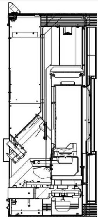
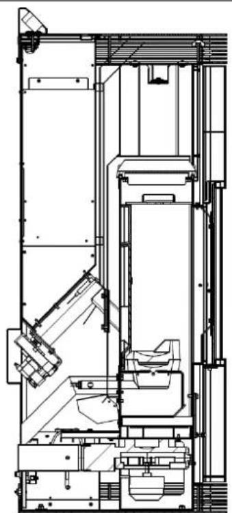
Cross-section of operation
| WP2-8A | WP2-8KA (GRAN PELLET) |
| with a convectional fan without a convectional fan | |
4.4. FIRST COMMISSIONING
Important instructions:
• Always keep the door of the combustion chamber closed, even when it is cold.
- In heating made, all the surfaces can become extremely hot, especially the inspection windows, handles and control elements. Call the attention of children, young and elderly people to this threat, and ensure that the animals that may be in the surroundings should not be injured. Ensure that no one should be in the hazardous vicinity of the boiler when it is in operation. To handle the boiler, use the protective gloves or accessories provided with the equipment. In the absence of a supervisor, children and young people under the age of 16 cannot operate the boiler.
- In continuous operation, your clothes may as well become hot. Use the heat-resistant protective gloves provided together with the equipment.
- All the parts of the boiler made from steel or cast iron have been coated with heat-resistant varnish, which has been burnt on the metal. When a new pellet boiler is first heated up, the varnish still in the process of drying, and therefore smoke and unpleasant smell can be generated! In this respect, it is worth accepting the following advice:
- Ventilate the room thoroughly in order to discharge the released steams.
During the period of hardening, the varnish is still soft. Do not touch the varnished surfaces to avoid damage to them.
○ After operation at high heating performance, the hardening of the varnish becomes complete.
When the equipment has been completely equipped in line with the installation instructions, then pellet can be fed into the storage tank. Fill at least 5 kg wood pellet into the storage tank.
At this time, no other objects can be in the pellet tank, the combustion chamber or at the burner.
Filling the supply tank
Open the cover of the tank. Tear the seam of the pellet bag open, and with its opening looking downwards let the bag down to the screen grid, into the supply tank, and finally slowly discharge the contents of the bag into the tank. After filling, close the cover of the tank, which shall be always kept closed during operation.
Our recommendation: Pour the pellet slowly into the tank from just a little height, because it would generate less dust. The pellet can be filled into the supply tank with the use of a bucket or similar tool, as well.
Important: ACT CAUTIOUSLY when filling the tank! The pellet bag may not come in contact with the pellet bag. Immediately remove the pellet that has not entered the tank!
Warning! Foreign bodies may not be dropped into the supply tank, and therefore the associated damage is not covered by our guarantee / warranty.
Procedure to switch the appliance on
At the time of the first commissioning the conveyor worm is still fully empty. After first switching the appliance on, it takes some 10 minutes to have the first pellets falling into the burner pan, and then ignition switches off again. The same applies to the case when the supply tank is filled up too late, and the equipment operates fully empty.
Procedure to ignite the equipment safely:
- Turn the equipment on with the I/O switch, and then wait for the heating program to complete, and the first pellets to fall into the burner pan.
- Turn the appliance off instantly with the use of the I/O switch, and then reset it after 5 seconds. The warm-up program is completed again, and when the first pellets fall into the burner pan, the appliance ignites. The ignition program has to be repeated as required.
Our recommendation:
When the supply tank has become fully empty, and there is no pellet in the conveyor worm, the time period needed for feeding pellet to the burner pan again, and igniting the appliance by transferring a handful of pellet to the burner pan via the first row of holes.
Warning! The burner pant should not be completely filled, as it may result in malfunctioning!
4.5. BEFORE STARTUP / IGNITION
Important: The process of ignition can take up to 10 minutes after the visible appearance of the first flame (as depending on the cleanliness of the burner pan), the equipment restarts after each resetting or power outage.
- Open the door of the combustion chamber. Ensure that there is no contamination or pellet in the burner pan and the combustion chamber, and clear the pellet, ash and cinder off the burner pan.
- Close the doors.
- Switch the equipment on with the use of the I/O keys. Start feeding the pellet to the burner pan. The ignition element of the equipment performs ignition automatically. The pellet starts burning in 5–10 minutes at the latest.
- If no ignition occurs (the pellet does not burn in the burner pan), then examine the contamination of the burner pan first (with all the ventilation openings being unobstructed), and whether the supply tank has been filled. Or pass the pellet through the worm, which takes approximately 10 minutes if it is the first time the appliance is switched on, or the supply tank has become fully empty. Before restarting, fully clean the burner pan. When the startup process has failed, fully empty the burner pan, and remove the pellet that has not burnt off and the ash. It is prohibited to feed back any unburnt pellet into the supply tank again, or ignite it in the burner pan.
• → They pose fire hazards due to the glowing residual materials and/or overheating! ←
4.6. OPERATING AND HEATING MODE
There are various keys to operate the appliance, completed by displays and indicators. In general, the appliance can be operated with the I/O key, as well as the "+" and "-" keys.
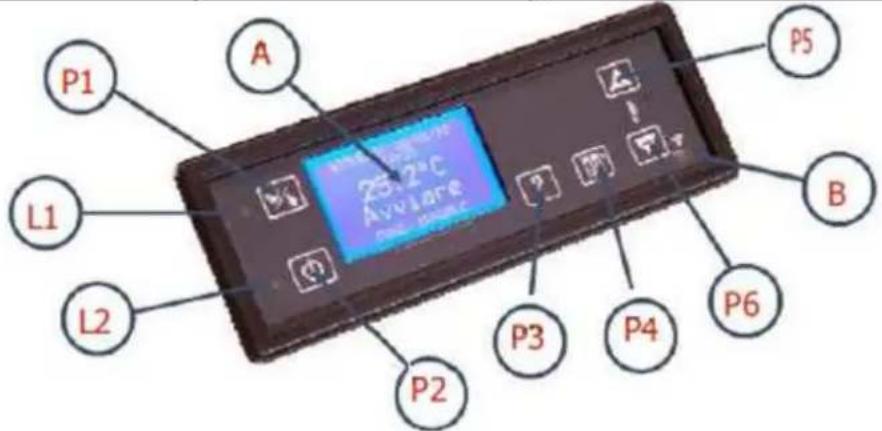
P1 Press to enter the timer menu.
P2 ON / OFF - key
P3 HELP - key
P4 SET - key – Press to enter the - "Change parameters" menu
P5 "+"- key - increase
P6 "-" - key - decrease
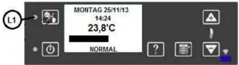
L1 LED - thermostat - ON - OFF
L2 LED - operation - ON (even when it is not active) - OFF (the system is in OFF (AUS) status)
A display / screen
B Red-ray remote control (inactive)
Setting the contrast of the screen
It is possible only in the main menu. Press P5 to increase, and the P6 key to decrease.
Illumination of the screen
It is possible only in the main menu. To increase or decrease the illumination, press the P3 key concurrently with P5 or P7.
Changing the temperature
Press the P4 key until the menu shows the room temperature. To change the values, press the P5 or P6 keys (this menu setting is not available when an external thermostat has been activated).
Access to the Chrono – Thermostat menu
Press the P1 key for approximately 5 seconds.
HILFE (HELP) – key (P3). Information by pressing the P3 key can be displayed for approximately 10 seconds.
For the ON / OFF function, press the P2 key for approximately 3 seconds.
Open the information pertaining to the boiler
Press the P1 and P2 keys concurrently. The equipment status appears on the screen. Press the P4 (MENU / SET) key for approximately 5 seconds.
Use the P5/P6 keys to select the menu to be preferred.
Press the P4 (SET) key to make your selection. Press the P5 and P6 keys to change the settings.
4.7. TEMPERATURE MENU
The menu functions can be changed with the use of the P4 (SET / Menu) key.
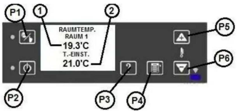
- Current room temperature.
- Set room temperature.
Use the P5 / P6 keys to increase or decrease the set temperature. Press the P4 key to acknowledge the set temperature.
Press the P4 key again to return to the main menu.
4.8. USER MENU
Menu structure:
![graph TD A["TOP MENU"] --> B["CHANGE ROOM TEMPERATURE SET"] B --> C["SET"] C --> D["SET 2""] D --> E["USER MENU"] E --> F["EXIT (to top menu)"] F --> G["PRE-LOAD"] G --> H["SYSTEM STATUS"] H --> I["PELLET LOAD SETTINGS"] I --> J["VENTILATION SETTINGS"] J --> K["GENERAL SETTINGS"] K --> L["RADIO…](/content/2026/04/733739/images/f0dceb5f0cee8016844e1fe34d202d743726fc9ae2263f7b4ff6fc598c5f44a7.jpg)
WP2-8 GB 51 / 192
| Raum T Einstellung | setting the room temperature |
| Menue | menu |
| Set | setting |
| User Menue | user menu |
| Service Menue | service menu |
| key | key |
| and | and |
| Schaltuhr Einst. | setting the timer |
| Quittieren | acknowledgment |
| Pelletzufuhr | pellet feeding |
| Offenstatus | boiler status |
| Pelletsorte-Einst. | setting the pellet quality |
| Raumgebläse-Einst. | setting the room fan |
| Hauptmenü | main menu |
| Schaltuhr-aktiv | timer active |
| Komforttemp. | comfort temperature |
| Normaltempl. | normal temperature |
| Economytemp. | economical temperature |
| Schaltzeitenprog. | programming the times for switching on date/precise time |
| Datum/Uhrzeit | |
| Fernbed...... | remote control (yes/no) |
| Sprachwahl | selection of the language |
| Störungscode | error codes |
| Wartung | maintenance |
| Foerderd. Menu | supply menu |
| Abgassensoreinst. | setting the exhaust gas detector |
| Werkeinstell. | factory setting |
| Funtionstest | operating test |
| Parametereinst. | setting the parameters |
| Zufuhrtest | feeding test |
| Fernbedienung | remote control |
| password | password |
Enter the use menu by pressing the P4 key for longer (approximately for 3 seconds).
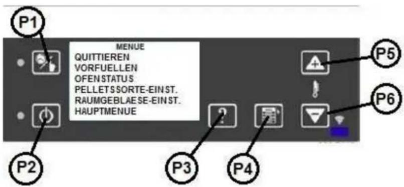
Quittieren: return to the main menu
VORFUELLEN: PELLET FEEDING function
(it can be set only when the appliance is switched off, two setting options are available)
OFENSTATUS: information on the current status
PELLETSORTE-EINST.: setting the pellet quality
RAUMGEBLÄSE-EINST.: setting the room temperature fan within the allowable limits
HAUPTMENUE: setting the date /precise time / display / standby mode /
language
4.9. GENERAL SETTINGS
The main menu has two sides, and you can move between them with the P5/P6 keys:
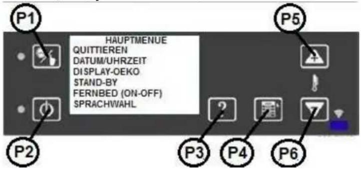
First menu page:
Quittieren: return to the main menu
DATUM/UHRZEIT: setting the precise time / date
DISPLAY DEKO: activation / inactivation of the duration of the lighting of the display
STAND-BY: activation / inactivation (switching off) of the Standby function
FERNBED. (Y/N): activation / inactivation of the remote control (it does not belong to the scope of supply)
SPRACHWAHL setting the language (DE/IT/HU)
Second menu page:
STOERUNGSCODES: Displaying the registered fault reports (ALARMS) that are stored in the log file.
WARTUNG: Information of the maintenance
4.10. SETTINGS MAIN MENU
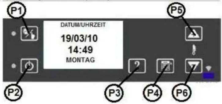
DATE / PRECISE TIME
Enter this menu by pressing the P4 key shortly.
These values can be set with the use of P5 and P6 keys. It is not necessary to set the weeks of the day.
Return to the menu by pressing the P4 key longer.
DISPLAY OFF
The P4 key activates/inactivates the display mode in case no other key is pressed for 300 seconds. These values can be set with the use of P5 and P6 keys.
STANDBY
Select and press the P4 key shortly to enter this menu.
The values can be set by using the P5 and P6 keys, while the P4 key has to be pressed shortly for acknowledgment and exit.
FERNBEDINUNG (J/N) / REMOTE CONTROL (YES/NO)
Select and press the P4 key shortly to enter this menu.
The values can be set by using the P5 and P6 keys, while the P4 key has to be pressed shortly for acknowledgment and exit (not available).
SPRACHWAHL / LANGUAGE SELECTION
Select and press the P4 key shortly to enter this menu.
The values can be set by using the P5 and P6 keys, while the P4 key has to be pressed shortly for acknowledgment and exit.
5. START
Pressing the P2 (ON/OFF) key for approximately 2–3 seconds.
The program automatically examines the following conditions.
INITIAL CLEANING CONDITIONS
Operation of the exhaust fan for 5 seconds.
HEATING CONDITIONS
Ignition switches on with the exhaust gas fan. Duration: 180 seconds.
FULL LOADING CONDITION
The worm switches on together with the exhaust gas fan for 60 seconds.
STAND-BY CONDITION
The worm stops for 120 seconds (PA04 parameter) in order to facilitate the ignition of the pellet.
CONDITION OF SWITCHING ON
The exhaust gas fan and worm are active for 1500 seconds.
Transmission to the next phase occurs only when the temperature of the exhaust gas rises over the smallest allowable value (50 °C).
If this phase does not occur within the allowable 1500-second interval, the pellet boiler enters into alarm status due to the lack of ignition.
STABILIZATION CONDITION
After reaching the 50° C minimum temperature, the ignition switches off. One has to wait for the prescribed flame stability, and a temperature rise of at least 3° C/minute. This status lasts for approximately 180 seconds.
If this condition does not occur, the boiler enters into alarm status due to the irregular flame.
OPERATING CONDITION
The boiler switches on the room temperature fan at 90° C exhaust gas temperature.
OPERATION
The pellet boiler starts to operate.
TIMER (setting of the timer)
With the timer function, the boiler can be programmed for a week in advance. (Boiler IN, OFF / temperature settings: comfort, normal, eco.)
To open the menu for setting the timer, press the P1 key for 3 seconds.
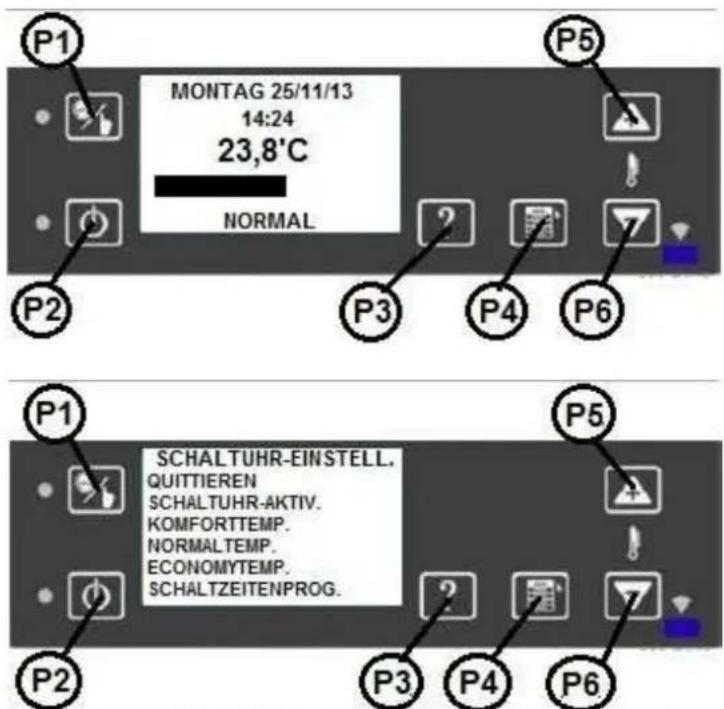
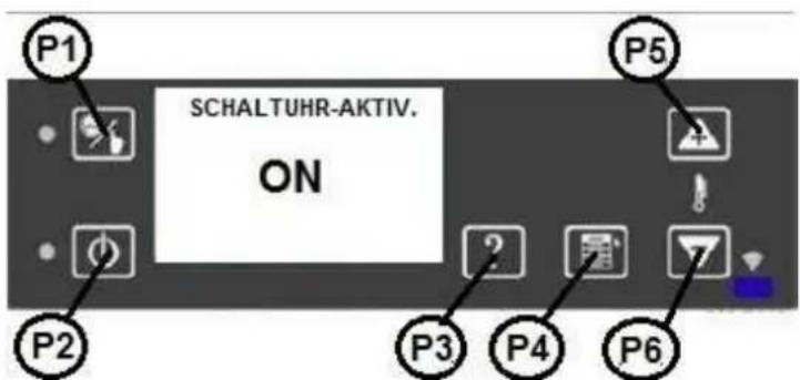
To activate the timer setting: "SCHALTUHR-AKTIV." (P4, P5, P6 keys).
The L1 LED is on.
5.1. REACHING THE TEMPERATURE (TEMPERATUR) VALUE
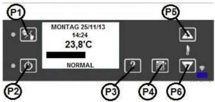
The boiler consistently keeps the set temperature, and after reaching the set value it guarantees the best conditions for the users without major performance fluctuations and minimum energy consumption.
Performance is presented on the screen by a band chart. This chart also indicates room temperature.
SETTING THE TEMPERATURE
The menu allows the setting of three temperature values: COMFORT, NORMAL, ECONOMY. For each of these settings, a programming window is available.
The following example pertains to the COMFORT temperature setting:
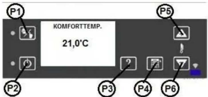
With the use of the A P5/P6 keys, increase or decrease the temperature range. Keep the P4 key pressed for long.
5.2. SETTING THE TIMER
See the graph below:
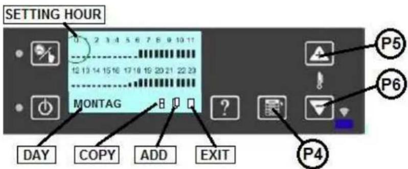
The graph shows all the days of the week. The DAY field is split up into 24 periods, each of these periods lasts for 1 hour (1, 2, .... 24). Each of these hours is divided into two periods of 30 minutes.
Selection of the functions and hour ranges
By pressing the P5 and P6 keys, symbols can be reached in both directions (hours, days of the week, programming symbols of "copy, add, exit").
Here, the desired ranges can be selected, such as the 7:00 time (see the graph).
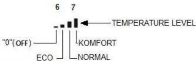
TEMPERATURNIVEAU
TEMPERATURE LEVEL - TEMPERATURE LEVEL
KOMFORT - COMFORT
NORMAL - NORMAL
ECO - ECONOMY
TERMPERATURNIVEAU - TEMPERATURE LEVEL
By pressing the P4 (SET) key continuously, set the black column to the desired height (0 "AUS", ECO, NORMAL, COMFORT).
For instance, the boiler switches off at 6:00 (OFF), turns on at 6:30 in ECO mode, at 7:00 it start to operate on the NORMAL performance level, while at 7:30 it works in COMFORT mode.
The times can be set with the use of the P5 and P6 keys.
Modification of the days of the week
The days of the week can be set with the use of key P5 and P6. The days of the week can be set by pressing the P4 (SET) key. The days of the week appears one after the other.
After selecting the day, the times can be set with the use of the P5 and P6 key in the above-specified order.
For each day, multiple switching on and off cycles, as well as various temperature values can be programmed.
The following page describes how to copy the settings of a specific day to another day.
Copying the settings of the day of the week:
With the use of the P5 (next) or P6 (back) key, set the times, and then go to the copy symbol, press the P4 (SET) key to copy the settings.
By pressing the P6 (back) key to return to the day of the week, and then press the P4 key select the day for copying the given values.
With the use of the P5 (next) key, go to the Add symbol, and then press the P4 (SET) key.
This procedure can be repeated for each day of the week to which the settings have to be copied.
To exit from the copy function, press the P5 (next) or P6 (back) key, go to the exit symbol, and press the P4 (SET) key again.
Example according to the figure:
The boiler switches on at 6:30 on level 3 (COMFORT).
At 12:00, the boiler switches off, and remains in this status until 17:30.
At 17:30, the boiler switches back on level 1 (ECO).
At 18:00, the boiler changes performance, and switches over to level 2 (NORMAL).
At 18:30, the boiler changes its performance, and switches over to level 3 (COMFORT).
Programming remains ineffective, when the boiler is switched off (OFF) (the LED is ON).
WARNING! The programming field can be switched on even if the boiler is switched off (OFF); at this time, the boiler can be controlled with the use of the programming field.
5.3. DISABLING THE AUTOMATED MODE
By default, the fireplace operates in AUTOMATED performance regulation mode.
It means that the control unit adjusts the heating performance of the fireplace automatically to reach the set temperature. In this case, the difference between the room temperature and the set temperature decides the optimum performance at which the device needs to operate.
If the AUTOMATED mode is switched OFF, then the user may choose from 5 pre-defined performance grades:
L1 cc. 2–2.3 kW
L2 cc. 4–4.3 kW
L3 cc. 6.5–6.9 kW
L4 cc. 7–7.2 kW
L5 cc. 7.2–7.5 kW
The fireplace continues to operate at the selected performance grade until the temperature of the room reaches the set value.
After reaching the set temperature, the control unit shifts to a lower heating grade.
To disable the AUTOMATED mode, follow the procedure described below:
First keep the P4 button pressed
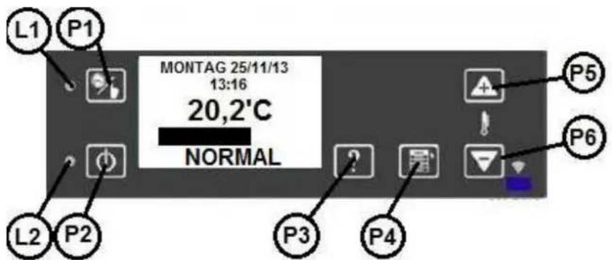
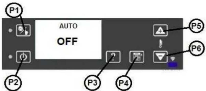
With the use of the P5–P6 buttons, set switch from ON to OFF.
To exit, press the P4 button twice.
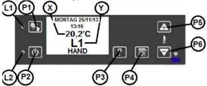
Now, the following main menu appears, showing the currently set performance grade:
In the following example:
X: The current room temperature is 20.2°C.
Y: The fireplace operates at L1 heating performance.
Adjustment of the performance grade:
To enter the adjustment menu, press the P4 button.
The page displays the following information:
X: Set heating performance grade
Y: Current heating performance grade
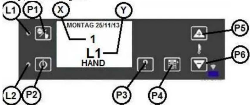
To increase or decrease the heating grade, press the P5 or P6 button, respectively.
Following the modification, after a short time the fireplace switches to the set grade.
By pressing the P4 button, enter the room temperature adjustment page:
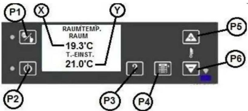
X: Current room temperature
Y: Set room temperature
The room temperature can be adjusted with the use of the P5 and P6 buttons.
Return to the main page by repeatedly pressing the P4 button.
5.4. DISCHARGING/CHARGING THE PELLET TANK
The pellet consumption of the fireplace depends on the set performance grade. Check at least once a day whether its quantity is sufficient.
In case the tank is fully empty, then the "NoPellet" error message appears on the screen. In this case, use the P2 button to confirm the message, and fill the tank. Press the P2 button to restart the device.
Warning!
When the device is first started up, or the tank has become fully empty, the re-ignition of the fireplace takes longer, because in these cases the feeding system should first be fully charged.
It may be necessary to repeat the procedure of starting. In this case, the screen shows the "2." message.
This message warns that the starting procedure has to be repeated by keeping the P2 button pressed longer for two times.
If the fireplace is not restarted within 15 minutes, the F01 (unsuccessful ignition) error message appears.
IMPORTANT INSTRUCTION!
Before starting, always ensure that the burning pot should be fully empty, meaning that it may not hold even ash or pellet, because the clogged burning pot leads to malfunctioning.
It is essential to check the burning pot regularly during programmed operation.
These checks are recommended to be performed in the programmed operating breaks.
ENABLING / DISABLING THE "BEEP" AUDIO SIGNAL:
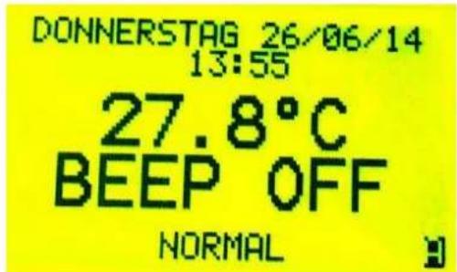
Default setting: "Beep" audio signal OFF.
Enable the audio signal as follows:
The fireplace has to be switched off.
- On the main screen, keep the P3 button pressed (for 3 seconds).

- The following message appears on the display:
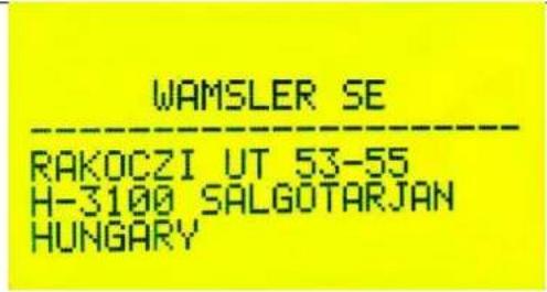
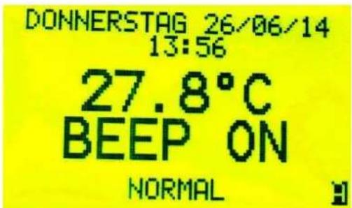
- Immediately push the P1 button, and the display shows that the "BEEP" has changed to ON:
To disable the "BEEP", repeat the three steps, and then the following screen appears:
6. STAND-BY (SWITCHING OFF)
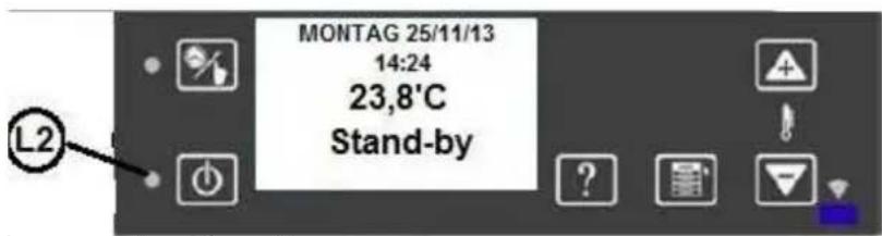
After activating the STAND-BY mode and reaching the set room temperature (*), the switches off, and remains in this mode.
Within 5 minutes, when the temperature exceeds the room temperature by 2° C, the boiler switches over to STAND-BY mode.
The STAND-BY status is indicated by the LED light (L2).
In this mode, the boiler still operates, and switches on actively only when the set room temperature drops by 2° C, and the appliance remains in this status for at least 10 minutes.
(*) when the room temperature is active.
6.1. BOILER SWITCHES OFF
The boiler can be turned off at any time with the use of the P2 key (ON/OFF).
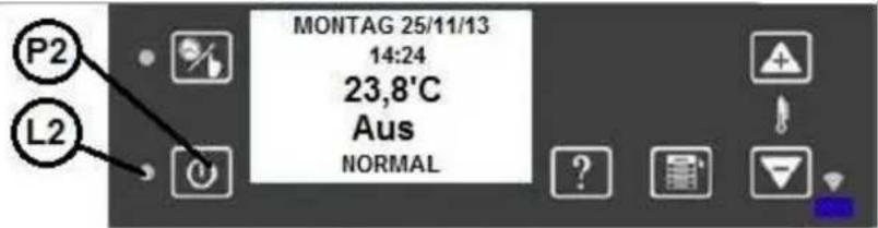
When the boiler has been turned off, the green LED keeps flashing until it is fully switched off (OFF).
INACTIVE STATUSES
When the P2 (ON/OFF) key is pressed to turn the appliance off, the goes to SWITCH OFF status, and then switches over to cooling down.
The exhaust gas fan switches to the highest grade in order to burn all the pellets in the combustion chamber.
The following status can be reached only when the temperature of the exhaust gas does not exceed the 70°C limit value.
COOLING DOWN
The exhaust gas fan remains in switched on status for 300 seconds.
Thereafter, the exhaust gas fan fully switches off (LED L2 in OFF status).
POWER OUTAGE
In the case of any power outage not longer than 10 seconds, the boiler continues to operate. When the boiler is in STAND-BY mode, it switches back in this mode.
In all the other statuses, the boiler switches off when there occurs power outage.
PRESSURE DROP (pneumatic storage tank)
When there is any unforeseeable pressure drop in the equipment, and the pneumatic storage tank opens in the burning phase, then the boiler switches over to "DEPRESSION" status, where the exhaust gas fan increases the speed until the pneumatic storage tank can close again.
When the contact element of the pneumatic storage tank remains open for more than 20 seconds, then the boiler switches over to the alarm status due to the pressure drop.
ALARM
Upon any fault indication, the boiler switches into alarm status after a 60-second delay. If the fault indication is not cleared within the prescribed period, the boiler shifts into alarm status, and switches off. Then, the exhaust gas fan operates at maximum speed.
The memory records all the alarm statuses in the alarm history, with the exception of the "no pellet" status.
| F01 | no ignition | the pellet tank is empty, the quality of the fuel is not appropriate |
| F02 | it is not stabilized too little heat is generated after ignition | |
| F03 | fail in exhaust temperature probe | |
| F04 | fail in room temperature probe | |
| F05 | too high temperature of the printed circuit board let the boiler cool down | |
| F06 | exhaust pressure alarm (chimney blocked) chimney check | |
| F07 | StB, too high internal temperature let the boiler cool down | |
| F08 | exhaust gas fan | contaminated chimney / exhaust gas pipe / boiler, failed fan |
| F10 | worm engine has been operating for more than 40 seconds | |
| F11 | the contact element of the pressure switch closes upon the first inspection | excessive draft in the chimney, failed pneumatic storage space |
| F13 | the temperature of the exhaust gas is too high | |
| “CALL SERVICE” | Call Service | |
6.2. ACKNOWLEDGMENT OF THE ALARM
Press the P2 key (ON/OFF) for short to acknowledge the alarm, or press the P2 keys (ON/OFF) longer to switch the boiler off.
If the equipment cannot be stopped, request help as the case may be.
It is forbidden to unplug the boiler from the socket in the course of operation! The boiler shall be switched off in advance, and the operator shall wait until the fan fully stops (the fuel burns down).
7. ELECTRIC POWER SUPPLY
The equipment may be operated solely from an electric power supply socket provided with protective grounding.
230 V AC / 50 Hz (allowable voltage fluctuation: 195–255 V).
Use only the power supply cord provided as an accessory!
Ensure that the cord should not come in contact with the hot surfaces of the boiler (exhaust gas pipe, etc.).
The connecting cable has to be replaced immediately in case it is damaged, or show damaged parts. Contact our Customer Services to procure a spare cord.
7.1. FUSE REPLACEMENT
Warning! The fuse may be replaced only by qualified personnel!
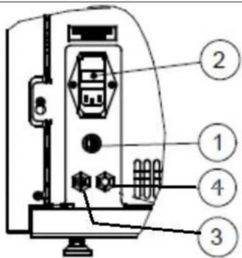
- STB fuse – temperature switch
- main switch, power supply socket, fuse holder
- temperature sensor for room temperature
- external thermostat, input
The fuse may be replaced only in the case of boilers that have been disconnected from power supply!
First, turn off the main switch, and then unplug the power cord from the power supply socket.
The fuse holder (2) disconnected from the power supply socket has 2 fuses of 2.5 A. For replacement, use only the following types of fuses!
Type: 250V/2,5 A (F) 5*20 mm
7.2. RESETTING OF THE SAFETY TEMPERATURE LIMITER (STB)
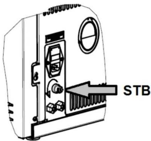
The safety temperature limiter (STB) is a prescribed safety element that switches off the boiler in the event of overheating.
Error code: F07
Reset the appliance manually. Remove the protective cap with the use of the screw, and push the button.
If the button cannot be pushed back, the temperature of the equipment is too high, and one has to wait until it cools down.
7.3. CONNECTION OF THE EXTERNAL ROOM THERMOSTAT
This operation may be performed only on appliances cut off from power supply.
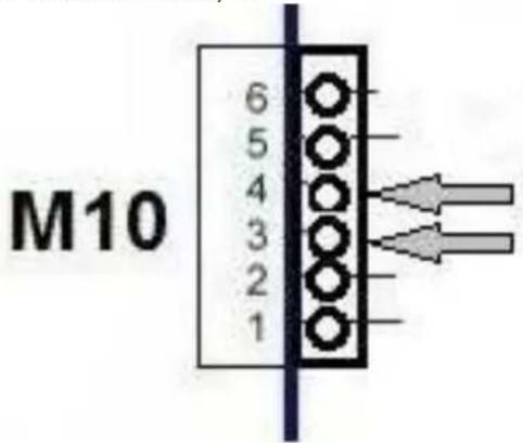
Lead the cable of the external thermostat into the appliance through packing box shown in the picture.
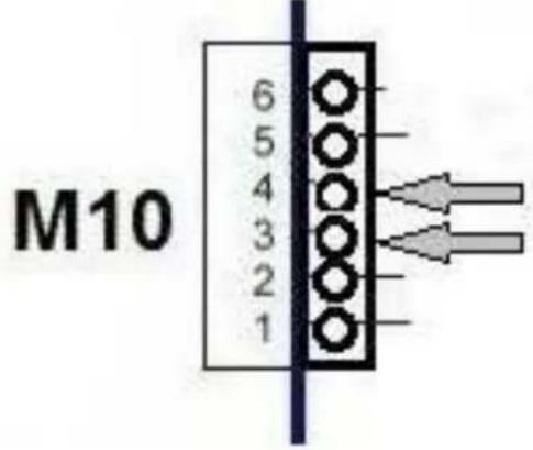
Connect the two wires of the thermo-
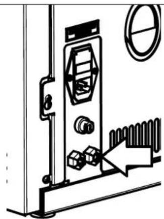
stat into the designated M10 connector to terminal 3, 4.
ENABLING THE EXTERNAL THERMOSTAT IN THE EXTERNAL SOFTWARE
First keep the P4 button pressed (for 3 seconds).
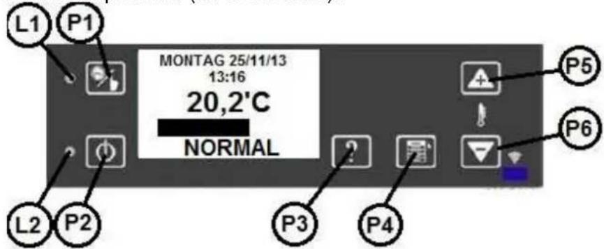
After pressing P4, the following menu is displayed:
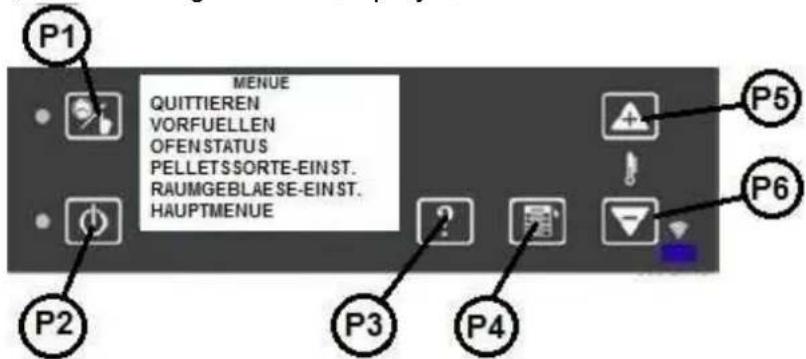
With the use of the P5–P6 buttons, choose the MAIN MENU, and press the P4 button again.
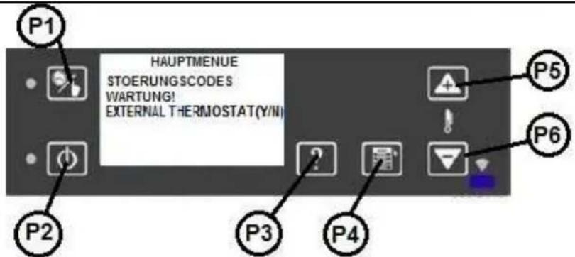
With the use of the P5–P6 buttons, go to page 2, select and enter the "EXTERNAL THERMOSTAT (Y/N)" submenu by pressing the P4 button.
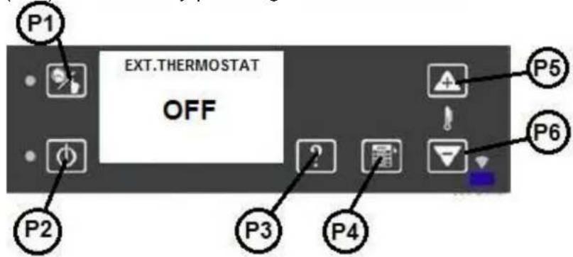
With the use of the P5–P6 buttons, set switch from OFF to ON. To exit, press the P4 button.
8. CLEANING AND CARE
The burning of solid fuels always generates soot and ash. Therefore, it is mandatory for the operator to clean the appliance regularly in order to ensure undisturbed operation.
Warning! / Caution!
It is forbidden to operate appliances that are not kept clean in line with our own requirements. If the cleaning instructions are not observed, all the warranty claims will become invalid.
The necessary frequency of the cleaning of the burner pan is solely dependent on the ash content of the pellet, and cannot be changed by any setting of the appliance, because ash is the incombustible component of the pellet!
Therefore, we recommend the use of wood pellet of < 0.5% ash content.
The performance of maintenance calls for a certain degree of expertise, and therefore it is always recommended to have the maintenance works performed by a specialized company.
Warning! / Important!
Fire hazard, short-circuit risk and threats to life!
The equipment may be operated only after all the intended covers have been fitted, otherwise the warranty and guarantee relating to the boiler become void, as there is a risk of contact with parts under voltage or hot elements!
Before the commencement of works, unplug the electric supply connector, and re-plug it to the socket for the purpose of trial operation only when all the covers have been fully and professionally installed.
Warning! Start the cleaning operation only when the boiler has fully cooled down!
Warning! Fire hazard! Glowing residues in the ash always represent fire hazards. Vacuum clean the ash only if your are absolutely certain that there is no glowing fire in the ash.
8.1. INSPECTING AND CLEANING THE BURNER PAN
Please inspect on a daily basis, or on every second day at the latest whether the burner pan holds burning residues (ash/cinder). Clean the burner pan and bore-holes when 30 g ash/cinder has become generated at the latest.
Remark:
When the boiler is operated continuously, switch it off at least twice within 24 hours in order to clean the burner pan. RISK OF FLASHBACK %
The burner pan can be cleaned within a few seconds when operation is paused; for this purpose, use a scraper to pull out the ash from the burner pan, until just a little glowing fire remains. Let the ash simply fall into the ash space.
Important instructions:
- All the openings of the burner pan should always be left free.
- In the burner pan, the ash cannot be mashed or squeezed so that the clogging of the air openings could be avoided.
• After each cleaning operation, ensure whether the burner pan is fitted in the collecting unit appropriately and tightly.
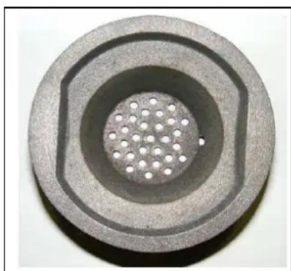
Caution! Fire hazard!
When glowing fire remains in the ash, it represents acute fire hazard. Vacuum clean the ash only if your are absolutely certain that there is no glowing fire in the ash.
WP2-8 F 67 / 192
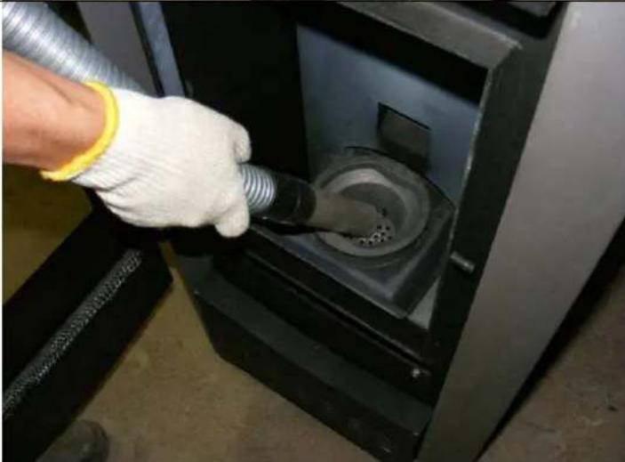
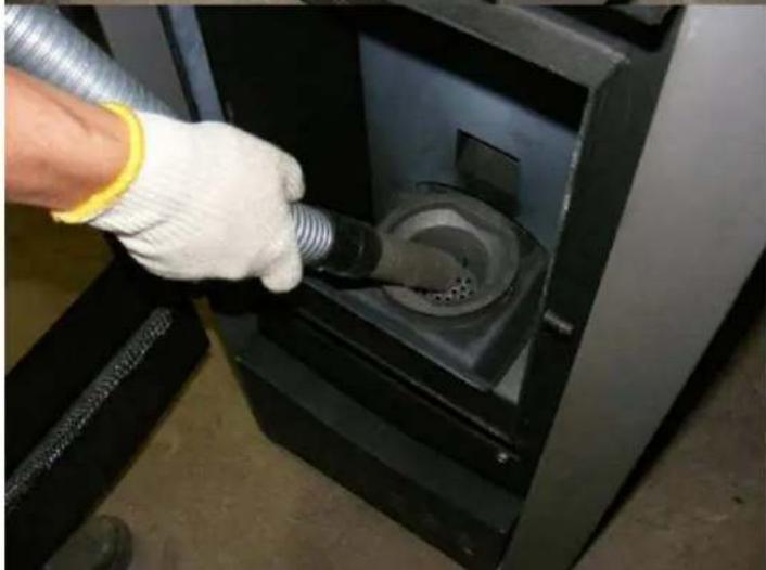
| Cleaning the burner panUse a vacuum cleaner to clean the burner pan, and use a brush as required.Leave all the openings unobstructed, and free from residues. | 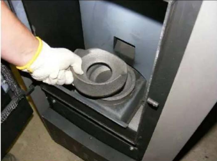 |
 | |
| Cleaning the ash compartmentUse a vacuum cleaner to clean the right/left ash space, as well as the edges of the door of the combustion chamber.Be careful to keep the sealing of the door undamaged! | 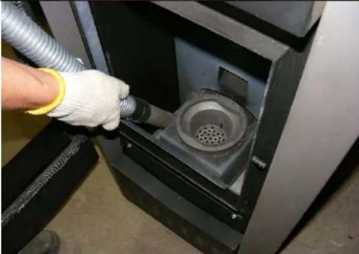 |
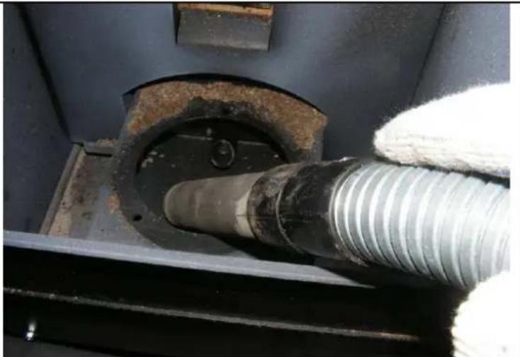
Cleaning the burner pan holder
After removing the burner pan, the holder can be cleaned from deposits.
When the burner pan is installed, pay attention to its proper position!
8.2. CLEANING THE INSPECTION WINDOW
The appearance of vapour on the inspection window is a normal phenomenon, and does not indicate any deficiency.
When solid fuels are used, deposition appears on the inspection hole, especially when the ash of the applied wood pellet is very fine. Depending on the quality of the pellet (especially with small performance), this deposit can be both light and dark. Clean the glass of the doors of the combustion chamber with a with cloth, and remove tenacious contaminations with the use of special detergents to be purchased at the boiler dealership (these detergents do not contain corrosive acids or solvents jeopardizing glass surfaces).
8.3. CLEANING THE SURFACES
Varnished surfaces may be cleaned only when the varnish has become fully solid, otherwise it will become scratched. For cleaning, use a wet cloth to wipe the surfaces, without scrubbing it. Do not use glass cleaners or other, solvent-containing detergents.
8.4. MAINTENANCE
Before the commencement of maintenance, thoroughly clean the burner pan, the burner pan holder and the combustion chamber.
Warning! / Caution!
ALL THE SAFETY REQUIREMENTS DESCRIBED IN SECTION 8 HAVE TO BE OBSERVED!
8.5. CLEANING THE HOT GAS PASSAGES
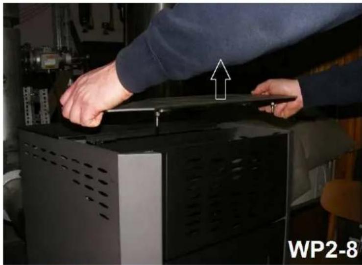
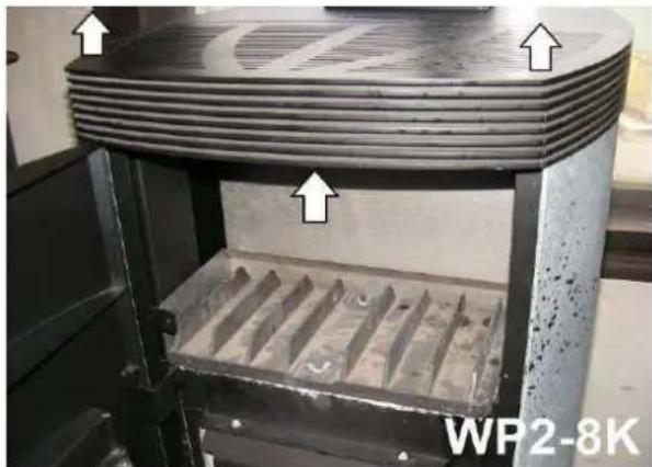
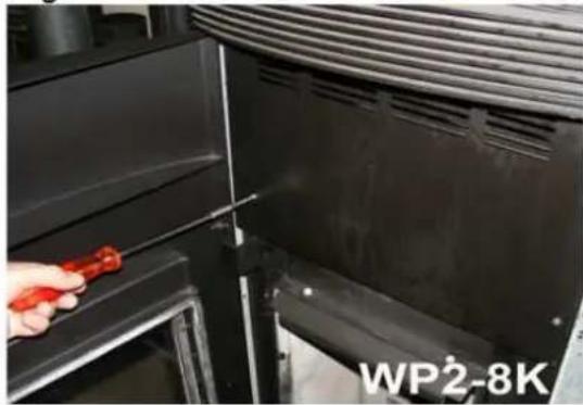
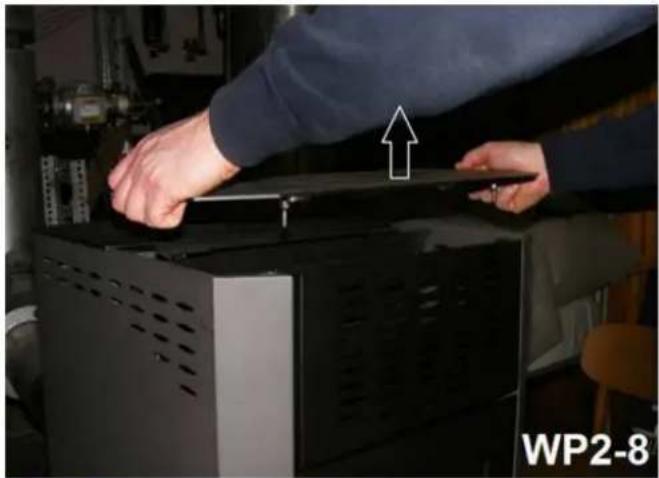
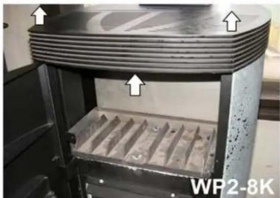
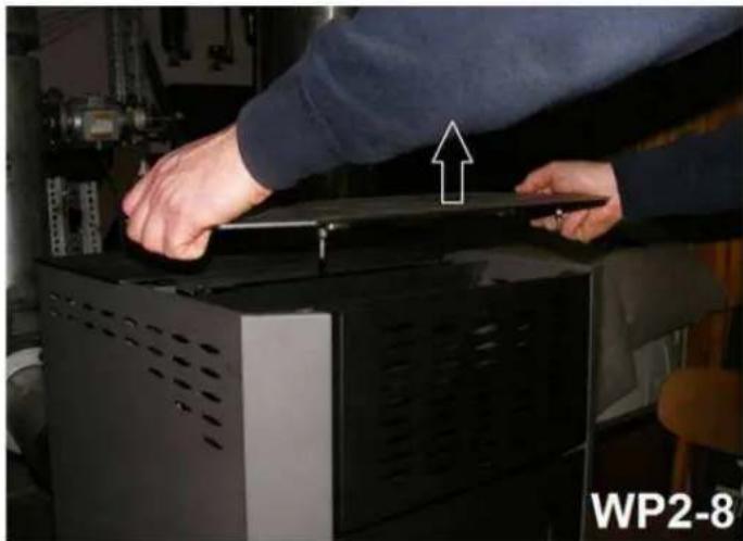
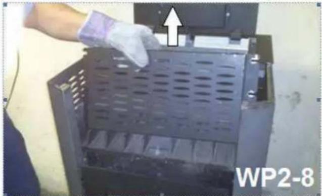
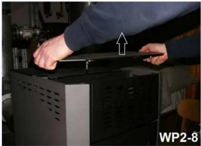
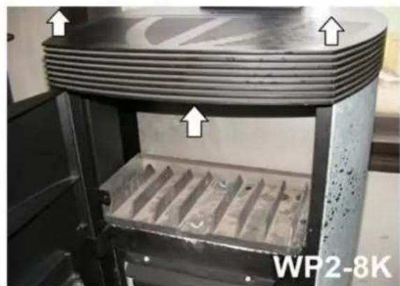
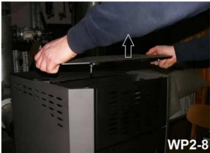
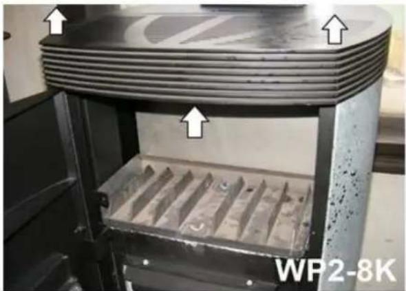
Dismounting the upper cover
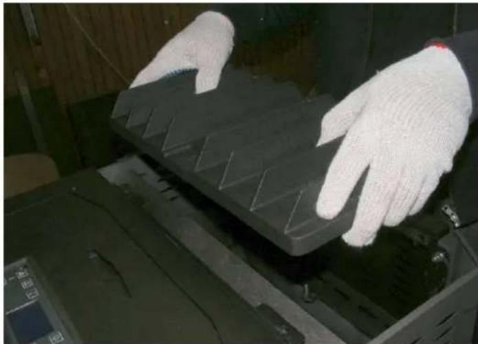
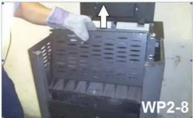
Pull the upper cover upwards with an abrupt motion.
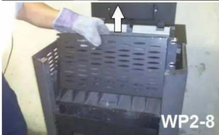
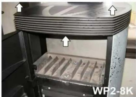
Dismounting the anti-radiation screen
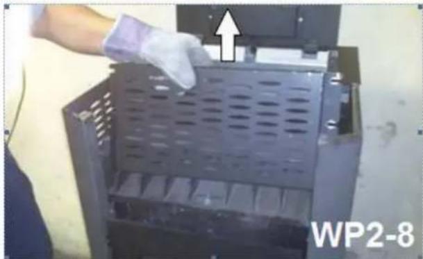
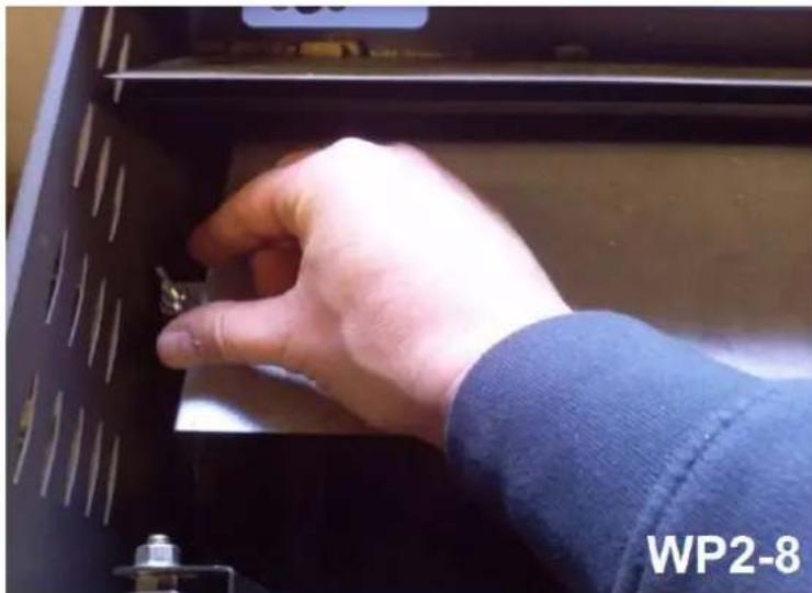
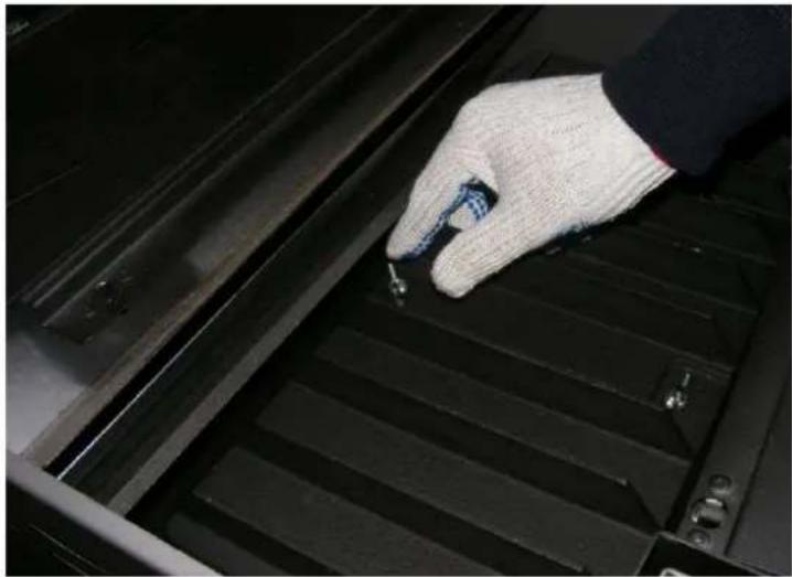
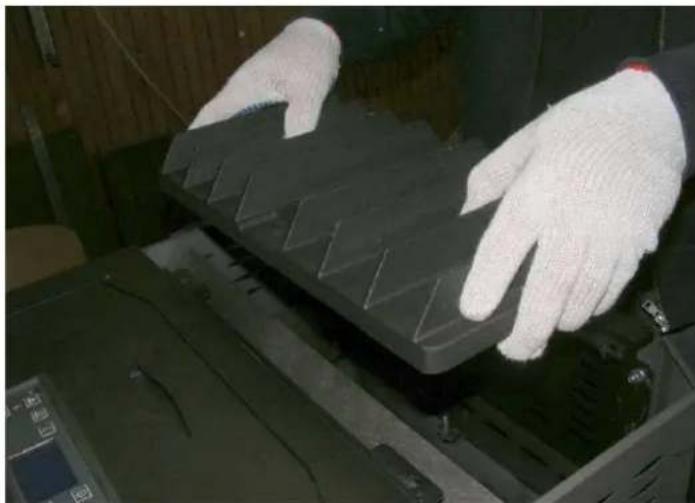
After removing the two butterfly nuts, the stop plate can be lifted out from the boiler body by pulling it upwards at an angle.
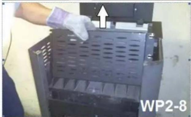
Dismounting the cover of the combustion chamber
After removing the two butterfly nuts, the cover of the combustion chamber can be lifted out from the boiler body by pulling it upwards at an angle.
Warning!
When resetting these elements, pay proper attention to the appropriate tightness of the screws and the undamaged nature of the gaskets!
The lack of adequate tightness may cause malfunctioning!
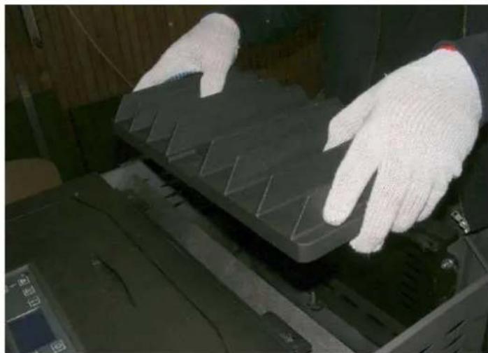
Removal of the guide plate
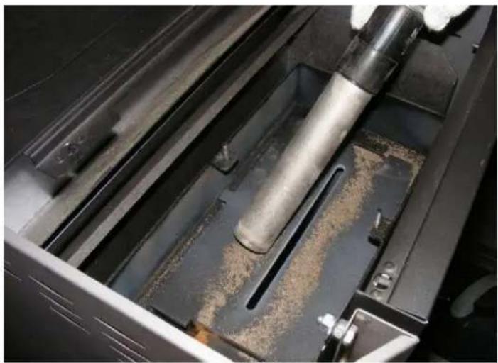
After cleaning the guide plate, the plate can be removed from the boiler body by tilting it upwards at an angle.
Warning!
When resetting these elements, ensure their correct positions, because incorrect resetting may lead to malfunctioning!
| Dismounting the cleaning coverRemove the lower cover section.Then, remove the four screws, and lift the cover.Keep the gaskets undamaged! | 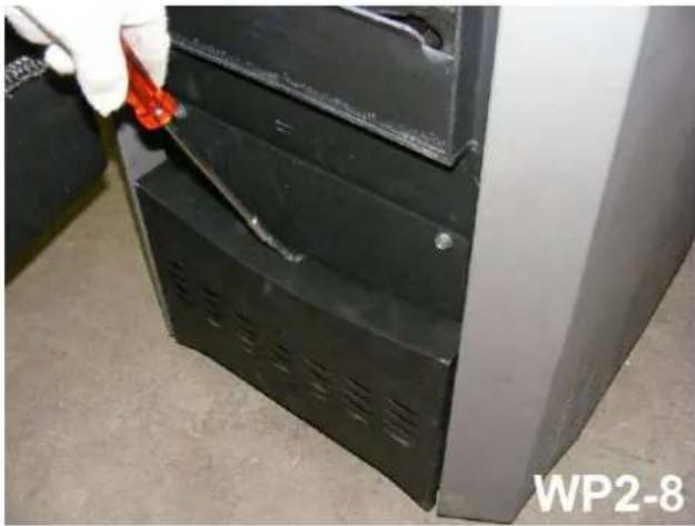 |
| Warning!When resetting these elements, pay proper attention to the appropriate tightness of the screws and the un-damaged nature of the gaskets!The lack of adequate tightness may cause malfunctioning! | 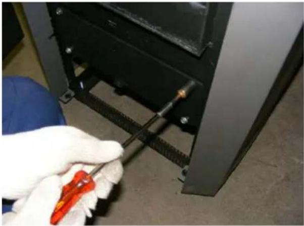 |
| Cleaning the ash compartmentPull out the ash tray after exhausting the ash. | 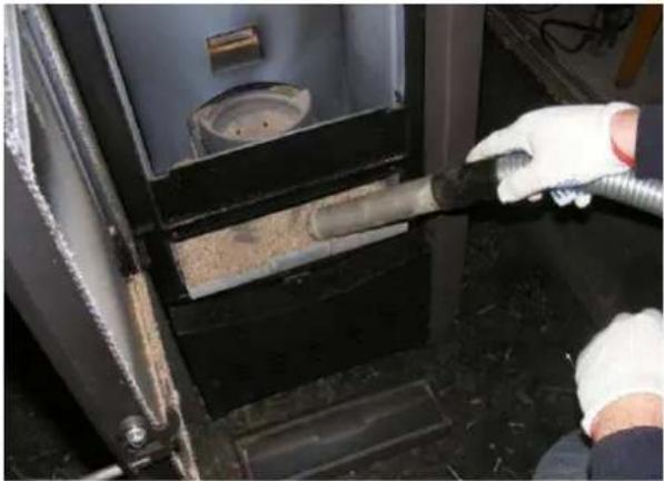 |
| Cleaning the exhaust gas passageThe fan house can be cleaned after re-moving the ash tray. | 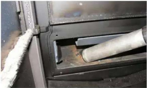 |
Dismounting the heat exchangers
Simply lift the two (right / left) heat ex-changers to remove them from the boiler body.
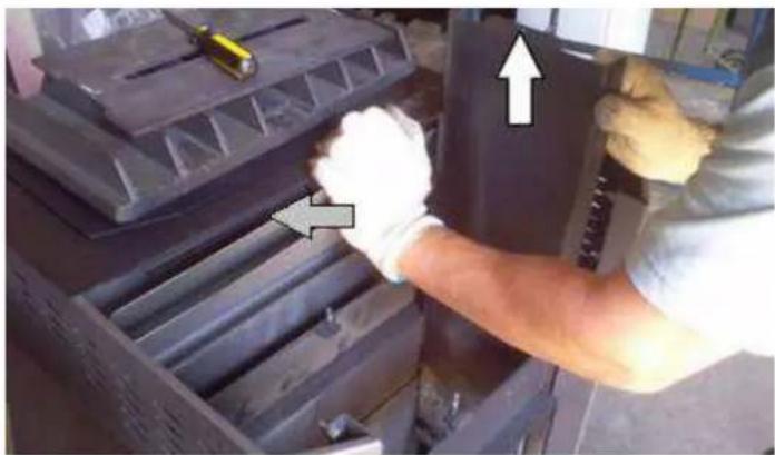
Cleaning the heat exchangers
Vacuum clean the exhaust gas passages of the heat exchangers, and brush any deposits off them.
Watch the bore hole to the right!
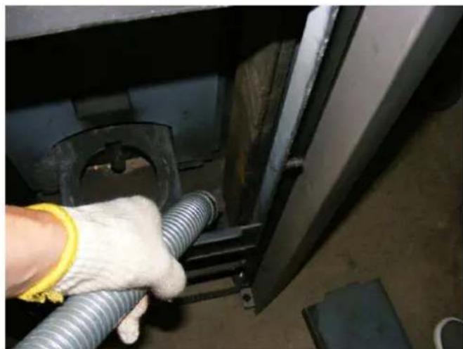
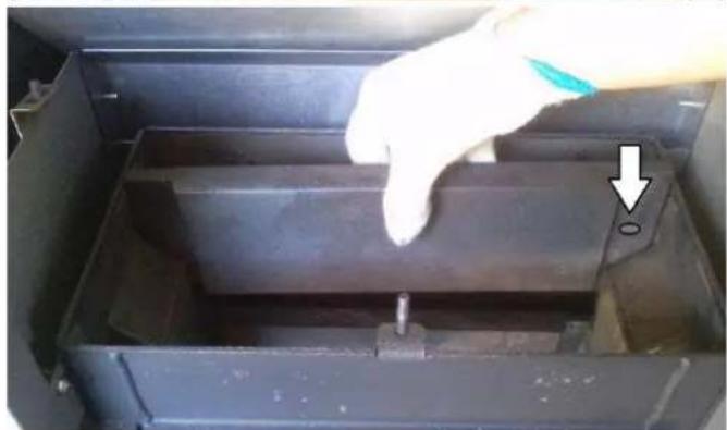
Warning! / Important!
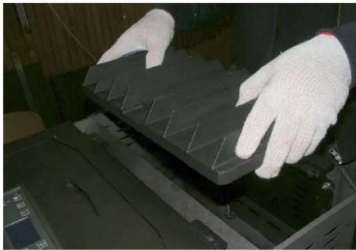
Give the pellet tank a good turnout at least once per year.
The dust could be a reason for the malfunction!
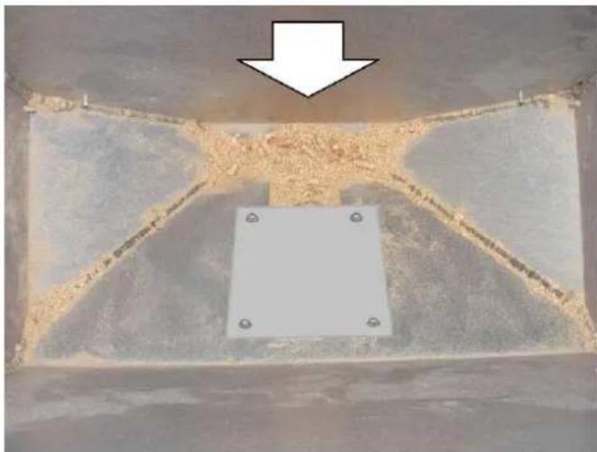
Re-assemble the boiler in a reversed order!
Pay attention to the undamaged nature of the gaskets, and correct assembly!
8.6. CHECKING THE AIR INLET
When an external combustion air line is connected to the boiler, then first inspect this line all along its length to see whether it is clogged. It is suitable for ensuring whether the boiler receives sufficient combustion air. All clogging and deposited materials (for instance, accumulated dust, etc.) have to be fully removed. In combustion air lines, their throats have to be installed at locations places protected against wind pressure outside buildings. No dust, toxic or corrosive gases, steams may be conducted to these lines.
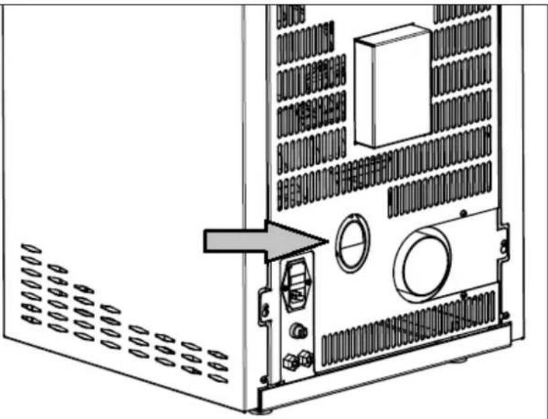
Warning! / Important!
The exhaust gas line connected to the chimney has to be cleaned with the use of a cleaning brush. When this cleaning operation is not performed, the removal of combustion products from the combustion chamber becomes more difficult, which may lead to operation disturbances!
8.7. CHECKING AND CLEANING THE ELECTRICAL PARTS
Again, ensure in advance whether the power supply connector has been unplugged. Check the laying of the electric cables visually. It is forbidden to conduct cables across sharp edges or hot places, while cables cannot have cracks or naked surfaces. Cracked or otherwise damaged cables shall be replaced. When they are strongly dusty, electrical structural elements have to be cleaned with a brush, and corrosion remains shall be removed from the electrical contacts as required.
After the completion of the maintenance works, all the connections shall be inspected, and test operations shall be carried out.
9. FIRE PROTECTION REQUIREMENTS
Near the boiler, all the combustible building parts, furniture or even ornamental objects have to be protected against the effects of heat. The locally valid fire protection provisions and requirements shall be observed at all times.
| Size | Value | Significance |
| A | 100 cm | The smallest distance to the outlet points of hot air in the radiation range. |
| B | 50 cm | The smallest distance to the outlet points of hot air in the radiation range, with ventilated anti-radiation protection. |
| C | 30 cm | Smallest distance beyond the radiation range. |
| D | 20 cm | Smallest flue insulation at the wall passage with insulation (no ventilation). |
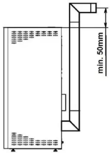
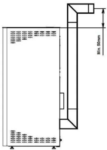
Figures for the interpretation of fire protection distances
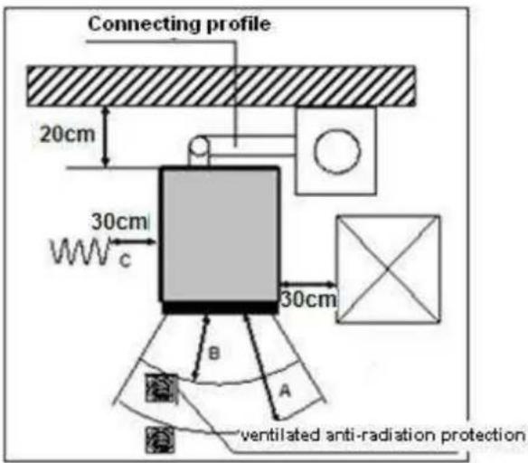
Example with a connecting profile to the chimney, beyond the room of installation
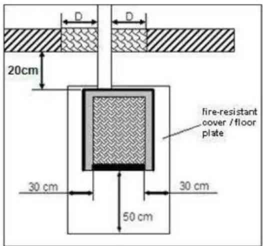
Example with a connecting profile via the wall to the chimney
9.1. FIXTURES IN THE RADIATION RANGE
In the radiation range of the fire, the minimally 100 cm distance (size "A") of combustible building parts, furniture or for instance ornamental elements has to be kept from the front edge of the control window. This safety distance can be reduced to 50 cm (size "B") in case ventilated anti-radiation protection is mounted in front of the building part to be protected.
9.2. FIXTURES BEYOND THE RADIATION RANGE
Near the boiler, all the combustible building parts, furniture and even ornamental objects have to be protected against the effects of heat.
At the side and rear of the boiler, there may not be combustible building materials or such covers in case the distance remains under 30 cm at the side, and 20 cm to the rear. The lateral distance from wooden or plastic furniture parts should also be 30 cm.
9.3. FLOOR UNDER AND IN FRONT OF THE BOILER
Any floor made from flammable materials, such as carpets, parquets or corkwood covering under the boiler and in front of the opening of the fire chamber has to be replaced and protected at least 50 cm ahead and at least 30 cm to the sides (not from the outer edge of the boiler, but from the inner edge of the opening of the fire chamber) with covering of incombustible construction material, for instance ceramics, glass, stone or a steel floor plate.
Load-bearing capacity of the floor
Before installation, ensure that the supporting structure has the load-bearing capacity to sustain the weight of the boiler.
Under the boiler, it is not necessary to have supplementary thermal insulation, only a sufficiently load-bearing and fire-resistant base is enough, as there is no heat dissipation downwards.
9.4. OBJECTS IN THE RANGE OF THE AIR SUPPLY AND AIR CIRCULATING OPENINGS
All the air inlet and outlet openings shall always be perfectly unobstructed, they may not be closed or covered: due to overheating and fire hazards!
9.5. DISTANCES FROM THE CONNECTING PROFILES (FLUE)
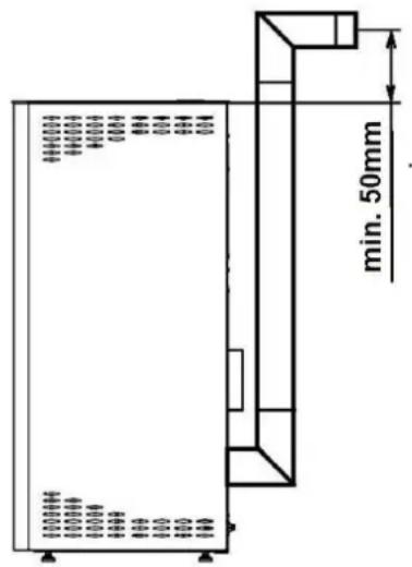
The connecting profiles have to be connected to each other and the boiler in a massive and tights manner. They may not protrude into the unobstructed cross-section of the chimney. The connecting profile between the boiler and chimney shall have the same cross-section as the pipe stub on the boiler. Connecting profiles that are longer than 0.5 meter shall rise above the chimney by 10 degrees. Pipes that are not thermal-insulated or vertically conducted may not be longer than 1.5 meter.
The X size (distance to flammable construction materials / other materials) shall be observed in line with the data specified by the manufacturer of the connecting profile.
9.6. CHIMNEY CONNECTION
The equipment has to be connected to a chimney permitted for solid fuels. The diameter of the chimney shall be at least 120 mm. Excessively long flue gas paths to the chimney have to be avoided. The horizontal length of the exhaust gas line may not be longer than 1.5 meter. Avoid too many changes in the direction of the flow of the exhaust gas going to the chimney. There may be 3 arcs in the exhaust gas line at the maximum. If the exhaust gas line cannot be connected to the chimney directly, preferably use a connecting profile with a cleaning hole. The connecting profiles shall be made from metal, and comply with the standard requirements. (The connections have to be mounted in an air-tight manner). Before installation, the calculations for the chimney need to be performed. Single distribution is subject to the requirements of Standard EN13384-1, whereas multiple distribution is subject to the requirements of Standard EN13384-2. The discharge of flue gases has to be ensured even in times of power outage.
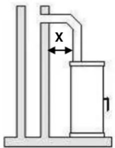
Direct connection
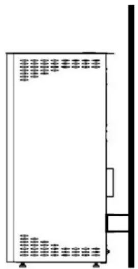
Connection as per the EN review
10. PERMITTED FUELS
According to the Bundesimmissionsschutz-Verordnung (1. BlmSchV) Federal Emission Decree, solely natural wood pellet can be used in this boiler.
The pellet boilers we manufacture can be fuelled only with pellet grades complying with Standard ENplus-A1, DINplus or Ö-Norm M7135. No wood pellet whose ash content is >0.5% can be used, as then the cleaning and maintenance expenditure would be excessive. The requirements associated with the quality of the pellet as described in Section 3.5 shall always be observed.
Never use any shredded wood or other fuels, waste materials. Other fuels may cause harms and loading to the environment. If the boiler is operated with unpermitted fuels, then all the warranty and guarantee demands will become invalid, and hazardous operating conditions may occur. Do not experiment with the fuels! The allowable diameter of the pellet is in the range from 5 to 7 mm. The average length of the pellets should not exceed 30–35 mm. It is similarly forbidden to use pellets of excessive dust content (> 5%).
11. STORAGE OF THE PELLET
Wood pellet is delivered in fully dry conditions, and therefore it can be directly used for burning in the pellet boiler. To preserve the quality of the pellet, the fuel shall be kept dry, free from contaminations.
The pellet cannot be stored in bags outdoors, or exposed to atmospheric effects Its consequence would be the clogging of the screw conveyor.
12. CUSTOMER SERVICES / SPARE PARTS
Your professional dealer will be in charge of customer services, maintenance and the supply of spare parts. He is to serve information, and help you in all issues concerning the WAMSLER Pelletofen pellet boiler.
Should you have any problem with the equipment, or be unable to eliminate operating disturbances, please contact your professional dealer.
When lodging a complaint or ordering spare parts, you are always required to specify the manufacturing number from the data plate of the boiler, as well as the date of purchasing in order to enable the professional dealership to provide you with expertly assistance, and supply the appropriate spare parts.
Your service company, WAMSLER Haus und Küchentechnik GmbH wishes you coziness and warmth, as well as plenty of hours to be spent with your WAMSLER pellet boiler.
Internet: www.wamsler.eu
2. DIMENSIONS, SCHÉMA DU CÂBLAGE

Sicherung - fusible
DISPLAY OFF (DESACTIVER L'ECRAN)
1.1. ARRIVÉE À LA VALEUR TEMPERATURE
2. STAND-BY (DÉSACTIVATION)
7.2 RÉACTIVATION DU RÉDUCTEUR DE TEMPÉRATURE DE SÉCURITÉ (STB)
Attention! / Important!
Danger d'incendie, danger de court circuit, danger de vie!
Attention! Danger de feu!
Attention! / Important!
Attention! / Important!
WP2-8A
WP2-8KA (GRAN PELLET)
DISPLAY OFF (DISATTIVAZIONE DELLO SCHERMO)
5.1. ARRIVO AL VALORE DELLA TEMPERATURA
6. STAND-BY
7.2. RIACCENSIONE DEL RIDUTTORE DI TEMPERATURA DI SICUREZZA(STB)
Connect the two wires of the thermostat into the designated M10 connector to terminal 3, 4.
8.2. PULIZIA DELLA FINESTRA DI CONTROLLO
10. COMBUSTIBILI AUTORIZZATI
WP2-8
WP2-8K (GRAN PELLET)
2.20. HIBA RIASZTÁSOK
2.23. BIZTONSÁGI HÖMÉRSÉKLET KORLÁTOZÓ (STB) VISSZAKAPCSOLÁSA
WP2-8 HU 184 / 192
Figyelem!
WP2-8 HU 186 / 192
Fontos útmutatás!

- WICHTIGER HINWEIS
- ACHTUNG / WICHTIG
- TABLE OF CONTENTS
- IMPORTANT GENERAL INSTRUCTIONS
- SYSTEM REQUIREMENTS
- MINIMUM OPERATING TIMES / APPLICATION OF EXTERNAL REGULATORS
- CONNECTION TO CHIMNEYS
- SUPPLY OF THE COMBUSTION AIR
- QUALITY OF THE PELLET
- CLEANING, MAINTENANCE AND CARE
- ELECTRIC POWER SUPPLY
- THE APPLIANCE AND THE DESCRIPTION OF ITS OPERATION
- TECHNICAL SPECIFICATIONS
- IMPORTANT NOTE
- SCOPE OF SUPPLY
- DESCRIPTION OF THE OPERATION
- CROSS-SECTION OF OPERATION
- FIRST COMMISSIONING
- IMPORTANT INSTRUCTIONS
- FILLING THE SUPPLY TANK
- PROCEDURE TO SWITCH THE APPLIANCE ON
- OUR RECOMMENDATION
- BEFORE STARTUP / IGNITION
- OPERATING AND HEATING MODE
- SETTING THE CONTRAST OF THE SCREEN
- ILLUMINATION OF THE SCREEN
- CHANGING THE TEMPERATURE
- ACCESS TO THE CHRONO – THERMOSTAT MENU
- OPEN THE INFORMATION PERTAINING TO THE BOILER
- TEMPERATURE MENU
- USER MENU
- GENERAL SETTINGS
- SETTINGS MAIN MENU
- DATE / PRECISE TIME
- DISPLAY OFF
- STANDBY
- FERNBEDINUNG (J/N) / REMOTE CONTROL (YES/NO)
- SPRACHWAHL / LANGUAGE SELECTION
- START
- INITIAL CLEANING CONDITIONS
- HEATING CONDITIONS
- FULL LOADING CONDITION
- STAND-BY CONDITION
- CONDITION OF SWITCHING ON
- STABILIZATION CONDITION
- OPERATING CONDITION
- OPERATION
- REACHING THE TEMPERATURE (TEMPERATUR) VALUE
- SETTING THE TEMPERATURE
- SETTING THE TIMER
- SELECTION OF THE FUNCTIONS AND HOUR RANGES
- MODIFICATION OF THE DAYS OF THE WEEK
- COPYING THE SETTINGS OF THE DAY OF THE WEEK
- EXAMPLE ACCORDING TO THE FIGURE
- DISABLING THE AUTOMATED MODE
- ADJUSTMENT OF THE PERFORMANCE GRADE
- DISCHARGING/CHARGING THE PELLET TANK
- WARNING
- IMPORTANT INSTRUCTION
- ENABLING / DISABLING THE "BEEP" AUDIO SIGNAL
- STAND-BY (SWITCHING OFF)
- BOILER SWITCHES OFF
- INACTIVE STATUSES
- COOLING DOWN
- POWER OUTAGE
- PRESSURE DROP (PNEUMATIC STORAGE TANK)
- ALARM
- ACKNOWLEDGMENT OF THE ALARM
- FUSE REPLACEMENT
- WARNING! THE FUSE MAY BE REPLACED ONLY BY QUALIFIED PERSONNEL
- RESETTING OF THE SAFETY TEMPERATURE LIMITER (STB)
- CONNECTION OF THE EXTERNAL ROOM THERMOSTAT
- ENABLING THE EXTERNAL THERMOSTAT IN THE EXTERNAL SOFTWARE
- CLEANING AND CARE
- WARNING! / CAUTION
- WARNING! / IMPORTANT
- INSPECTING AND CLEANING THE BURNER PAN
- REMARK
- CAUTION! FIRE HAZARD
- CLEANING THE BURNER PAN HOLDER
- CLEANING THE INSPECTION WINDOW
- CLEANING THE SURFACES
- MAINTENANCE
- CLEANING THE HOT GAS PASSAGES
- DISMOUNTING THE UPPER COVER
- DISMOUNTING THE ANTI-RADIATION SCREEN
- DISMOUNTING THE COVER OF THE COMBUSTION CHAMBER
- REMOVAL OF THE GUIDE PLATE
- DISMOUNTING THE HEAT EXCHANGERS
- CLEANING THE HEAT EXCHANGERS
- CHECKING THE AIR INLET
- CHECKING AND CLEANING THE ELECTRICAL PARTS
- FIRE PROTECTION REQUIREMENTS
- FIXTURES IN THE RADIATION RANGE
- FIXTURES BEYOND THE RADIATION RANGE
- FLOOR UNDER AND IN FRONT OF THE BOILER
- LOAD-BEARING CAPACITY OF THE FLOOR
- OBJECTS IN THE RANGE OF THE AIR SUPPLY AND AIR CIRCULATING OPENINGS
- DISTANCES FROM THE CONNECTING PROFILES (FLUE)
- CHIMNEY CONNECTION
- PERMITTED FUELS
- STORAGE OF THE PELLET
- CUSTOMER SERVICES / SPARE PARTS
- DIMENSIONS, SCHÉMA DU CÂBLAGE
- DISPLAY OFF (DESACTIVER L'ECRAN)
- ARRIVÉE À LA VALEUR TEMPERATURE
- STAND-BY (DÉSACTIVATION)
- 7.2 RÉACTIVATION DU RÉDUCTEUR DE TEMPÉRATURE DE SÉCURITÉ (STB)
- ATTENTION! / IMPORTANT
- ATTENTION! DANGER DE FEU
- DISPLAY OFF (DISATTIVAZIONE DELLO SCHERMO)
- ARRIVO AL VALORE DELLA TEMPERATURA
- STAND-BY
- RIACCENSIONE DEL RIDUTTORE DI TEMPERATURA DI SICUREZZA(STB)
- PULIZIA DELLA FINESTRA DI CONTROLLO
- COMBUSTIBILI AUTORIZZATI
- HIBA RIASZTÁSOK
- BIZTONSÁGI HÖMÉRSÉKLET KORLÁTOZÓ (STB) VISSZAKAPCSOLÁSA
- FIGYELEM
- FONTOS ÚTMUTATÁS
Brand : Wamsler
Model : WP 2-8
Category : Pellet boiler