
W2-50 - Wood stove Wamsler - Free user manual and instructions
Find the device manual for free W2-50 Wamsler in PDF.


User questions about W2-50 Wamsler
0 question about this device. Answer the ones you know or ask your own.
Ask a new question about this device
Download the instructions for your Wood stove in PDF format for free! Find your manual W2-50 - Wamsler and take your electronic device back in hand. On this page are published all the documents necessary for the use of your device. W2-50 by Wamsler.
USER MANUAL W2-50 Wamsler
natural_image
White industrial stove with visible flame inside, no text or symbols presentW2-50
Vorwort
1. Installation ....4
text_image
Technical diagram of a 13-pin washing machine with numbered components for identificationLegende
text_image
Exploded view diagram of a refrigerator with numbered parts for identification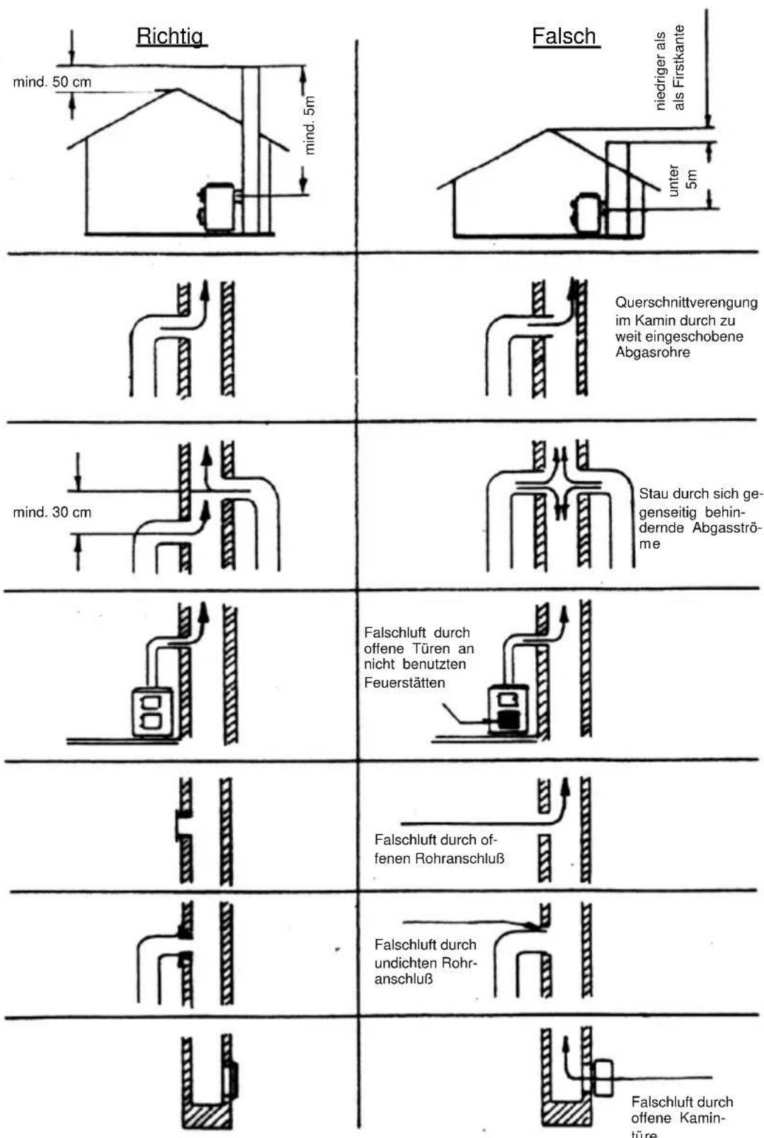
natural_image
Three circular diagrams with concentric rings and a vertical stripe, labeled 1 and 2 (no text or symbols beyond labels)1 - Scheitholz
2 - Braunkohle
3.1.3 Anheizklappe
text_image
Exploded view diagram of a laboratory oven with labeled components including tray, casing, and door assemblynatural_image
Technical line drawing of a mechanical component with no visible text or symbolsBild 5
text_image
2. 3.natural_image
Technical line drawing of a two-tiered industrial vessel or enclosure with circular components and a dimension label (167) — no readable text or symbols beyond the dimension marker.Congratulations on your purchase of our solid fuel stove. You have made a good choice. Because this product guarantees you:
• High Quality by using proved materials with top quality.
- Safe function thanks to mature technology which has been tested for strict adherence to German and European standards.
- Long durability thanks to a sturdy construction.
This solid fuel stove provides you with a contemporary compact unit to provide your
- Cooking
- Heating
These stoves save energy, are environmentally friendly and really simple to use. You will find everything you need to know as well as some useful hints in this manual.
Please note that the stove must only be installed by a qualified professional, who will also be available to help you should you have any problems at a later date.
PLEASE NOTE:
When ordering replacement parts, the Article No. and Serial No. shown on the identification plate must be quoted.
Please see the heading "Fuel / Settings" for instructions on the maximum quantity of fuel and details of the maximum chimney draught (15 Pa).
If you put in too much fuel and/or the draught from the chimney is too strong, there is a risk of overheating, which can damage the stove and/or the oven thermometer. The oven thermometer goes up to a temperature of 350^ C max. The stove can only be used when the fuel door (fire door) is shut.
This door must only be opened when lighting, topping up fuel or cleaning the fire box.
Any damage to the stove or the thermometer which has obviously been caused by overheating is not covered by the guarantee.
Table of Contents
Preface 23
Table of Contents.... 24
1. Installation 25
1.1 Safety measures 25
1.2 Parts.... 27
1.3 Instructions.... 28
1.4 Surrounding space....28
1.5 Air supply 28
1.6 Safe distances.... 30
1.7 Chimney attachment ....31
1.8 Choice of flue gas connection placement 31
1.8.1 Top connection (Fig. 1)....31
1.8.2 Side connection (Fig. 1)....32
2. Fuels / Settings.... 34
2.1 Fuels 34
2.2 Combustion airflow settings 35
3. Use.... 35
3.1 Controls for use and settings 35
3.1.1 Performance Regulator ....35
3.1.2 Secondary air control / Air - logic 35
3.1.3 Start damper.... 36
3.1.4 Ash pan.... 36
3.1.5 Implement drawer.... 36
3.2 Lighting.... 37
3.3 Cooking and heating ....37
3.4 Closing down.... 38
3.5 Notes on heating.... 38
3.6 Care and cleaning.... 38
3.6.1 Cooker (Fig. 4)....38
3.6.2 Varnished and enamel surfaces.... 39
3.6.3 Ceramic glass surfaces 39
3.6.4 Sheet steel....39
3.6.5 Side panel top....40
3.7 Troubleshooting 41
4. Technical data 42
4.1 Data.... 42
4.2 Dimensions 42
1. Installation
1.1 Safety measures
- The stoves are tested to DIN EN 12815 (see identification plate).
- For installation and for flue gas connections, the requirements of the Fire Regulations (FeuVO in Germany) apply, as well as local building regulations such as the following technical standards DIN 4705, DIN EN 13384, DIN 18160, DIN EN 1856-2 and DIN EN 15287. In order for the stove to function correctly the chimney to which you want to connect the stove must be in good condition.
- Before first use and before connecting to the chimney, you must read the Instructions for Use carefully and inform the local authority responsible for approving heating systems.
- While installing the stove you are recommended to wear clean cotton gloves, in order to avoid leaving fingerprints which can be difficult to remove afterwards.
- In the interests both of clean air, and of the safe functioning of the stove, the fuel quantities listed in the Instructions for Use should never be exceeded, and the doors of the stove must be shut during use to avoid the risk of overheating, which can lead to damage to the stove. Damage due to this cause is not covered by the guarantee.
- The stove doors must remain shut at all times while the stove is in use.
-
Permitted fuels are:
-
Natural chopped firewood (up to 35 cm max. in length)
-
Lignite (brown coal) briquettes (see permitted fuels in the Instructions for Use)
-
Never use liquid fire starters. Use either special firelighters or wood shavings.
- Burning rubbish, fine chips, bark, coal slack, chips from planing, damp wood or wood treated with preservative, paper, cardboard or similar is not permitted.
- The first time the stove is heated there may be some smoke and an unpleasant smell. Make sure that the room is well ventilated (open windows and doors) and heat for at least an hour at the maximum nominal heat load. If the maximum temperature is not reached the first time the stove is heated, then there may be further unpleasant smells at a later date.
- All controls and settings must be used as indicated in the Instructions for Use. When the stove is hot, please handle only using the implements or protective gloves provided.
- If the stove is not working correctly, or if the chimney is not drawing properly, smoke may appear when the fire door is opened. It is very important to only open the fire door slowly, initially just a crack, then wait a few seconds before opening fully. In addition, before opening the fire door to top up the fuel, make sure that only glowing material is present: there must not be any visible flames.
- Do not place any flammable items in the warming drawer or on the surface of the stove.
- When in use, all surfaces and particularly the glass doors and handles and other controls can become very hot. Make children, young people, older people and animals aware of this danger, and keep them away from this source of heat when
the stove is being used. Use the protective gloves or the implements provided.
Children and young people under 16 must not use the stove unless supervised by an adult who is responsible for them.
- Make sure that the ash pan is always fully pushed in, until it touches the back. Never remove ashes while still hot (fire risk).
- In spring and autumn the chimney may no longer draw correctly, so that gases produced by combustion are not completely removed. The fire chamber should then be filled with a small quantity of fuel, ideally with wood shavings, and lit under supervision, in order to stabilise the chimney draught. The grate must be clean.
- After each prolonged period of use for heating, have the stove checked by a professional. The flues and pipes for the evacuation of fumes must also be thoroughly cleaned.
- If repairs or replacements are necessary, please contact your supplier with the necessary article numbers and serial numbers in good time. Only original WAMSLER replacement parts may be used.
- Work such as installation, setup, commissioning and services, as well as repairs, must only be carried out by qualified personnel (heating system or space heating technicians). Intervention by non-qualified persons invalidates the warranty and guarantee.
- As the solid fuel oven/stove draws the air required for combustion from the surrounding room, you must ensure that sufficient air can be drawn in through non-sealed windows and outside doors. It can be assumed that is this is provided by a room volume of at least 4 m^3 per kW nominal heat capacity. If the volume is less than this, then air vents can be used to provide access to further air in other rooms (min. 150 cm^2 ).
- You must ensure that the correct safety distance is maintained from all flammable components and materials – to the side, rear and front. These distances can be found in the Instructions for Use or the identification plate.
- The fire chamber must not be modified.
- Connection to a chimney whose functional height is less than 4 m, or if multiple stoves are installed, 5 m, is not permitted. A maximum of two other fires can be connected to the chimney which is to be connected the stove.
- If the chimney catches fire immediately close all doors and openings and call the fire brigade. Do not attempt to extinguish the fire yourself. Afterwards have the chimney thoroughly checked out by a professional.
- Solid fuels naturally create soot, so it is always possible that the window glass will become dirty: this does not mean there is a malfunction.
1.2 Parts
W2-50
text_image
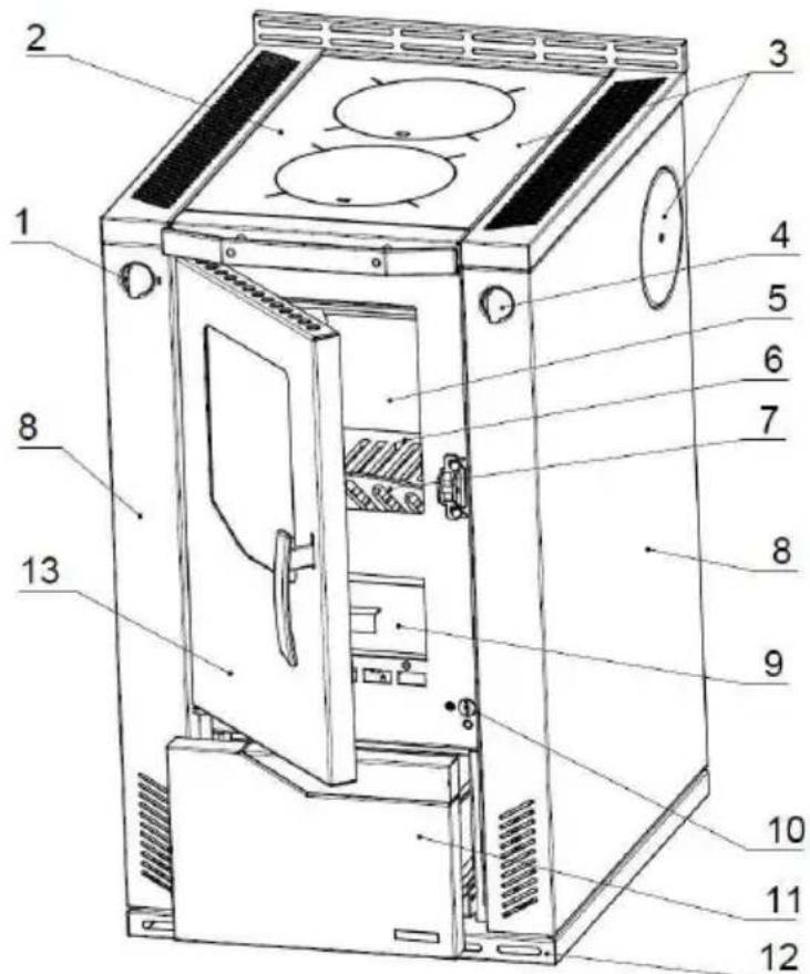
Technical diagram of a 13-pin electrical oven with numbered components for identificationKey: Standard accessories:
-
Primary air control - Flue cover
-
Steel plate - Protective gloves
-
Flue gas connections - Lever to lift covers
-
Start damper - Soot scraper
-
Refractory clay layer in fire chamber - Fire iron
-
Grate
-
Wood guard (Railing)
-
Side
-
Ash pan Special accessories:
-
Secondary air control - ISO Panel
-
Fuel trolley
-
Base
-
Fire door
- Suction knob for ceramic glass (Hot Spots)
- flue gas connection top
1.3 Instructions
For installation and for connection of flue, the requirements of the Fire Regulations (FeuVO in Germany) apply, as well as local building regulations such as the following technical standards DIN 4705, DIN EN 13384, DIN 18160, DIN EN 1856-2 and DIN EN 15287. In order for the stove to function correctly the chimney to which you want to connect the stove must be in good condition.
1.4 Surrounding space
The stove draws the air required for burning from the surrounding room. You must ensure that sufficient air can be drawn in through non-sealed windows and outside doors. In addition you must ensure that a room volume/heat capacity ratio of at least 4 m^3 per kW nominal heat capacity is available. If the volume is less than this, then air vents can be used to provide access to further air supply in other rooms (connecting vents min. 150 cm^2 ).
1.5 Air supply
A constant supply of oxygen or air is required for the combustion process. Normally the air available in the room where the stove is installed will be sufficient.
If the windows and doors are well insulated, if mechanical air extraction mechanisms are present (e.g. in a kitchen or bathroom) or if there are other sources of fire (including gas boilers) in the home, then the supply of available air can be significantly impacted. If this is the case, the option exists to draw in air for burning directly from outdoors or from another, well-ventilated room (e.g. a cellar).
The stoves provide a built-in air supply opening in the base, ∅ 80 mm.
For the air supply you must use only smooth pipes with a minimum diameter of 80 mm. A shutoff valve must be placed in the air supply close to the stove, which must be installed professionally, at the bends there must be inspection openings for the local authority responsible for approving heating systems and it must be professionally sealed against condensation. The pipe must not be longer than 4 m and must not have more than 3 bends. If the pipe exits out-of-doors, then it must have appropriate wind protection and be covered by a mesh.
NOTE: In the room where the stove is installed or in the neighbouring rooms there must not be any air extractors or similar equipment. These could cause considerable operating problems and even represent a risk. Consult the local authority responsible for approving heating systems.
NOTE: The room where the stove is to be installed must not have equipment such as extractor hoods, ventilation systems etc. which could mean that that room or neighbouring rooms have reduced air pressure.
Important NOTES relevant to operation dependent on air supply from room or independent of air supply from room (valid for Germany – as of January 2013):
- The stoves have been tested under DIN EN 12815 as stoves relying on air supply from room. The stoves take in all the air required for combustion via the central air intake from the surrounding room. This intake can have an external enclosed air supply attached to it. Even with this sealed air supply the stoves do not meet the requirements for operation independent of the air supply from the room.
- If used in combination with air management systems (e.g. controlled air supply and evacuation systems, steam extractors or similar) then in Germany Part 4 of Fire Regulations (FeuVO) apply. These determine among other things, that the stove and the air management systems must be jointly managed (e.g. using a differential pressure monitor) or an air supply system must be installed, which is approved for use with solid fuel stoves and which supplies the room where it is installed with sufficient additional air (approx. 20 ~m^3 / h ) for the combustion in the fire box.
- You must always comply – in consultation with the local authority responsible for approving heating systems – with the local rules and regulations. We cannot accept any responsibility for changes subsequent to the publication of this instruction manual. We reserve the right to make changes.
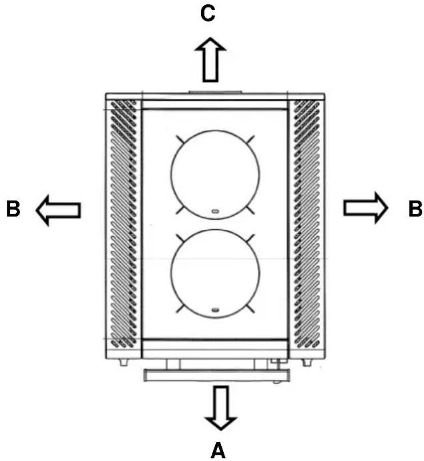
1.6 Safe distances
The following distances must be respected as safety margins from flammable objects and bearing walls made of reinforced concrete and partition walls made from flammable materials or covered in flammable materials:
Beneath the hob plate (from the top of the stove to the floor)
$$ A \geq 8 0 0 m m $$
$$ B \geq 3 m m ^ {*} $$
$$ C \geq 2 0 0 m m $$
Above the hob plate (radiation area of the hob plate)
$$ A \geq 8 0 0 \mathrm{mm} $$
The silicon dividers which are supplied must be fitted to the side panel to ensure this.
Any flammable items attached above the stove must be kept at a suitable distance. The minimum distance is 800 mm.
Floor in front of the stove
Floors made of flammable substances, such as e.g. carpets, parquet, laminate, plastics or cork, must be replaced or covered by a non-flammable substance e.g. ceramic, stone, glass or a steel floor-plate for a distance of 500 mm forwards and 300 mm sideways.
The connection piece must not pass between flammable building materials or furniture. If connected at the side, the safety gap required by the manufacturer between it and any flammable materials must be respected.
text_image
C B ← A B1.7 Chimney attachment
The connection for attaching to the chimney must be able to withstand at least 400^ C.
PLEASE NOTE:
Before connecting the stove the local authority responsible for approving heating systems must be consulted!
Connection pieces must be firmly connected to the stove and to each other and must not leak. They must not project into the open diameter of the chimney.
The connection piece between the stove and the chimney must have the same diameter as the pipe socket on the stove. Horizontal connection pieces of over 0.5 m must rise towards the chimney at an angle of 10 degrees. Any pipes
which are not heat insulated or vertical must not be longer than 1 metre.
The requirements of the Fire Regulations (FeuVO) apply, as well as local building regulations such as for the chimney standards DIN 4705, DIN EN 13384, DIN 18160 and DIN EN 15287.
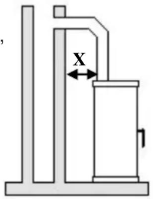
Connection pieces must be tested to DIN EN 1856-2. Measurement X (distance from flammable construction and other materials) must be as defined by the manufacturer of the connection piece.
PLEASE NOTE:
text_image
XFitting to a chimney with a functional height of less than 4 m, or if several stoves are being fitted, less than 5 m, is not permitted. (See: Data for chimney calculations / Chapter 4.) A maximum of two other fires can be connected to the chimney to be connected to the stove.
For safety reasons it is not permitted to use a steam extractor hood to remove air when the stove is producing heat.
1.8 Choice of flue gas connection placement
The flue outlet is attached to the back of the stove as standard. If a connection to the side or the top is required, then the unused connection must be closed off.
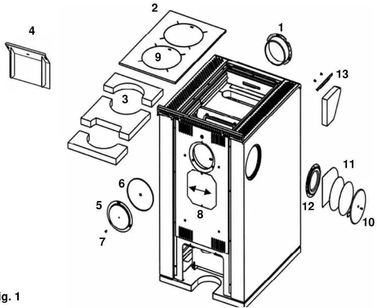
1.8.1 Top connection (Fig. 1)
- Remove the rear flue adapter (1) by loosening the screws.
- Remove cooking plate (2) and fire bricks (3)
- Remove steel plate (4) in the exhaust
- Close flue gas connection at the back from outside using the blank cover supplied (5) and screw this tight.
- Bolt tight the cover (6) at the inside with the outside cover (7)
- Swing back cover (8) upwards and close
- Remove flue gas cover (3) and the large hob plate (2)
- Connect the optional flue connection set (9) from below to the opening and screw tight at the cooking plate.
- Replace the steel plate (4), the fire bricks (3) and the cooking plate (2)
1.8.2 Side connection (Fig. 1)
- Remove the rear flue outlet (1) by loosening the screws.
- Remove the cooking plate (2) and the fire bricks (3)
- Remove the steel plate (4) in the exhaust
- Bolt tight the cover (6) at the inside with the outside cover (7).
- Swing back cover (8) upwards and close
- Remove the side cover plate (10) by loosening the screws.
- With a Stanley cut and remove the 3 holders of the insulation plate (11)
- Loosen the screws in the side blank cover (12) and remove cover
- Fasten flue outlet adapter (1) to the side panel and screw tight
- Remove fire bricks from inside by taking of the screws
- Replace the steel plate (4), the fire bricks (39 and the cooking plate (2))
The connection piece must not be fed through flammable construction materials or furniture elements. When using a side connection, the safety distance from flammable elements required by the manufacturer of the connection must be respected.
text_image
g. 1 1 2 3 4 5 6 7 8 9 10 11 12 13Fig. 1
text_image
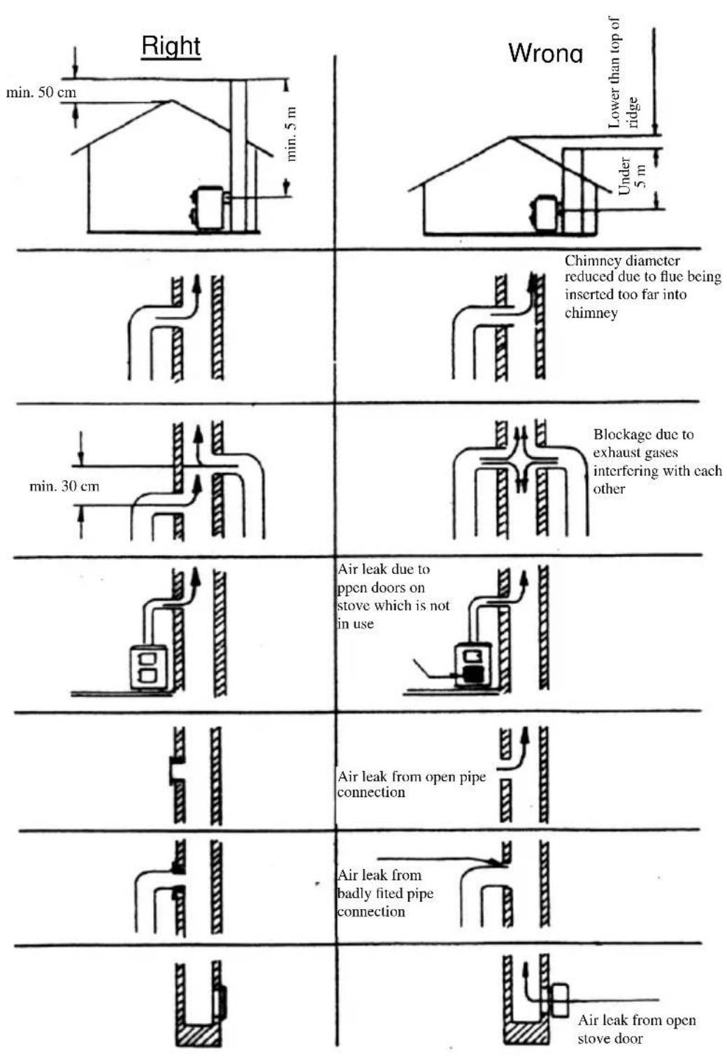
Right min. 50 cm min. 5 m Wrona Lower than top of ridge Under 5 m Chimney diameter reduced due to flue being inserted too far into chimney min. 30 cm Blockage due to exhaust gases interfering with each other Air leak due to open doors on stove which is not in use Air leak from open pipe connection Air leak from badly fitted pipe connection Air leak from open stove doorAction in case of chimney fire!
If a chimney is not cleaned often enough, or if the wrong type of fuel is used (e.g. damp wood) or the air flow is maladjusted the chimney may catch fire. In this case close the air supply to the fire chamber and call the fire brigade.
Never try to extinguish it yourself using water!
2. Fuels / Settings
2.1 Fuels
Low smoke, trouble-free operation of the stove and a supply of heat at the nominal level with a chimney draught of 12 Pa are only guaranteed when you use the following fuels and no others.
Only use natural, dry chopped firewood with a remaining humidity of max. 20% and lignite (brown coal) briquettes.
| Type of fuel Heating value appr. k | Wh/kg |
| Lignite briquettes | 5,3 – 5,5 |
| Hardwood | 4,0 – 4,2 |
| Softwood | 4,3 – 4,5 |
Non-permitted fuels include:
Rubbish, fine chips, pellets, bark, chips from planing, coal slack, damp wood or wood treated with preservative, paper, cardboard or similar. For lighting use wood shavings or barbecue lighters. Never use liquid fire starters!
PLEASE NOTE:
The first time the stove is heated there may be some smoke and an unpleasant smell. Make sure that the room is well ventilated (open windows and doors) and heat for at least an hour at the maximum nominal heat load. If the maximum temperature is not reached the first time the stove is heated, then there may be further unpleasant smells at a later date.
Maximum fuel quantities per load
| W2-50 | |
| Lignite briquettes | 3.1 kg (5 - 6 briquettes) at nominal heat load3.1 kg (5 - 6 briquettes) for long term load(other settings, see Table 2) |
| Firewood 2.0 kg (1 - 2 logs) | |
Table 1
2.2 Combustion airflow settings
The settings must always be as shown.
| Fuel | Primary airflow setting | Start damper setting | Secondary airflow setting | Combustion duration in hrs | |
| Lighting |  3 3 |  2 2 |  | - | |
| Firewood | Nominal heat load | 2 |  |  | approx. 1 |
| Lignite briquettes | Nominal heat load | 3 |  |  | approx. 2 |
| Lignite briquettes | Long-term heating |  |  |  | approx. 12 |
| Not in use: do not add any more fuel | [GZ7K] |  | [BAG5] | - | |
Table 2
3. Use
3.1 Controls for use and settings
3.1.1 Performance Regulator
text_image
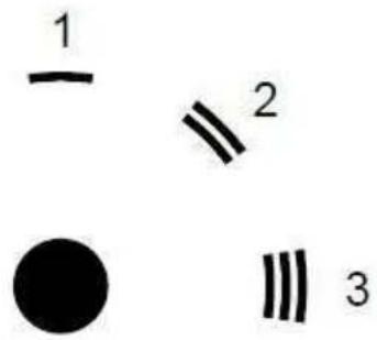
1 2 ● 3The rate of combustion and therefore the heat delivered by the stove are determined by the amount of air for combustion air flowing under the grid. This primary air supply is set using the performance regulator control.
1 - Closed
2 - Firewood
3 - Lignite
3.1.2 Secondary air control / Air - logic
natural_image
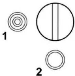
Three abstract geometric shapes: concentric circles, a vertical line within a circle, and a hollow circle, with no text or symbols.The secondary air regulator is on the inside of the frame, behind the fire door. Choose the setting for the fuel.
1 - Firewood
2 - Lignite
3.1.3 Start damper

For lighting the stove the start damper must be open and when cooking or heating it must be closed.

1 - Closed (cooking, heating)
2 - Open
PLEASE NOTE:
Leaving the start damper open when heating will cause the stove to overheat which will damage the stove and its parts. In addition leaving the start damper open will increase fuel consumption.
3.1.4 Ash pan
- The ash pan is underneath the combustion chamber. It must be checked and emptied regularly.
- Emptying the ash pan must be done when the stove is cold. Please ensure that no glowing or burning pieces of wood are remaining. Please make sure that no glowing, unburned residues end up in the dust bin.
- Always remember to put the ash pan back in its place. Forgetting to do this makes use of the stove dangerous.
- You must ensure that the ash pan is pushed in until it touches the rear wall.
3.1.5 Implement drawer
This storage drawer is at the base of the stove and is large enough to hold the various implements needed during use of the stove. The maximum load it can hold is 10 kg. Heavier items can cause damage to the storage drawer. The implement drawer is opened by pressing lightly on the middle of the drawer. Never pull on it when it is closed!
PLEASE NOTE:
It is absolutely forbidden to store easily flammable materials in this drawer, such as alcohol, petrol, liquid fuels, paints or varnishes, lighters, paper etc.
3.2 Lighting
The performance control is set depending on the type of fuel as a function of the chimney draught and the desired heating level. With firewood and particularly with softwood, only a limited heating period is possible. Lignite briquettes are much better suited to burning overnight, if they are placed on top of a layer of glowing embers.
Heating / using for the first time
- Before using make sure any fixings for transport are removed from the deflection plate over the fire chamber and remove any stickers on the glass window, making sure no traces remain.
Open the fire door by lifting the catch. When the stove is hot use a protective glove. Set the primary and secondary air settings as shown in Table 2 "Combustion air flow settings". Open the start damper. Place a starter briquette or some wood shavings on the grid. Then add some smaller, then larger pieces of wood light it and shut the fire chamber door. Once the fire is burning strongly and there is a sufficient base of embers, add more fuel and shut the start damper off. The first time the stove is lit it should be done "gently", with a small amount of fuel, to allow the stove parts to get used to the heat. The first time the stove is heated there may be some smoke and an unpleasant smell. Make sure that the room is well ventilated (open windows and doors) and heat for at least an hour at the maximum nominal heat load. If the maximum temperature is not reached the first time the stove is heated, then there may be further unpleasant smells at a later date. Never throw pieces of fuel into the fire chamber, but place them, as otherwise the lining may be damaged.
The loading door (fire door) must always be kept shut when the stove is in use. It may only be opened when lighting, filling up or cleaning the fire chamber.
PLEASE NOTE:
If not working correctly, or if the chimney is not drawing properly, smoke may appear when the fire door is opened. It is very important to only open the fire door slowly, initially just a crack, then wait a few seconds before opening fully. In addition, before opening the fire door to top up the fuel, make sure that only glowing material is present: there must not be any visible flames.
3.3 Cooking and heating
Whenever the stove is being used for cooking or heating the start damper must be kept shut.
For optimum cooking on the hob plate you are recommended to use pans with a flat base. The hottest area is in the centre of the plate, so this is the best area to use to heat up a pan quickly. The edges of the plate can be used to keep food warm. To get a faster heating up time (to boiling point) we recommend using thinly chopped softwood.
The hob plate must not be overheated as this will damage the stove but not help in any way with cooking.
3.4 Closing down
Close the primary air regulator (Table 2).
Let the embers burn out and leave the stove to cool down.
Once the stove is cold, empty and clean out the fire chamber and ash pan!
3.5 Notes on heating
A properly adjusted secondary air flow ensures that any combustible elements in the flue gases are burned off. This means they are burned in a way which reduces the smoke and soot released into the environment. it is always possible that the window glass will become dirty and this does not mean there is a malfunction.
If you use your stove in the spring or autumn, you must check the draw of your chimney first, as if the outside temperatures are high this can drop off substantially. To do this hold a burning match in the fire door when it is partially opened. If the flame is not clearly drawn inwards, then you first need to light a starter fire. Do this by briefly burning some wood shavings in the stove or the cleaning opening of the chimney itself.
The grid must be cleaned before placing any fuel on it, in order to ensure a good supply of air to the burning material. The ash pan must be emptied regularly, when it is cold. If the stove is still hot, use the gloves provided. Please make sure that no glowing embers are put into your dustbin.
Take care that the ash pan is pushed in until it touches the rear wall.
PLEASE NOTE:
In the interests of clean air and safe functioning of the stove do not exceed the maximum quantities of fuel. Otherwise there is a risk of overheating, which can damage the stove. Damage of this kind is not covered by the guarantee. Reduced heating should only be achieved by reducing the quantity of fuel, never by reducing the primary airflow.
3.6 Care and cleaning
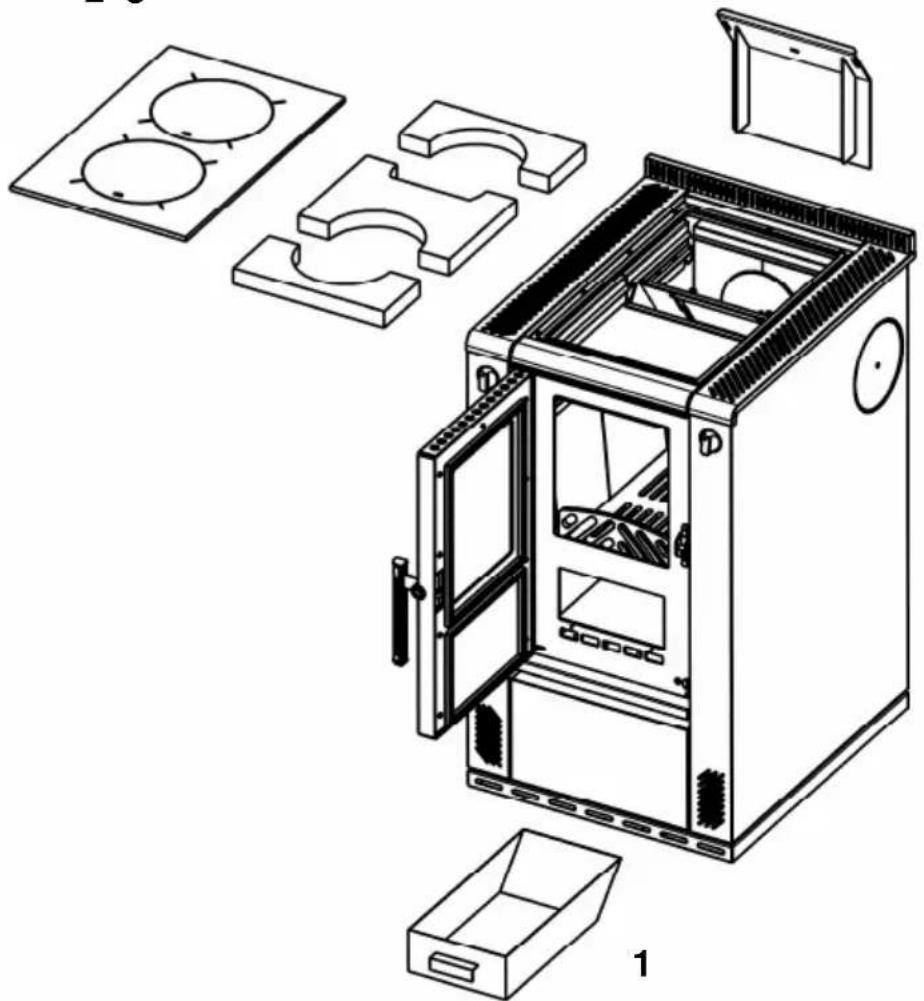
3.6.1 Cooker (Fig. 4)
After opening the fire door the grid must be cleaned using the soot scraper and the fire iron before adding fuel.
The ash pan (1) should be emptied daily. The grid should be scraped clean of cinders at least every third day.
By using/managing and caring for/cleaning your stove properly you enhance its value and prolong its useful life. You save valuable resources and spare both the environment and your wallet. The hob plates (2) and heating plates (3) should be removed for cleaning and cleaned free from soot. By removing the hob and heating plates the flue gas channel and the flue pipe inside the stove can also be
cleaned. By loosening of the cleaning cover (4) the lower part of the flue gas channel around the oven can also be cleaned.
After finishing cleaning, the heating and hob plates must be replaced correctly.
The cleaning cover (4) under the oven needs to be closed tightly again.
PLEASE NOTE:
After every period of heating you should check the stove thoroughly. If repairs or replacements are necessary, please contact your supplier with the necessary article numbers and serial number in good time.
3.6.2 Varnished and enamel surfaces
Only wipe down the external surfaces when the stove is cold. Varnished surfaces should only be washed with plain water (do not scrub). Enamel surfaces in special cases can be cleaned with soapsuds or a bit of washing-up liquid and then wiped dry.
NOTE: Never use sponges, scouring products or any other chemical or abrasive cleaning products!
3.6.3 Ceramic glass surfaces
Clean the window and/or Ceran plate before first use with a clean damp cloth.
Then rub a few drops of a ceramic glass protection product onto the glass / Ceran plate with a paper towel.
After wiping this and polishing it dry, the high quality surface is now covered with an invisible film. The helps to keep the glass pane /Ceran plate clean and if repeated regularly, makes it easy to clean.
3.6.4 Sheet steel
The steel sheet parts must be rubbed over with an acid-free sheet steel care product when at blood temperature. Cleaning is then done when the stove is cold.
The special steel plates which radiate heat need to be taken care of regularly after each time you cook. After any use which causes dampness or dirt to collect on the plate, you must clean it. The hob plate should be cleaned when it is still lukewarm, which allows any remaining water to evaporate and so prevents rust forming. Take care that you do not use water to clean the stove when it is cold.
Expansion joints in the steel hob plate must always be cleaned free of adhesions, to avoid deforming the steel hob plate and the side panels. If necessary the edge of the cover should also be cleaned of any adhesions.
Work such as installation, setup, commissioning and servicing, as well as repairs, must only be carried out by qualified personnel (heating system or space heating technicians). Intervention by non-qualified persons invalidates the warranty and guarantee.
Parts explosion diagram for Chapter 3.6 Care and cleaning:
2 3
4
natural_image
Exploded view diagram of a mechanical oven with internal compartments and housing (no text or labels)Fig. 4
3.6.5 Side panel top
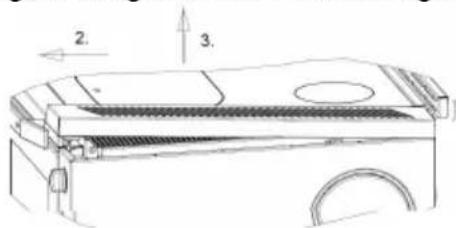
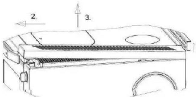
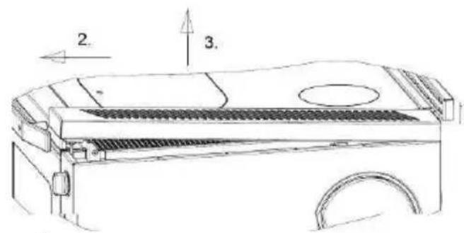
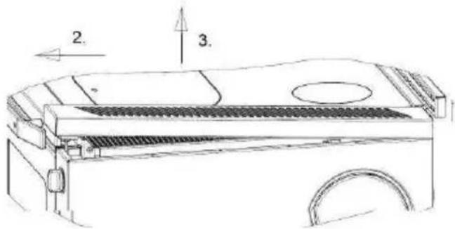
- Stainless steel grating, lifting (Figure 5)
- Pull forward
- and lifting
After disassembling the stainless steel grating, can the underlying hole tray, be cleaned.
Reassembly takes place in reverse order.

natural_image
Technical line drawing of a mechanical device with no visible text or symbolsFig. 5
text_image
2. 3.3.7 Troubleshooting
Your stove has been built using modern technology.
Even so, problems can arise, which may derive from the chimney, the fuel or the flue pipe system. There may briefly be smoke and an unpleasant smell the first time you use the stove: this is normal. Make sure the room is sufficiently well ventilated.
| PROBLEM CAUSE SOLUTION | ||
| Pane of glass in the fire chamber is covered in soot and/or the fire chamber is dirty and black from smoke | Not enough chimney draught< 10 PaToo high chimney draught (temporarily max. 18 Pa allowed) | Check whether the connection piece is blocked |
| Change the connection: more draught with a suitable throttle damper or improve the insulation | ||
| Wrong settings See the section on “Use” and “Fuel” | ||
| Too much fuel Reduce the fuel quantity | ||
| Fuel with too high relative humidity | Let damp wood dry out before burning | |
| Unsuitable fuel Look up section on “Fuels” | ||
| Chimney draught not suitable or chimney dirty | Chimney sweep No regular draught | |
| Dirt inside stove or pipes Cleaning | ||
| Emission of too much black smoke | Lighting/Running the stove with wood which is too green | Use better quality wood which has been stored to dry |
| Flue channel partly blocked | Call a qualified technician | |
| Smoke coming out of stove | Fire chamber door is open Shut the door | |
| Not enough draught Get the chimney inspected by local heating authority | ||
| Incorrect settings | Look up sections “Use” and “Fuel”. | |
| Dirt in stove | Clean stove and the pieces connecting to the chimney | |
Table 3
4. Technical data
4.1 Data
| Model number W2 - 50 | |
| Nominal heat load 6 kW | |
| Space heating ability in m^3 in favourable / less favourable / unfavourable conditions according to DIN 18893/TABLE. 2Short-term heatingLong-term heating | 114 / 68 / 46165 / 95 / 65 |
| Exhaust gas for fuel:Exhaust gas massExhaust gas connector temperatureFlow pressure at nominal heat loadParticles / dust (based on 13% O2)CO ( based on 13% O2)Efficiency | Firewood / Lignite9,7 / 9,7 g/s275°C12 Pa≤ 40 mg/ m^3 ≤ 0,09 %≥ 77 % |
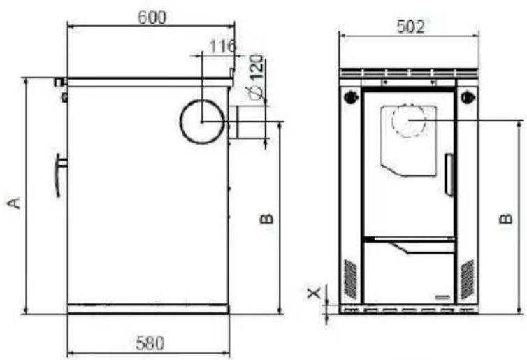
4.2 Dimensions
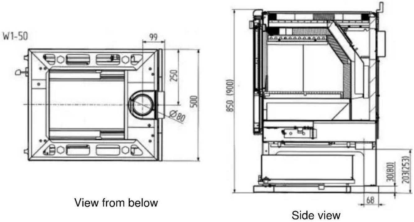
W2-50
text_image
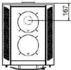
600 116 Ø120 A B 580 502 B X| X A B | |||
| 30 | 850 (+20) | 695 (+20) | |
| 80 | 900 (+20) | 745 (+20) | |
natural_image
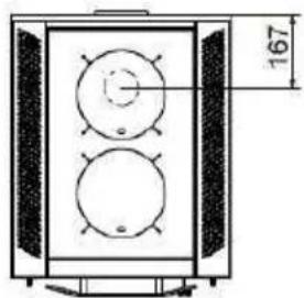
Technical line drawing of a two-cylinder electrical enclosure with a 167-unit height dimension标注 (no text or symbols on the diagram itself)screw feet
can raise stove height by +20 mm
The dimension information shown is only for information! We reserve the right to make changes to the construction if these improve the technical level or the quality!
Innovation from Tradition
We reserve the right to make changes which relate to technical advances and / or to an improvement in quality. We accept no liability for printing errors and changes which occur after printing.
Préface
FR
Cher client,
3.7 Causes de perturbations, solutions....63
text_image
Technical diagram of a 13-pin washing machine with numbered components for identificationtext_image
Exploded view diagram of a refrigerator with numbered parts for identificationnatural_image
Three circular diagrams with concentric rings and a vertical line, labeled 1 and 2 (no text or symbols beyond labels)natural_image
Technical line drawing of a mechanical device with a circular opening and a curved base (no text or symbols)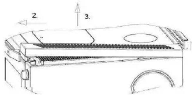
text_image
2. 3.Fig 5.
3.7 Causes de perturbations, solutions
natural_image
Technical line drawing of a two-tiered industrial vessel or enclosure with circular components and a dimension label (167) on the right side.text_image
Technical diagram of a 13-pin washing machine with numbered components for identificationtext_image
Exploded view diagram of a refrigerator with numbered parts for identification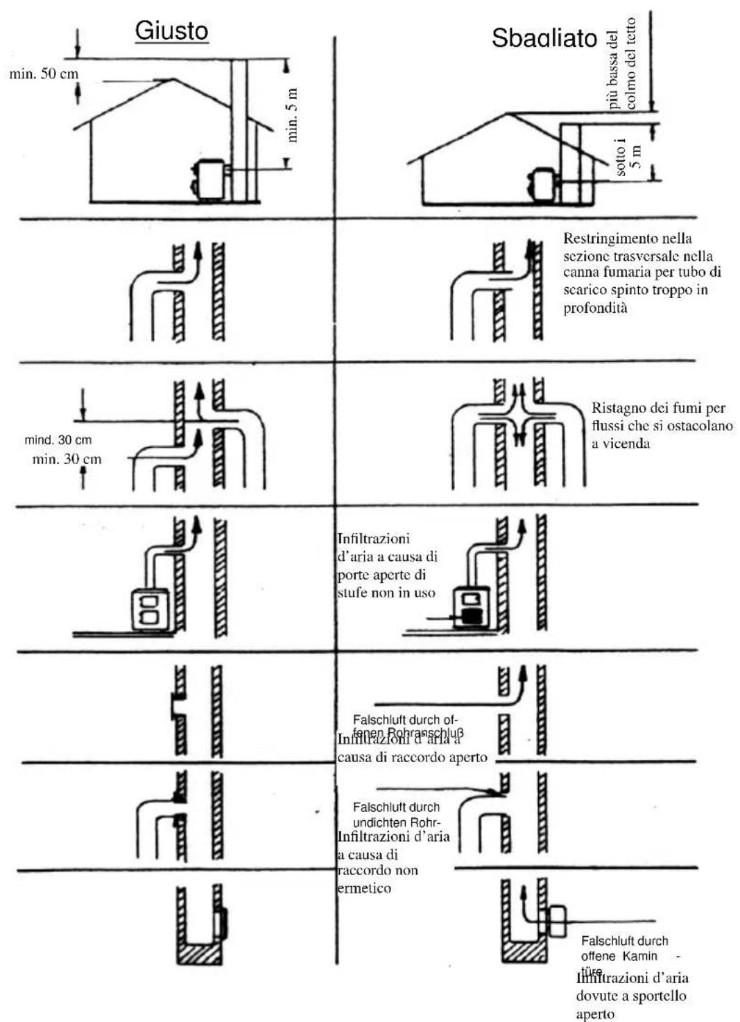
natural_image
Three abstract geometric shapes: concentric circles, a vertical line within a circle, and a hollow circle, with no text or symbols.text_image
Exploded view diagram of a 3D oven with labeled parts including door, tray, and drawer3.6.5 Decorativo laterale
natural_image
Technical line drawing of a mechanical device with no visible text or symbolsFigura 5
text_image
2. 3.text_image
male 600 116 Ø120 A B 580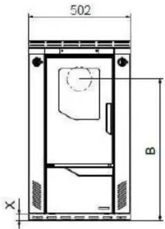
text_image
502 B X| X A B | |||
| 30 | 850 (+20) | 695 (+20) | |
| 80 | 900 (+20) | 745 (+20) | |
natural_image
Technical line drawing of a mechanical device with circular components and a dimension label (167) — no readable text or symbols beyond the dimension marker.text_image
Technical diagram of a 13-pin washing machine with numbered components for identificationMagyarázat
text_image
Exploded view diagram of a refrigerator with numbered parts for identification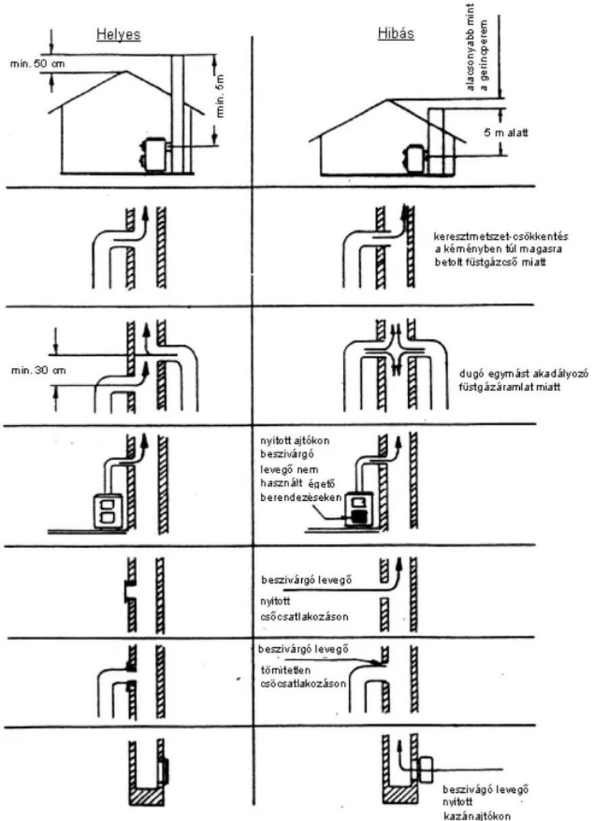
natural_image
Technical line drawing of a mechanical device with no visible text or symbols- kép
text_image
Technical diagram of a vehicle or machine component with numbered parts and directional indicatorstext_image
Technical diagram of an open oven with labeled parts including doors, compartments, and a tray- kép