TRAT30SSV - Basket FABER - Free user manual and instructions
Find the device manual for free TRAT30SSV FABER in PDF.

| Product Type | Built-in Cooktop Hood |
| Brand | Faber |
| Model | TRAT30SSV |
| Width | 76.2 cm (30 in) |
| Estimated Depth | 50 cm |
| Adjustable Height | Yes, with telescopic chimney |
| Estimated Weight | 15 kg |
| Power Supply | 120 V, 60 Hz, 15 A, dedicated circuit |
| Motor Power | Not specified |
| Noise Level | Not specified |
| Number of Speeds | 4 (low, medium, high, intensive) |
| Lighting | LED, replacement by authorized service |
| Grease Filter Type | Metallic, dishwasher safe |
| Charcoal Filter | Optional (ref. FILTER2), replacement every 4 months |
| Controls | Push buttons, delayed shut-off (15 min) |
| Special Functions | Intensive speed (10 min), optional remote control |
| Installation Type | Ceiling mount, ducted or recirculating |
| Duct Diameter | 15.2 cm (6 in) circular, metal |
| Included Accessories | Telescopic chimney, damper, junction box, drilling template |
| Optional Accessories | Non-ducted kit (DUCT2), remote control (REMCTRL2), high ceiling kit (HIGH2) |
| Warranty | 1 year (parts and labor) |
| Certifications | UL, C-UL |
| Maintenance | Grease filters every 2 months; charcoal filter every 4 months |
| Safety | Automatic shut-off after 10 min in intensive speed |
Frequently Asked Questions - TRAT30SSV FABER
User questions about TRAT30SSV FABER
0 question about this device. Answer the ones you know or ask your own.
Ask a new question about this device
Download the instructions for your Basket in PDF format for free! Find your manual TRAT30SSV - FABER and take your electronic device back in hand. On this page are published all the documents necessary for the use of your device. TRAT30SSV by FABER.
USER MANUAL TRAT30SSV FABER
natural_image
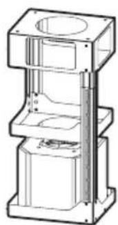
Isometric line drawing of a three-tiered pedestal or column structure with mounting base (no text or symbols)TRATTO IS 36"
Installation Instructions Use and Care Information
READ AND SAVE THESE INSTRUCTIONS BEFORE YOU START INSTALLING THIS RANGEHOOD
WARNING: - TO REDUCE THE RISK OF A RANGE TOP GREASE FIRE:
a) Never leave surface units unattended at high settings. Boilovers cause smoking and greasy spillovers that may ignite. Heat oils slowly on low or medium setting.
b) Always turn hood ON when cooking at high heat or when flambeing food (i.e. Crepes Suzette, Cherries Jubilee, Peppercorn Beef Flambé).
c) Clean ventilating fans frequently. Grease should not be allowed to accumulate on fan or filter.
d) Use proper pan size. Always use cookware appropriate for the size of the surface element.
WARNING: - TO REDUCE THE RISK OF INJURY TO PERSONS IN THE EVENT OF A RANGE TOP GREASE FIRE, OBSERVE THE FOLLOWING*:
a) SMOTHER FLAMES with a close-fitting lid, cookie sheet, or metal tray, then turn off the burner. BE CAREFUL TO PREVENT BURNS. If the flames do not go out immediately EVACUATE AND CALL THE FIRE DEPARTMENT.
b) NEVER PICK UP A FLAMING PAN - You may be burned.
c) DO NOT USE WATER, including wet dishcloths or towels - a violent steam explosion will result.
d) Use an extinguisher ONLY if:
1. You know you have a Class ABC extinguisher, and you already know how to operate it.
2. The fire is small and contained in the area where it started.
3. The fire department is being called.
4. You can fight the fire with your back to an exit.
* Based on "Kitchen Firesafety Tips" published by NFPA
WARNING - TO REDUCE THE RISK OF FIRE OR ELECTRIC SHOCK, do not use this fan with any solid-state speed control device.
WARNING - TO REDUCE THE RISK OF FIRE, ELECTRICAL SHOCK, OR INJURY TO PERSONS, OBSERVE THE FOLLOWING:
- Use this unit only in the manner intended by the manufacturer. If you have any questions, contact the manufacturer.
- Before servicing or cleaning unit, switch power off at service panel and lock the service disconnecting means to prevent power from being switched on accidentally. When the service disconnecting means cannot be locked, securely fasten a prominent warning device, such as a tag, to the service panel.
CAUTION: For General Ventilating Use Only. Do Not Use To Exhaust Hazardous or Explosive Materials and Vapors.
WARNING - TO REDUCE THE RISK OF FIRE, ELECTRICAL SHOCK, OR INJURY TO PERSONS, OBSERVE THE FOLLOWING:
- Installation Work And Electrical Wiring Must Be Done By Qualified Person(s) In Accordance With All Applicable Codes And Standards, Including Fire-Rated Construction.
-
Sufficient air is needed for proper combustion and exhausting of gases through the flue (chimney) of fuel burning equipment to prevent backdrafting. Follow the heating equipment manufacturer's guideline and safety standards such as those published by the National Fire Protection Association (NFPA), and the American Society for Heating, Refrigeration and Air Conditioning Engineers (ASHRAE), and the local code authorities.
-
When cutting or drilling into wall or ceiling, do not damage electrical wiring and other hidden utilities.
- Ducted fans must always be vented to the outdoors.
ALL WALL AND FLOOR OPENINGS WHERE THE RANGEHOOD IS INSTALLED MUST BE SEALED.
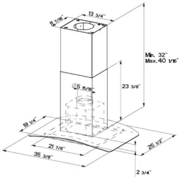
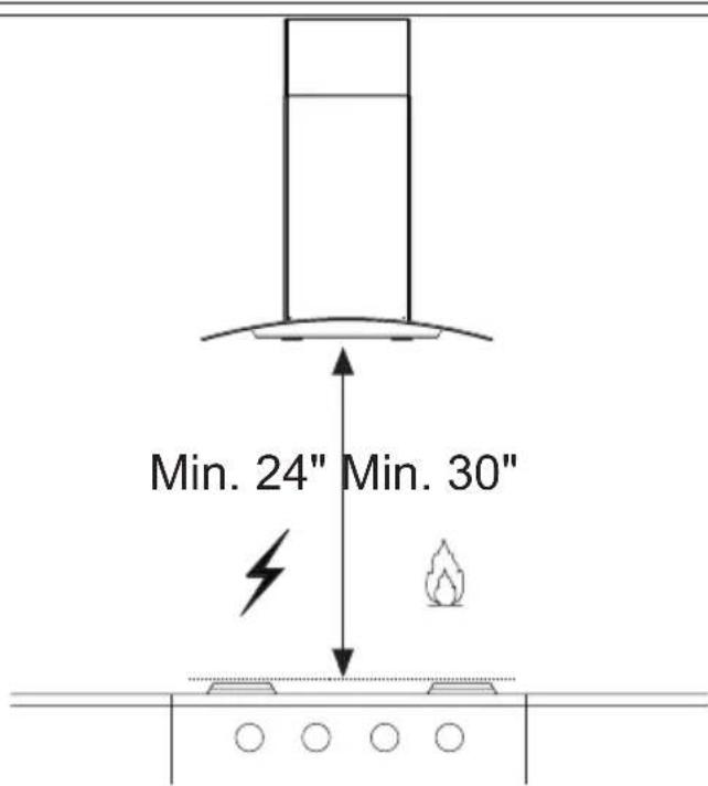
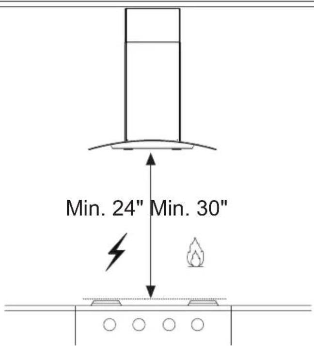
This rangehood requires at least 24" of clearance between the bottom of the rangehood and the cooking surface or countertop. This hood has been approved by UL at this distance from the cooktop.
This minimum clearance may be higher depending on local building codes. For gas cooktops and combination ranges, a minimum of 30" is recommended and may be required.
Overhead cabinets on both sides of this unit must be a minimum of 18" above the cooking surface or countertop. Consult the cooktop or range installation instructions given by the manufacturer before making any cutouts.
MOBILE HOME INSTALLATION The installation of this rangehood must conform to the Manufactured Home Construction and Safety Standards, Title 24 CFR, Part 3280 (formerly Federal Standard for Mobile Home Construction and Safety, Title 24, HUD, Part 280). See Electrical Requirements.
VENTING REQUIREMENTS
Determine which venting method is best for your application. Ductwork can extend either through the wall or the roof.
The length of the ductwork and the number of elbows should be kept to a minimum to provide efficient performance. The size of the ductwork should be uniform. Do not install two elbows together. Use duct tape to seal all joints in the ductwork system. Use caulking to seal exterior wall or floor opening around the cap.
Flexible ductwork is not recommended. Flexible ductwork creates back pressure and air turbulence that greatly reduces performance.
Make sure there is proper clearance within the wall or floor for exhaust duct before making cutouts. Do not cut a joist or stud unless absolutely necessary. If a joist or stud must be cut, then a supporting frame must be constructed.
WARNING - To Reduce The Risk Of Fire, Use Only Metal Ductwork.
CAUTION - To reduce risk of fire and to properly exhaust air, be sure to duct air outside – Do not vent exhaust air into spaces within walls or ceilings or into attics, crawl spaces, or garages.

WARNING
- Venting system MUST terminate outside the home.
- DO NOT terminate the ductwork in an attic or other enclosed space.
- DO NOT use 4" laundry-type wall caps.
- Flexible-type ductwork is not recommended.
- DO NOT obstruct the flow of combustion and ventilation air.
- Failure to follow venting requirements may result in a fire.
ELECTRICAL REQUIREMENTS
A 120 volt, 60 Hz AC-only electrical supply is required on a separate 15 amp fused circuit. A time-delay fuse or circuit breaker is recommended. The fuse must be sized per local codes in accordance with the electrical rating of this unit as specified on the serial/rating plate located inside the unit near the field wiring compartment.
ELECTRICAL INSTALLATION WITH WIRING BOX
THIS UNIT MUST BE CONNECTED WITH COPPER WIRE ONLY. Wire sizes must conform to the requirements of the National Electrical Code, ANSI/NFPA 70 - latest edition, and all local codes and ordinances. Wire size and connections must conform with the rating of the appliance. Copies of the standard listed above may be obtained from:
National Fire Protection Association
Batterymarch Park
Quincy, Massachusetts 02269
This appliance should be connected directly to the fused disconnect (or circuit breaker) through flexible, armored or nonmetallic sheathed copper cable. Allow some slack in the cable so the appliance can be moved if servicing is ever necessary. A UL Listed, 1/2" conduit connector must be provided at each end of the power supply cable (at the appliance and at the junction box).
When making the electrical connection, cut a 1 1/4" hole in the wall. A hole cut through wood must be sanded until smooth. A hole through metal must have a grommet.

WARNING
- Electrical ground is required on this rangehood.
- If cold water pipe is interrupted by plastic, nonmetallic gaskets or other materials, DO NOT use for grounding.
• DO NOT ground to a gas pipe. - DO NOT have a fuse in the neutral or grounding circuit. A fuse in the neutral or grounding circuit could result in electrical shock.
- Check with a qualified electrician if you are in doubt as to whether the rangehood is properly grounded.
- Failure to follow electrical requirements may result in a fire.
State of California Proposition 65 Warning (US only)
WARNING
This product contains chemicals known to the State of California to cause cancer and birth defects or other reproductive harm.
For more information go to www.P65Warnings.ca.gov
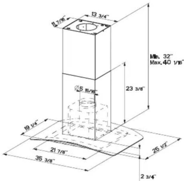
RANGEHOOD DIMENSIONS
MAIN PARTS
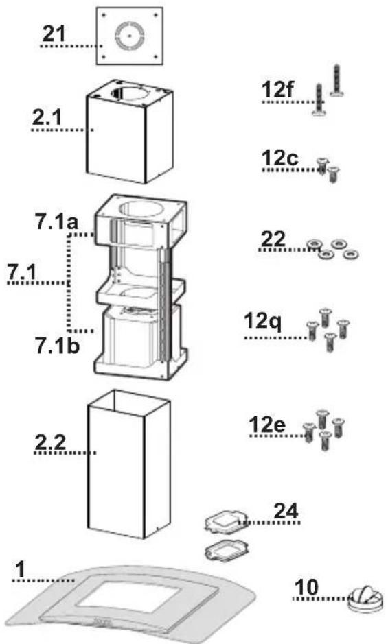
Components
Ref. Qty. Product Components
1 1 Hood Body, complete with: Controls, Light, Filters, Blower.
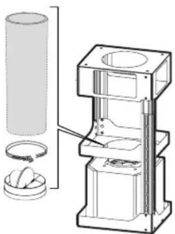
2 1 Telescopic Chimney comprising:
2.1 1 Upper Section
2.2 1 Lower Section
7.1 1 Telescopic frame complete with extractor, consisting of:
7.1a 1 Upper frame
7.1b 1 Lower frame
10 1 Damper ø 5 7/8"
24 1 Junction Box
Ref. Qty. Installation Components
12f 2 Screws 3/16" x 9/16"
12c 2 Screws 1/8" x 1/4"
12e 4 Screws 1/8" x 3/8"
12q 4 Screws 1/4" x 9/16"
21 1 Drilling template
22 4 1/4" int. dia washers
Qty. Documentation
1 Instruction Manual
Parts needed
- 6" Round Metal ductwork
Available Accessories
- High Ceiling Kit that replaces the upper flue. - sku#HIGH2.
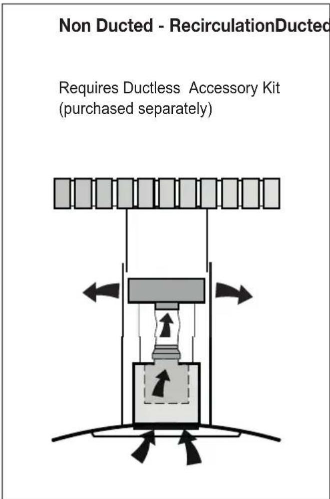
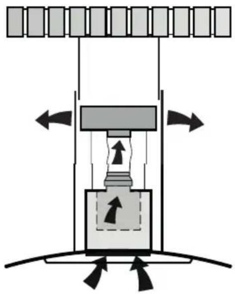
- Ductless Kit - Includes Ductless Diverter, Charcoal Filters, Lower chimney with vent grates - sku# DUCT2
- Activated Charcoal Filter Accessory - sku# FILTER2
- Wireless Remote Control Accessory - REMCTRL2
Choose your ducting method
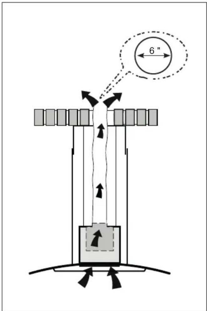
Ventin
Non Ducted - RecirculationDucted Ventin
Requires Ductless Accessory Kit (purchased separately)
natural_image
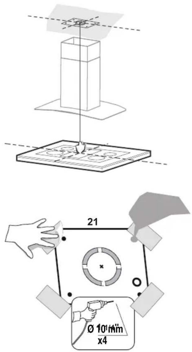
Diagram of a mechanical press or lifting mechanism with directional arrows indicating force or movement (no text or symbols present)1 Do not make any cutouts until you have decided whether this installation will be ducted or non-duct and then plan accordingly.
! WARNING
DUE TO THE SIZE AND WEIGHT OF THIS RANGE-HOOD, THE SUPPORT MUST BE FIRMLY ATTACHED TO THE CEILING. For plaster or sheet rock ceiling, the support must be attached to the joists. If this is not possible, a support structure must be built behind the plaster or sheet rock. The manufacturer assumes no responsibility for injury or damage caused by improper installations.
Put a thick, protective covering over cooktop, set-in range or countertop to protect from damage or dirt.
Determine and clearly mark with a pencil on the ceiling where the rangehood will be installed.
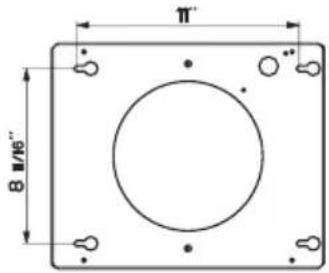
A template 21 for mounting the support is supplied in the carton with the support. Use this template to mark holes for support on the ceiling.
Determine and make necessary cuts for the ductwork. The duct opening is shown on the mounting template. Install ductwork before mounting the hood.
Determine the proper location for the Power Supply Cable as indicated on the template. Use a 1 1/4" Drill Bit to make this hole. For the Power Supply Cable. Use caulking to seal around the hole.
A knockout for threading through the Powe Supply from the ceiling is located on the top of the frame. Do not connect the Power Cable to the Wiring Box or power up the hood at this time. Run enough power cable from the ceiling to reach the wiring box on the hood.
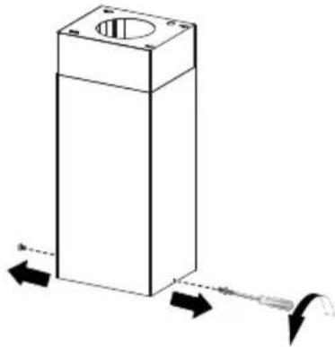
Chimney Flues Must Be Removed Before Installing the Hood
2
natural_image
3D diagram of a rectangular block with a circular hole and directional arrows indicating force or movement (no text or symbols)
natural_image
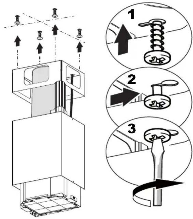
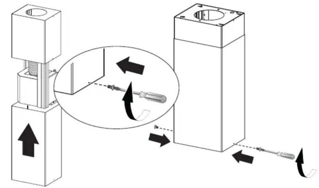
Mechanical device with a downward arrow indicator (no text or symbols present)Loosen the two screws fastening the lower chimney and remove this from the lower frame.
3
natural_image
Technical line drawing of a mechanical assembly with arrows indicating motion (no text or symbols)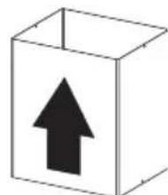
natural_image
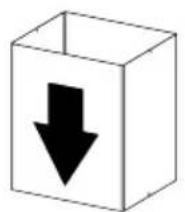
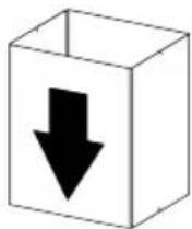
Simple 3D box illustration with an upward arrow inside (no text or symbols)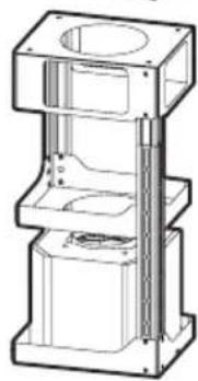
natural_image
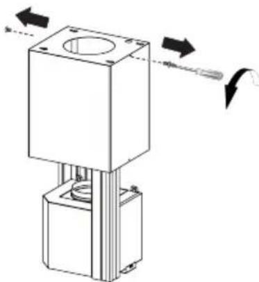
Technical line drawing of a mechanical assembly with cylindrical components and mounting brackets (no text or symbols)Loosen the two screws fastening the upper chimney and remove this from the upper frame.
4
If you need to adjust the height of the frame, proceed as follows:
- Unfasten the metric screws joining the two columns, located at the sides of the frame (1,2,3,4,5,6).
- Adjust the frame to the height required, then refit all the screws removed as above.
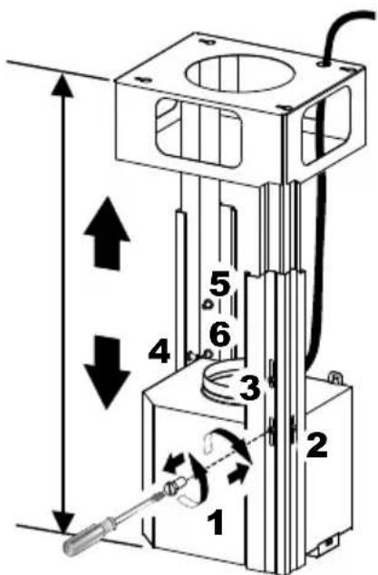
5
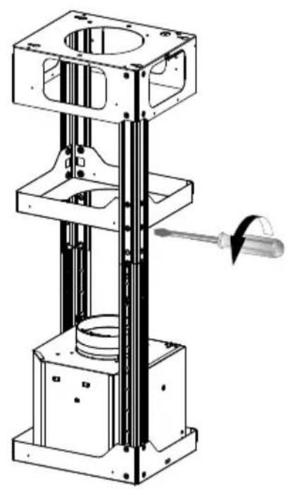
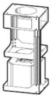
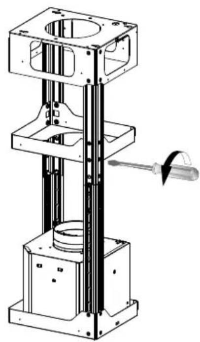
REMOVING THE MIDDLE TRESTLE COMPONENT
NOTE: The chimney structure can reduce down to a 27" minimum height. To reduce the height, the middle section of the support structure needs to be removed.
Out of the box, the minimum chimney length is 32".
Insure the the installation process outlined in the U&C is followed and there is sufficient stability with the middle section removed.
natural_image
Technical line drawing of a mechanical testing apparatus with a tool inserted (no text or symbols)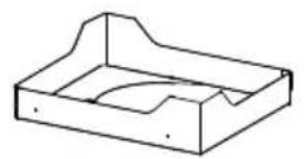
natural_image
Simple line drawing of a rectangular box with a curved cutout on top (no text or symbols)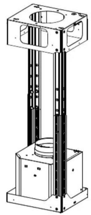
natural_image
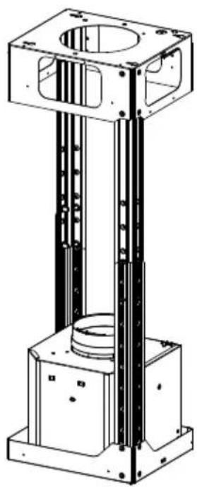
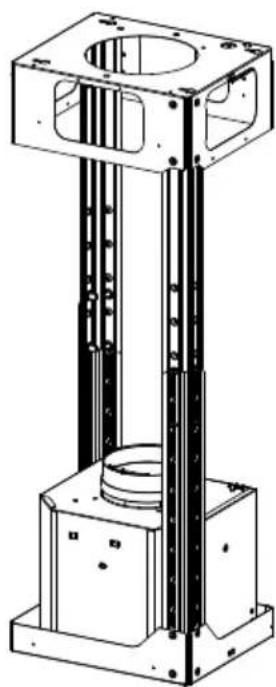
Technical line drawing of a mechanical assembly with vertical supports and a central cylindrical component (no text or symbols)6
Upper Flue Must Be In Place Before Proceeding
natural_image
Technical line drawing of a mechanical assembly with cylindrical components and mounting brackets (no text or symbols)After the regulation for height adjustment, insert the upper chimney stack from above, and leave it running free on the frame.
7
Only for Ducted Venting Installation
natural_image
Technical line drawing of a mechanical testing setup with cylindrical component and multi-tiered platform (no text or symbols)Install Damper that is included with the Hood before connecting to the ductwork.
8
Now take either your wood screws or bolts depending on your set-up and screw all four into the pilot holes and leave 1/4" of the heads exposed.
Next install a UL or CSA listed strain relief in the wiring box so that the screws can be tightened after the chimney support is attached to the ceiling.
Now lift the chimney support into it's final position and feed the electrical supply through the strain relief.
Next position the chimney support so that the large end of the keyhole slots are over the ceiling attachment screws or bolts. Then push the chimney support so that the bolts are in the neck of the slots. Tighten all four screws or bolts securely.
- The frame mountings must be secure to withstand the weight of the hood and any stresses caused by the occasional side thrust applied to the device. On completion, check that the base is stable, even if the frame is subjected to bending.
- In all cases where the ceiling is not strong enough at the suspension point, the installer must provide strengthening using suitable plates and backing pieces anchored to the structurally sound parts.
8
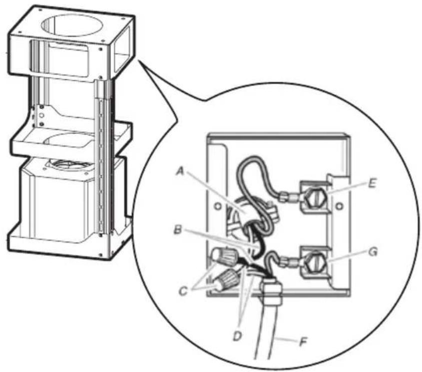
Installation of wiring connection
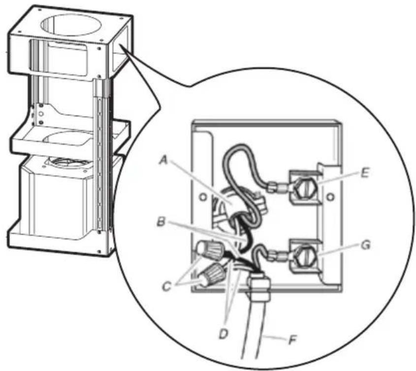
Remove the cover from the field wiring compartment. DO NOT turn on the power until installation is complete! Connect the Power Supply Cable to the rangehood. Connect the Green (Green and Yellow) ground wire under the Green grounding screw. Attach the White lead of the power supply to the White lead of the rangehood with a twist-on type wire connector.
Attach the Black lead of the power supply to the Black lead of the rangehood with a twist-on type wire connector.
Replace the field wiring compartment cover and the grease filters.
A. Home power supply cable
B. Black wires
C. UL listed wire connectors
D. White wires
E. Green (or bare) ground wire from home power supply connected to green ground screw
F. Range hood power supply cable
G. Range hood power supply cable connected to green ground screw
9
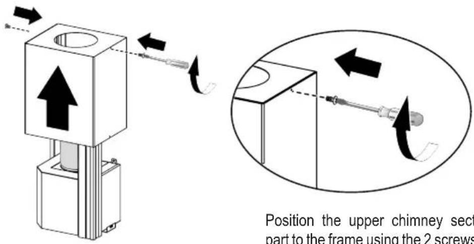
Position the upper chimney section and fix the upper part to the frame using the 2 screws removed previously.
10
Similarly, position the lower chimney section and fix the lower part to the frame using the 2 screws removed previously.
11
Only For Ductless Installations
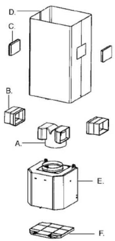
Ductless installations require a Ductless Conversion Kit whose components are pictured in FIGURE 12.
Do not use the DAMPER for ductless installations. The LOWER CHIMNEY COVER should be discarded and replaced by the new one with holes from the Ductless Conversion Kit (D in FIGURE 12).
As indicated in FIGURE 12, place the DUCTLESS DIVERTER (A) over the exhaust opening of the EASY CUBE (E). Fit the DUCTLESS DIVERTER EXTENSIONS HORIZONTAL (B) into the DIVERTER (A).
Attachment of Hood Canopy
12
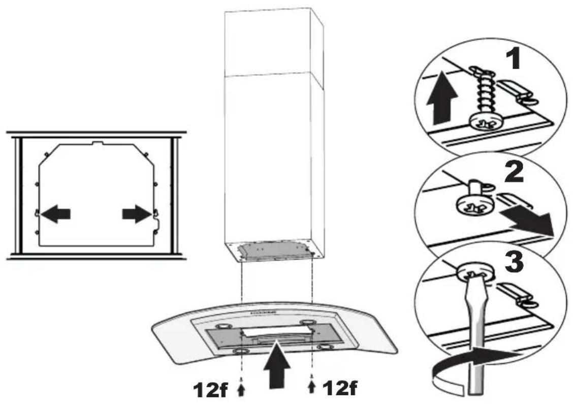
Screw the 2 screws 12f half way into the holes provided in the sides of the bottom of the frame.
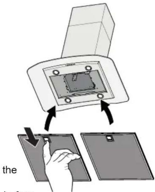
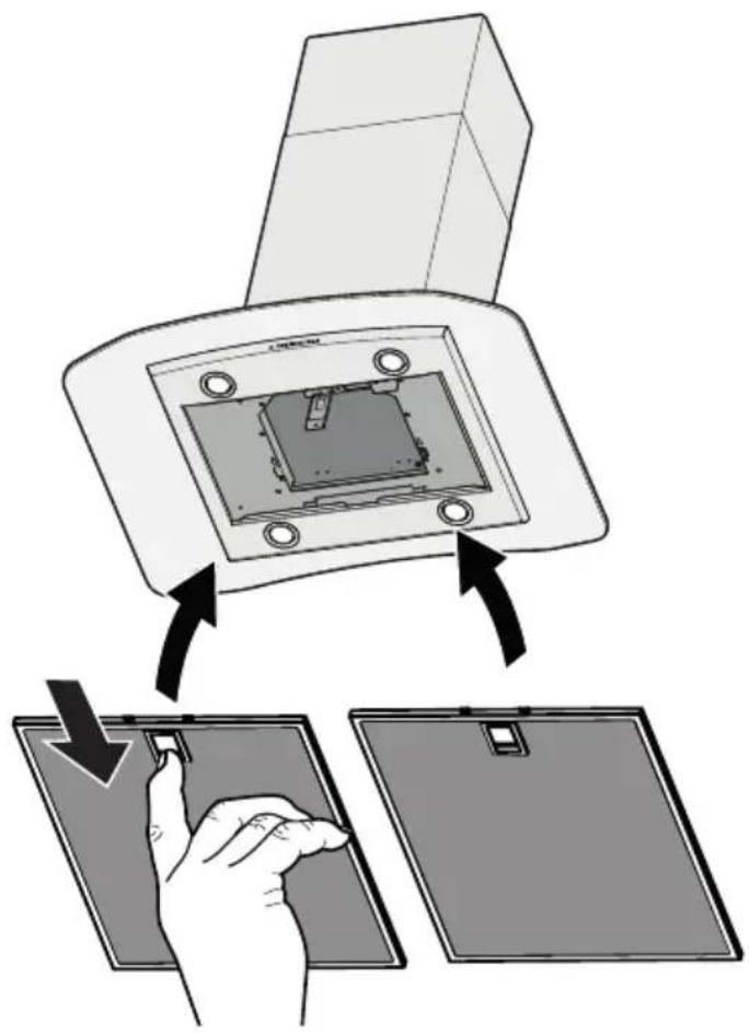
Remove the grease filters from the hood canopy.
Remove any activated charcoal filters.
Lift the hood canopy and engage the screws 12f in the slots as far as they will go.
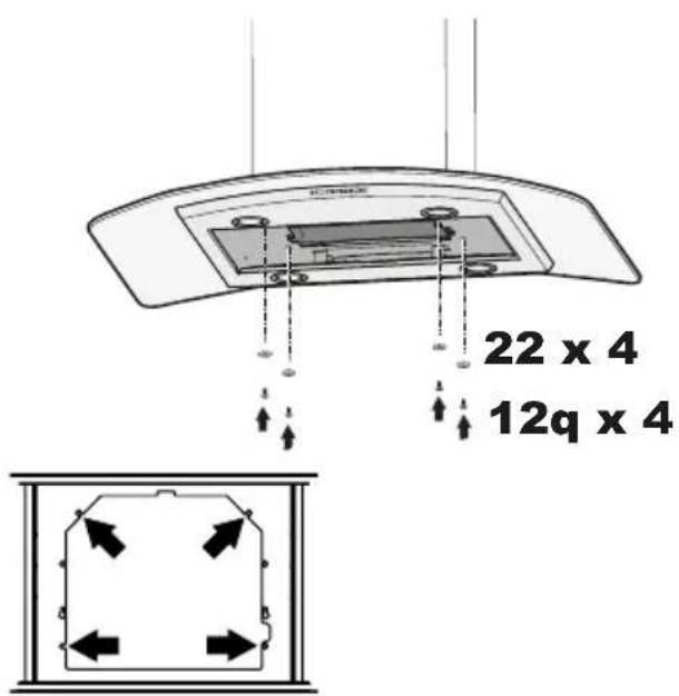
Working from below, fix the hood canopy to the frame where indicated, using the 4 screws 12q and 4 washers 22 provided, then tighten all the screws securely.
13
Make the Internal Electrical Connection
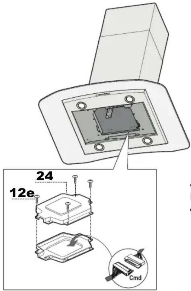
Connect the control connector Cmd. Place the connectors in the junction box 24 and close it using the 4 screws provided.
14
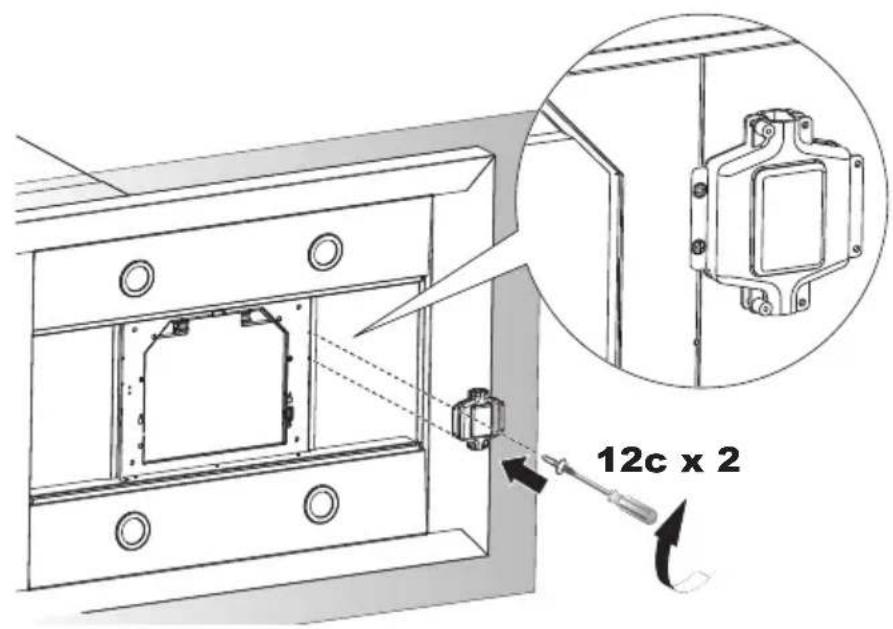
Fix the junction box to the hood body using the 2 screws 12c provided.
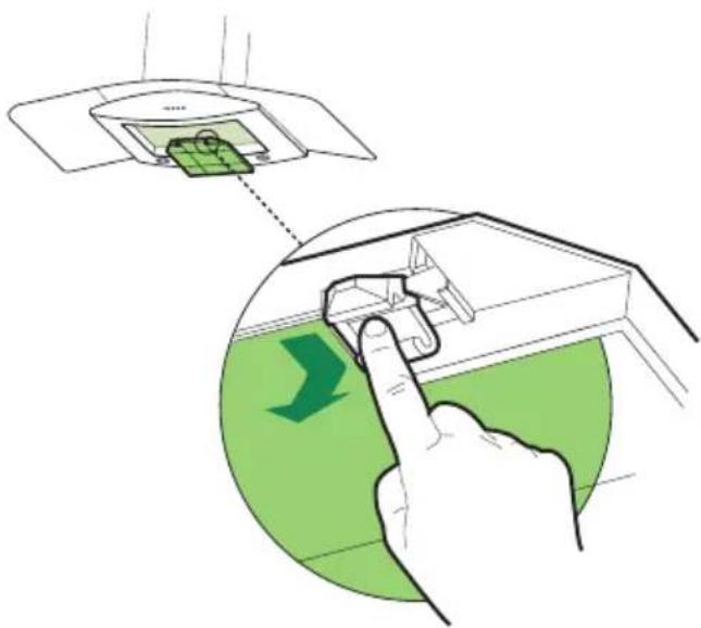
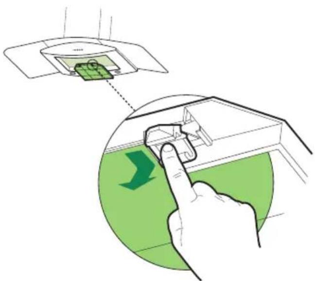
14 For Non-Ducted Recirculation Option
Attach a
charcoal
filter in the
correct
position and
block it by
the fixing
hooks as
shown.
Unlock the fixing hooks (towards the back of the insert hood) to remove.
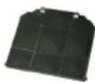
Required Activated Charcoal Filter
Accessory - sku # - FILTER2
(purchased separately)
15
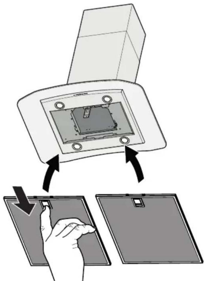
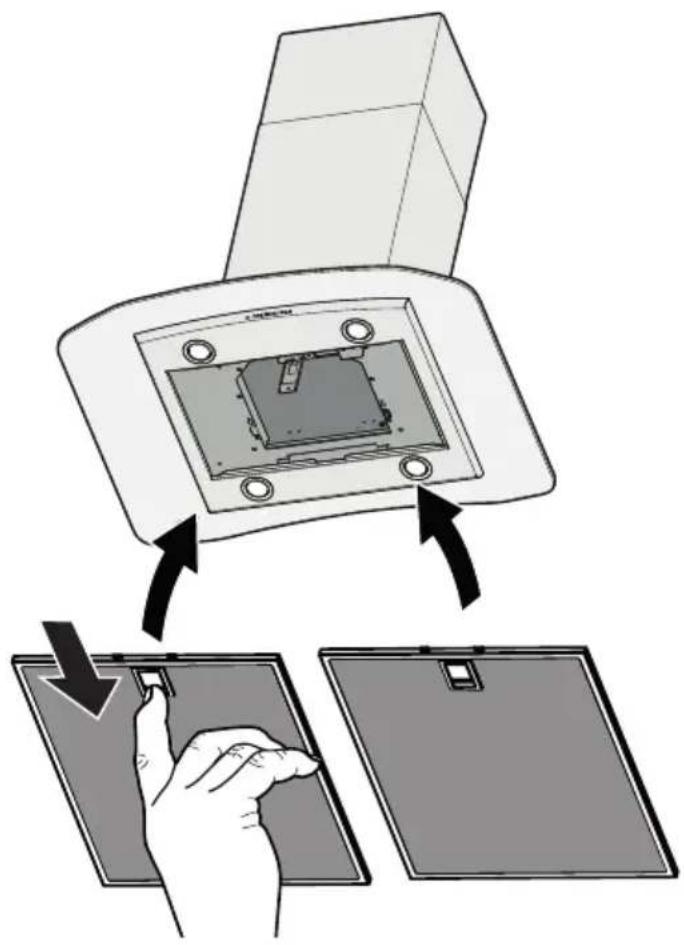
Reinstall the grease filters from the hood canopy.
USE AND CARE INFORMATION
For Best Results
Start the rangehood several minutes before cooking to develop proper airflow. Allow the rangehood to operate for several minutes after cooking is complete to clear all smoke and odors from the kitchen.
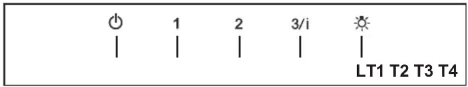
T1. Fan off button: turn the blower Off. The fan can be operated by pressing any of the fan setting buttons. Hold down this button for 2 seconds to activate Delay off function which will keep the fan on for 15 minutes and automatically shut off.
T2. Fan settings buttons: Low speed.
T3. Fan settings buttons: Medium speed.
T4. Fan settings buttons: High speed / Intensive speed.
Hold down the button for 2 seconds to activate the intensive speed, which is timed to run for 10 minutes. At the end of this time it will automatically return to the speed set before. Suitable to deal with maximum levels of cooking fumes.
L. Light button: On/Off switch for the lights.
NOTE: If your product has had a CFM adjustment, refer to the CFM adjustment manual for the information. Some motor speeds or functions may be reduced.
Cleaning metal grease filters
The filters must be cleaned every 2 months of operation, or more frequently for particularly heavy usage, and can be washed in a dishwasher.
- Remove the Filters one at a time, pushing them towards the back of the unit and at the same time pulling downward.
- Wash the Filters without bending them, and leave them to dry completely before replacing. (If the surface of the filter changes colour as time goes by, this will have absolutely no effect on the efficiency of the filter itself.)
- Replace, taking care to ensure that handle faces forwards.
- No water can be present in filters installing back in hood.
before
Replacing Activated Charcoal Filter
The filter is not washable and cannot be regenerated, and must be replaced approximately every 4 months of operation, or more frequently for particularly heavy usage.
- Remove the Filters one at a time, pushing them towards the back of the unit and at the same time pulling downward.
- Remove the saturated charcoal filter by releasing the fixing hooks.
• Fit the new filter and fasten it in its correct position. - Replace, taking care to ensure that the handle faces forwards. "When used in recirculation mode, to Reduce the Risk of Fire and Shock use only conversion kit Model FILTER 2".
Lighting Unit
- LED lights must be replaced by Faber factory authorized service.
Wiring Diagram
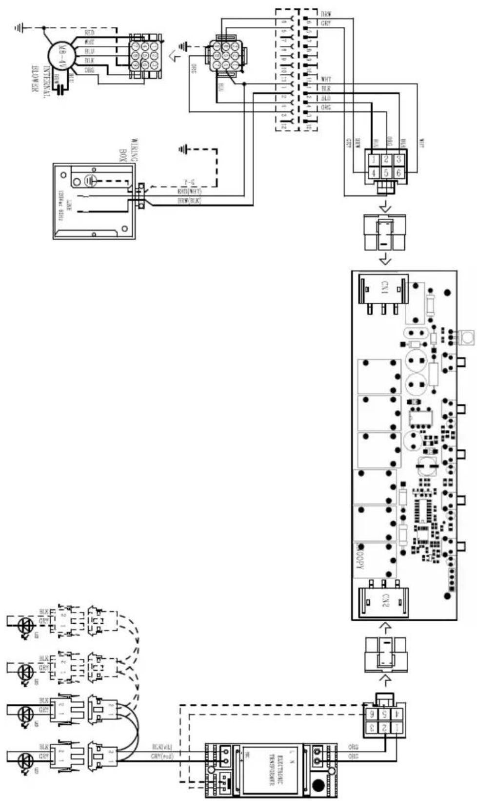
FABER
FABER CONSUMER WARRANTY & SERVICE
All Faber products are warranted against any defect in materials or workmanship for the original purchaser for a period of 1 year from the date of original purchase (requires proof of purchase). This warranty covers labor and replacement parts. Faber, at its option, may repair or replace the product or components necessary to restore the product to good working condition. To obtain warranty service, contact the dealer from whom you purchased the range hood, or the local Faber distributor. If you cannot identify a local Faber distributor, contact us at (508) 358-5353 for the name of a distributor in your area.
The following is not covered by Faber's warranty:
- Service calls to correct the installation of your range hood, to instruct you how to use your range hood, to replace or repair house fuses or to correct house wiring or plumbing.
- Service calls to repair or replace range hood light bulbs, fuses or filters. Those consumable parts are excluded from warranty coverage.
- Repairs when your range hood is used for other than normal, single-family household use.
- Damage resulting from accident, alteration, misuse, abuse, fire, flood, acts of God, improper installation, installation not in accordance with electrical or plumbing codes or Faber documentation, or use of products not approved by Faber.
- Replacement parts or repair labor costs for units operated outside the United States or Canada, including any non-UL or C-UL approved Faber range hoods.
- Repairs to the hood resulting from unauthorized modifications made to the range hood.
- Expenses for travel and transportation for product service in remote locations and pickup and delivery charges. Faber range hoods should be serviced in the home.
THIS WARRANTY DOES NOT ALLOW RECOVERY OF INCIDENTAL OR CONSEQUENTIAL DAMAGES, INCLUDING, WITHOUT LIMITATION, DIRECT, INDIRECT, INCIDENTAL, SPECIAL OR CONSEQUENTIAL DAMAGES, PERSONAL INJURY/WRONGFUL DEATH OR LOST PROFITS FABER WARRANTY IS LIMITED TO THE ABOVE CONDITIONS AND TO THE WARRANTY PERIOD SPECIFIED HEREIN AND IS EXCLUSIVE. EXCEPT AS EXPRESSLY SPECIFIED IN THIS AGREEMENT, FABER DISCLAIMS ALL EXPRESS OR IMPLIED CONDITIONS, REPRESENTATIONS, AND WARRANTIES INCLUDING, WITHOUT LIMITATION, ANY IMPLIED WARRANTIES OF MERCHANTABILITY OR FITNESS FOR A PARTICULAR PURPOSE.
This warranty gives you specific legal rights that may vary from state to state.
Model#:
Serial #: ____
January 4, 2016
VEUILLEZ LIRE ET CONSERVER LA PRÉSENTE NOTICE AVANT DE COMMENCER L'INSTALLATION DE LA HOTTE DE CUISINE
AVERTISSEMENT : POUR RÉDUIRE LE RISQUE D'UN FEU DE GRAISSE SUR LA TABLE DE CUISSON :
National Fire Protection Association
Batterymarch Park

PIÈCES PRINCIPALES
Composants
12c 2 Vis 1/8" x 1/4"
12e 4 Vis 1/8" x 3/8"
12q 4 Vis 1/4" x 9/16"
natural_image
Diagram of a mechanical press or actuator mechanism with directional arrows indicating motion (no text or symbols present)
natural_image
3D diagram of a rectangular block with a circular hole and directional arrows indicating force or movement (no text or symbols)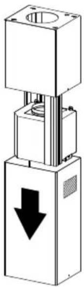
natural_image
Mechanical device with a downward arrow indicator (no text or symbols present)natural_image
Technical line drawing of a mechanical assembly with arrows indicating motion or force direction (no text or symbols)
natural_image
Simple 3D box illustration with an upward arrow inside, no text or symbols present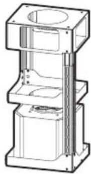
natural_image
Technical line drawing of a mechanical assembly with three stacked components (no text or symbols)REMOVING THE MIDDLE TRESTLE COMPONENT
NOTE: The chimney structure can reduce down to a 27" minimum height. To reduce the height, the middle section of the support structure needs to be removed.
Out of the box, the minimum chimney length is 32".
Insure the the installation process outlined in the U&C is followed and there is sufficient stability with the middle section removed.
natural_image
Technical line drawing of a mechanical lifting or mounting assembly with a tool inserted (no text or symbols)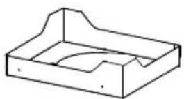
natural_image
Technical line drawing of a mechanical lifting or mounting bracket assembly (no text or symbols)6
Upper Flue Must Be In Place Before Proceeding
natural_image
Technical line drawing of a mechanical assembly with three stacked components (no text or symbols)After the regulation for height adjustment, insert the upper chimney stack from above, and leave it running free on the frame.
7
Only for Ducted Venting Installation

natural_image
Technical line drawing of a mechanical testing setup with cylindrical component and multi-tiered platform (no text or symbols)Install Damper that is included with the Hood before connecting to the ductwork.
8

Now take either your wood screws or bolts depending on your set-up and screw all four into the pilot holes and leave 1/4" of the heads exposed.
Next install a UL or CSA listed strain relief in the wiring box so that the screws can be tightened after the chimney support is attached to the ceiling.
Now lift the chimney support into it's final position and feed the electrical supply through the strain relief.
Next position the chimney support so that the large end of the keyhole slots are over the ceiling attachment screws or bolts. Then push the chimney support so that the bolts are in the neck of the slots. Tighten all four screws or bolts securely.
- The frame mountings must be secure to withstand the weight of the hood and any stresses caused by the occasional side thrust applied to the device. On completion, check that the base is stable, even if the frame is subjected to bending.
- In all cases where the ceiling is not strong enough at the suspension point, the installer must provide strengthening using suitable plates and backing pieces anchored to the structurally sound parts.
8
15
National Fire Protection Association
Batterymarch Park
Quincy, Massachusetts 02269

PARTES PRINCIPALES
Componentes
natural_image
Diagram of a mechanical press or actuator with directional arrows indicating motion (no text or symbols present)ADVERTENCIA
natural_image
3D diagram of a rectangular block with a circular hole and directional arrows indicating force or movement (no text or symbols)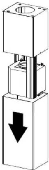
natural_image
Mechanical assembly diagram showing a vertical stack with a downward arrow indicator (no text or symbols present)natural_image
Technical line drawing of a mechanical assembly with arrows indicating motion (no text or symbols)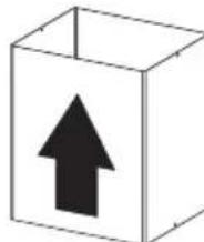
natural_image
Simple 3D box illustration with an upward arrow inside (no text or symbols)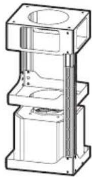
natural_image
Technical line drawing of a mechanical assembly with cylindrical components and mounting brackets (no text or symbols)natural_image
Technical line drawing of a mechanical lifting device with a tool inserted (no text or symbols)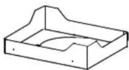
natural_image
Technical line drawing of a mechanical lifting or mounting bracket assembly (no text or symbols)6
natural_image
Technical line drawing of a mechanical assembly with layered components (no text or symbols)natural_image
Technical line drawing of a mechanical assembly with cylindrical components and a multi-tiered platform (no text or symbols)natural_image
Technical diagram of a mechanical assembly with mounting holes and internal components (no text or labels)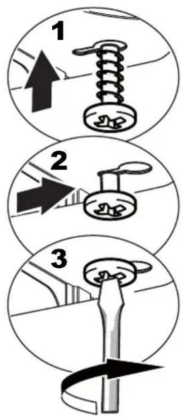
natural_image
Mechanical assembly diagram showing a square block with an upward arrow and a tool, no text or symbols present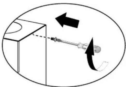
natural_image
Diagram showing a screwdriver interacting with a surface, with arrows indicating motion direction (no text or symbols)17