
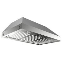
Tender 90 X - Range hood FABER - Free user manual and instructions
Find the device manual for free Tender 90 X FABER in PDF.


| Product Type | Range Hood |
| Brand | Faber |
| Model | Tender 90 X |
| Width | 90 cm |
| Height (min-max) | 60-110 cm |
| Depth | 50 cm |
| Weight | 15 kg |
| Power Supply | 220-240 V / 50 Hz |
| Motor Power | 200 W |
| Max Airflow | 650 m³/h |
| Noise Level (max) | 65 dB(A) |
| Number of Speeds | 3 |
| Lighting | 2 x 20 W Halogen |
| Filter Type | Aluminum Grease Filter |
| Charcoal Filter | Optional (sold separately) |
| Control Type | Push Button |
| Exhaust Diameter | 150 mm |
| Energy Class | B |
| Installation Type | Wall-mounted |
| Material | Stainless Steel |
| Ducted Mode | Yes |
| Recirculation Mode | Yes (with charcoal filter) |
| Warranty | 2 years |
Frequently Asked Questions - Tender 90 X FABER
User questions about Tender 90 X FABER
0 question about this device. Answer the ones you know or ask your own.
Ask a new question about this device
Download the instructions for your Range hood in PDF format for free! Find your manual Tender 90 X - FABER and take your electronic device back in hand. On this page are published all the documents necessary for the use of your device. Tender 90 X by FABER.
USER MANUAL Tender 90 X FABER
Instructions Manual
SAFETY INFORMATION......4
CHARACTERISTICS 7
INSTALLATION 9
USE 12
CARE AND CLEANING 13
INDEX
EN
For your safety and correct operation of the appliance, read this manual carefully before installation and use. Always keep these instructions with the appliance even if you move or sell it. Users must fully know the operation and safety features of the appliance.

The wire connection has to be done by a specialized technician.
- The manufacturer will not be held liable for any damages resulting from incorrect or improper installation.
- The minimum safety distance between the cooker top and the extractor hood is 650 mm (some models can be installed at a lower height, please refer to the paragraphs on working dimensions and installation).
- If the instructions for installation of the gas hob specify a greater distance, this must be respected.
- Check that the mains voltage corresponds to that indicated on the rating plate fixed to the inside of the hood.
- Means for disconnection must be incorporated in the fixed wiring in accordance with the wiring rules.
- For Class I appliances, check that the domestic power supply guarantees adequate earthing.
- Connect the extractor to the exhaust flue through a pipe of minimum diameter 120 mm. The route of the flue must be as short as possible.
- Regulations concerning the discharge of air have to be fulfilled.
- Do not connect the extractor hood to exhaust ducts carrying combustion fumes (boilers, fireplaces, etc.).
- If the extractor is used in conjunction with non-electrical appliances (e.g. gas burning appliances), a sufficient degree of aeration must be guaranteed in the room in order to prevent the backflow of exhaust gas. When the cooker hood is used in conjunction with appliances supplied with energy other than electric, the negative pressure in the room must not exceed 0.04 mbar to prevent fumes being drawn back into the room by the cooker hood.
- The air must not be discharged into a flue that is used for exhausting fumes from appliances burning gas or other fuels.
- If the supply cord is damaged, it must be replaced by the manufacturer or its service agent.
- Connect the plug to a socket complying with current regulations, located in an accessible place.
- With regards to the technical and safety measures to be adopted for fume discharging, it is important to closely follow the regulations provided by the local authorities.
⚠ WARNING: Before installing the hood, remove the protective films.
• Use only screws and small parts supplied with the hood.
⚠ WARNING: Failure to install the screws or fixing device in accordance with these instructions may result in electrical hazards.
- Do not look directly at the light through optical devices (binoculars, magnifying glasses...).
- Do not flambé under the range hood; risk of fire.
- This appliance can be used by children aged from 8 years and above and persons with reduced physical, sensory or mental capabilities or lack of experience and knowledge if they have been given supervision or instruction concerning use of the appliance in a safe way and understand the hazards involved. Children shall not play with the appliance. Cleaning and user maintenance shall not be made by children without supervision.
- Children should be supervised to ensure that they do not play with the appliance.
- The appliance is not to be used by persons (including children) with reduced physical, sensory or mental capabilities, or lack of experience and knowledge, unless they have been given supervision or instruction. ⚠️ Accessible parts may become hot when used with cooking appliances.
- Clean and/or replace the Filters after the specified time period (Fire hazard). See paragraph Care and Cleaning.
- There shall be adequate ventilation of the room when the range hood is used at the same time as appliances burning gas or other fuels (not applicable to appliances that only discharge the air back into the room).
- The symbol on the product or on its packaging indicates that this product may not be treated as household waste. Instead it shall be handed over to the applicable collection point for the recycling of electrical and electronic equipment. By ensuring this product is disposed of correctly, you will help prevent potential negative consequences for the environment and human health, which could otherwise be caused by inappropriate waste handling of this product. For more detailed information about recycling of this product, please contact your local city office, your household waste disposal service or the shop where you purchased the product.
CHARACTERISTICS
Components
Ref. Q.ty Product Components
| 1 | 1 | Hood Body, complete with: Controls, Light, Blower, Filters | |
| 2 | 1 | Telescopic Chimney comprising: | |
| 2.1 | 1 | Upper | Section |
| 2.2 | 1 | Lower | Section |
| 8 | 1 | Air Outlet Grill ø 125 mm | |
| 9 | 1 | Reducer Flange ø 150-120 mm | |
Ref. Q.ty Installation Components
| 7.1 2 Hood Body Fixing Brackets | |||
| 7.2.1 2 Upper Chimney Section Fixing Brackets | |||
| 11 | 8 | Wall | Plugs |
| 12a | 8 | Screws 4.2 x 44,4 | |
| 12c | 6 | Screws 2.9 x 9.5 | |
| 12d | 2 | Screws M4 x 25 | |
| 12e | 6 | Screws 2.9 x 9.5 | |
| Q.ty | Documentation | |
| 1 | Instruction | Manual |

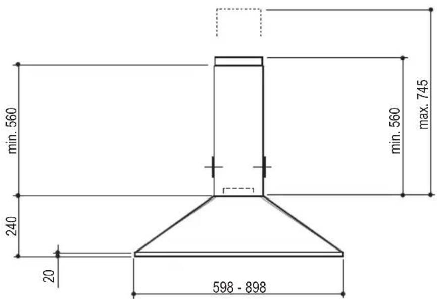

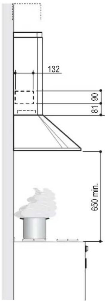
Wall drilling and bracket fixing

Wall marking:
- Draw a vertical line on the supporting wall up to the ceiling, or as high as practical, at the centre of the area in which the hood will be installed.
- Draw a horizontal line at 650 mm above the hob for installation without the back panel, or at height H (height of the visible part of the panel) for installation with the back panel.
- Place bracket 7.2.1 on the wall as shown about 1-2 mm from the ceiling or upper limit, aligning the centre (notch) with the vertical reference line. • Mark the wall at the centres of the holes in the bracket.
- Place bracket 7.2.1 on the wall as shown at X mm below the first bracket (X = height of the upper chimney section supplied), aligning the centre (notch) with the vertical line.
- Mark the wall at the centers of the holes in the bracket.
- Place bracket 7.1 as shown, 110 mm from the vertical reference line and 180 mm above the horizontal reference line. Mark the centers of the holes in the bracket.
- Repeat this operation on the other side.
REAR PANEL (OPTIONAL)
The rear panel must be fitted before fixing the hood body and, if it is to be fixed at both top and bottom, must be fitted at the correct height prior to installing the bases. As this operation is rather complex, it should be carried out either by the kitchen installer or a qualified person who knows the final dimensions of the units.
For fixing at the top only, proceed as follows:
- Rest the back panel on the base, inserting the lower plate between the upper surface and the wall, centering it on the vertical reference line.
- Mark the centers of the two holes in the upper plate.
- Drill 8 mm diameter holes at all the center points marked.
- Insert the wall plugs 11 in the holes. Fix the brackets using the 12a screws supplied. Fix the back panel (where present) using the 12a screws supplied.
Mounting the hood body
- Screw the two screws 12d supplied onto the brackets 7.1.
- Hook the hood body onto the bracket 7.1, centering it around the vertical line.
- Use the adjusting screws 12d underneath the hood to level the hood body.

Connections
DUCTED VERSION AIR EXHAUST SYSTEM
When installing the ducted version, connect the hood to the chimney using either a flexible or rigid pipe of 150 or 120 mm diameter, the choice of which is left to the installer.
- To install a 120 mm diameter air exhaust connection, insert the reducer flange 9 on the hood body outlet.
- Fix the pipe in position using sufficient pipe clamps (not supplied).
- Remove possible charcoal filters.

RECIRCULATION VERSION AIR OUTLET
- Cut a hole of 125 mm diameter in any shelf that may be positioned over the hood.
- Insert the reducer flange 9 on the hood body outlet.
- Connect the flange to the outlet on the shelf over the hood by using a flexible or rigid pipe of 120 mm diameter.
- Fix the pipe in position using sufficient pipe clamps (not supplied).
- Fix the air outlet grid 8 on the recirculation air outlet by using the 2 screws 12e (2.9 x 9.5) provided.
- Ensure that the activated charcoal filters have been inserted.

ELECTRICAL CONNECTION
- Connect the hood to the mains through a two-pole switch having a contact gap of at least 3 mm.
- Remove the grease filters (see paragraph Maintenance) being sure that the connector of the feeding cable is correctly inserted in the socket placed on the side of the fan.

Chimney assembly
Upper exhaust Chimney
- Slightly widen the two sides of the upper chimney and hook them behind the brackets 7.2.1, making sure that they are well seated.
- Secure the sides to the brackets using the 4 screws 12c (2.9 x 9.5) supplied.
Lower exhaust Chimney
- Slightly widen the two sides of the chimney and hook them between the upper chimney and the wall, making sure that they are well seated.
- Fix the lower part laterally to the hood body using the 2 screws 12c (2.9 x 9.5) supplied.


L Light Switches the lighting system on and off
M Motor Switches the extractor motor on and off
V Speed Sets the operating speed of the extractor:
- Low speed, used for a continuous and silent air change in the presence of light cooking vapour.
- Medium speed, suitable for most operating conditions given the optimum treated air flow/noise level ratio.
- Maximum speed, used for eliminating the highest cooking vapour emission, including long periods.
Grease filters
CLEANING METAL SELF- SUPPORTING GREASE FILTERS
- The filters must be cleaned every 2 months of operation, or more frequently for particularly heavy usage, and can be washed in a dishwasher.
- Remove the filters one at a time by pushing them towards the back of the group and pulling down at the same time.
- Wash the filters, taking care not to bend them. Allow them to dry before refitting.
- When refitting the filters, make sure that the handle is visible on the outside.

Activated charcoal filter (Recirculation version)
These filters are not washable and cannot be regenerated, and must be replaced approximately every 4 months of operation, or more frequently with heavy usage.
REPLACING THE ACTIVATED CHARCOAL FILTER
- Remove the metal grease filters
- Remove the saturated activated charcoal filter as shown (A). • Fit the new filters (B).
- Replace the metal grease filters.

Lighting
LIGHT REPLACEMENT
- Remove the metal grease filters.
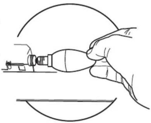
- Unscrew the bulbs and replace them with new ones having the same characteristics.
- Replace the metal grease filters.
| Lamp Power (W) Socket | Voltage (V) Dimension (mm) ILCOS Code | ||||
| [024] | 4 | E14 | 220-240 | 107 x 37 | DRBB/F-4-220-240-E14-35/100 |
 | 5 | GU10 | 230 | 52 x 50 | DRPAR-5/840-220/240-GU10-35/36DRPAR-5/830-220/240-GU10-35/36 |


Lighting
REPLACING THE LIGHT BULBS
| Лампа | Потребление (Вт) | Патрон | Напряжение (В) | Размер (ММ) | Код ILCOS |
| [2024] | 4 | E14 | 220-240 | 107 x 37 | DRBB/F-4-220-240-E14-35/100 |
 | 5 | GU10 | 230 | 52 x 50 | DRPAR-5/840-220/240-GU10-35/36DRPAR-5/830-220/240-GU10-35/36 |
DUCTED VERSION AIR EXTRACTION SYSTEM
Installing the extraction duct
Lighting
REPLACING THE LIGHT
| Pære Forbrug (W) Fatning Spænding (V) Mål (mm) ILCOS art. hr. | |||||
 | 4 E14 220 - 240 107 x 37 | DRBB/F-4-220-240-E14-35/100 | |||
 | 5 GU10 230 | 52 x 50 | DRPAR-5/840-220/240-GU10-35/36DRPAR-5/830-220/240-GU10-35/36 | ||
Recirculation filter (filtering version)
Lighting
REPLACING THE LAMP
| Lampa Förbrukning (W) Sockel Spänning (V) Mått (mm) ILCOS art.nr | |||||
| [400xx] | 4 | E14 | 220-240 | 107 x 37 | DRBB/F-4-220-240-E14-35/100 |
 | 5 | GU10 | 230 | 52 x 50 | DRPAR-5/840-220/240-GU10-35/36DRPAR-5/830-220/240-GU10-35/36 |
Lighting
REPLACING THE LIGHT BULBS
| Lyspære | Forbruk (W) | Sokkel | Spenning (V) | Mål (mm) | ILCOS art.nr. | |
| [COZA] | 4 | E14 | 220-240 | 107 x 37 | DRBB/F-4-220-240-E14-35/100 | |
 | 5 | GU10 | 230 | 52 x 50 | DRPAR-5/840-220/240-GU10-35/36DRPAR-5/830-220/240-GU10-35/36 | |
Installing the flue
Upper flue
Lighting
REPLACING THE LAMPS
| Lamppu Ottoteho (W) Kanta | Jännite (V) | Koko (mm) ILCOS-koodi | |||
| [BYTY] | 4 | E14 | 220-240 | 107 x 37 | DRBB/F-4-220-240-E14-35/100 |
 | 5 | GU10 | 230 | 52 x 50 | DRPAR-5/840-220/240-GU10-35/36DRPAR-5/830-220/240-GU10-35/36 |
Control panel
Lighting
BULB REPLACEMENT
| Typ żarówki | Moc (W) | Mocowanie | Napięcie (V) | Wymiary (mm) | Kod ILCOS |
| [C782] | 4 | E14 | 220-240 | 107 x 37 | DRBB/F-4-220-240-E14-35/100 |
 | 5 | GU10 | 230 | 52 x 50 | DRPAR-5/840-220/240-GU10-35/36DRPAR-5/830-220/240-GU10-35/36 |
CE

- INDEX
- EN
- CHARACTERISTICS
- COMPONENTS
- WALL DRILLING AND BRACKET FIXING
- WALL MARKING
- REAR PANEL (OPTIONAL)
- MOUNTING THE HOOD BODY
- CONNECTIONS
- DUCTED VERSION AIR EXHAUST SYSTEM
- RECIRCULATION VERSION AIR OUTLET
- ELECTRICAL CONNECTION
- CHIMNEY ASSEMBLY
- UPPER EXHAUST CHIMNEY
- LOWER EXHAUST CHIMNEY
- GREASE FILTERS
- CLEANING METAL SELF- SUPPORTING GREASE FILTERS
- ACTIVATED CHARCOAL FILTER (RECIRCULATION VERSION)
- REPLACING THE ACTIVATED CHARCOAL FILTER
- LIGHTING
- LIGHT REPLACEMENT
- REPLACING THE LIGHT BULBS
- DUCTED VERSION AIR EXTRACTION SYSTEM
- INSTALLING THE EXTRACTION DUCT
- REPLACING THE LIGHT
- RECIRCULATION FILTER (FILTERING VERSION)
- REPLACING THE LAMP
- INSTALLING THE FLUE
- UPPER FLUE
- REPLACING THE LAMPS
- CONTROL PANEL
- BULB REPLACEMENT
Brand : FABER
Model : Tender 90 X
Category : Range hood