DIAM30SS - Basket FABER - Free user manual and instructions
Find the device manual for free DIAM30SS FABER in PDF.

User questions about DIAM30SS FABER
0 question about this device. Answer the ones you know or ask your own.
Ask a new question about this device
Download the instructions for your Basket in PDF format for free! Find your manual DIAM30SS - FABER and take your electronic device back in hand. On this page are published all the documents necessary for the use of your device. DIAM30SS by FABER.
USER MANUAL DIAM30SS FABER
natural_image
Line drawing of a 3D pedestal or support structure with no text or symbolsDIAMANTE
(electronic LED controls)
Wall Mount Canopy Rangehood
- Installation Instructions
- Use and Care Information
READ AND SAVE THESE INSTRUCTIONS
The Installer must leave these instructions with the homeowner. The homeowner must keep these instructions for future reference and for local electrical inspectors' use.
READ THESE INSTRUCTIONS BEFORE YOU START INSTALLING THIS RANGEHOOD
WARNING: - TO REDUCE THE RISK OF A RANGE TOP GREASE FIRE:
a) Never leave surface units unattended at high settings. Boilovers cause smoking and greasy spillovers that may ignite. Heat oils slowly on low or medium setting.
b) Always turn hood ON when cooking at high heat or when flambeing food
(i.e. Crepes Suzette, Cherries Jubilee, Peppercorn Beef Flambé).
c) Clean ventilating fans frequently. Grease should not be allowed to accumulate on fan or filter.
d) Use proper pan size. Always use cookware appropriate for the size of the surface element.
WARNING: - TO REDUCE THE RISK OF INJURY TO PERSONS IN THE EVENT OF A RANGE TOP GREASE FIRE, OBSERVE THE FOLLOWING (*):
a) SMOTHER FLAMES with a close-fitting lid, cookie sheet, or metal tray, then turn off the burner. BE CAREFUL TO PREVENT BURNS. If the flames do not go out immediately EVACUATE AND CALL THE FIRE DEPARTMENT.
b) NEVER PICK UP A FLAMING PAN - You may be burned.
c) DO NOT USE WATER, including wet dishcloths or towels - a violent steam explosion will result.
d) Use an extinguisher ONLY if:
1) You know you have a Class ABC extinguisher, and you already know how to operate it.
2) The fire is small and contained in the area where it started.
3) The fire department is being called.
4) You can fight the fire with your back to an exit.
(*) Based on "Kitchen Firesafety Tips" published by NFPA.
ALL WALL AND FLOOR OPENINGS WHERE THE RANGEHOOD IS INSTALLED MUST BE SEALED.
This rangehood requires at least 24" of clearance between the bottom of the rangehood and the cooking surface or countertop. This minimum clearance may be higher depending on local building code. For example, for gas ranges, a minimum of 30" is recommended and may be required. Overhead cabinets on both sides of this unit must be a minimum of 18" above the cooking surface or countertop. Consult the cooktop or range installation instructions given by the manufacturer before making any cutouts.
LISEZ BIEN CETTE FICHE AVANT D'INSTALLER LA HOTTE
Determine which venting method is best for your application. Ductwork can extend either through the wall or the roof.
The length of the ductwork and the number of elbows should be kept to a minimum to provide efficient performance. The size of the ductwork should be uniform. Do not install two elbows together. Use duct tape to seal all joints in the ductwork system. Use caulking to seal exterior wall or floor opening around the cap.
Flexible ductwork is not recommended. Flexible ductwork creates back pressure and air turbulence that greatly reduces performance.
Make sure there is proper clearance within the wall or floor for exhaust duct before making cutouts. Do not cut a joist or stud unless absolutely necessary. If a joist or stud must be cut, then a supporting frame must be constructed
FOR MORE SPECIFIC DUCTWORK INFORMATION, GO TO PAGE 4.
WARNING - To Reduce The Risk Of Fire, Use Only Metal Ductwork.
Cold Weather installations
An additional back draft damper should be installed to minimize backward cold air flow and a nonmetallic thermal break should be installed to minimize conduction of outside temperatures as part of the vent system. The damper should be on the cold air side of the thermal break. The break should be as close as possible to where the vent system enters the heated portion of the house.
WARNING
- Venting system MUST terminate outside the home.
- DO NOT terminate the ductwork in an attic or other enclosed space.
- DO NOT use 4" laundry-type wall caps.
- Flexible-type ductwork is not recommended.
- DO NOT obstruct the flow of combustion and ventilation air.
- Failure to follow venting requirements may result in a fire.
ELECTRICAL REQUIREMENTS
A 120 volt, 60 Hz AC-only electrical supply is required on a separate 15 amp fused circuit. A time-delay fuse or circuit breaker is recommended. The fuse must be sized per local codes in accordance with the electrical rating of this unit as specified on the serial/rating plate located inside the unit near the field wiring compartment. THIS UNIT MUST BE CONNECTED WITH COPPER WIRE ONLY. Wire sizes must conform to the requirements of the National Electrical Code, ANSI/NFPA 70 - latest edition, and all local codes and ordinances. Wire size and connections must conform with the rating of the appliance. Copies of the standard listed above may be obtained from:
National Fire Protection Association
Batterymarch Park
Quincy, Massachusetts 02269
For residential use only.
This appliance should be connected directly to the fused disconnect (or circuit breaker) through flexible, armored or nonmetallic sheathed copper cable. Allow some slack in the cable so the appliance can be moved if servicing is ever necessary. A UL Listed, 1/2" conduit connector must be provided at each end of the power supply cable (at the appliance and at the junction box).
When making the electrical connection, cut a 1 1/4" hole in the wall. A hole cut through wood must be sanded until smooth. A hole through metal must have a grommet.
WARNING - TO REDUCE THE RISK OF FIRE OR ELECTRIC SHOCK, do not use this fan with any solid-state speed control device.
WARNING - TO REDUCE THE RISK OF FIRE, ELECTRICAL SHOCK, OR INJURY TO PERSONS, OBSERVE THE FOLLOWING: Use this unit only in the manner intended by the manufacturer. If you have any questions, contact the manufacturer.
Before servicing or cleaning unit, switch power off at service panel and lock the service disconnecting means to prevent power from being switched on accidentally. When the service disconnecting means cannot be locked, securely fasten a prominent warning device, such as a tag, to the service panel.
CAUTION: For General Ventilating Use Only. Do Not Use To Exhaust Hazardous or Explosive Materials and Vapors.
WARNING - TO REDUCE THE RISK OF FIRE, ELECTRICAL SHOCK, OR INJURY TO PERSONS, OBSERVE THE FOLLOWING: Installation Work And Electrical Wiring Must Be Done By Qualified Person(s) In Accordance With All Applicable Codes And Standards, Including Fire-Rated Construction.
Sufficient air is needed for proper combustion and exhausting of gases through the flue (chimney) of fuel burning equipment to prevent backdrafting. Follow the heating equipment manufacturer's guideline and safety standards such as those published by the National Fire Protection Association (NFPA), and the American Society for Heating, Refrigeration and Air Conditioning Engineers (ASHRAE), and the local code authorities.
When cutting or drilling into wall or ceiling, do not damage electrical wiring and other hidden utilities.
Ducted fans must always be vented to the outdoors.
WARNING
- Electrical ground is required on this rangehood.
- If cold water pipe is interrupted by plastic, nonmetallic gaskets or other materials, DO NOT use for grounding.
• DO NOT ground to a gas pipe. - DO NOT have a fuse in the neutral or grounding circuit. A fuse in the neutral or grounding circuit could result in electrical shock.
- Check with a qualified electrician if you are in doubt as to whether the rangehood is properly grounded.
- Failure to follow electrical requirements may result in a fire.
RÈGLEMENTS D'ÉVACUATION
OPTIONAL ACCESSORIES AVAILABLE
• High Ceiling Chimney Kit
One 40" upper chimney to replace 16 1/8" upper chimney that came with hood part # HIGHDIAM - Stainless
• \*Ductless Conversion Kit
For non-vented installations only
* it is highly recommended that professional style cooking always be vented to the outside part # DUCTDIAM - Stainless
- Replacement Charcoal Filter
For non-vented installations only, replace charcoal filter as needed part # FILTER2
• CFM Reducer Kit
To reduce cfm to below 300 cfm for use in make up air environments part # CFMRED

WARNING
PERSONAL INJURY HAZARD
Because of the weight and size of the rangehood canopy, two or more people are needed to move and safely install the rangehood canopy.
Failure to properly lift rangehood could result in damage to the product or personal injury.
PLAN THE INSTALLATION
This rangehood can be installed as either ducted or ductless. The blower can be vented through the wall or ceiling. To vent through a wall, a 90° elbow is used. When installed ductless, the rangehood vents out of grates on the sides of the chimney. Ductless installations require a Ductless Conversion Kit, available from your dealer.
WARNING! BEFORE MAKING ANY CUTS OR HOLES FOR INSTALLATION, DETERMINE WHICH VENTING METHOD WILL BE USED AND CAREFULLY CALCULATE ALL MEASUREMENTS.
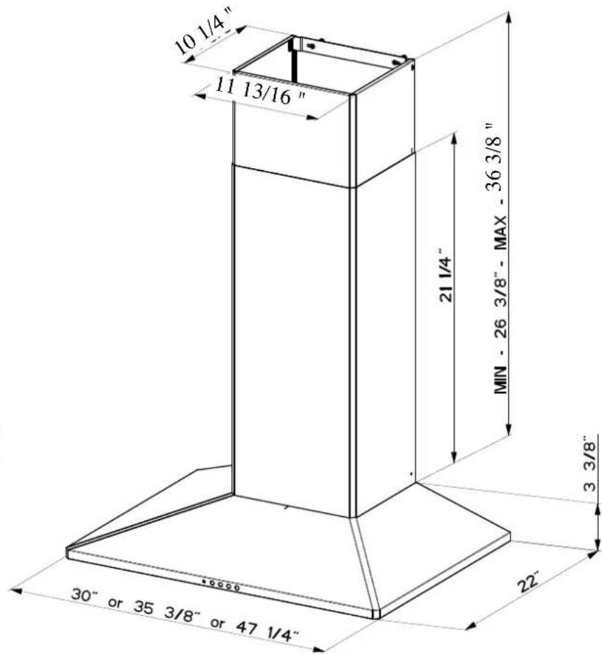
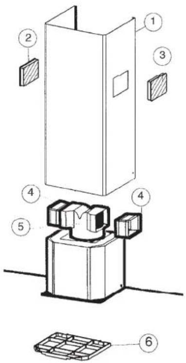
RANGEHOOD COMPONENTS
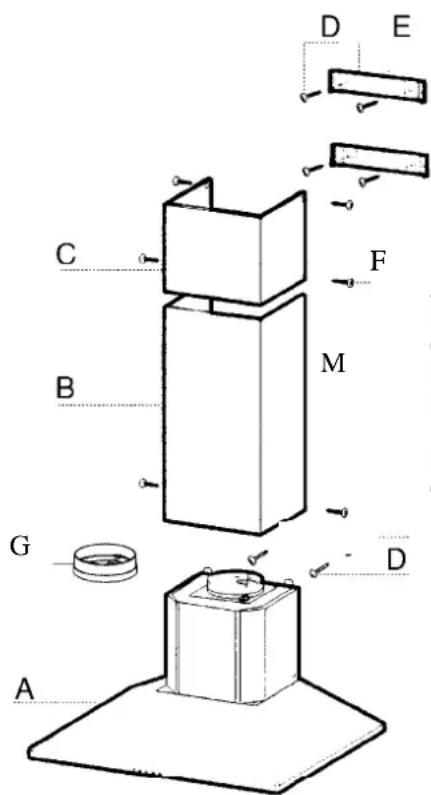
FIGURE 1
A. CANOPY SECTION
B. LOWER CHIMNEY COVER
C. UPPER CHIMNEY COVER
D. MOUNTING SCREWS
E. CHIMNEY MOUNTING BRACKETS
F. CHIMNEY SCREWS
G. DAMPER
CALCULATE THE DUCTRUN LENGTH
The ductrun should not exceed 35 equivalent feet if ducted with the required minimum of 6" round duct. Calculate the length of the ductwork by adding the equivalent feet in FIGURE 2 for each piece of duct in the system. An example is given in FIGURE 3.
| 45° Elbow | 3.0 feet |
| 90° Elbow | 5.0 feet |
| 90° Flat Elbow | 12.0 feet |
| Wall Cap | 0.0 feet |
FIGURE 2
| 9 Feet Straight Duct | 9.0 feet |
| 2 - 90° Elbows | 10.0 feet |
| Wall Cap | 0.0 feet |
| Total System | 19.0 feet |
FIGURE 3
For best results, use no more than three 90° elbows. Make sure that there is a minimum of 24" of straight duct between elbows if more than one is used. Do not install two elbows together. If you must elbow right away, do it as far away from the hood's exhaust opening as possible.
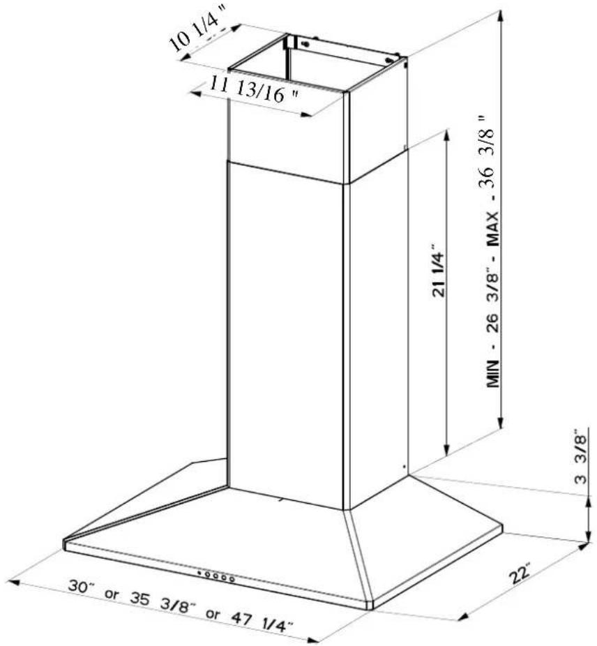
The Diamante chimneys are adjustable and designed to meet varying ceiling heights as indicated in FIGURE 4A. The chimneys can be adjusted for ceilings between 7' 5 3/4" and 8' 10 3/4" depending on the distance between the bottom of the hood and the cooktop (distance x).
For shorter ceilings, have the chimney cover(s) cut at a sheet metal shop. For higher ceiling installations, the High Ceiling Chimney Kit includes a new 40" upper chimney which would replace the 16 1/8" upper chimney that came with the hood.
Note: If 24" or 30" High Backsplash is being installed, the distance between the bottom of the hood and the cooktop (DISTANCE X IN FIGURE 4A) is equal to the height of the Backsplash.
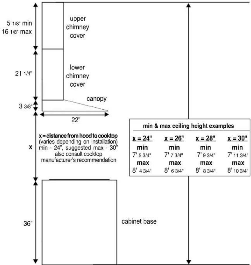
FIGURE 4A DUCTED INSTALLATIONS
DUCTLESS INSTALLATION DIMENSIONS
(not vented to the outside)
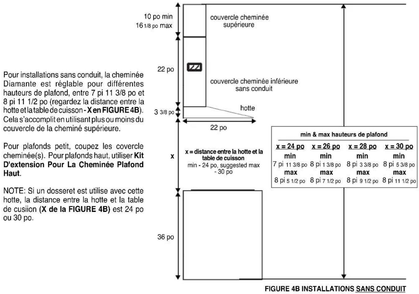
The Diamante chimneys are adjustable and designed to meet varying ceiling heights as indicated in FIGURE 4B. For ductless installations, the chimneys can be adjusted for ceilings between 7' 11 3/8" and 8' 11 1/2" depending on the distance between the bottom of the hood and the cooktop (distance x).
For shorter ceilings, have the chimney cover(s) cut at a sheet metal shop. For higher ceiling installations, the High Ceiling Chimney Kit includes a new 40" upper chimney which would replace the 16 1/8" upper chimney that came with the hood.
Note: If 24" or 30" High Backsplash is being installed, the distance between the bottom of the hood and the cooktop (DISTANCE X IN FIGURE 4B) is equal to the height of the Backsplash.
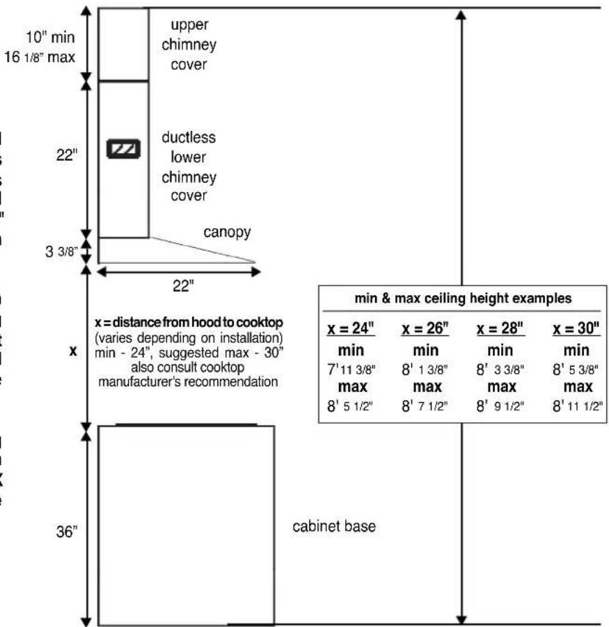
FIGURE 4B DUCTLESS INSTALLATIONS

PREPARE THE WALL
- Disconnect and move freestanding range from cabinet opening to provide easier access to rear wall. Put a thick, protective covering over cooktop, set-in range or countertop to protect from damage or dirt.
- Determine and clearly mark with a pencil the center line on the wall where the rangehood will be installed.
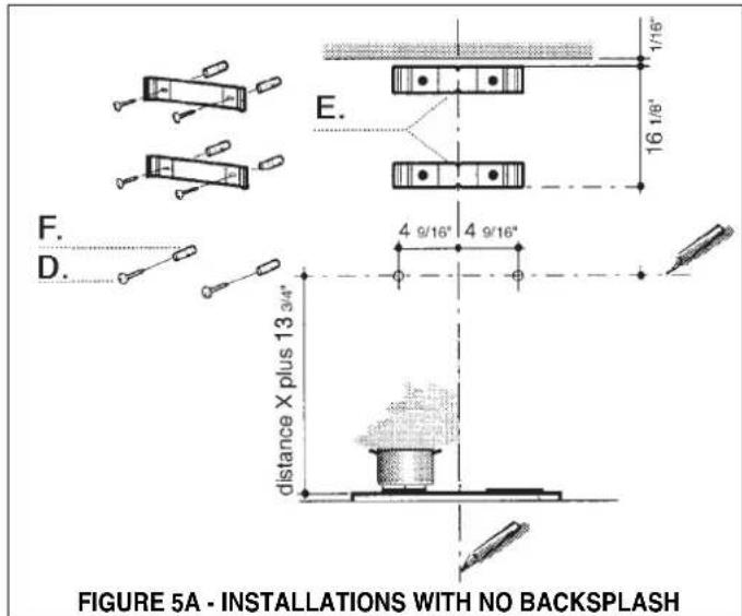
- Based on your ceiling height and/or personal preference, determine the distance you would like between the bottom of the hood and the cooktop (distance X in FIGURE 4A OR 4B). Draw a horizontal line the height of distance X plus 13 3/4" (as indicated in FIGURE 5A - INSTALLATIONS WITH NO BACKSPLASH).
For installations using the 24" or 30" High Backsplash, draw a horizontal line (as indicated in FIGURE 5B-INSTALLATIONS WITH BACKSPLASH) 13 3/4" above the top of the Backsplash.
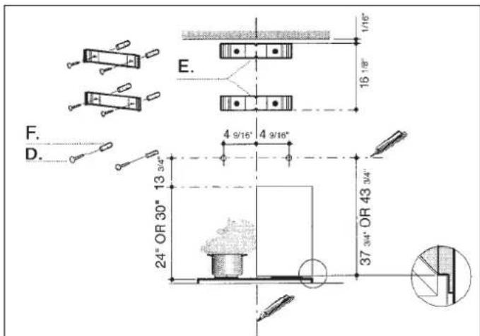
FIGURE 5B - INSTALLATIONS W/ 24" OR 30" HIGH BACKSPLASH
- Place the UPPER CHIMNEY MOUNTING BRACKET (E) on the wall as shown 1/16" from the ceiling, aligning the center notch with the vertical center line. Mark the wall at the centers of the holes in the bracket.
- Place the LOWER CHIMNEY MOUNTING BRACKET (E) on the wall as shown at 16 1/8" below the upper bracket, aligning the center notch with the vertical center line. Mark the wall at the centers of the holes in the bracket.
-
Install the CHIMNEY MOUNTING BRACKETS (E) on the wall using the MOUNTING SCREWS (D) provided.
-
For the most secure installation, the MOUNTING SCREWS (D) which mount the CANOPY SECTION (A in FIGURE 1) should be installed into wood. Mark the wall along the horizontal line 4 9/16" in from the center line on either side (as indicated in FIGURE 5A or 5B) and install the MOUNTING SCREWS into the wall leaving about 1/4" gap between the wall and the head of the screw.
- For ducted installations, determine and make all necessary cuts in the wall for the ductwork. Install the ductwork before the rangehood.
- Determine the proper location for the Power Supply Cable by making sure it:
1) Allows the LOWER CHIMNEY COVER to hide the Field Wiring Compartment.
2) Does not have ductwork blocking your access to the Field Wiring Compartment.
Use a 1 1/4" Drill Bit to make this hole. Run the Power Supply Cable. Use caulking to seal around the hole. DO NOT turn on the power until installation is complete.
INSTALL THE RANGEHOOD
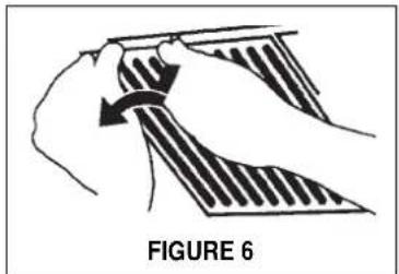
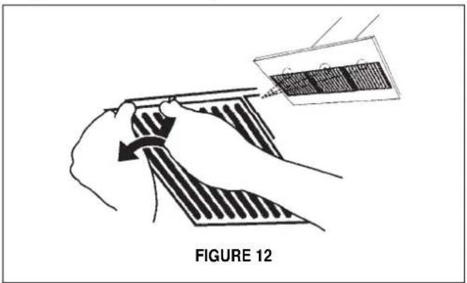
- Remove the grease filters from the unit by pulling the knob forward while turning it to the left, releasing the locking lever.
natural_image
Diagram of a hand holding a folded garment with a curved arrow indicating rotation (no text or symbols)- Before mounting the CANOPY SECTION, tighten the two leveling screws located near the CANOPY SECTION mounting points as indicated in FIGURE 7.
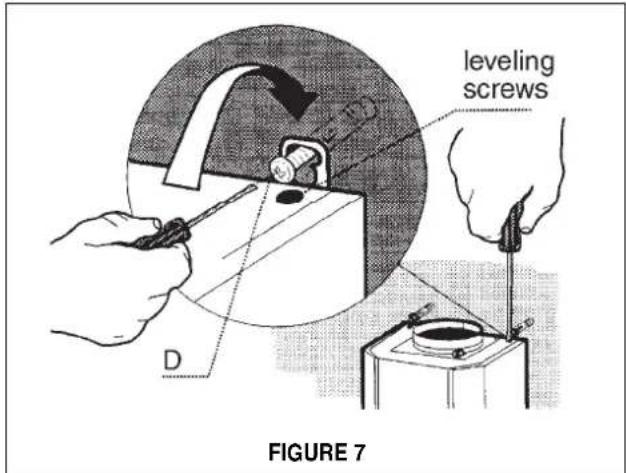
- Hook the body on to the MOUNTING SCREWS (D in FIGURE 7) and fully tighten the MOUNTING SCREWS.
- Adjust the leveling screws to level the CANOPY SECTION.
- For ducted installations, the DAMPER (G in FIGURE 1) must be attached to the exhaust opening on the top of the CANOPY SECTION. Connect the ductwork and seal all connections with duct tape.
PROCEED TO "FOR ALL INSTALLATIONS" ON NEXT PAGE
- LOWER CHIMNEY DUCTLESS
- LEFT VENT GRID
- RIGHT VENT GRID
- DIVERTER EXTENSION HORIZONTAL (2 PIECES)
- DUCTLESS DIVERTER
- CHARCOAL FILTER
FIGURE 8
FOR DUCTLESS INSTALLATIONS
Ductless installations require a Ductless Conversion Kit whose components are pictured in FIGURE 8. Do not use the DAMPER (G in FIGURE 1) for ductless installations. The LOWER CHIMNEY COVER (B in FIGURE 1) should be discarded and replaced by a new one with holes (1 in FIGURE 8).
- As indicated in FIGURE 8, fit the DUCTLESS DIVERTER (5) over the duct outlet. Fit the 2 DIVERTER EXTENSION HORIZONTAL pieces (4) on either side of the DUCTLESS DIVERTER.
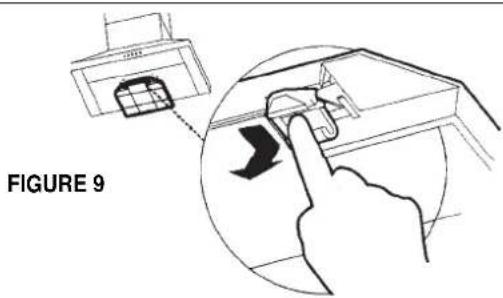
- Install the CHARCOAL FILTER (6) behind the center grease filter opening by inserting and locking into place, as indicated in FIGURE 9.
FOR ALL INSTALLATIONS
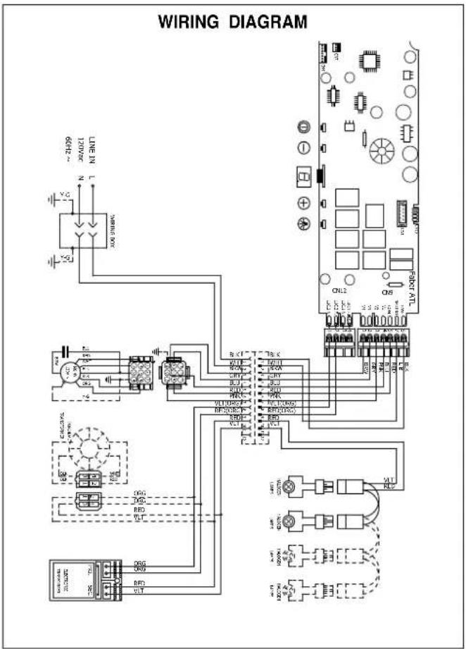
- Remove the cover from the Field Wiring Compartment with a phil-lips screwdriver. Feed the Power Supply Cable through the electrical knockout. Connect the Power Supply Cable to the rangehood cable. Attach the White lead of the power supply to the White lead of the rangehood with a twist-on type wire connector. Attach the Black lead of the power supply to the Black lead of the rangehood with a twist-on type wire connector. Attach the Power Supply Cable grounding lead to the green screw provided. Using the 4 holes provided screw the Field Wiring Compartment to the wall as dictated by your Power Supply Cable location (screws not provided). Replace the cover.
- Install the UPPER CHIMNEY COVER (C in FIGURE 10) by slightly widening the two sides and hooking them behind the CHIMNEY MOUNTING BRACKETS (E). Secure the sides to the CHIMNEY MOUNTING BRACKETS with the 4 CHIMNEY SCREWS (G).
- Install the LOWER CHIMNEY COVER (B) by slightly widening the two sides of the LOWER CHIMNEY COVER and hooking them between the UPPER CHIMNEY COVER and the wall making sure that it fits snugly. Secure the LOWER CHIMNEY COVER to the CANOPY SECTION (A) with 2 CHIMNEY SCREWS (G).
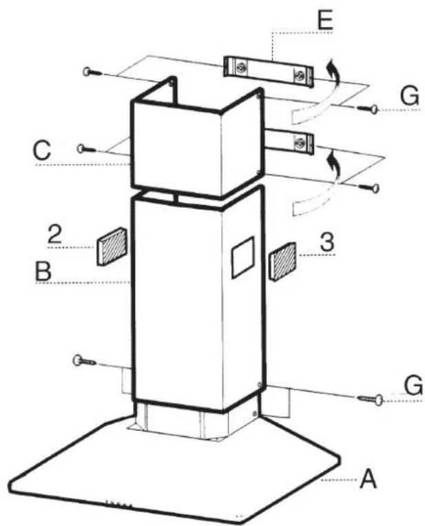
FIGURE 10
FOR DUCTLESS INSTALLATIONS
Fit the LEFT AND RIGHT VENT GRIDS (2 and 3) into the LOWER CHIMNEY DUCTLESS holes, making sure that the directional symbols are towards the top and front of the hood and that they connect snugly to the DIVERTER EXTENSION HORIZONTAL pieces.
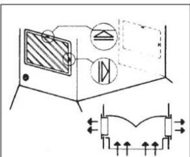
FIGURE 11
FOR ALL INSTALLATIONS
- Install the grease filters using two hands by first pulling and turning the knob to the left so that the locking lever does not protrude from the filter (as in FIGURE 12). Insert the opposite end of the filter into the retaining channel. Insert the knob end next, then turn knob to the right to lock the filter into place.
- Turn the power supply on. Turn on blower and lights. If the rangehood does not operate, check that the circuit breaker is not tripped or the house fuse blown. If the unit still does not operate, disconnect the power supply and check that the wiring connections have been made properly.
- This rangehood uses 20 watt halogen lamps.
USE AND CARE INFORMATION
This rangehood system is designed to remove smoke, cooking vapors and odors from the cooktop area.
For Best Results
Start the rangehood several minutes before cooking to develop proper airflow. Allow the unit to operate for several minutes after cooking is complete to clear all smoke and odors from the kitchen.
Rangehood Control Panel and Hood Operation
The control panel is located on the front edge of the rangehood canopy. The position and function of each control button are indicated in FIGURE 13.
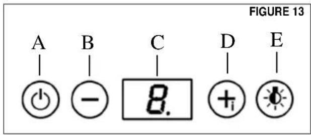
Button A. Press button to turn fan on / off. Current speed is displayed in C display (1, 2, 3)
Button B. Press to reduce fan speed to as low as speed 1, display C shows the speed selected (1, 2, 3). Hold for 3 seconds to turn on 30 minute delay feature which runs the hood for 30 minutes and automatically shuts the hood off. Current speed on 30 minute delay is shown in C display with a blinking light to indicate 30 minute mode. Shut off the 30 minute mode by holding down the button for 3 seconds
Button C. LED single digit readout display screen
Button D. Press button to increase fan speed up to speed 3. Hold for 3 seconds to activate intensive speed mode which operates hood on highest speed for 10 minutes and then returns to previous speed setting. Display C indicates intensive speed with an "H" and blinking light. Shut off the intensive speed mode by holding down the button for 3 seconds
Button E. Press the button to turn on and off lighting. Press once to turn the dimmer light on, press twice to turn the normal light setting on, and press again to turn off the lighting.
Cleaning
The stainless steel grease filters should be cleaned frequently in hot detergent solution or washed in the dishwasher. Stainless steel cleaner should be used on stainless rangehoods. Abrasives and scouring agents can scratch stainless steel finishes and should not be used to clean finished surfaces.
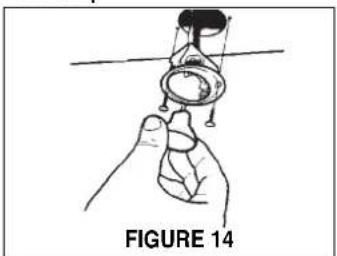
Replacing the Lamps
Before attempting to replace the lamps, make sure that the light switch is turned off. Remove the 2 screws (as indicated in FIGURE 14) that hold the light support and gently pull the support down from the hood. Remove the lamp from the light support and replace with new lamp. Replace the light support and fix it into place with the 2 screws.
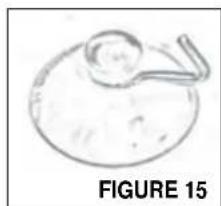
An alternative method to replace the lamps is to use a 1 1/4" suction cup (FIGURE 15). Attach the suction cup to the bulb and pull firmly down on the bulb and replace with a new lamp.
natural_image
Illustration of a hand holding a small object above a horizontal line, labeled 'FIGURE 14' (no text or symbols on the diagram itself)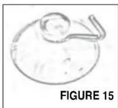
natural_image
Simple line drawing of a circular object with a curved handle, labeled 'FIGURE 15' (no text or symbols on the object itself)Version 07/11 - Page 9
FABER
FABER CONSUMER WARRANTY & SERVICE
All Faber products are warranted against any defect in materials or workmanship for the original purchaser for a period of 1 year from the date of original purchase (requires proof of purchase). This warranty covers labor and replacement parts. Faber, at its option, may repair or replace the product or components necessary to restore the product to good working condition. To obtain warranty service, contact the dealer from whom you purchased the range hood, or the local Faber distributor. If you cannot identify a local Faber distributor, contact us at (508) 358-5353 for the name of a distributor in your area.
The following is not covered by Faber's warranty:
- Service calls to correct the installation of your range hood, to instruct you how to use your range hood, to replace or repair house fuses or to correct house wiring or plumbing.
- Service calls to repair or replace range hood light bulbs, fuses or filters. Those consumable parts are excluded from warranty coverage.
- Repairs when your range hood is used for other than normal, single-family household use.
- Damage resulting from accident, alteration, misuse, abuse, fire, flood, acts of God, improper installation, installation not in accordance with electrical or plumbing codes or Faber documentation, or use of products not approved by Faber.
- Replacement parts or repair labor costs for units operated outside the United States or Canada, including any non-UL or C-UL approved Faber range hoods.
- Repairs to the hood resulting from unauthorized modifications made to the range hood.
- Expenses for travel and transportation for product service in remote locations and pickup and delivery charges. Faber range hoods should be serviced in the home.
THIS WARRANTY DOES NOT ALLOW RECOVERY OF INCIDENTAL OR CONSEQUENTIAL DAMAGES, INCLUDING, WITHOUT LIMITATION, DIRECT, INDIRECT, INCIDENTAL, SPECIAL OR CONSEQUENTIAL DAMAGES, PERSONAL INJURY/WRONGFUL DEATH OR LOST PROFITS FABER WARRANTY IS LIMITED TO THE ABOVE CONDITIONS AND TO THE WARRANTY PERIOD SPECIFIED HEREIN AND IS EXCLUSIVE. EXCEPT AS EXPRESSLY SPECIFIED IN THIS AGREEMENT, FABER DISCLAIMS ALL EXPRESS OR IMPLIED CONDITIONS, REPRESENTATIONS, AND WARRANTIES INCLUDING, WITHOUT LIMITATION, ANY IMPLIED WARRANTIES OF MERCHANTABILITY OR FITNESS FOR A PARTICULAR PURPOSE.
This warranty gives you specific legal rights that may vary from state to state.
Model#:
Serial #:
January 4, 2016
OUTILS NÉCESSAIRES À L'INSTALLATION
FIGURE 4A INSTALLATIONS AVEC CONDUIT
other
| Section | Min (x) | Max (y) | | -------- | ------- | ------- | | couvercle cheminée supérieure | 10 | 16 | | couvercle cheminée inférieure sans conduit | 22 | 3 | | Hotte | 3 | 22 | | x = distance entre la hotte et la table de cuisson | -24 | -30 | | min & max hauteurs de plafond | 24 | 26 | | x = 28 | 28 | 30 | | min | 7 | 8 | | min | 8 | 9 | | min | 8 | 11 | | min | 11 | 3/8 | | min | 11 | 3/8 | | min | 11 | 5/8 | | min | 11 | 3/8 | | min | 11 | 5/8 | | min | 11 | 3/8 | | min | 11 | 5/8 | | min | 11 | 3/8 | | min | 11 | 5/8 | | min | 11 | 3/8 | | min | 11 | 5/8 | | | x = distance entre la hotte et la table de cuisson | -24 | -30 | | min - 24 po, suggested max - 30 po | -24 | -30 | | x = distance entre la hotte et la table de cuisson | -24 | -30 | | x = distance entre la hotte et la table de cuisson | -24 | -30 | | x = distance entre la hotte et la table de cuisson | -24 | -30 | | x = distance entre la hotte et la table de cuisson | -24 | -30 | | x = distance entre la hotte et la table de cuisson | -24 | -3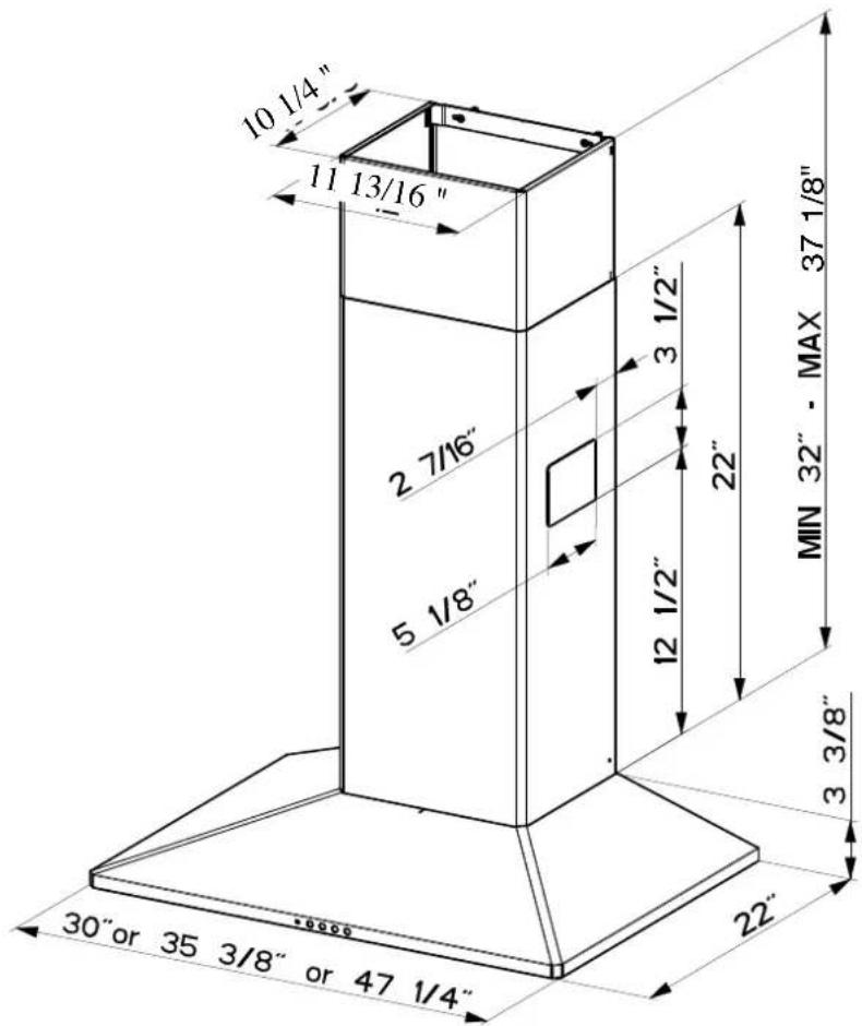
PRÉPARATION DU MUR
natural_image
Illustration of a hand holding a folded garment with a curved arrow indicating rotation (no text or symbols)- CHEMINÉE INFÉRIEURE AVEC TROUS D'ECHAPPEMENT D'AIR
- VENT GRID GAUCHE
- VENT GRID DROIT
- DIVERTER EXTENSION HORIZONTAL (DEUX)
- DUCTLESS DIVERTER
- FILTRE CHARBON
FIGURE 8
INSTALLATIONS SANS CONDUIT
INSTALLATIONS SANS CONDUIT
POUR TOUT LES INSTALLATIONS
natural_image
Illustration of a hand holding a mechanical component with a suspended ring, labeled 'FIGURE 14' (no text or symbols on the diagram itself)