
FLEX24SS300 - Basket FABER - Free user manual and instructions
Find the device manual for free FLEX24SS300 FABER in PDF.

| Product Type | Under-cabinet range hood |
| Brand | Faber |
| Model | FLEX24SS300 |
| Dimensions (W × D × H) | 598 × 500 × 150 mm (estimated) |
| Weight | 8 kg (estimated) |
| Power supply | 120 V ~ 60 Hz, 15 A, dedicated circuit |
| Motor power | 200 W (estimated) |
| Maximum airflow | 500 CFM (≈ 850 m³/h, estimated) |
| Maximum noise level | 65 dB (estimated) |
| Controls | Mechanical switches: 3 speeds + light |
| Lighting | 2 self-ballasted E12 LED bulbs |
| Filters | Washable metal grease filters (every 2 months); optional activated charcoal filter (SKU FILTER7) to replace every 4 months |
| Ventilation modes | External exhaust (rear or top) or recirculation |
| Material | Brushed stainless steel |
| Special features | Automatic operation when panel opens/closes; customizable front strip |
| Safety | Grounding required; auto shut-off? (not specified); complies with electrical codes |
| Maintenance and cleaning | Clean metal filters in dishwasher or hot water; clean stainless steel with appropriate cleaner |
| Spare parts and repairability | LED bulbs, grease filters, charcoal filters (FILTER7), front strip |
| Warranty | 2-year limited (parts and labor) |
Frequently Asked Questions - FLEX24SS300 FABER
User questions about FLEX24SS300 FABER
0 question about this device. Answer the ones you know or ask your own.
Ask a new question about this device
Download the instructions for your Basket in PDF format for free! Find your manual FLEX24SS300 - FABER and take your electronic device back in hand. On this page are published all the documents necessary for the use of your device. FLEX24SS300 by FABER.
USER MANUAL FLEX24SS300 FABER
natural_image
Technical line drawing of a mechanical housing or enclosure with mounting base and internal components (no text or symbols)FABER
FLEXA
Installation Instructions Use and Care Information
Important safety instructions 3
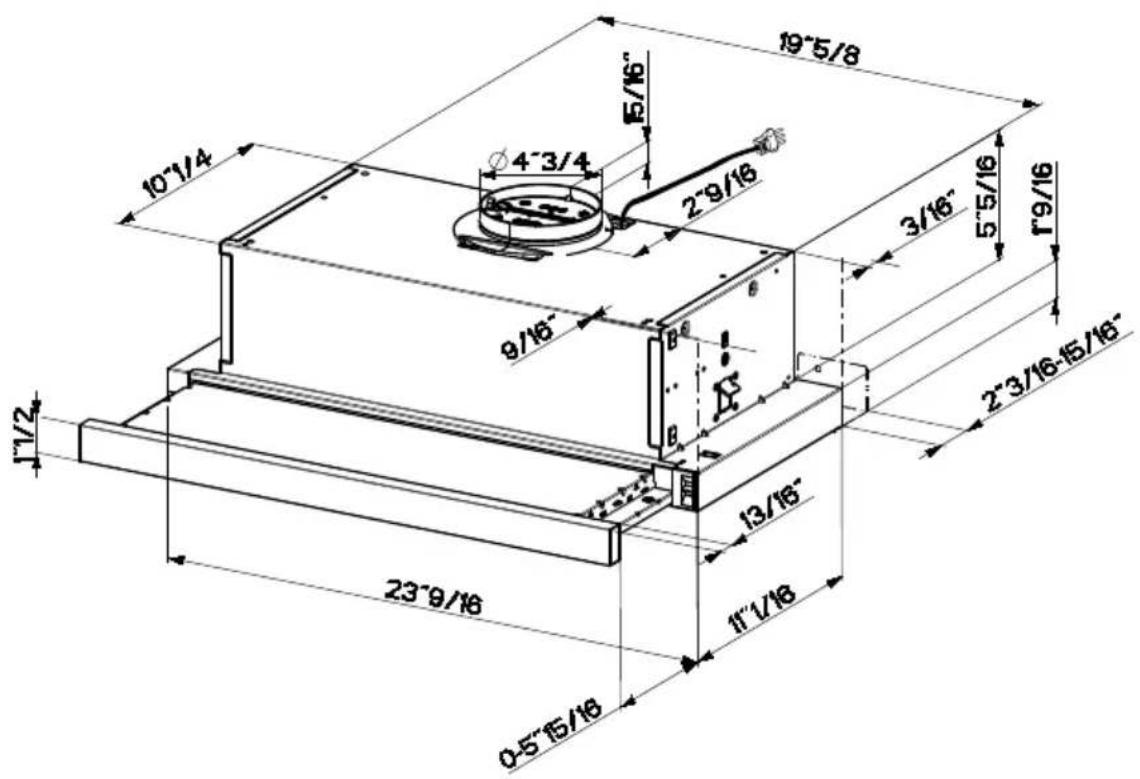
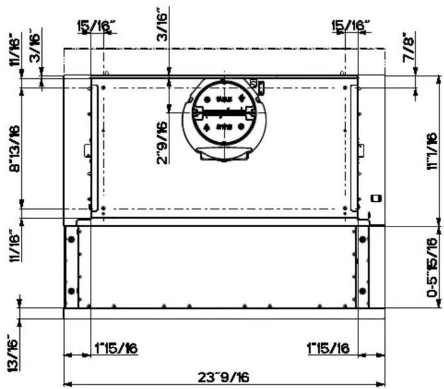
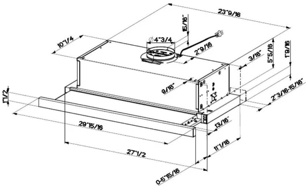
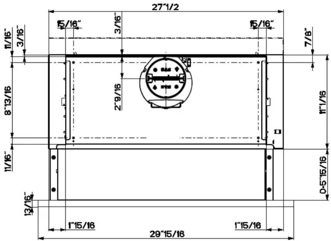
Range hood dimensions 6
Installation height requirements 8
Parts 9
Tools needed 11
Venting method 12
Preparing the cabinet 13
Install the rear trim strip 16
Choosing venting method 17
Attach venting: option 1 - rear or top vented 18
Attach venting: option 2 - non ducted recirculating 19
Connecting house power 20
Operating the controls 22
Cleaning stainless steel 23
Caring for filters 23
Replacing the activated charcoal filter 24
Replacing bulbs 25
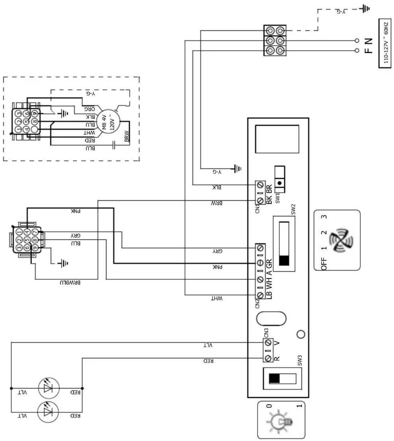
Wiring diagram 26
Warranty 27
READ AND SAVE THESE INSTRUCTIONS BEFORE YOU START INSTALLING THIS Range Hood
WARNING: - TO REDUCE THE RISK OF A RANGE TOP GREASE FIRE:
a) Never leave surface units unattended at high settings. Boilovers cause smoking and greasy spillovers that may ignite. Heat oils slowly on low or medium setting.
b) Always turn hood ON when cooking at high heat or when flambeing food (i.e. Crepes Suzette, Cherries Jubilee, Peppercorn Beef Flambé).
c) Clean ventilating fans frequently. Grease should not be allowed to accumulate on fan or filter.
d) Use proper pan size. Always use cookware appropriate for the size of the surface element.
WARNING: - TO REDUCE THE RISK OF INJURY TO PERSONS IN THE EVENT OF A RANGE TOP GREASE FIRE, OBSERVE THE FOLLOWING*:
a) SMOTHER FLAMES with a close-fitting lid, cookie sheet, or metal tray, then turn off the burner. BE CAREFUL TO PREVENT BURNS. If the flames do not go out immediately EVACUATE AND CALL THE FIRE DEPARTMENT.
b) NEVER PICK UP A FLAMING PAN - You may be burned.
c) DO NOT USE WATER, including wet dishcloths or towels - a violent steam explosion will result.
d) Use an extinguisher ONLY if:
-
You know you have a Class ABC extinguisher, and you already know how to operate it.
-
The fire is small and contained in the area where it started.
-
The fire department is being called.
-
You can fight the fire with your back to an exit.
* Based on "Kitchen Firesafety Tips" published by NFPA
WARNING - TO REDUCE THE RISK OF FIRE OR ELECTRIC SHOCK, do not use this fan with any solid-state speed control device.
WARNING - TO REDUCE THE RISK OF FIRE, ELECTRICAL SHOCK, OR INJURY TO PERSONS, OBSERVE THE FOLLOWING:
- Use this unit only in the manner intended by the manufacturer. If you have any questions, contact the manufacturer.
- Before servicing or cleaning unit, switch power off at service panel and lock the service disconnecting means to prevent power from being switched on accidentally. When the service disconnecting means cannot be locked, securely fasten a prominent warning device, such as a tag, to the service panel.
CAUTION: For General Ventilating Use Only. Do Not Use To Exhaust Hazardous or Explosive Materials and Vapors.
WARNING - TO REDUCE THE RISK OF FIRE, ELECTRICAL SHOCK, OR INJURY TO PERSONS, OBSERVE THE FOLLOWING:
- Installation Work And Electrical Wiring Must Be Done By Qualified Person(s) In Accordance With All Applicable Codes And Standards, Including Fire-Rated Construction.
-
Sufficient air is needed for proper combustion and exhausting of gases through the flue (chimney) of fuel burning equipment to prevent backdrafting. Follow the heating equipment manufacturer's guideline and safety standards such as those published by the National Fire Protection Association (NFPA), and the American Society for Heating, Refrigeration and Air Conditioning Engineers (ASHRAE), and the local code authorities.
-
When cutting or drilling into wall or ceiling, do not damage electrical wiring and other hidden utilities.
- Ducted fans must always be vented to the outdoors.
ALL WALL AND FLOOR OPENINGS WHERE THE Range Hood IS INSTALLED MUST BE SEALED.
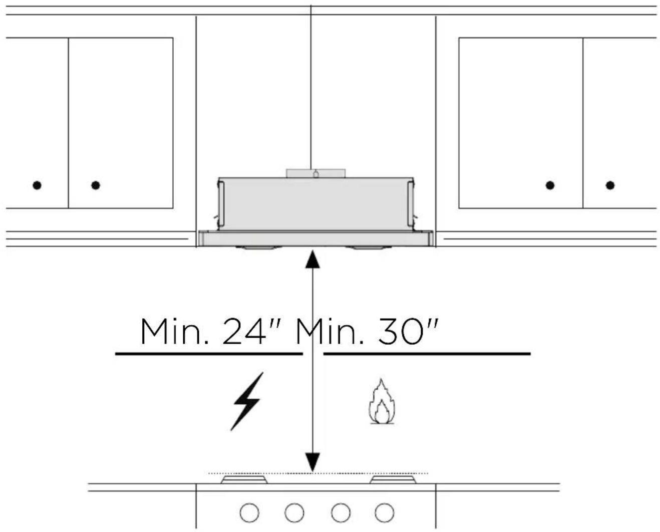
This Range Hood requires at least 24" of clearance between the bottom of the Range Hood and the cooking surface or countertop. This hood has been approved by UL at this distance from the cooktop.
This minimum clearance may be higher depending on local building codes. For gas cooktops and combination ranges, a minimum of 30" is recommended and may be required.
Overhead cabinets on both sides of this unit must be a minimum of 18" above the cooking surface or countertop. Consult the cooktop or range installation instructions given by the manufacturer before making any cutouts.
MOBILE HOME INSTALLATION The installation of this Range Hood must conform to the Manufactured Home Construction and Safety Standards, Title 24 CFR, Part 3280 (formerly Federal Standard for Mobile Home Construction and Safety, Title 24, HUD, Part 280). See Electrical Requirements"
VENTING REQUIREMENTS
Determine which venting method is best for your application. Ductwork can extend either through the wall or the roof.
The length of the ductwork and the number of elbows should be kept to a minimum to provide efficient performance. The size of the ductwork should be uniform. Do not install two elbows together. Use duct tape to seal all joints in the ductwork system. Use caulking to seal exterior wall or floor opening around the cap.
Flexible ductwork is not recommended. Flexible ductwork creates back pressure and air turbulence that greatly reduces performance.
Make sure there is proper clearance within the wall or floor for exhaust duct before making cutouts. Do not cut a joist or stud unless absolutely necessary. If a joist or stud must be cut, then a supporting frame must be constructed.
WARNING - To Reduce The Risk Of Fire, Use Only Metal Ductwork.
CAUTION - To reduce risk of fire and to properly exhaust air, be sure to duct air outside - Do not vent exhaust air into spaces within walls or ceilings or into attics, crawl spaces, or garages.
WARNING: To Reduce The Risk Of Fire, Electric Shock Or Injury To Persons, Do Not Use Replacement Parts That Have Not Been Recommended By The Manufacturer (e.g. Parts Made At Home Using A 3D Printer).
WARNING
- Venting system MUST terminate outside the home.
- DO NOT terminate the ductwork in an attic or other enclosed space.
- DO NOT use 4" laundry-type wall caps.
- Flexible-type ductwork is not recommended.
- DO NOT obstruct the flow of combustion and ventilation air.
- Failure to follow venting requirements may result in a fire.
Cold Weather installations
An additional back draft damper should be installed to minimize backward cold air flow and a nonmetallic thermal break should be installed to minimize conduction of outside temperatures as part of the vent system. The damper should be on the cold air side of the thermal break. The break should be as close as possible to where the vent system enters the heated portion of the house.
ELECTRICAL REQUIREMENTS
A 120 volt, 60 Hz AC-only electrical supply is required on a separate 15 amp fused circuit. A time-delay fuse or circuit breaker is recommended. The fuse must be sized per local codes in accordance with the electrical rating of this unit as specified on the serial/rating plate located inside the unit near the field wiring compartment.
WARNING
• Electrical ground is required on this Range Hood.
- If cold water pipe is interrupted by plastic, nonmetallic gaskets or other materials, DO NOT use for grounding.
• DO NOT ground to a gas pipe.
- DO NOT have a fuse in the neutral or grounding circuit. A fuse in the neutral or grounding circuit could result in electrical shock.
- Check with a qualified electrician if you are in doubt as to whether the Range Hood is properly grounded.
- Failure to follow electrical requirements may result in a fire.
State of California Proposition 65 Warning (US only)
WARNING
This product contains chemicals known to the State of California to cause cancer and birth defects or other reproductive harm.
For more information go to www.P65Warnings.ca.gov
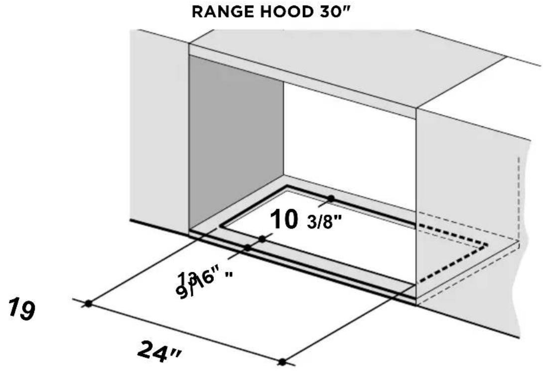
RANGE HOOD 24"
RANGE HOOD 30"
MIN. 24" OVER ELECTRIC / MIN. 30" OVER GAS
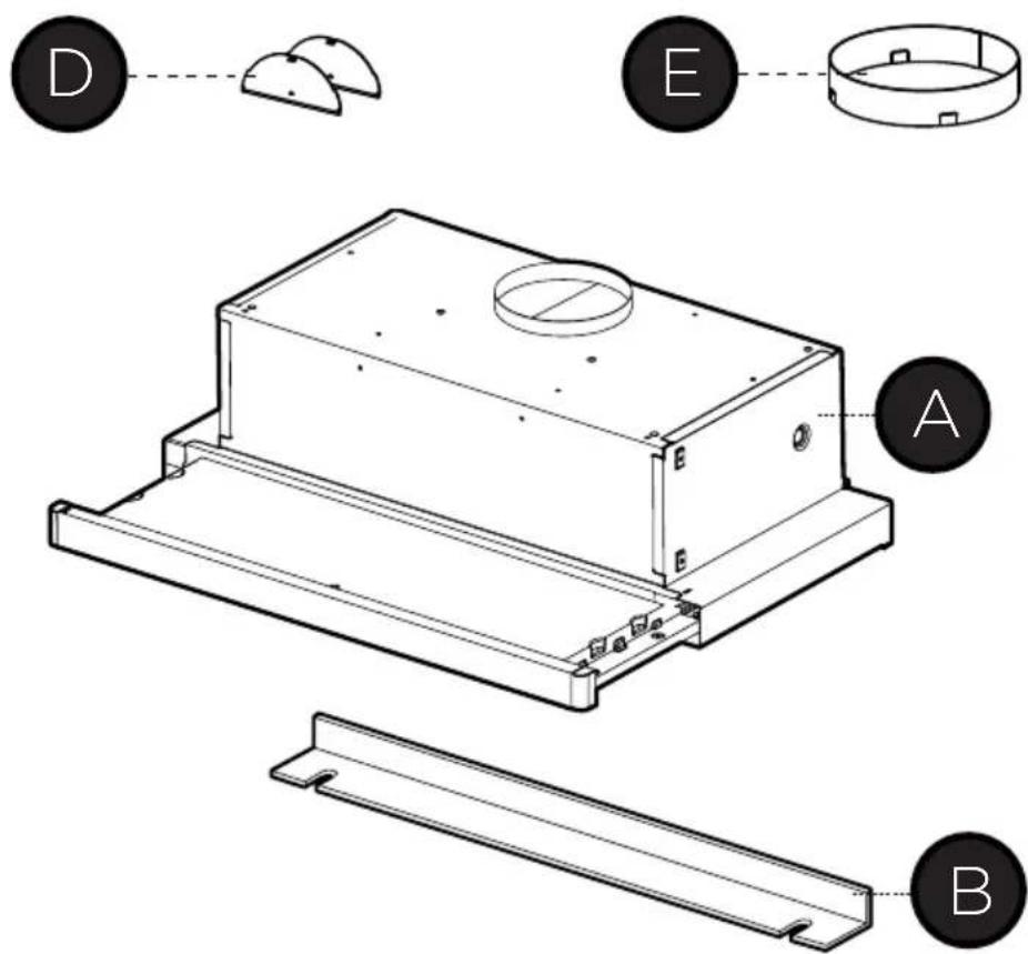
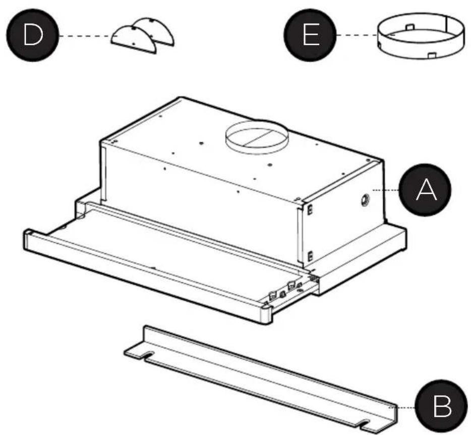
PARTS INCLUDED
| REF. | PART | QTY |
| A | Hood body 1 | |
| B | Rear Trim Strip 1 | |
| D | Damper flaps 2 | |
| E | Metal ring 1 |
| REF | PART | ||
| F | Pozi Screws (3/16" x 1/2") | 2 | |
PARTS NEEDED
| PART | |
| 5" Round Metal Ductwork |   |
| Foil tape |  |
ACCESSORIES AVAILABLE
| ACCESSORY SKU# | |
| Activated Charcoal Filter Kit #FILTER7 |
TOOLS NEEDED
| TOOL | |
| Tape Measure |  |
| Pencil |  |
| Electric Drill with 5/16" Drill Bit |  |
| Phillips Screwdriver |  |
| Pozi Screwdriver |  |
| Metal sheers |  |
| Work gloves |  |

Option 1: REAR OR TOP VENTED
Option 2: RECIRCULATING
Requires purchase of Activated Charcoal Accessory kit.
natural_image
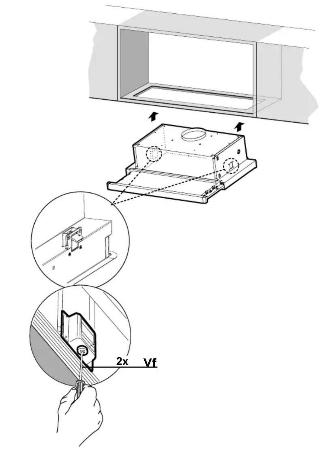
Pure mechanical diagram showing a piston-cranked mechanism with arrows indicating motion, no text or symbols present.ATTACHING THE HOOD TO THE CABINET
1 The Hood can be installed directly on the underside of the cabinet.
2 If the cabinet bottom is recessed, wood blocks need to be installed to insure proper alignment with the cabinet bottom.
Wood blocks should be flush or recessed 1/16" to 1/8" within the cabinet bottom as shown.
3) Create a cut out in the bottom of the cabinet as shown in the illustration.
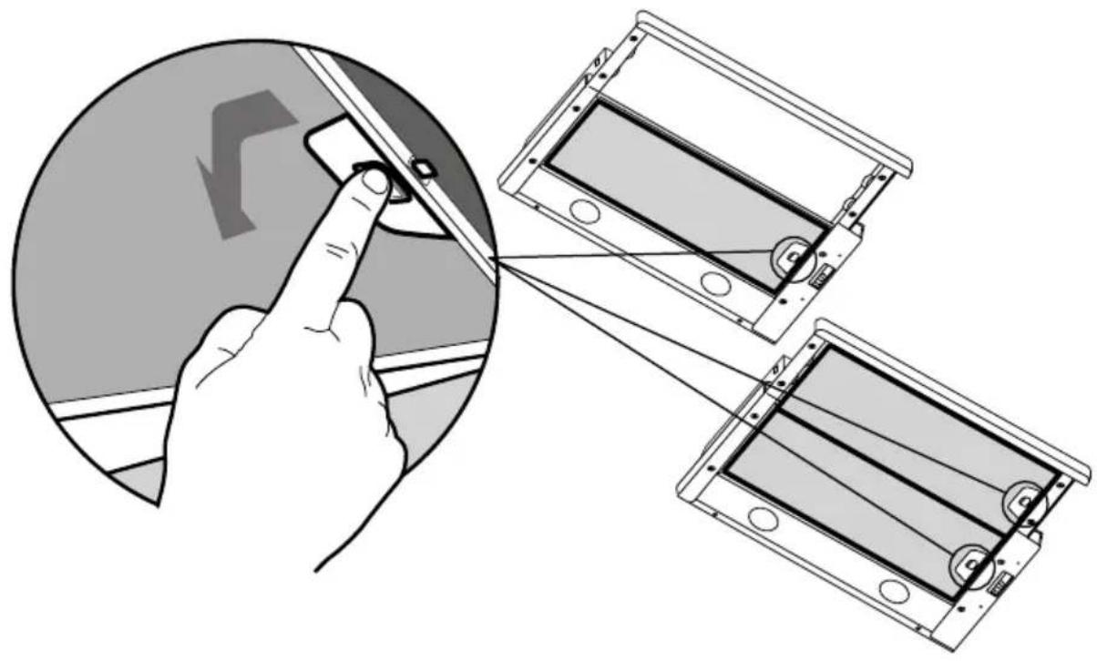
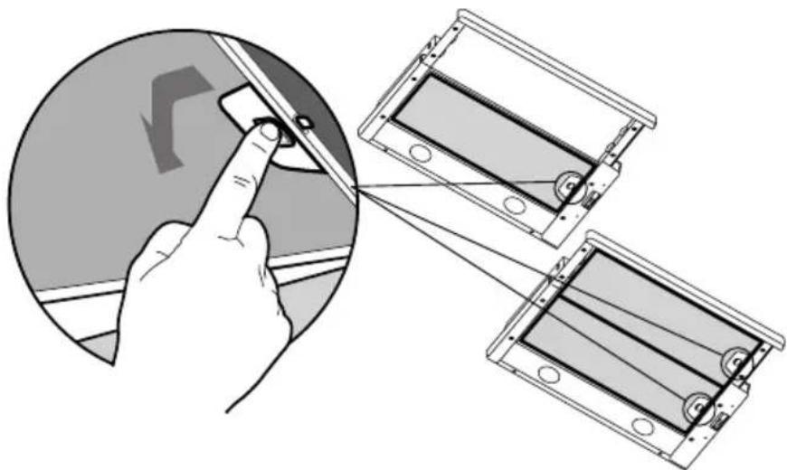
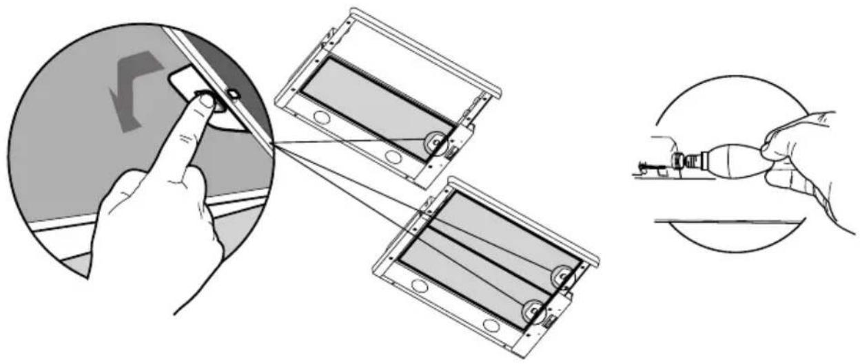
4 Remove the grease filters by pushing the release tab towards the side of hood.
natural_image
Illustration showing a hand interacting with a device, with three views of the device (no text or symbols present)
Insert the hood in the cut out until the side installation clips snap into place. Lock the hood into position by tightening the 2 screws Vf from underneath.
| Phillips Screwdriver |

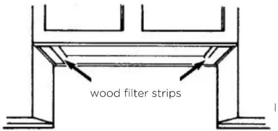
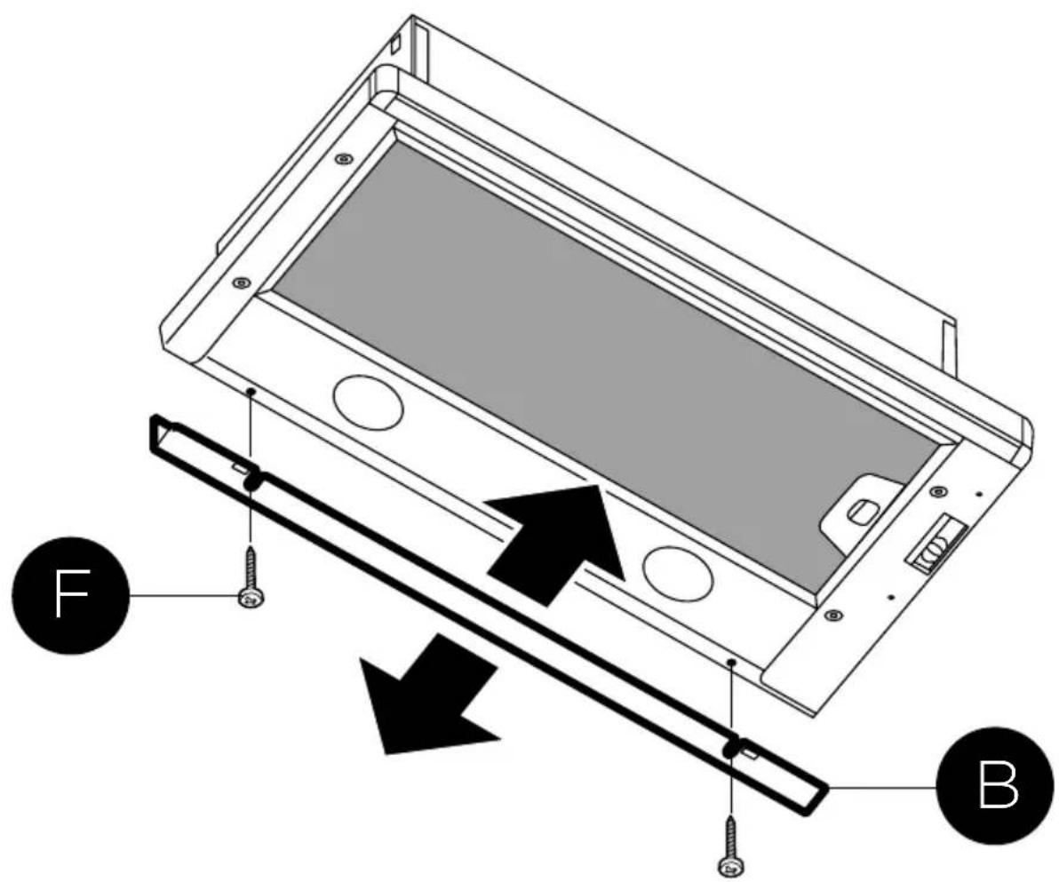
A rear trim strip B is included to cover the underside of any remaining exposed cabinet. Attach the vinyl strip to the bottom of the back of the rangehood with the two screws F provided.
| Pozi Screwdriver |
5
Option 1: REAR OR TOP VENTED
Go to Pg.17
Option 2: RECIRCULATING
natural_image
Pure mechanical diagram showing a piston-cranked mechanism with upward force arrows and motion indicators (no text or symbols)Requires purchase of Activated Charcoal Accessory kit.
Go to Pg.18
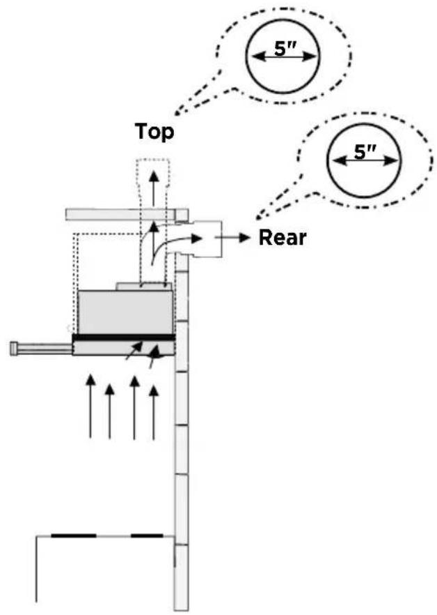
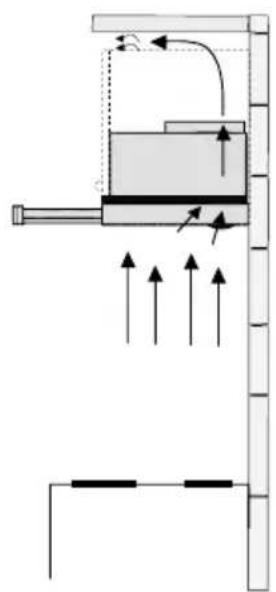
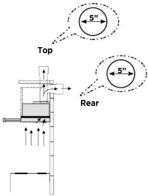
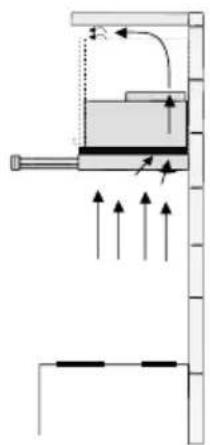
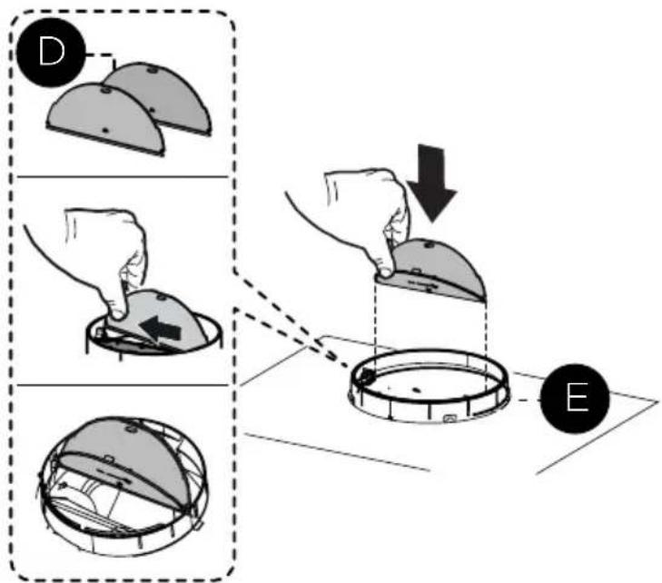
ATTACH VENTING: OPTION 1 - REAR OR TOP VENTED
1
Install the Metal damper ring E included with the Hood. Then install the damper flaps D by snapping the tabs into place inside the top of the hood before connecting ductwork.
2
Install Roof or Wall Cap purchased separately. Connect the 5" metal ductwork to the Roof or Wall Cap and then attach ductwork. Seal with foil tape.
natural_image
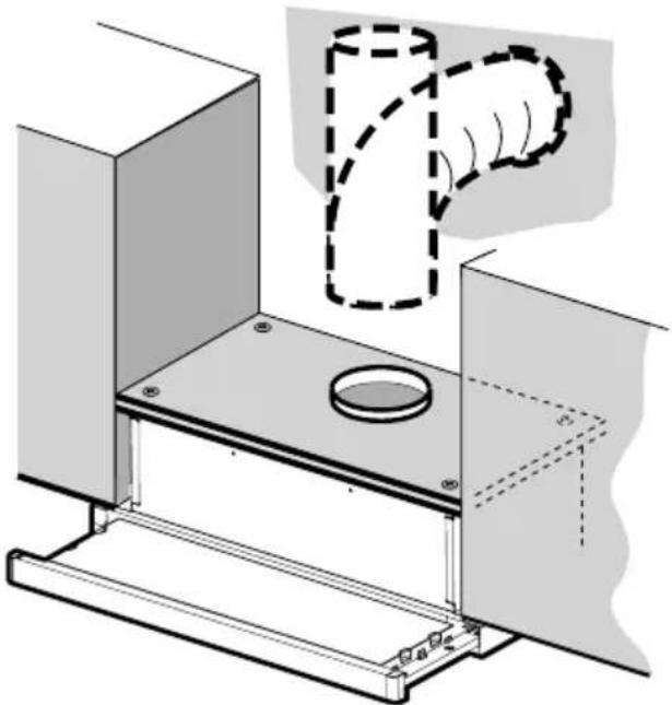
Technical illustration of a mechanical assembly with a hand gesture overlay (no text or symbols)ATTACH VENTING: OPTION 2 - NON DUCTED RECIRCULATING

For Non-Ducted Recirculation venting route the ductwork to a location above the hood where the discharge is vented back into the room.
Require purchase locally the Recirculation Vent Grill C to cover the opening and secure the grill with the 2 screws G not provided.
A straight 5" round duct that is at least 15" in length should be used to lead air from the top of the hood exhaust outlet to the exit of the cabinet above.
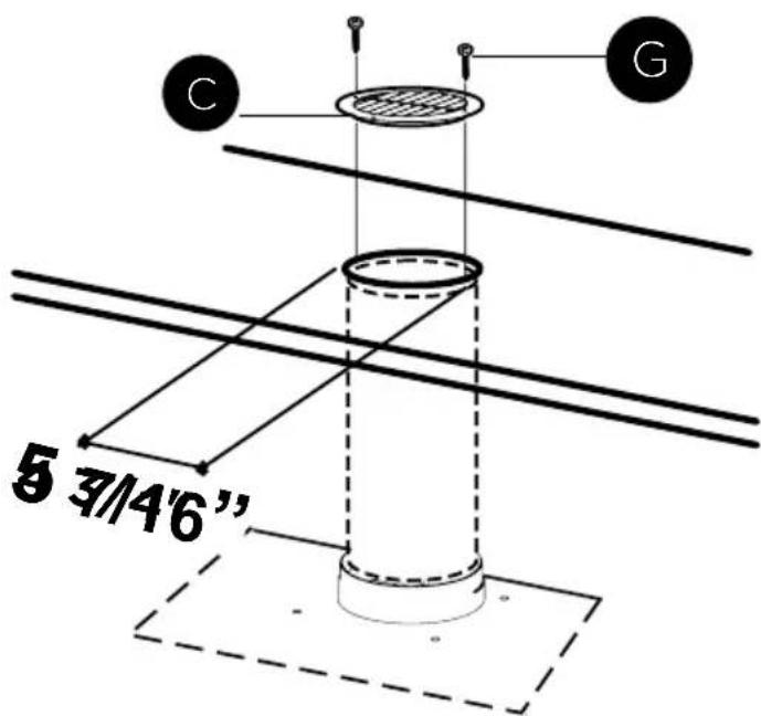
Required Activated Charcoal Filter Accessory - sku # - FILTER7
6
ELECTRICAL INSTALLATION WITH CONNECTION CABLE
GROUNDING INSTRUCTIONS This appliance must be grounded. In the event of an electrical short circuit, grounding reduces the risk of electric shock by providing an escape wire for the electric current. This appliance is equipped with a cord having a grounding wire with a grounding plug. The plug must be plugged into an outlet that is properly installed and grounded.
WARNING - Improper grounding can result in a risk of electric shock.
Consult a qualified electrician if the grounding instructions are not completely understood, or if doubt exists as to whether the appliance is properly grounded. Do not use an extension cord. If the power supply cord is too short, have a qualified electrician install an outlet near the appliance.
The power cord shall be accessible for inspection after installation.
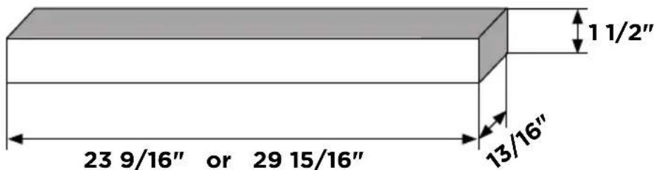
CUSTOM FRONT TRIM OPTION
This hood comes with a stainless front trim installed. To replace and customize this panel, remove grease filters and the three Phillips screws located behind the strip. If necessary, the front strip can be adjusted by loosening the three Phillips screws and sliding the strip up or down.
Tighten screws when you have the strip properly placed.
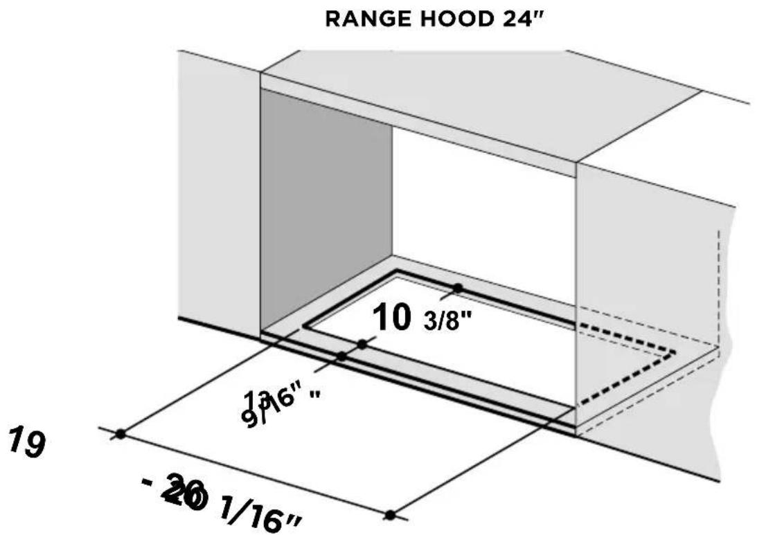
For a custom front trim, a local cabinet shop can make a strip to match your cabinets. The front strip dimensions are given in the illustration.
7
FOR NON-DUCTED RECIRCULATION OPTION
natural_image
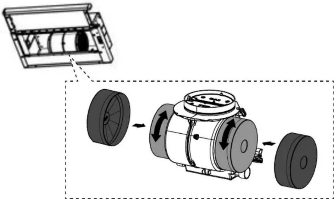
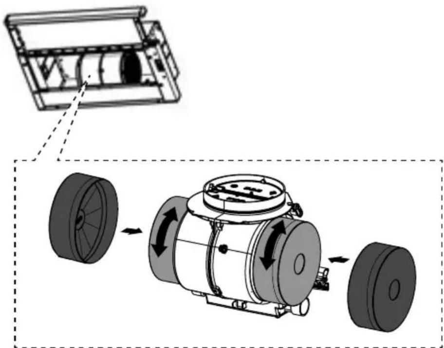
Diagram of a mechanical device showing internal components and motion arrows, with no visible text or symbols.Attach each charcoal filter to the black grid on each side of the blower. Press the charcoal filter tightly to the black grid on the blower side and rotate the filter clockwise (towards the front of the hood) until it locks into place. Turn counterclockwise (towards the back of the hood) to remove (for more details see paragraph Changing and Inserting the Charcoal Filter)
Required Activated Charcoal Filter Accessory - sku # - FILTER7
8
Reinstall the grease filters removed previously.

natural_image
Illustration showing a hand holding a smartphone with a magnified inset of its screen and two views of the device (no text or symbols present)Start the Range Hood several minutes before cooking to develop proper airflow. Allow the Range Hood to operate for several minutes after cooking is complete to clear all smoke and odors from the kitchen.

| All controls are located on the right side of the rangehood | ||
| L | Light The On/Off switch for the light is located behind the front trim.Moving the switch to the 1 Position turns the light On.Moving the switch to the 0 Position turns the light Off. | |
| M-V | Motor/Speed | M-V shows the speed control switch for the blower.Moving the switch to the 1 Position turns the blower on LOW.Moving the switch to the 2 Position turns the blower on MEDIUM.Moving the switch to the 3 Position turns the blower on HIGH.Moving the switch to the 0 Position turns the blower off. |
| Automatic OperationAs long as the blower and light switches are on, the blower and light will automatically operate when the visor is opened and shut off when the visor is closed. | ||
Cleaning Exterior surfaces:
Please note, abrasives and scouring agents can scratch range hood finishes and should not be used to clean finished surfaces.
Stainless Steel finish cleaning instructions:
Clean exterior surfaces with a commercially available stainless steel cleaner.
CARING FOR FILTERS
CLEANING METAL GREASE FILTERS
The metal grease filters can be cleaned in hot detergent solution or washed in the dishwasher. They should be cleaned every 2 months use, or more frequently if use is particularly heavy.
- Pull out the sliding suction panel.
- Remove the grease filters by pushing the release tab towards the side of hood.
- Wash the filter without bending it, leave it to dry thoroughly before replacing (if the surface of the filter changes color over time, this will have absolutely no effect on its efficiency).
- Replace, taking care to ensure that the handle faces forward.
- Cleaning in dishwasher may dull the finish of the metal grease filter.
- Close the sliding suction panel.
- Completely dry the filters before installing back into the hood. No water should be trapped in the filter before reinstalling.
natural_image
Diagram showing a hand using a tool to inspect a car front panel, with two views of the panel being tilted (no text or symbols present)REPLACING THE ACTIVATED CHARCOAL FILTER
The Activated Charcoal Filters (FILTER7) are not washable and cannot be regenerated, and must be replaced approximately every 4 months of operation, or more frequently with heavy usage.
- Pull out the sliding suction panel.
- Remove the grease filters by pushing the release tab towards the side of hood.
- Remove the saturated carbon filter by releasing the fixing hooks.
- Fit the new filter by hooking it into its seating.
- Replace the filter, taking care to ensure that the handle faces forwards.
- Close the sliding suction panel.
CAUTION: When used in recirculation mode, to Reduce the Risk of Fire and Shock use only conversion kit Model FILTER7.
- Pull out the sliding suction panel.
- Remove the filter.
- Replace the lamp with a new one of the same type.
- Replace the grease filters.
natural_image
Illustration showing a hand using a tool to adjust or install a device, with no visible text or symbols.E12 self-ballasted led lamps – listed in accordance with ul 1993/nmxj-578/1-ance/ csa c22.2 No. 1993


Franke Home Solutions Warranty for Franke and Faber Branded Product Effective March 1, 2022
In the United States, Canada and Latin America, Franke warrants the Faber branded products from manufacturing defects in material and workmanship when purchased from a Franke or Faber Authorized Retailer pursuant to product-specific warranties detailed herein (each, a "Warranty" and collectively, the "Warranties"). The products must be properly installed, per Franke's installation instructions, in their original installation, and used in normal indoor residential kitchen applications. Any products or components which have been modified or altered from their original intended condition will void the Warranty. The Franke Warranties for Faber branded products are limited to the original purchaser and are non-transferrable. These Warranties do not include products purchased from non-Authorized Retailers, products that are obsolete or discontinued, or products that were previous display models. All issues with installed products are considered warranty claims and not subject to the Return Policy. Franke reserves the right to inspect any Franke / Faber product reported to be defective pursuant to a Warranty claim and the original installation prior to providing a replacement product and/or component. All decisions are final. In no situation shall the liability of Franke exceed the amount of the original purchase price.
The Warranties do not cover, and Franke shall not be liable for, any damage to products or components resulting from misuse or abuse, accidental damages, normal wear such as scuffs, scratches or finish reduction/fading, improper installation, abnormal usage, negligence, damage caused by improper maintenance or cleaning. Damage caused by impurities, corrosive chemicals or acts beyond Franke's control are not covered by any Warranty. Service calls to correct the installation of a range hood, instructions on how to operate a range hood, to replace or repair house fuses or to correct house wiring or plumbing are not covered by any Warranty. Service calls to repair or replace range hood light bulbs, fuses or filters and these consumable part costs are also excluded from Warranty coverage. Installation not in accordance with electrical or plumbing codes or Franke / Faber documentation are not covered by any Warranty. Replacement parts or repair labor costs for units operated outside the United States, Canada or Latin America, including any non-UL or C-UL or non-NOM approved Franke / Faber range hoods are excluded from Warranty coverage. Expenses for travel and transportation for service in remote locations and pickup and delivery charges are not covered by any Warranty. Franke / Faber range hoods should always be serviced in the home in their original installation.
Franke / Faber product replacements do not include liability for project delays. Product replacements are not guaranteed to be exact replacements. If the original product is not available at the time of the warranty claim, at Franke's option, the product replacements will be of similar size, material, and value. Any products or components which have been modified or altered, from its original intended condition will void the warranty.
The Warranties do not allow recovery of incidental or consequential damages such as loss of use, delay, property damage or other consequential damage, and Franke accepts no liability for such damages. Each Warranty is limited to the conditions set forth herein and to the applicable warranty period specified herein and is exclusive. EXCEPT FOR THE WARRANTIES SET FORTH HEREIN, FRANKE MAKES NO WARRANTY WHATSOEVER WITH RESPECT TO THE PRODUCTS, INCLUDING, BUT NOT LIMITED TO, (1) ANY WARRANTY OF MERCHANTABILITY, (2) WARRANTY OF FITNESS FOR A PARTICULAR PURPOSE, (3) WARRANTY OF TITLE, OR (4) WARRANTY AGAINST INFRINGEMENT OF INTELLECTUAL PROPERTY RIGHTS OF A THIRD PARTY, WHETHER EXPRESS OR IMPLIED BY LAW, COURSE OF DEALING, COURSE OF PERFORMANCE, USAGE OF TRADE OR OTHERWISE. LEGAL DISCLAIMER PLEASE
READ CAREFULLY. Franke Kitchen Systems LLC provides the above information to you as a public service to our customers. By accessing and using this information, you agree to the following and to comply with all applicable laws. If you do not agree with these terms and conditions, do not use this information. While we try to keep the information current, changes may have occurred since its creation. Contact your Regional Manager or Customer Service to verify information regarding Franke Kitchen Systems LLC programs and their use by you.
Franke / Faber Range Hood Limited Warranty:
Franke / Faber range hoods are warranted against any defect in materials or workmanship for the original purchaser for a period of two (2) years from the date of original purchase when used in standard residential indoor applications. This warranty covers labor and replacement parts. Franke, at its option, may repair or replace the product or components necessary to restore the product to good working condition.


This warranty supersedes all other warranties, expressed or implied. No employee, field sales representatives, or distribution persons are authorized to give any warranties on behalf of Franke Kitchen Systems, LLC
To make an installed product warranty claim please contact Franke at the provided contact information below. All warranty claims must include the following for processing:
- Proof of purchase from Franke or Faber Authorized Retailer
- Original purchaser's name, address (included city, state, zip), email address and phone number
- Franke / Faber model and serial number
- Date of installation
- Description of the defect
- Photos of the defect
In North America and Latin America:
Franke Home Solutions
Attn: Warranty Department
800 Aviation Parkway
Smyrna, TN 37167
HS-Warranty.US@Franke.com
Legal Entity:
Franke Kitchen Systems LLC
Section Page
PIÈCES INCLUDES
| RÉF | PIÈCE | ||
| F | Vis Pozi (3/16 " x 1/2 ") | 2 | |
PIÈCES NÉCESSAIRES
ACCESSOIRES DISPONIBLES
natural_image
Pure mechanical diagram showing a piston-cranked mechanism with arrows indicating motion, no text or symbols present.natural_image
Illustration showing a hand inserting a device into a device with a magnified inset (no text or symbols)
| Tournevis Phillips |
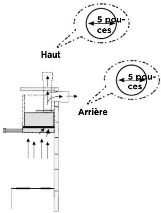
INSTALLATION DE LA BANDE DE GARNITURE ARRIÈRE

| Tournevis Pozi |
5
Option 1 : VENTILATION PAR L'ARRIÈRE OU PAR LE HAUT
natural_image
Pure mechanical diagram showing a piston-cranked mechanism with upward force arrows and motion arrows (no text or symbols)2
natural_image
Technical illustration of a mechanical assembly with a hand gesture overlay (no text or symbols)VENTILATION DE LA FIXATION : OPTION 2 - RECIRCULATION SANS CONDUIT
1
natural_image
Diagram of a mechanical assembly showing a housing, rotor, and internal components with directional arrows (no text or labels)natural_image
Diagram showing a hand interacting with a device, with three views of a mechanical component (no text or symbols present)POUR DE MEILLEURS RÉSULTATS
natural_image
Diagram showing a hand using a tool to inspect a car front panel, with two views of the panel being tilted (no text or symbols present)REPLACEMENT DU FILTRE À CHARBON ACTIF
natural_image
Illustration showing a hand using a tool to adjust or install a device, with no visible text or symbols.Franke Home Solutions
800 Aviation Parkway
Smyrna, TN 37167
HS-Warranty.US@Franke.com
Raison sociale :
Franke Kitchen Systems LLC
Sección Página
PIEZAS NECESARIAS
natural_image
Pure mechanical diagram showing a piston-cranked mechanism with arrows indicating motion, no text or symbols present.natural_image
Illustration showing a hand inserting a device into two views of a device frame (no text or symbols present)
| Destornillador Phillips |
| Destornillador Pozi |
5
natural_image
Pure mechanical diagram showing a piston-cranked mechanism with upward force arrows and motion arrows (no text or symbols)natural_image
Technical diagram of a mechanical assembly with a hand gesture overlay (no text or symbols)natural_image
Diagram of a mechanical assembly showing a housing, rotor, and internal components with directional arrows (no text or labels)natural_image
Illustration showing a hand using a tool to inspect a device, with three views of the device (no text or symbols present)natural_image
Diagram showing a hand interacting with a device panel and its three views of a mechanical component (no text or symbols present)natural_image
Illustration showing a hand using a tool to adjust or install a device, with no visible text or symbols.800 Aviation Parkway
Smyrna, TN 37167
HS-Warranty.US@Franke.com
Persona jurídica:
Franke Kitchen Systems LLC


