HDCC32512 - Surveillance Camera ABUS - Free user manual and instructions
Find the device manual for free HDCC32512 ABUS in PDF.

User questions about HDCC32512 ABUS
0 question about this device. Answer the ones you know or ask your own.
Ask a new question about this device
Download the instructions for your Surveillance Camera in PDF format for free! Find your manual HDCC32512 - ABUS and take your electronic device back in hand. On this page are published all the documents necessary for the use of your device. HDCC32512 by ABUS.
USER MANUAL HDCC32512 ABUS
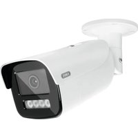
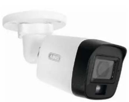
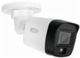
HDCC32512 / HDCC52512
HDCC52512 / HDCC55512
natural_image
Exterior view of a white and black USB security camera (no visible text or symbols)
natural_image
Close-up of a white surveillance camera with dual lens and control buttons (no visible text or symbols)natural_image
Exterior view of a white and black USB security camera (no visible text or symbols)
natural_image
Close-up of a white surveillance camera with a black circular lens and two buttons (no visible text or symbols)Bedienungsanleitung
Version 09/2025 (V1.1)
CE
text_image
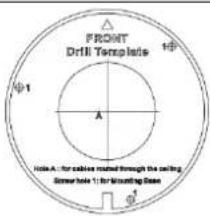
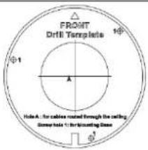
FRONT Drill Template 1 + - A Hole A : for circle moved through the ceiling. Screw Note 1 : for Mounting Base +1Bohrschablone
natural_image
Technical line drawing showing mechanical assembly and rotation of a component (no text or symbols)natural_image
Exterior view of a white and black Access Security Camera (ABSS) device with a digital display on the right (no text or symbols visible)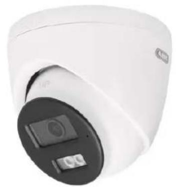
natural_image
Close-up of a white surveillance camera with a black circular lens and display screen (no visible text or symbols)Operating instructions
Version 09/2025 (V1.1)
CE
Original operating instructions in German. Keep for future use!
Introduction
Dear customer,
Thank you for purchasing this product.
The device meets the requirements of the following EU directives: EMC Directive 2014/30/EU and RoHS Directive 2011/65/EU.
To maintain this condition and ensure safe operation, you as the user must observe these operating instructions!
Read through the complete operating instructions before using the product and observe all operating and safety instructions!
All company names and product names are trademarks of their respective owners. All rights reserved.
If you have any questions, please contact your specialist installer or specialist retail partner!

Disclaimer
These operating instructions have been compiled with the utmost care. However, should you notice any omissions or inaccuracies, please let us know in writing at the address given on the back of the manual. ABUS Security Center GmbH & Co. KG accepts no liability whatsoever for technical and typographical errors and reserves the right to make changes to the product and operating instructions at any time without prior notice. ABUS Security-Center is not liable or responsible for any direct or indirect consequential damages arising in connection with the equipment, performance and use of this product. No guarantee is given for the content of this document.
Explanation of symbols
 | The symbol with the lightning bolt in the triangle is used when there is danger to the health, e.g. due to electric shock. |
 | An exclamation mark in the triangle indicates important information in these operating instructions that must be observed. |
 | This symbol can be found when you are to be given special tips and information on operation. |
Important safety instructions
 | Damage caused by failure to observe these operating instructions will invalidate the warranty. We accept no liability for consequential damage! |
 | We accept no liability for damage to property or personal injury caused by improper handling or failure to observe the safety instructions. In such cases, all warranty claims are void! |
Dear customer, the following safety and hazard information is intended not only to protect your health, but also to protect the appliance. Please read the following points carefully:
- There are no serviceable parts inside the product. Disassembly also invalidates the approval (CE) and the guarantee/warranty.
• The product can be damaged by falling from even a small height. - Mount the product in such a way that direct sunlight cannot fall on the device's image sensor. Observe the installation instructions in the corresponding chapter of these operating instructions.
- The device is designed for indoor and outdoor use (IP67).
Avoid the following adverse ambient conditions during operation:
- Moisture or excessive humidity
- Extreme cold or heat
- Direct sunlight
- Dust or flammable gases, vapors or solvents
• strong vibrations
• strong magnetic fields, such as in the vicinity of machines or loudspeakers. - The camera must not be installed on unstable surfaces.
General safety instructions:
- Do not leave the packaging material lying around carelessly! Plastic film/bags, polystyrene pieces etc. could become dangerous toys for children.
- For safety reasons, the video surveillance camera must not be given to children due to small parts that can be swallowed.
- Please do not insert any objects through the openings into the inside of the appliance
- Only use the additional devices/accessories specified by the manufacturer. Do not connect any incompatible products.
- Please observe the safety instructions and operating instructions for the other connected devices.
- Check the appliance for damage before commissioning; if this is the case, please do not operate the appliance!
- Observe the limits of the operating voltage specified in the technical data. Higher voltages can destroy the device and endanger your safety (electric shock).
Special safety instructions
- Power supply: Observe the information on the rating plate for the supply voltage and power consumption.
2. Overload
Avoid overloading mains sockets, extension cables and adapters, as this can lead to fire or electric shock.
3. Cleaning
Only clean the appliance with a damp cloth without using harsh cleaning agents.
The appliance must be disconnected from the mains.
Warnings
All safety and operating instructions must be observed before using the device for the first time!
-
Observe the following instructions to prevent damage to the mains cable and mains plug:
-
When disconnecting the appliance from the mains, do not pull on the mains cable, but grasp the plug.
-
Make sure that the power cable is as far away as possible from heating appliances to prevent the plastic sheathing from melting.
-
Follow these instructions. Failure to do so may result in an electric shock:
-
Never open the housing or the power supply unit.
- Do not insert any metal or flammable objects inside the appliance.
-
To avoid damage caused by overvoltage (e.g. thunderstorms), please use overvoltage protection.
-
Please disconnect defective appliances from the power supply immediately and inform your specialist dealer.
 | When installing in an existing video surveillance system, make sure that all devices are disconnected from the mains and low-voltage circuits. |
 | If in doubt, do not carry out the assembly, installation and wiring yourself, but leave this to a specialist. Improper and unprofessional work on the power grid or domestic installations not only poses a risk to yourself, but also to other people.Wire the installations so that the mains and low-voltage circuits always run separately and are not connected to each other at any point or cannot be connected due to a fault. |
Note on using the IR LEDs
An IR LED (infrared light-emitting diode) is not a laser, but a light-emitting diode that emits infrared light. Lasers, on the other hand, generate a coherent (synchronized in time, phase and frequency), directed beam of light,
while an IR LED has a wider light distribution.
If the distance between an IR LED and an object is small, the IR radiation can be
but still achieve a high intensity and thus have a similar effect to a laser.
Therefore, avoid pointing the camera directly at the eye at a short distance and for long periods of time.
Unpacking
Handle the appliance with the utmost care when unpacking it.

If the original packaging is damaged, check the appliance first. If the appliance is damaged, send it back with the packaging and inform the delivery service.
Table of contents
- Intended use 28
- Scope of delivery....28
2.1. Scope of delivery HDCC32512, HDCC35512 28
2.2. Scope of delivery HDCC52512, HDCC55512 28 - Features and functions....29
- Description of the camera 30
4.1. Description HDCC32512, HDCC35512 3
4.2. Description HDCC32512, HDCC35512 3 - Assembly / Installation 32
5.1. Mounting the camera 32
5.2. Alignment of the camera....33
5.3. Power supply....33
5.4. Attaching the video cable 33 - On-screen menu 35
6.1. Opening the on-screen menu (OSD) 35
6.2. Description of the on-screen menu (OSD) 35 - Maintenance and cleaning 40
7.1. Maintenance....40
7.2. Cleaning....40 - Waste disposal....40
1. Intended use
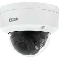
This camera is suitable for both day and night operation. It must be installed at least 2 meters from the object to be monitored. It provides video images in full HD (HDCCx2512) or 5 megapixel (HDCCx5512) resolution and the output signal is available in HD-TVI format. This enables the use of conventional coaxial cable for signal transmission. It is used for video surveillance in conjunction with a recording device. The device is designed for indoor and outdoor use. When using digital recording devices or when processing the camera signal in e.g. smartphone apps, the video signal is compressed (e.g. H.264) and may be slightly altered in the time sequence (intervals between the individual images during decompression).
2. Scope of delivery
2.1. Scope of delivery HDCC32512, HDCC35512
 |  | |
| Outdoor HD-TVI Mini Tube | Safety instructions | |
 | ||
| Drilling template | ||
2.2. Scope of delivery HDCC52512, HDCC55512
 |  |
| Outdoor HD-TVI Mini Tube | Safety instructions |
 | |||
| Drilling template | |||
3. Features and functions
• 2 or 5 megapixel resolution
- Transmission via conventional CCTV infrastructure (up to 200 meters via an RG59 cable with 2 megapixels, up to 150 meters via an RG59 cable with 5 megapixels)
• 2.8 mm fixed lens
• IR LEDs for night vision and white light LEDs
• DNR for noise-free images
• Digital WDR function to compensate for image contrasts
• Weatherproof camera housing (IP67)
- On-screen menu for camera configuration (control via DVR via coax cable)
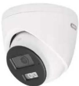
4. Description of the camera
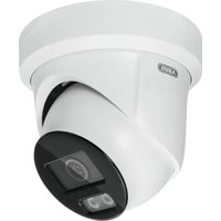
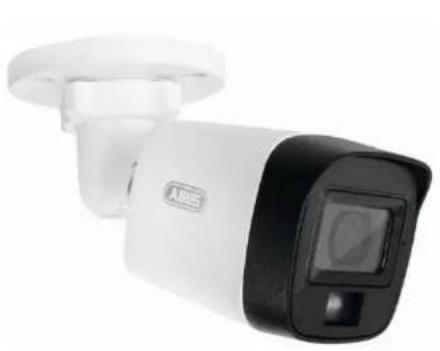
4.1. Description HDCC32512, HDCC35512
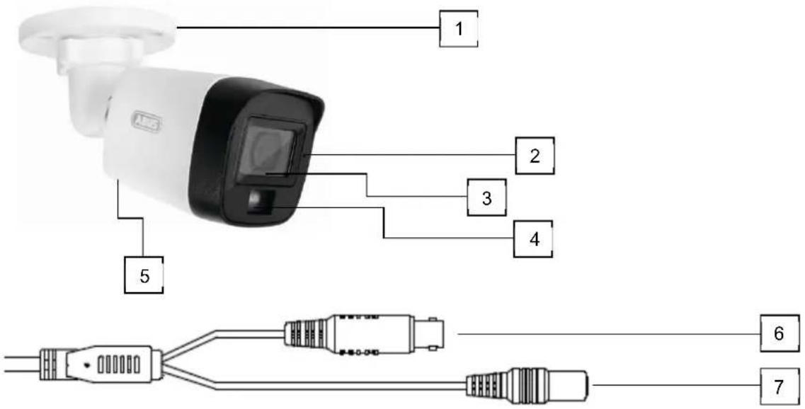
text_image
1 2 3 4 5 6 7| 1 | Camera mount with ball head (3-axis adjustment possible) |
| 2 | Microphone |
| 3 | Objective |
| 4 | IR LEDs / white light LED |
| 5 | Speaker (HDCC32512 only, on the underside of the camera) |
| 6 | Video output (BNC, imprint "TVI") |
| 7 | Voltage connection (5.5x2.1mm, hollow plug) |
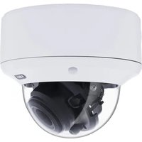
4.2. Description HDCC32512, HDCC35512
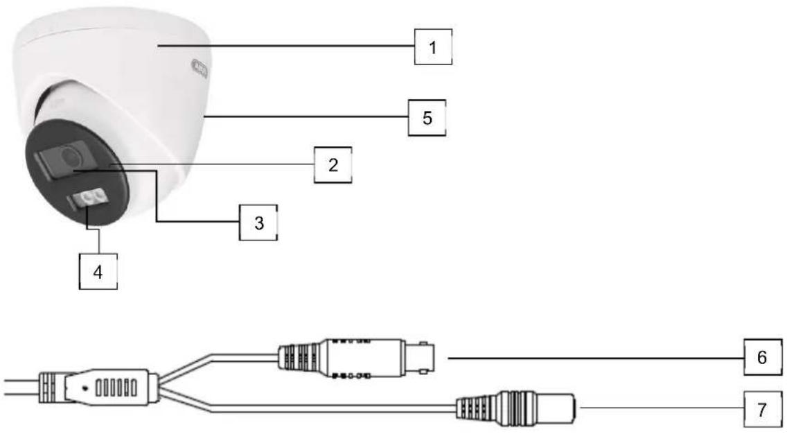
text_image
1 5 2 3 4 6 7| 1 | Camera housing with ball head |
| 2 | Microphone |
| 3 | Objective |
| 4 | IR LEDs / white light LED |
| 5 | Speaker (HDCC52512 only, on the back of the camera) |
| 6 | Video output (BNC, imprint "TVI") |
| 7 | Voltage connection (5.5x2.1mm, hollow plug) |
5. Assembly / Installation
5.1. Mounting the camera

ATTENTION!
The camera must be disconnected from the mains voltage during installation.
Use dowels and screws suitable for the surface to fix the camera. Drill appropriately sized holes for the wall plugs used. An opening is provided on the base plate of the camera mount for lateral cable routing.
HDCC32512, HDCC35512 HDCC52512, HDCC55512
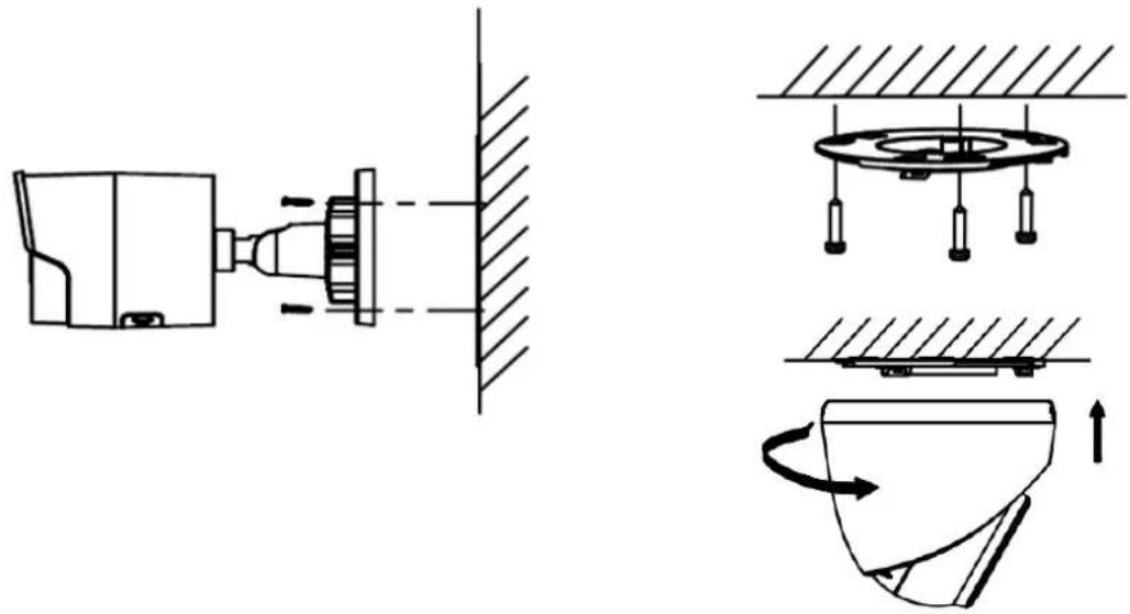
natural_image
Technical line drawing showing mechanical assembly and rotation of a component (no text or symbols)5.2. Alignment of the camera
| Carefully loosen the union nut (#1). Then align the camera as required.#2: Panning 360°#3: Tilt 90°#4: Rotation 360° | The camera is panned by turning the camera cap. The camera (ball) head is used to tilt and rotate the camera.#1: Panning 360°#2: Tilt 75°#3: Rotation 360° |
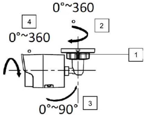  | 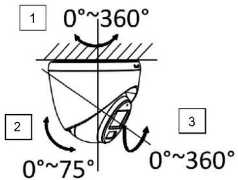  |

The effective IR / white light range depends on the location. Light-absorbing surfaces or no light-reflecting objects in the field of vision reduce the IR / white light range or cause the video image to be too dark. Furthermore, reflective objects in the direct vicinity of the camera (gutter, wall) can result in disturbing reflections of the IR / white light in the image.
5.3. Power supply
| ATTENTION!Before starting the installation, make sure that the supply voltage and the rated voltage of the camera match. | ||
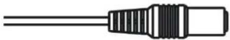 | 12 VDC, barrel connector, 5.5x2.1mm | |
The cameras require a 12 VDC power supply. The polarity of the DC voltage supply must be observed!
5.4. Attaching the video cable
To transmit the HD-TVI video signal from the camera to a recorder, an RG59 coaxial cable with a BNC plug (male, male) must be connected to the connection labeled "TVI". The cable length to the next device must not exceed 200 meters for 2 megapixels or 150 meters for 5 megapixels.

To ensure optimum transmission quality of the HD-TVI signal, it is necessary that the cable is not kinked, crushed or laid at too small a radius (min. bending radius 6 cm). If the cable is damaged or has become porous due to the ageing process, this can also affect the signal or image quality (e.g. shadows around edges, loss of signal).
6. On-screen menu
6.1. Opening the on-screen menu (OSD)
The on-screen display (OSD) of this camera can only be opened via the ABUS Analog HD Recorder (TVVR33*** or HDCC900**). Please refer to the operating instructions for the ABUS recorder.
6.2. Description of the on-screen menu (OSD)
Press the OSD menu control button to open the OSD on-screen menu (local interface (HDMI) of the recorder / camera / PTZ menu / menu) ("Shutter+" for Enter). Detailed settings can be made via this on-screen menu.
MAIN MENU

text_image
MAIN MENU VIDEO FORMAT <2M25> EXPOSURE ↓ LIGHT SETTINGS ↓ VIDEO SETTINGS ↓ AUDIO SETTINGS ↓ ALARM SETTINGS ↓ FACTORY DEFAULT ↓ EXIT ↓ SAVE&EXIT ↓Video format
| Function Description | |
| Video format Setting for the video resolution | |
| Options:3K20: 5 Megapixel @ 20 fps (TVCC55512 only)4M25: 4 Megapixel @ 25 fps (TVCC55512 only)4M30: 4 Megapixel @ 30 fps (TVCC55512 only)2M25: 2 Megapixel @ 25 fps2M30: 2 Megapixel @ 30 fps | |
Exposure
General exposure settings are set in this menu item, e.g. whether the camera should process high contrasts or whether the camera requires special settings for night vision.
| Function | Description | |
| Exposure mode | Global: | General automatic exposure setting without WDR function |
| BLC: | Automatic exposure setting with back light compensation. The BLC function improves the image display with medium image contrasts. | |
| HLC: | High Light Compensation (spot light suppression) | |
| WDR: | Automatic exposure setting with digital WDR function (Wide Dynamic Range). The WDR function | |
| is used to improve the display of high image contrasts.HLS: High Light Suppression: If the brightness in the video image exceeds a certain threshold value at various points, these areas or pixels are displayed in black. | ||
| AGC Automatic gain control. | The higher the setting, the brighter the video image appears in low lighting conditions, but the higher the image noise.Low: LowMedium: MediumHigh: High | |
| Anti-banding Function for sup | pressing horizontal banding in the video image (also "anti-flicker")OFF: Function deactivatedLevel 1-5: Level selection for more or less suppression of streaking | |
| Back Back to the previous menu pa | ge | |
| Exit | Exiting the menu | |
| Save&Exit | Saving and exiting the menu | |
LIGHT SETTINGS
The mode for day/night switching (or Gecko/IR switching) is set in this menu item.
| Function Description | |
| SMART Event-controlled switching from IR (night) mode to gecko/white light mode. An event can be motion detection, intrusion detection or tripwire detection with person/vehicle detection.An ABUS HDCC90003, HDCC90013 or HDCC90023 video recorder is required for this function. These recorders have the corresponding event detectors with person/vehicle detection. The recorder controls the switchover.IR Light: On: IR LEDs active in night modeOff: IR LEDs deactivated in night modeSmart IR: Function to reduce the over-illumination of IRlight with close objectsOn: Function activeOff: Function deactivatedD->N Threshold (1-9): Switching threshold from day to night modeN->D Threshold (1-9): Switchover threshold from night to day modeBack: Back to the previous menu page | |
| IR Automatic activation/deactivation of day or night mode. The picture brightness controls the switchover depending on the light intensity.IR Light: On: IR LEDs active in night modeOff: IR LEDs deactivated in night modeSmart IR: Function to reduce the over-illumination of IRlight with close objectsOn: Function activeOff: Function deactivatedD->N Threshold (1-9): Switching threshold from day to night mode | |
| N->D Threshold (1-9): Switchover threshold from night to day modeBack: Back to the previous menu page | |
| WHITE LIGHT The camera remains permanently in color or gecko mode. | White Light: Auto: Automatic activation of the white lightLEDs in the darkOFF: Deactivation of the white light LEDs. To obtain an acceptable video image, there must be some residual light in the scene (e.g. street lamp or front door lamp)Threshold: Threshold value, but at which brightness levelthe white light is switched on.Level: Brightness level of the white light LEDs |
Video settings
General image settings such as contrast or mirroring of the video image are made in this menu item.
| Function Description | |
| Image Mode Two different basic camera settings can be set here. | |
| STD: Standard settingHIGH-SAT: Setting for a more intense color pictureHIGHLIGHT: Contrast-altered image with smoothing effect | |
| White Balance Auto: Automatic white balance | |
| Manual: Manual white balanceR Gain: Gain factor for the red component in the imageB Gain: Gain factor for the blue component in the imageBack: Back to the previous menu pageExit: Exit the menuSave&Exit: Saving and exiting the menu | |
| Brightness | (1~9): Setting for the picture brightness |
| Contrast | (1~9): Setting for the image contrast |
| Sharpness | (1~9): This function can be used to electronically change the perception of image sharpness. |
| Saturation | (1~9): Saturation of the video image |
| (3D)DNR | (1~9): Setting for the noise reduction function. The higher the set value, the more noise is removed from the video image by the software. |
| Back | Back to the previous menu page |
| Exit | Exiting the menu |
| Save&Exit | Saving and exiting the menu |
Audio Settings
| Function Description | |
| Audio Deactivation or activation of the built-in microphone. An ABUS HDCC90003, HDCC90013 or HDCC90023 video recorder is required for this function.OFF: Deactivation of the microphoneON: Activation of the microphoneNote: Observe country-specific regulations for the use of the audio function. | |
| MIC | |
| MIC Volume 1-9. Volume setting for the built-in microphone | |
| NOISE REDUCTION Activation (ON) of the noise reduction function. | |
| SPEAKER | The built-in microphone and speaker offer the possibility of 2-way audio communication via the ABUS Link Sation app and an ABUS Analog HD DVR to the camera (only available with HDCC32512 & HDCC52512). The connection between app and recorder can be made via the Link Station Cloud (via "QR code") or via IP integration.Activation (ON) of the internal loudspeaker is possible. An ABUS HDCC90003, HDCC90013 or HDCC90023 video recorder is required for this function. |
| SPEAKER VOLUME Only for HDCC32512 & HDCC525121-9. Volume setting for the built-in speaker | |
| Back Back to the previous menu page | |
| Exit | Exiting the menu |
| Save&Exit | Saving and exiting the menu |
Alarm Settings
With the alarm function, it is possible to generate a red and blue flashing light and/or an acoustic message on the camera. The event linking takes place in an ABUS Analog HD DVR. An ABUS HDCC90003, HDCC90013 or HDCC90023 video recorder is required for this function.
| Function Description | |
| ALARM SOURCE The variant of the acoustic output can be set here: Siren, Attention, Warning, Welcome, Danger | |
| ALARM TIMES Settin | g the repetition of the alarm output (1-5 times) |
| ALARM VOLUME | Volume setting for the audible alarm output in 3 levels (LOW/MEDIUM/HIGH) |
| Back Back to the previous menu page | |
| Exit | Exiting the menu |
| Save&Exit | Saving and exiting the menu |
Factory Default (Reset)
| Function Description | |
| Factory Default Resetting all | camera settings in the main menu to factory settings |
| Confirm Confirm processCancel Cancel process |
Exit
| Function Description | |
| Back Exit the menu without saving | |
Save&Exit
| Function Description | |
| Save&Exit Saving all settings | and exiting the OSD menu |
7. Maintenance and cleaning
7.1. Maintenance
Regularly check the technical safety of the product, e.g. damage to the housing.
If it can be assumed that safe operation is no longer possible, the product must be taken out of service and secured against unintentional operation.
It can be assumed that safe operation is no longer possible if
- the device shows visible damage,
• the device no longer works
Please note:
The product is maintenance-free for you. There are no components inside the product for you to check or maintain, never open it.
7.2. Cleaning
Clean the product with a clean, dry cloth. For heavier soiling, the cloth can be lightly moistened with lukewarm water.

Make sure that no liquids get into the appliance.
Do not use chemical cleaners, as this could damage the surface of the housing and the screen (discoloration).
8. Waste disposal
Attention: EU Directive 2002/96/EC regulates the proper return, treatment and recycling of used electronic equipment. This symbol means that, in the interests of environmental protection, the appliance must be disposed of at the end of its service life in accordance with the applicable legal regulations and separately from household or commercial waste. The old appliance can be disposed of at official collection points in your country. Follow the local regulations when disposing of the materials. For more details on take-back (also for non-EU countries), please contact your local administration. Separate collection and recycling conserves natural resources and ensures that all regulations for the protection of health and the environment are observed when recycling the product.
HDCC32512 / HDCC52512
HDCC52512 / HDCC55512
natural_image
Exterior view of a white and black Access Security Camera (ABSS) device with a digital display on the right (no text or symbols visible)
natural_image
Close-up of a white surveillance camera with a black circular lens and control panel (no visible text or symbols)Mode d'emploi
Version 09/2025 (V1.1)
CE
text_image
FRONT Drill Temperature Φ1 A Φ2 Φ3 Hode A: for cables routed through the ceiling. Screw hole 1: for mounting domeGabarit de perçage
natural_image
Technical line drawing showing mechanical assembly and component alignment (no text or symbols)natural_image
Exterior view of a white and black Access Security Camera (ABSS) device with a digital display on the right (no text or symbols visible)
natural_image
Close-up of a white surveillance camera with a black circular lens and display screen (no visible text or symbols)text_image
FRONT Drill Temperature Φ1 A Φ2 Φ3 Hode A: for cables routed through the ceiling. Screw hole 1: for mounting domeBoorsjabloon
natural_image
Technical line drawing showing mechanical assembly and component alignment (no text or symbols)natural_image
Exterior view of a white and black Access Security Camera (ABSS) device with a digital display on the right (no text or symbols visible)
natural_image
Close-up of a white surveillance camera with a black circular lens and display screen (no visible text or symbols)text_image
FRONT Drill Temperature Φ1 A Φ2 Φ3 Hode A: for cables routed through the ceiling. Screw hole 1: for mounting domeBoreskabelon
natural_image
Technical line drawing showing mechanical assembly and component alignment (no text or symbols)natural_image
Exterior view of a white and black ARB security camera (no visible text or symbols)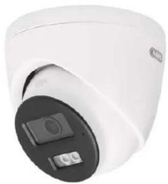
natural_image
Close-up of a white cylindrical security camera with a black circular dial and control buttons (no visible text or symbols)text_image
FRONT Drill Temperature 10° Φ1 A Hode A: for cables routed through the ceiling. Bumper hold 1: for mounting dome Φ3Modello di foratura