Smart Pro 11 - Water pump Steinbach - Free user manual and instructions
Find the device manual for free Smart Pro 11 Steinbach in PDF.

| Brand | Steinbach |
| Model | Smart Pro 11 |
| Product type | Inverter filter pump |
| Power supply | 220-240 V / 50 Hz |
| Maximum power | 1100 W |
| Maximum flow rate | 27,000 l/h |
| Maximum head height | 14.5 m |
| Recommended pool volume | Up to 81,000 l |
| Water temperature | 10 °C to 35 °C |
| Hose connection | D 50 mm adhesive connector |
| Protection rating | IPX5 |
| Protection class | I |
| Insulation class | F |
| Operating principle | Self-priming |
| Technology | Inverter (variable speed) |
| Integrated timer | Yes, up to 4 programs |
| Pre-filter | Yes, removable |
| Display functions | Time, speed, power, mode, timer |
| Cleaning | Clean pre-filter and body with a damp cloth |
| Winterizing | Drain completely, store frost-free (≥ +5 °C) |
| Safety | Protected by 30 mA RCD, do not use during thunderstorms |
| Delivery contents | Pump, 2 D50 adhesive connectors, 2 O-rings, 2 union nuts, manual |
Frequently Asked Questions - Smart Pro 11 Steinbach
User questions about Smart Pro 11 Steinbach
0 question about this device. Answer the ones you know or ask your own.
Ask a new question about this device
Download the instructions for your Water pump in PDF format for free! Find your manual Smart Pro 11 - Steinbach and take your electronic device back in hand. On this page are published all the documents necessary for the use of your device. Smart Pro 11 by Steinbach.
USER MANUAL Smart Pro 11 Steinbach
natural_image
3D rendering of a gray industrial pump or motor component with no visible text or symbolsÜbersicht
Steinbach
041300Y/041301Y_V25070 dede041301Y_V2507
Steinbach
B

natural_image
Simple line drawing of a cylindrical tank connected to a water pump and a small container (no text or symbols)Steinbach
041300Y/041301Y_V25070 enen041301Y_V2507
Steinbach
B
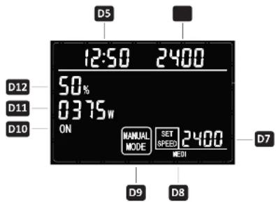
Display in manual mode
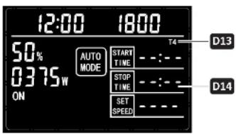
Display in automatic mode
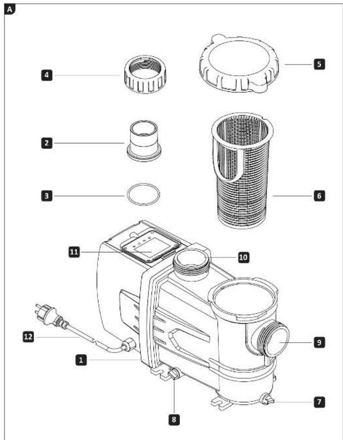
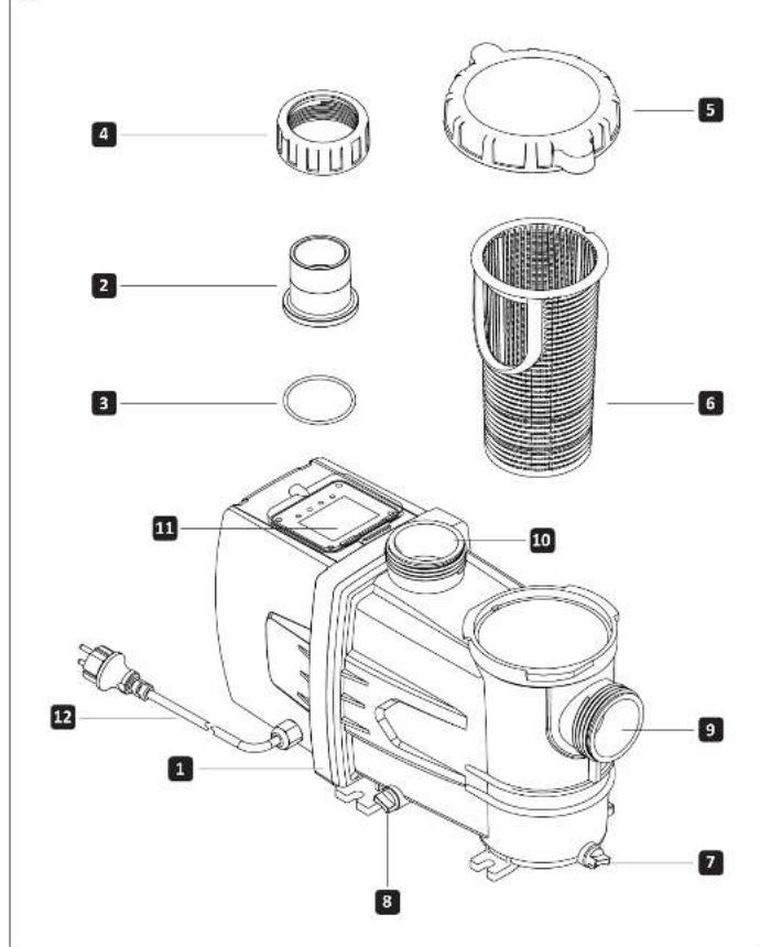
Scope of delivery
1 Inverter filter pump
2 Adhesive connection D 50 (2x)
3 O-ring (2x)
4 Cap nut (2x)
Device parts
5 Pre-filter cover incl. O-ring (pre-assembled if necessary)
6 Prefilter
7+8 Drain screw
9 Pump/suction line
10 Pump/pressure line
11 Display
12 Power cord
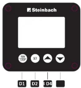
(B) Display: Operating and display elements
D1 Button RUN/STOP
D2 Button SET
D3 Button Control/navigation UP
D4 Button Control/navigation DOWN
DS Display Time
D6 Display Actual speed (1/min)
D7 Display Setpoint speed (1/min)
D8 Display Preset speed (Low, Medium, High, Full)
D9 Display Operating mode (manual/automatic)
D10 Display Operating status
D11 Display Current power consumption of the pump
D12 Display Current power consumption compared to full load
D13 Display Timer (T1, T2, T3, T4)
D14 Display Timer times (start time / end time / speed (1/min))
Steinbach
041300Y/041301Y_V25070 enen041301Y_V2507
Steinbach
Table of contents
Overview....17
Scope of delivery....19
General information 21
Read and keep the operating instructions....21
Explanation of symbols....21
Safety....22
General safety instructions....22
Preparation 24
Choosing a location....24
Description....24
Description of the filter pump 24
Setting the time....24
How the timer works 25
Programming and activating the timer....25
Deactivating the timer 25
Filter time 26
Initial operation 26
Preparing the pump 26
Connecting the pipes 26
Vent the pump 27
Operation....27
Pump operation 27
Cleaning 28
Cleaning the pump 28
Testing 28
Storage....28
Winter storage 28
Troubleshooting 29
Technical data....30
Declaration of conformity....30
Disposal 30
Disposing of the packaging 30
Disposing of the old device....30
General
Read and keep the operating instructions
These operating instructions are for the Steinbach Smart Pro 7.5 and 11 inverter filter pumps, hereinafter referred to as the "device" or "pump."
Read the operating instructions carefully, especially the safety instructions, before using the device. Failure to follow these operating instructions may result in serious injury or damage to the device. Keep the operating instructions for future reference. If you pass the device on to third parties, be sure to include these operating instructions.
Intended use
This device is designed exclusively for pumping pool water up to a maximum temperature of 35^ C. The device pumps the pool water from the pool to the filter system.
It is intended for private use only and is not suitable for commercial use. Only use the device as described in this operating manual. Any other use is considered improper and may result in property damage or even personal injury. The device is not frost-proof. The device is not a children's toy.
The manufacturer or dealer accepts no liability for damage resulting from improper or incorrect use. Only use the device when it is properly connected.
Explanation of symbols
The following symbols are used in this operating manual, on the device, or on the packaging.

Here you will find useful additional information.

Make sure you fill with water before operating the pump for the first time.

Never use sharp knives or other pointed objects to open the packaging. You could damage the contents.
Safety
The following signal words are used in this operating manual.
WARNING!
This signal symbol/word indicates a hazard with a medium degree of risk which, if not avoided, could result in death or serious injury.
ATTENTION!
This signal symbol/word indicates a hazard with a low degree of risk which, if not avoided, could result in minor or moderate injury.
NOTE!
This signal word warns of possible damage to property.
General safety instructions
WARNING!
Risk of electric shock!
Faulty electrical installation or excessive mains voltage can result in electric shock.
» Only connect the mains cable if the mains voltage of the socket corresponds to the information on the type plate.
» Only connect the mains cable to an easily accessible socket so that you can quickly disconnect the mains cable from the mains in the event of a fault.
» Only operate the device from a socket with a protective earth connection that is fused with a maximum of 16A.
» The device must be supplied via a residual current device (RCD) with a rated residual current of no more than 30 mA.
» Do not operate the device if it shows visible damage or if the power cord or power plug is defective.
» Do not open the device; leave repairs to qualified personnel. Please contact the service address on the back of the instructions. Liability and warranty claims are excluded for repairs carried out independently, improper connection, or incorrect operation.
»Never touch the power cord with wet hands.
» Never pull the power cord out of the socket by the cord; always grasp the power plug. »Never use the power cord as a carrying handle.
» Keep the device and the power cord away from open flames and hot surfaces. » Do not place any objects on the power cord.
»Do not bury the power cord.
» Lay the power cord so that it does not become a trip hazard. »Do not kink the power cord or lay it over sharp edges.
» If necessary, use only extension cords that are suitable for outdoor use. Using an extension cord suitable for outdoor use reduces the risk of electric shock.
» Do not use the device during a thunderstorm. Switch it off and disconnect the power cord from the power outlet. » Always switch off the device and disconnect it from the power supply when you are not using it, cleaning it, or if a malfunction occurs.
» Only parts that correspond to the original device data may be used for repairs. This device contains electrical and mechanical parts that are essential for protection against sources of danger.
» Only use replacement parts and accessories supplied or recommended by the manufacturer. The use of third-party parts will immediately void all warranty claims.
Safety instructions for persons
WARNING!
Dangers for children and persons with reduced physical, sensory, or mental capabilities (e.g., partially disabled persons, elderly persons with limited physical and mental capabilities) or lack of experience and knowledge
(e.g., older children).
Improper use of the device can result in serious injury or damage to the device.
» Only allow others to use the device after they have read and understood the instructions or have been instructed on the proper use and associated hazards.
» Never leave persons with reduced physical, sensory, or mental capabilities (e.g., children or intoxicated persons) or lack of experience and knowledge (e.g., children) unattended near the device.
» Never allow children or persons with reduced physical, sensory, or mental capabilities or lack of experience and knowledge to use the device.
»Do not allow children to perform cleaning or user maintenance.
»Children must not play with the device or the connection cable.
WARNING!
Risk of injury due to lack of qualification!
Lack of experience or skill in handling the necessary tools and lack of knowledge of regional or normative regulations for the required manual work can result in serious injury or damage to property.
» For all work whose risks you cannot assess based on sufficient personal experience, consult a qualified specialist.
» Do not operate the device in an impaired state (e.g., under the influence of drugs, alcohol, or medication).
NOTE!
Improper handling of the device may result in damage to the device.
» Select a location for the device that is protected from the weather.
» Ensure adequate air circulation to prevent the motor from overheating.
»Do not allow the device to run dry (without water).
»Never place the device or parts of it in the pool.
Unpack and check the contents of the delivery
WARNING!
Risk of suffocation from packaging material!
Getting your head caught in packaging film or swallowing other packaging material can lead to death by suffocation. Children and mentally impaired persons who are unable to assess the risks due to a lack of knowledge and experience are particularly at risk.
» Ensure that children and mentally impaired persons do not play with the packaging material.
Steinbach
041300Y/041301Y_V25070 enen041301Y_V2507
Steinbach
Preparation
Choosing a location
The pump is well protected against the ingress of water and foreign objects. However, a location that is protected from severe weather conditions will further reduce contamination and wear.
The following requirements must be met or taken into account:
» Position of the pump between the suction connection and the inlet nozzle and at a sufficient distance from the pool wall so that the pump cannot be used as a means of access »Position of the pump below the water level »Maximum distance of three meters from the pool »Stable, solid, and level base, e.g., washed concrete slab
The device is equipped with frequency converters that can generate high-frequency leakage currents due to the nature of the system. To ensure proper functioning and interference suppression, a correctly connected, standard-compliant protective earth conductor (PE) must be installed in the building's electrical system and the power supply cable must be as short as possible.
Description
Description of the filter pump
natural_image
Simple line drawing of a cylindrical tank connected to a piping system with a valve (no text or symbols)The filter pump transports the pool water from the pool to the filter system. An integrated pre-filter retains larger dirt particles and thus protects the pump from damage. Thanks to inverter technology, the speed can be individually adjusted, allowing the flow rate to be optimally matched to requirements. At reduced speeds, energy consumption is significantly reduced, enabling efficient and resource-saving operation.
Setting the time
- Press and hold the RUN/STOP D1 and SET D2 buttons simultaneously for approx. 3 seconds. The hour display on the Time D5 display flashes. The hour display can be set.
- Press the Control/Navigation UP D3 or Control/Navigation DOWN D4 buttons repeatedly to set the hours. Press the SET D2 button to confirm the entry. The minute display on the Time D5 display flashes. The minutes can be set.
- Press the Control/Navigation UP D3 or Control/Navigation DOWN D4 buttons repeatedly to set the minutes of the time. Press the SET D2 button to confirm the entry. The clock is now set.
24 26
The clock continues to run for several days even without a power supply.
How the timer works
The integrated timer can be used to automatically start and stop the pump for the selected time. Up to 4 timers can be programmed. Each timer has 3 parameters: start time, end time, and target speed (1/min). The timers are shown on the display as "T1," "T2," "T3," and "T4." When programming the time and speed parameters for the first time, programming starts automatically with the first time and speed segment, "T1." When programming a timer, all parameters (start time, end time, and target speed (1/min)) are displayed. The parameter currently being programmed flashes.
The times and speeds remain stored for several days even without power supply.
Programming and activating timers
The switch-on and switch-off times of each timer must be different and the timers must not overlap. If the timer times overlap, the current entry cannot be saved.
Press the SET D2 button to start programming your timer ("T1"). Use the Control/Navigation UP D3 or Control/Navigation DOWN D4 buttons to program the start time, end time, and desired speed (1/min). The parameter to be set flashes.
Once you have set the times or speeds as desired, press SET D2 to save them. Once you have programmed the first timer, press the SET D2 button for 3 seconds to save the timer and exit.
Press the Control/Navigation DOWN D4 button to move to the second timer ("T2"). Repeat the above procedure to program another timer. It is not necessary to program all four timers. After 8 seconds without input, the settings are automatically saved and the timer menu is exited. To return to this timer, first press the Control/Navigation DOWN D4 button and then the SET D2 button until you reach the desired timer. Continue with the above programming steps. The timer is now set and activated.
If you have made a mistake when programming a timer, you can go back by pressing the SET D2 button once. Then switch to the time or speed setting you want to change by pressing the SET button D2 until that setting flashes. Use the Control/Navigation UP button D3 or Control/Navigation DOWN button D4 to change the setting.
Deactivating the timer
There are two ways to deactivate the desired timer: 1. To delete the current settings for the timer, set the hour in the start time to "23" and press the Control/Navigation UP D3 button once; all settings under this timer will be deleted. 2. Set the hour in the start time to "00" and press the Control/Navigation DOWN button D4 once to delete all settings in this timer. The timer is now deactivated.
Steinbach
041300Y/041301Y_V25070 enen041301Y_V2507
Steinbach
Filter time
The water in the pool should be circulated at least twice within 24 hours. If the pool is used more intensively, it should be circulated 3 to 5 times per day.
Initial operation
WARNING!
Danger to life due to operation of the water treatment system during bathing!
Hair or clothing can be sucked into the suction opening of the pool and, in extreme cases, trap people underwater and prevent them from surfacing.
» Never operate water treatment system equipment while people are in the pool.
» Prevent access to the pool while water treatment system equipment is in operation.
Check before starting up
The device is outside the pool and the power cord is disconnected from the mains.
Prepare the pump
The pump is only partially pre-assembled when delivered.

Tighten all screw connections by hand only. Excessive tightening of the screw connections will damage the seals and plastic parts. Do not use tools. Slightly leaking screw connections can be sealed with Teflon tape.
- Unscrew the prefilter cover including O-ring 5 counterclockwise.
- Lift the prefilter cover including O-ring 5 off the pump housing.
- Insert the prefilter 6 into the pump. The prefilter is already inserted in the pump when delivered.
- Place the prefilter cover including O-ring 5 on the pump housing and turn it clockwise until it is tight.
- Insert one O-ring seal 3 into the recess of the suction line 9 and pressure line 10 of the pump.
- Place one adapter 2 on the suction line 9 and one on the pressure line 10 of the pump.
- Place the corresponding union nut 4 over the adapters 2 and tighten them clockwise by hand.
The pump is now ready for operation and can be connected to the lines.
Connecting pipes
Use suitable D50 piping material for the connections described. When using ∅ 32/38 mm swimming pool hoses (e.g. INTEX with threaded connection), additional adapters are required, which are not included in the scope of delivery. Suitable adapters can be found in our webshop at: www.steinbach-group.com
Prepare the following materials (not included in the scope of delivery):
- Pressure pipe
- Suction pipe
- Mounting material for the pipes
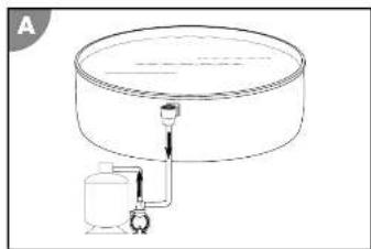
Proceed as follows to connect the pipes to the pump and filter tank as shown in Figure A at the beginning of these instructions:
- Lay the suction pipe 9 from the pool to the pump. Keep the suction pipe 9 as short as possible, as the pump performance will decrease with increasing length.
- Lay the pressure pipe 10 from the pump to the filter tank.
The pipes are now connected.
Vent the pump
The pump is below the water level
- Open the water supply to the pump.
- Open the prefilter cover including the O-ring 5. The prefilter fills with water.
- Allow the prefilter to fill completely with water
- Close the prefilter cover including the O-ring 5
The pump below the water level is vented.
Pump is above the water level
- Open the prefilter cover including the O-ring 5
-
Fill the prefilter with water (e.g., garden hose) until it is approx. 2-4 cm below the upper edge.
-
Close the prefilter cover including the O-ring 5.
The pump above the water level is now vented.
Operation
WARNING!
Danger to life due to operation of the water treatment system during bathing!
Hair or clothing can be sucked into the suction opening of the pool and, in extreme cases, trap people underwater and prevent them from surfacing.
» Never operate water treatment system equipment while people are in the pool.
» Prevent access to the pool while water treatment system equipment is in operation.
ATTENTION!
A damaged device or damaged accessories can cause injury.
»Check the device and accessories (see chapter Inspection).
Pump operation
- Ensure that all hoses and pipes are connected correctly and that the water level in the tank is at least 2.5 to 5 cm above the opening of the suction line.
- Check the valve position of your filter system before activating the pump.
- Connect the pump's power plug 12 to the power supply.
- Switch on the pump by pressing the RUN/STOP D1 button.
The pump is now active. If you have previously set the timer and performance settings, the pump will
operate automatically according to your specifications.
The pump is running. - Check the pump for unusual noises.
- If there is air in the system, vent the system again.
- Press the RUN/STOP button D1 on the display to stop the pump manually.
Manual shutdown deactivates the timer.
The pump is switched off.
Steinbach
041300Y:041301Y_V25070 enen 041301Y_V2507
Steinbach
Cleaning
Clean the device exclusively with standard bathroom cleaner, clear tap water, and a lint-free cloth. Aggressive cleaning agents can damage the device. Dry the device with a lint-free cloth.
Cleaning the pump
-
Close the shut-off valves or block the water flow to the pool connection pipes.
-
Unscrew the pre-filter cover including the O-ring 5.
-
Remove and empty the pre-filter 6
-
Clean the pump and the parts included in the scope of delivery with a slightly damp cloth.
-
Dry the pump and the parts included in the scope of delivery with a dry cloth.
-
Insert the prefilter 6 and fit the prefilter cover including the O-ring 5.
-
Open the shut-off valves or restore the water flow to the pool connection pipes.
The pump is now clean.
Testing
Check the following before each use:
»Is there any visible damage to the device?
»Is there any visible damage to the controls?
»Are the accessories in perfect condition?
»Are all cables in perfect condition?
"Is the inlet unblocked?"
"Are the ventilation slots free and clean?"
Do not operate a damaged device or accessory. Have it checked and repaired by the manufacturer or its customer service department or a qualified specialist.
Storage
As soon as the outside temperature falls below +5°C for a prolonged period, the pump should be winterized to prevent damage from ice formation (frost burst).

Fixed water pipes do not necessarily have to be uninstalled. Provided that the pump location is protected from coarse contamination and severe weather conditions, it is sufficient to drain the water from the pump and the water pipes. Frost damage is expressly excluded from the warranty.
Winter storage
- Disconnect the pump from the power supply 12
- Disconnect the connecting pipes to the pool and drain the pipes.
- Remove the drain screws 7 and 8 on the pump housing and drain the pump completely.
- Clean the device thoroughly (see chapter "Cleaning").
- Allow the device to dry completely after cleaning.
- Screw the drain screws 7 and 8 into the pump housing.
- Store the device in a dry and frost-free place (>= +5 °C) without direct sunlight.
The device is now stored.
Troubleshooting
| Problem: | Cause: | Solution: |
| Air bubbles are coming out of the inlet nozzle or the pump is making unusual noises. | The pump sucks air. | Check all lines and seals for leaks. |
| Check the water level in the pool and top up with water if necessary until the water surface is 2.5–5 cm above the suction pipe connection. | ||
| The water level in the pool is too low. | Raise the water level of the pool. | |
| The prefilter basket is misplaced/clogged. | Empty the prefilter basket. | |
| The suction line is misplaced/blocked. | Clean the suction line. | |
| The pump is not working. | The timer is set. | Check the timer settings. Switch on the pump. |
| The external timer is set. | Check the running times of the external timer. | |
| During operation, the WLAN signal or radio reception is disrupted. | The device is equipped with frequency converters that can generate high-frequency leakage currents due to the nature of the system. | If you notice any faults despite a short power cord, stop using the affected device and have the power supply (e.g., power outlet, extension cord) checked by a qualified electrician immediately. |

If the fault cannot be rectified, please contact an authorized technician or the Steinbach support team.
Steinbach
041300Y:041301Y_V2507

Technical specifications
| SMART PRO 7,5 SMART PRO 11 | ||
| Item number: 041300Y 041300Y | ||
| Functional principle: well printing well printing | ||
| Prolifer: available available | ||
| Timers: yes yes | ||
| Power supply: 220.240 VV, 50 Hz 220.240 VV, 50 Hz | ||
| Power: max. 750 W max. 1,100 W | ||
| Pump capacity: max. 21,000 l/h max. 27,000 l/h | ||
| Delivery head: | max. 13,0 m | max. 14,5 m |
| Pool size (water capacity): | up to 63,000 l | up to 81,000 l |
| Water temperature: | 10 °C - 35 °C | 10 °C - 35 °C |
| Connection size: | Adhesive connection D50 | Adhesive connection D50 |
| Protection type: | IPX5 | IPX5 |
| Protection class: | I | I |
| Insulation class: | F | F |
Declaration of conformity


With the CE mark, the manufacturer confirms that the product complies with the applicable directives. The full text of the EU declaration of conformity can be requested from the address listed at the end of this manual.
Disposal
Dispose of packaging

Dispose of the packaging separately. Put cardboard and paperboard in the waste paper bin and plastic film in the recycling bin.
Dispose of old devices

Old devices must not be disposed of with household waste! If the device can no longer be used, every consumer is legally obliged to dispose of old devices separately from household waste, e.g. at a collection point in their municipality/district. This ensures that old devices are recycled properly and that negative effects on the environment are avoided. For this reason, electrical devices are marked with the above symbol.
Steinbach
041300Y/041301Y_V2507

Aperçu
A
Steinbach
041300Y/041301Y_V25070 frfr 041301Y_V2507
Steinbach
B

natural_image
Simple line drawing of a cylindrical tank connected to a water pump (no text or symbols)Steinbach
041300Y/041301Y_V25070 Ilt 041301Y_V2507
Steinbach
B