
90-095 - Heating NEO tools - Free user manual and instructions
Find the device manual for free 90-095 NEO tools in PDF.

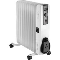
| Product type | Infrared heating panel |
| Brand | NEO tools |
| Model | 90-095 |
| Nominal power | 2000 W (max) / 1000 W (min) |
| Supply voltage | 220-240 V ~ 50 Hz |
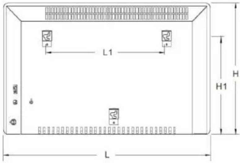
| Dimensions (L x H x D) | 835 x 450 x 538 mm (with brackets) |
| Approximate weight | 5 kg |
| Material | Metal and plastic |
| Mounting type | Wall-mounted (supplied with brackets and screws) |
| Heat levels | 2 (low / high) |
| Control | Touch panel + remote control + TuyaSmart app (Wi-Fi 2.4 GHz) |
| Main features | Adjustable thermostat, timer (0-24 h), ECO mode, open window detection, child lock, °C/°F display |
| Safety | Overheat protection (automatic shutoff), hot surface (burns), safety distance 0.9 m |
| Maintenance and cleaning | Wipe with a soft damp cloth after cooling; do not use abrasive products |
| Spare parts and repairability | Parts available from the manufacturer; do not repair yourself (warranty void) |
| General information | Indoor use only, do not cover, compatible with Wi-Fi 2.4 GHz |
Frequently Asked Questions - 90-095 NEO tools
User questions about 90-095 NEO tools
0 question about this device. Answer the ones you know or ask your own.
Ask a new question about this device
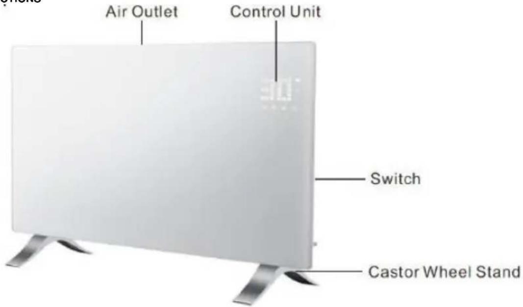
Download the instructions for your Heating in PDF format for free! Find your manual 90-095 - NEO tools and take your electronic device back in hand. On this page are published all the documents necessary for the use of your device. 90-095 by NEO tools.
USER MANUAL 90-095 NEO tools
natural_image
White rectangular electronic device with metallic legs and a digital display on top (no visible text or symbols)PL PANEL GRZEWCZY
EN PANEL HEATER
DE PANELHEIZUNG
HU PANEL FÜTÖ
RO ÎNCĂLZITOR PANEL
CS OHŘEV PANELU
SK OHRIEVAČE PANELU
SL PLOČNI GRELEC
LT PANELÈS ŠILDYTUVAS
LV Paneļa sildītājs
IT RISCALDATORE A PANNELLO
NL PANEELVERWARMING
FR PANNEAU CHAUFFANT
PL
This product is only suitable for occasional use or for use in well-insulated areas
DE
| Model | L mm | H mm | L1 mm | H1 mm |
| 90-093 | 515 | 450 | 218 | 344 |
| 90-094 | 675 | 450 | 378 | 344 |
| 90-095 | 835 | 450 | 538 | 344 |
Montaż podstawek
natural_image
Technical line drawing of a mechanical assembly with a pipette and bolts (no text or symbols)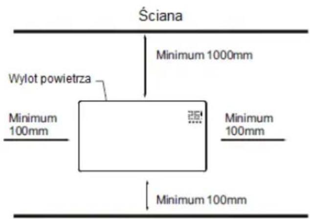

/This declaration of conformity is issued under the sole responsibility of the manufacturer/
IEC 62321-6:2015; IEC 62321-7-1:2015; IEC 62321-7-2:2017; IEC 62321-8:2017
/Signed for and on behalf of:/
/GRUPA TOPEX Quality Agent/
/This declaration of conformity is issued under the sole responsibility of the manufacturer/
IEC 62321-6:2015; IEC 62321-7-1:2015; IEC 62321-7-2:2017; IEC 62321-8:2017
/Signed for and on behalf of:/
/GRUPA TOPEX Quality Agent/
/This declaration of conformity is issued under the sole responsibility of the manufacturer/
IEC 62321-6:2015; IEC 62321-7-1:2015; IEC 62321-7-2:2017; IEC 62321-8:2017
/Signed for and on behalf of:/
/GRUPA TOPEX Quality Agent/
NOTE: BEFORE THE EQUIPMENT IS USED FOR THE FIRST TIME, READ THIS INSTRUCTION MANUAL AND KEEP IT FOR FUTURE REFERENCE. PEOPLE WHO HAVE NOT READ THIS INSTRUCTION SHOULD NOT ASSEMBLE, LIGHT, ADJUST OR OPERATE THE UNIT
This product is only suitable for well insulated spaces or occasional use.
DETAILED SAFETY REGULATIONS

ATTENTION!
Read carefully-The infrared heater is designed for safe operation. Nevertheless, installation, maintenance and operation of the heater can be dangerous. Observing the following procedures will reduce the risk of fire, electric shock, injury to person and keep installation time to a minimums.
a) This appliance can be used by children aged from 8 years and above and persons with reduced physical, sensory or mental capabilities or lack of experience and knowledge if they have been given supervision or instruction concerning use of the appliance in a safe way and understand the hazards involved. Children shall not play with the appliance. Cleaning and user maintenance shall not be made by children without supervision.
b) Never place hands under the heating elements!
WARNING!
- In order to avoid overheating, do not cover the heater.
- Children of less than 3 years should be kept away unless continuously supervised.
- Children aged from 3 years and less than 8 years shall only switch on/off the appliance provided that it has been placed or installed in its intended normal operating position and they have been given supervision or instruction concerning use of the appliance in a safe way and understand the hazards involved. Children aged from 3 years and less than 8 years shall not plug in, regulate and clean the appliance or perform user maintenance.
- Caution – some parts of this product can become very hot and cause burns. Particular attention has to be given where children and vulnerable people are present.
When using electrical appliance basic precautions should always be followed including below:
- Use this heater only as described in this manual. Any other use not recommended by the manufacturer may cause fire, electric shock, or injury to persons.
- Read all instruction before using this heater.
- Remove the unit form it's packaging and check to make sure it is in good condition before using.
- Do not let children play with parts of package (such as plastic bags)
- Check the household voltage to ensure it matches the heater's rated specification.
- Check the power cord and plug carefully before used, to make sure that they are not damaged
- Do not run cord under carpeting. Do not cover cord with throw rugs, runners, or similar coverings. Do not route cord under furniture or appliances. Arrange cord away from traffic area and where it will not be tripped over.
- The heater is not suitable for use outdoors in damp weather, in bathrooms or in other wet or damp environments. Never locate heater where it may fall into bathtub or other water container.
-
Please note that the heater can become very hot and should, therefore, be placed at a safe distance (0,9 m) from flammable objects such as furniture, curtains and similar.
-
Do not cover the heater.
-
Do not put fingers or foreign objects into the grill while in operation.
-
Do not insert or allow foreign objects to enter any ventilation or exhaust opening, as this may cause an electric shock, fire or damage to the heater.
-
The heater must not be located immediately below a wall socket.
-
Do not connect the fan heater using an on/off timer or other equipment which can automatically switch the device on.
-
The heater must not be placed in rooms where flammable liquids or gases are used or stored.
-
If an extension cord is used, it must be as short as possible and always be fully extended.
-
Do not use this heater in the immediate surroundings of a bath, a shower or a swimming pool.
-
If the supply cord is damaged, it must be replaced by the manufacturer, its service agent or similarly qualified persons in order to avoid a hazard.
-
You must not connect other appliances to the same mains socket as the fan heater.
-
Make sure heater is always under surveillance and keep children and animals away from it;
-
When you don't use the appliance for a long time, unplug the appliance. Don't leave the heater for a considerable amount of time when in use. Pull the plug straight out, never remove the plug by pulling on the cord.
-
Keep the heater far from curtain or places where the air inlet can easily be blocked.
-
Always allow heating element to cool at least 10 minutes before touching the heating tube or adjacent part
-
In order to prevent possible electric shock or leakage current, never use the appliance with wet hand or operate the appliance when there is water on the power cord.
-
Do not dispose of electrical appliances as unsorted municipal waste, use separate collection facilities. Contact your local government for information regarding the collection systems available. If electrical appliance are disposed of in landfills or dumps, hazardous substances can leak into the groundwater and get into the food chain, damaging your health and well-being.
-
This appliance is not intended for use by persons (including children) with reduces physical, sensory or mental capabilities or lack of experience and knowledge unless they have been given supervision or instruction concerning the use of the appliance by a person responsible for their safety.
-
Children should be supervised to ensure that they do not play with the appliance.
-
If the heater has been dropped or damaged in any manner. Return it to authorized service facility for examination, electrical or mechanical adjustment, or repair.
TECHNICAL SPECIFICATIONS
| Model | 90-093 | 90-094 | 90-095 |
| Power | 500W/1000W | 750W/1500W | 1000W/2000W |
| Supply voltage | 220-240V~50Hz |
| Working temperature range | -20°C ÷ 50°C |
| Modulation type | DSSS; OFDM |
| Modulation technology | 802.11b; 802.11g; 802.11n20 |
| Frequency | 2412 MHz ÷ 2472 MHz |
PACKING LIST
- Heater
- Remote control
• Instruction manual
• Accessories pack 1 set:
- 2x support
- 8x metal screw for supports
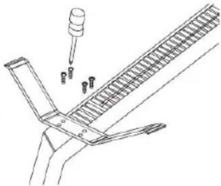
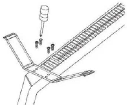
ASSEMBLY INSTRUCTION
| Model | L mm | H mm | L1 mm | H1 mm |
| 90-093 | 515 | 450 | 218 | 344 |
| 90-094 | 675 | 450 | 378 | 344 |
| 90-095 | 835 | 450 | 538 | 344 |
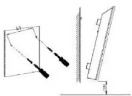
Feet Installation&removal
natural_image
Technical line drawing showing two mechanical components with alignment guides (no text or symbols)Wall mounted mode
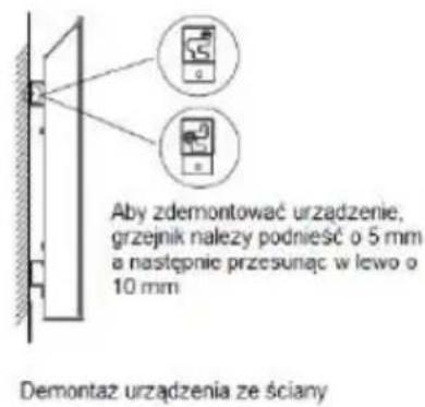
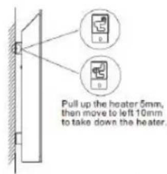
Take down the heater from wall
natural_image
Technical line drawing of a mechanical assembly with a pipette and multiple bolts (no text or symbols)Ceiling/Picture frame
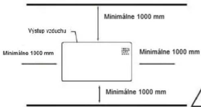
Floor
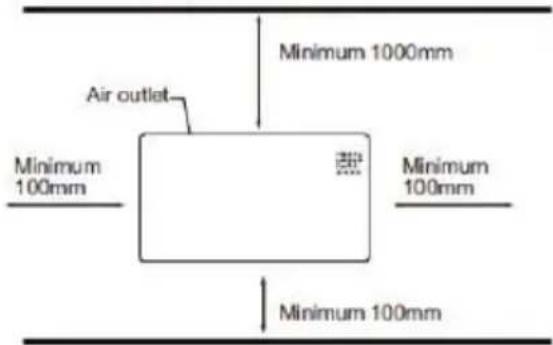
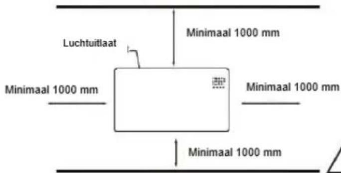
This heater MUST be installed to the minimum required distances at the four sides of the heater.
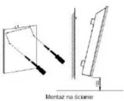
Unpack your package and find the heater together with the wall mounting accessories pack.
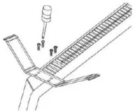
- Mark the positions of the four holes to be drilled on the wall, and Drill the holes with the drill bit. Make sure the distance between each holes is same as the round holes on the brackets at back of the heater.
-
Insert the plastic rails fitting into the holes.
-
Insert the metal screws into the plastic rails.
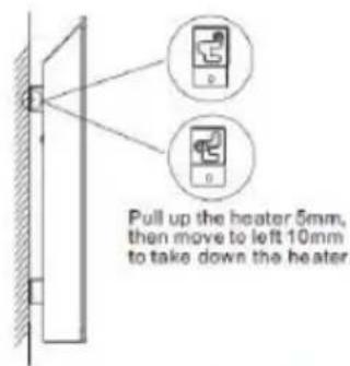
- Lift the heater and aim the round holes on the brackets at back of the heater to the screws on the wall and slide the heater 10mm to the right
- Make sure the distance between the bottom of the heater and the floor is no less than 10cm when the heater is installed
USING INSTRUCTIONS
Control panel/Remote control
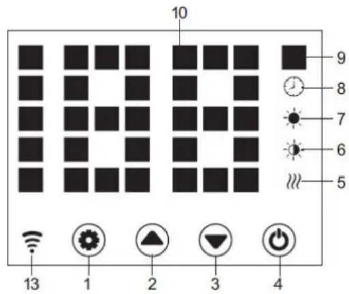
- Setting Button
- Up Button
- Down Button
- Power Button
- Heating Element Working Indicator
- Low Heating Indicator
-
High heating Indicator
-
Timer Indicator
- Temperature Indicator
- LED Number Display
- ECO function
- Low/High Heating Selection
- WiFi indicator (If connected OK, wifi indicator lights on; if failed)
Starting
- Take out the heater from the carton carefully. Please save the carton for off-season storage.
Make sure the power switch is in the OFF position before plugging it in. - Ensure the heater is fulyy assembled according to the Mounting Guide.
- It's better not to use the same electric outlet with other high wattage electrical appliances in order to avoid overloading you circuit.
Turn ON
Plug in and turn on power switch, heater is in stand-by with buttons 1/2/3/4 on. Press button 4, heater turns on, display shows current area temperature.
Plug in the unit and turn on its power switch, it is in standby mode and shows current time, with button light 1/2/3/4. on. But then button light 1/2/3 will disappear after 10s.
Temp. Setting
Press button 1, temp. indicator flashes and its setting is activated. By pressing buttons 2 and 3, we select desired temp. and save it. Heater is heating, display shows current temperature and button 5 lights on.
Press button 1, temp indicator flashes and its setting is activated. Press 2 or 3 to set the temperature and 1 to save it, or just leave it 5s, setting is saved automatically.
Press 2/3 on the remoter for required temp and save the setting by OK.
Setting Timer
Timer Start Heating Time
In off-heating mode, press 1 twice to set timer(0H to 24H), and 2&3 to set temperature. After setting, it shows area temperature. Indicator 8 lights on in timer period and off when timer ends, then heater starts heating at high level.
Timer Stop Heating Time
In heating mode( high or low level), press 1 twice to set timer and 2 3 to set temperature. After setting, it shows area temperature. Indicator 8 lights on in timer period and off when timer ends. Then heater stops heating.
High/Low Heat Setting
- In working mode, button 2 shifts between high heating and stop heating(indicator 7 lights on when high heating and off when off heating); 5 High/Low Heat Selection
- In working mode, button 3 runs between low heating and off heating(indicator 6 lights on when low heating and off when off heating);
- In working mode, button 12 shifts among Off/Low/High heating, 7 lights on in high heating, 6 light on in low heat, and no light on when off heating).
Child-lock Setting
Press both 2 and 3 for 3s, system is locked and no setting could be done. After 3 s, display shows again area temperature.
Methods to unlock:
Press both 2 and 3 for 3s, the unit is unlocked.
Display buttons activation
Normally display buttons light are off when unit is working, touch the panel area below temperature, they are on again.
ECO Function
Press both setting button 1 and 3 for 3s (or press button 11 on remote control), ECO function runs. In this mode, display shows only some indicators (depending on what setting shave been done before ECO)
Methods to lock ECO function
Press any button on display 2) Press ECO button 11 on remote control.
Switch the display between °C/F
Press the keys 1 & 2 (the two keys on the left) simultaneously for about 10 seconds.
Open-window Detection
If temperature decreases 3^ C or more in 2mins, open-window detection acts and, unit stops heating, indicator 9 flashes. Press button 4, turn off heater then turn on again open-window detection is closed.
WiFi Reset
In heating mode, press button 1 for 3s, WIFI is reset, with its indicator light on.
Turn off
Turn off switch 4, heater stops working, and turn off power supply, heater is power off.
WiFi and app operation:
- The heater should be used within the range of the Wi-Fi router.
NOTE The Wi-Fi router should operate at 2.4 GHz
-
Download the "TuyaSmart" application on smartphone, tablet or computer.
-
After installing the application, select "transfer".
-
To register, enter the email address to which the verification code will be sent. The code must be applied to the application within 60 seconds of receipt. Then create a password. Selecting "confirmation" completes the registration process in the application.
-
To add a new device, select "Add device".
-
Select "Small device" from the list and then "Thermostat".
After selecting the "Thermostat" option, the application will show information about the selected number of supported frequencies 2.4 GHz Wi-Fi Router, as well as a prompt to enter the Wi-Fi password if the control device is used before is not dependent on the range.
-
Connect the heater to the power supply.
-
Turn on the heater.
-
On the control panel, hold the "M" button, until the blue LED next to the Wi-Fi marking, will flash quickly. Then click "Next" in the application.
-
The application will show the options of "fast flashing" and "slow flashing". Select "fast flashing" or the application will search for the device itself after a while.
-
After establishing the connection between the application and the device, the name of the device will appear in the application. Select device selection, then the control panel will appear in the application.
-
The application is ready to control the radiator settings!
The "TuyaSmart" application allows the following settings:
- heating on and off (without operating the control panel power supply, which must be done manually using the main switch),
– thermostat temperature setting,
– timer setting,
- configuration of a weekly heating cycle.
You can control the heater remotely. If the radiator is within range of the paired Wi-Fi Router, the control application will work on the device with Internet access.
Application
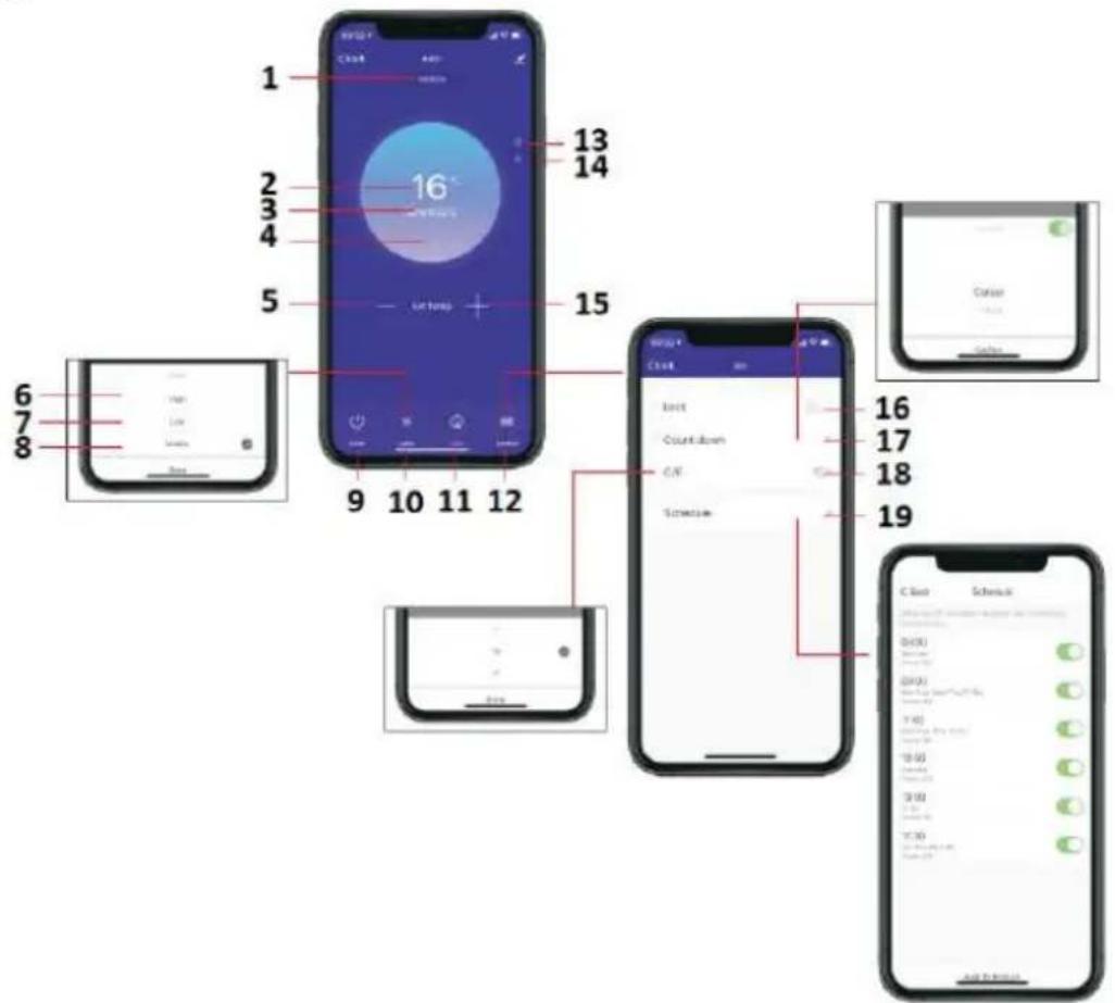
-
Heating level
-
Seting temperature
-
Area temperature
-
Heating
-
Decrease temperature
-
Hi
-
Lo
-
Mid
-
On/Off
-
Mode
-
Eco
-
Function
-
Child-lock
-
ECO
-
Increase temperature
-
Button child-lock
-
Button count down
-
°C/F
-
Schedule
BATTERY CHANGE
- To unlock battery, gently pull the latch open with the cover.
- Insert new CR2032 battery, note their required polarity (+/-)
- Close the battery cover so that the latch locks.
CLEANING AND MAINTANCE
Before cleaning your heater, switch off the heater and allow it to cool. Disconnect the electricity supply to the appliance. The outside can be cleaned by wiping it over with a soft damp cloth and then dried. Do not use abrasive cleaning powders or furniture polish, as this can damage the surface finish. To release the heater from the wall, for cleaning or redecoration, just open the screw bolt cap and unscrew the bolts to take off from the wall. For short term storage, just plug off the heater and leave it away; for long term storage, you can dismantle from the wall or cover it with some material.
TROUBLESHOOTING
If your heater fails to operate, please follow these instructions:
- Ensure that your circuit breaker or fuse is working properly.
- Be sure the heater is plugged in and that the electrical outlet is working properly.
- If the ON/OFF switch is not illuminated at ON position, send it to service center for reparation directly.
NOTE: IF YOU EXPERIENCE A PROBLEM WITH YOUR HEATER, PLEASE SEE THE WARRANTY INFORMATION FOR INSTRUCTIONS. PLEASE DO NOT ATTEMPT TO OPEN OR REPAIR THE HEATER YOURSELF. DOING SO MAY VOID THE WARRANTY AND COULD CAUSE DAMAGE OR PERSONAL INJURY. IF THE PROBLEM STILL PERSISTS, PLEASE CONTACT THE DISTRIBUTOR..
RECYCLING
Electrical equipment must not be disposed of household waste and, instead, should be utilized at appropriate facilities. Information on utilization can be provided by the product vendor or the local authorities. Waste electrical and electronic equipment contains substances that are not neutral to the natural environment. Equipment that is not recycled constitutes a potential hazard to the environment and to human health.
| Model identifier(s): 90-093 | |||||
| Item | Symbol | Value | Unit | Item | Unit |
| Heat output | Type of heat input, for electric storage local space heaters only (select one) | ||||
| Nominal heat output | P_nom | 1.0 | kW | Manual heat charge control with integrated thermostat | [no] |
| Minimum heat output (indicative) | P_min | 0.5 | kW | Manual heat charge control with room and/or outdoor temperature feedback | [no] |
| Maximum continuous heat output | P_max | 0.96 | kW | Electronic heat charge control with room and/or outdoor temperature feedback | [no] |
| Auxiliary electricity consumption | Fan assisted heat output | [no] | |||
| At nominal heat output | eI_max | 0.966 | kW | Type of heat output/room temperature control (select one) | |
| At minimum heat output | eI_min | 0.478 | kW | Single stage heat output and no room temperature control | [no] |
| In standby mode | eI_SB | 0.4 | W | Two or more manual stages, no room temperature control | [no] |
| With mechanic thermostat room temperature control | [no] | ||||
| With electronic room temperature control | [no] | ||||
| Electronic room temperature control plus day timer | [no] | ||||
| Electronic room temperature control plus week timer | [yes] | ||||
| Other control options (multiple selections possible) | |||||
| Room temperature control, with presence detection | [no] | ||||
| Room temperature control, with open window detection | [yes] | ||||
| With distance control option | [yes] | ||||
| With adaptive start control | [no] | ||||
| With working time limitation | [no] | ||||
| With black bulb sensor | [yes] | ||||
| Contact details: | Grupa Topex Sp. z o. o. Sp. k. Ul. Pograniczna 2/4, 02-285 Warszawa | ||||
| Remark:For electric local space heaters, the measured seasonal space heating energy efficiency ηs cannot be worse than the declared value at the nominal heat output of the unit. | |||||
| Model identifier(s): 90-094 | |||||
| Item | Symbol | Value | Unit | Item | Unit |
| Heat output | Type of heat input, for electric storage local space heaters only (select one) | ||||
| Nominal heat output | P_nom | 1.5 | kW | Manual heat charge control with integrated thermostat | [no] |
| Minimum heat output (indicative) | P_min | 0.75 | kW | Manual heat charge control with room and/or outdoor temperature feedback | [no] |
| Maximum continuous heat output | P_max | 1.48 | kW | Electronic heat charge control with room and/or outdoor temperature feedback | [no] |
| Auxiliary electricity consumption | [no] | ||||
| At nominal heat output | eI_max | 1.485 | kW | Type of heat output/room temperature control (select one) | |
| At minimum heat output | eI_min | 0.720 | kW | Single stage heat output and no room temperature control | [no] |
| In standby mode | eI_SB | 0.3 | W | Two or more manual stages, no room temperature control | [no] |
| With mechanic thermostat room temperature control | [no] | ||||
| With electronic room temperature control | [no] | ||||
| Electronic room temperature control plus day timer | [no] | ||||
| Electronic room temperature control plus week timer | [yes] | ||||
| Other control options (multiple selections possible) | |||||
| Room temperature control, with presence detection | [no] | ||||
| Room temperature control, with open window detection | [yes] | ||||
| With distance control option | [yes] | ||||
| With adaptive start control | [no] | ||||
| With working time limitation | [no] | ||||
| With black bulb sensor | [yes] | ||||
| Contact details: | Grupa Topex Sp. z o. o. Sp. k. Ul. Pograniczna 2/4, 02-285 Warszawa | ||||
| Remark:For electric local space heaters, the measured seasonal space heating energy efficiency ηs cannot be worse than the declared value at the nominal heat output of the unit. | |||||
| Model identifier(s): 90-095 | |||||
| Item | Symbol | Value | Unit | Item | Unit |
| Heat output | Type of heat input, for electric storage local space heaters only (select one) | ||||
| Nominal heat output | P_nom | 2.0 | kW | Manual heat charge control with integrated thermostat | [no] |
| Minimum heat output (indicative) | P_min | 1.0 | kW | Manual heat charge control with room and/or outdoor temperature feedback | [no] |
| Maximum continuous heat output | P_max | 1.98 | kW | Electronic heat charge control with room and/or outdoor temperature feedback | [no] |
| Auxiliary electricity consumption | [no] | ||||
| At nominal heat output | el_max | 1.985 | kW | Type of heat output/room temperature control (select one) | |
| At minimum heat output | el_min | 0.979 | kW | Single stage heat output and no room temperature control | [no] |
| In standby mode | el_SB | 0.4 | W | Two or more manual stages, no room temperature control | [no] |
| With mechanic thermostat room temperature control | [no] | ||||
| With electronic room temperature control | [no] | ||||
| Electronic room temperature control plus day timer | [no] | ||||
| Electronic room temperature control plus week timer | [yes] | ||||
| Other control options (multiple selections possible) | |||||
| Room temperature control, with presence detection | [no] | ||||
| Room temperature control, with open window detection | [yes] | ||||
| With distance control option | [yes] | ||||
| With adaptive start control | [no] | ||||
| With working time limitation | [no] | ||||
| With black bulb sensor | [yes] | ||||
| Contact details: | Grupa Topex Sp. z o. o. Sp. k. Ul. Pograniczna 2/4, 02-285 Warszawa | ||||
| Remark:For electric local space heaters, the measured seasonal space heating energy efficiency ηs cannot be worse than the declared value at the nominal heat output of the unit. | |||||
| Modell | Lmm | Hmm | L1mm | H1mm |
| 90-093 | 515 | 450 | 218 | 344 |
| 90-094 | 675 | 450 | 378 | 344 |
| 90-095 | 835 | 450 | 538 | 344 |
natural_image
Technical line drawing of a mechanical assembly with a pipette and bolts (no text or symbols)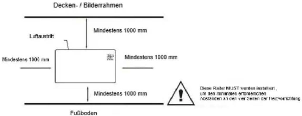
| Modell | Lmm | Hmm | L1mm | H1mm |
| 90-093 | 515 | 450 | 218 | 344 |
| 90-094 | 675 | 450 | 378 | 344 |
| 90-095 | 835 | 450 | 538 | 344 |
natural_image
Pure technical line drawing of a mechanical assembly with no text or symbolsnatural_image
Technical line drawing of a mechanical assembly with a pipette and multiple bolts (no text or symbols)| Model | Lmm | Hmm | L1mm | H1mm |
| 90-093 | 515 | 450 | 218 | 344 |
| 90-094 | 675 | 450 | 378 | 344 |
| 90-095 | 835 | 450 | 538 | 344 |
natural_image
Technical line drawing showing two views of a rectangular object with diagonal lines and a vertical wall, no text or symbols present.natural_image
Technical line drawing of a mechanical assembly with a pipette and multiple pins (no text or symbols)Floor
| Modelka | Lmm | Hmm | L1mm | H1mm |
| 90-093 | 515 | 450 | 218 | 344 |
| 90-094 | 675 | 450 | 378 | 344 |
| 90-095 | 835 | 450 | 538 | 344 |
natural_image
Technical line drawing showing two views of a mechanical component with dimension annotations (no text or symbols)Zed montáz režim
natural_image
Technical line drawing of a mechanical assembly with a pipette and multiple pins (no text or symbols)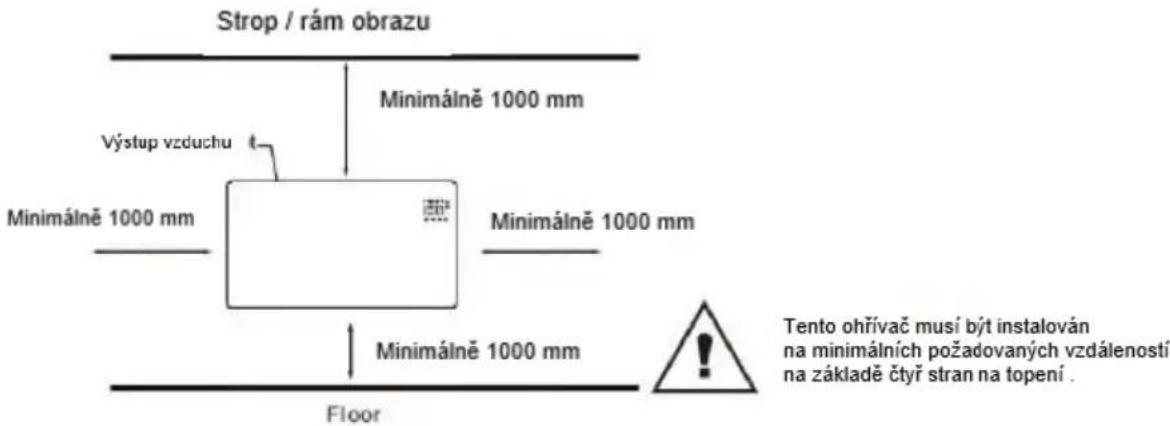
| Model | Lmm | Hmm | L1mm | H1mm |
| 90-093 | 515 | 450 | 218 | 344 |
| 90-094 | 675 | 450 | 378 | 344 |
| 90-095 | 835 | 450 | 538 | 344 |
natural_image
Technical line drawing showing two views of a mechanical component with alignment guides (no text or symbols)Múr montáž režim

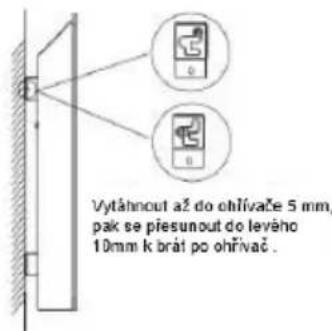
Vytiahnuf až do ohrievača 5 mm, potom sa presunúř do lavého 10mm k braf po ohrievač.
Zložte ohrievač zo steny
natural_image
Technical line drawing of a mechanical assembly with a pipette and multiple bolts (no text or symbols)Strop / rám obrazu
| Model | Lmm | Vmm | L1mm | V1mm |
| 90-093 | 515 | 450 | 218 | 344 |
| 90-094 | 675 | 450 | 378 | 344 |
| 90-095 | 835 | 450 | 538 | 344 |
Feet Installation&removal

natural_image
Pure technical line drawing of a mechanical or architectural component with no text, numbers, or symbolsWall mounted mode
Take down the heater from wall
natural_image
Technical line drawing of a mechanical assembly with a pipette and three small components (no text or symbols)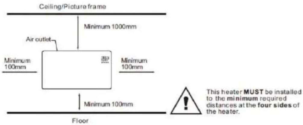
| Modelis | Lmm | Hmm | L1mm | H1mm |
| 90-093 | 515 | 450 | 218 | 344 |
| 90-094 | 675 | 450 | 378 | 344 |
| 90-095 | 835 | 450 | 538 | 344 |
natural_image
Technical line drawing of a mechanical assembly with a pipette and multiple bolts (no text or symbols)| Modelis | Lmm | Hmm | L1mm | H1mm |
| 90-093 | 515.lpp | 450 | 218.lpp | 344.lpp |
| 90-094 | 675 | 450 | 378.lpp | 344.lpp |
| 90-095 | 835.lpp | 450 | 538 | 344.lpp |
natural_image
Pure technical line drawing of a mechanical or optical setup with no text, numbers, or symbolsnatural_image
Technical line drawing of a mechanical assembly with a pipette and multiple bolts (no text or symbols)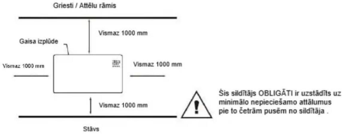
| Modello | Lmm | Hmm | L1mm | H1mm |
| 90-093 | 515 | 450 | 218 | 344 |
| 90-094 | 675 | 450 | 378 | 344 |
| 90-095 | 835 | 450 | 538 | 344 |
natural_image
Technical line drawing showing two views of a mechanical component with no visible text or symbolsnatural_image
Technical line drawing of a mechanical assembly with a pipette and multiple bolts (no text or symbols)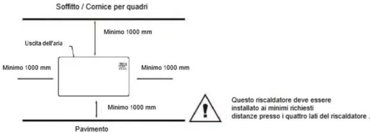
Timer Stop Heating Time
RACCOLTA DIFFERENZIATA
| Model | Lmm | Hmm | L1mm | H1mm |
| 90-093 | 515 | 450 | 218 | 344 |
| 90-094 | 675 | 450 | 378 | 344 |
| 90-095 | 835 | 450 | 538 | 344 |
natural_image
Technical line drawing showing two views of a tilted rectangular object with diagonal lines and a vertical guide (no text or symbols)natural_image
Technical line drawing of a mechanical assembly with a pipette and three small components (no text or symbols)Plafond / fotolijst
Verdieping
- DETAILED SAFETY REGULATIONS
- ATTENTION!
- WARNING!
- When using electrical appliance basic precautions should always be followed including below:
- PACKING LIST
- ASSEMBLY INSTRUCTION
- Starting
- Turn ON
- Temp. Setting
- Setting Timer
- High/Low Heat Setting
- Child-lock Setting
- Display buttons activation
- ECO Function
- Switch the display between °C/F
- Open-window Detection
- WiFi Reset
- Turn off
- WiFi and app operation:
- NOTE The Wi-Fi router should operate at 2.4 GHz
- The "TuyaSmart" application allows the following settings:
- BATTERY CHANGE
- CLEANING AND MAINTANCE
- TROUBLESHOOTING
- RACCOLTA DIFFERENZIATA
Brand : NEO tools
Model : 90-095
Category : Heating