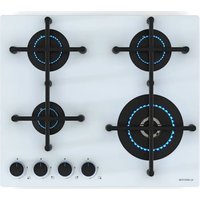
Illuminosa 4 - Cooker Klarstein - Free user manual and instructions
Find the device manual for free Illuminosa 4 Klarstein in PDF.


User questions about Illuminosa 4 Klarstein
0 question about this device. Answer the ones you know or ask your own.
Ask a new question about this device
Download the instructions for your Cooker in PDF format for free! Find your manual Illuminosa 4 - Klarstein and take your electronic device back in hand. On this page are published all the documents necessary for the use of your device. Illuminosa 4 by Klarstein.
USER MANUAL Illuminosa 4 Klarstein
text_image
COOKINGCO COOKINGCO KINGCOOKING KINGCOOKING COOKINGCO KINGCOOKING KINGCOOKING KINGCOOKINGKLARSTEIN
www.klarstein.com

area
| Category | Value | | -------- | ----- | | A | 100 | | B | 100 | | C | 100 | | D | 100 |text_image
QR code image containing encoded data, no visible human-readable textINHALTSVERZEICHNIS
Technische Daten 2
text_image
Technical diagram of a four-cylinder electrical switch with numbered components for identification.text_image
Technical diagram of a gas stove with numbered components for identificationnatural_image
Technical line drawing of a mechanical component with circular holes and wiring (no text or symbols)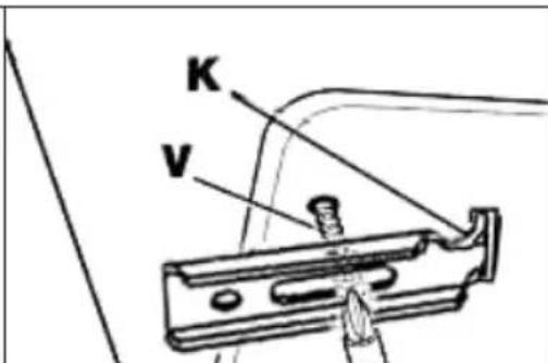
text_image
K Vnatural_image
Technical line drawing of mechanical components with no visible text or symbolsAbbildung 8
natural_image
Symbol of a trash bin crossed with a diagonal line, no text or numbers presentBerlin Brands Group UK Limited
PO Box 42
272 Kensington High Street
London, W8 6ND
United Kingdom
EU-PRODUKTDATENBLATT
Congratulations on purchasing this device. Please read the following instructions carefully and follow them to prevent possible damages. We assume no liability for damage caused by disregard of the instructions and improper use. Scan the QR code to get access to the latest user manual and more product information.

text_image
QR code image containing encoded data, no visible human-readable textCONTENTS
Technical Data 32
Safety Instructions 34
Device Overview 37
Installation (Installer) 40
Gas Connection (Installer) 46
Adjusting the Appliance (Installer) 47
Conversion of the Appliance (Installer) 48
Maintenance (Installer) 48
Disassembly (Installer) 49
Operation 49
Cleaning and Care 52
Troubleshooting 53
Disposal Considerations 53
Manufacturer & Importer (UK) 53
EU Product Data Sheet 54
TECHNICAL DATA
| Item number | 10035464, 10035465, 10039896, 10046704, 10046705, 10046706, 10046707 |
| Power supply 220-240 V ~ 50/60 Hz |
| Item number | 10035464, 10046704, 10046706 | ||||
| PIN 2531DP-0053 | |||||
| Burners Gas types Pressures Injectors | diameter | Heat Inputs | |||
| No. | Denomination mb | ar 1/100 mm kW | |||
| 1 Wok | G30 (Butane) 28 | -30 100 4.0 | |||
| G30 (Butane) 50 | 78 4.0 | ||||
| G20 (Natural) 20 | 1 | 50 4.0 | |||
| 2 | Rapid (R) | - | - | - | - |
| 3 | Semi-Rapid (SR) | G30 (Butane) 28 | -30 | 65 1.75 | |
| G30 (Butane) 50 | 58 1.75 | ||||
| G20 (Natural) 20 | 97 1.75 | ||||
| 4 Auxiliary (Aux) | G30 (Butane) 28 | -30 | 50 1.0 | ||
| G30 (Butane) 50 | 43 1.0 | ||||
| G20 (Natural) 20 | 72 1.0 | ||||
| Item number 10035465, 10046705, 10046707 | |||||
| PIN 2531DP-0053 | |||||
| Burners Gas types Pressures Injectors | diameter | Heat Inputs | |||
| No. | Denomination mbar 1/100 mm kW | ||||
| 1 Wok | G30 (Butane) 28-30 100 4.0 | ||||
| G30 (Butane) 50 78 4.0 | |||||
| G20 (Natural) 20 150 4.0 | |||||
| 2 Rapid (R) | G30 (Butane) 28-30 | 85 3.0 | |||
| G30 (Butane) 50 75 3.0 | |||||
| G20 (Natural) 20 115 3.0 | |||||
| 3 | Semi-Rapid (SR) | G30 (Butane) 28-30 | 65 1.75 | ||
| G30 (Butane) 50 58 1.75 | |||||
| G20 (Natural) 20 97 1.75 | |||||
| 4 Auxiliary (Aux) | G30 (Butane) 28-30 | 50 1.0 | |||
| G30 (Butane) 50 43 1.0 | |||||
| G20 (Natural) 20 72 1.0 | |||||
| Item number 10039896 | |||||
| PIN 2531DP-0053 | |||||
| Burners Gas types Pressures Injectors | diameter | Heat Inputs | |||
| No. | Denomination mbar 1/100 mm kW | ||||
| 1 | Wok | - | - | - | - |
| 2 | Rapid (R) | G30 (Butane) 28-30 | 85 3,0 | ||
| G30 (Butane) 50 75 3,0 | |||||
| G20 (Natural) 20 115 3,0 | |||||
| 3 | Semi-Rapid (SR) | - | - | - | - |
| 4 | Auxiliary (Aux) | G30 (Butane) 28-30 | 50 1,0 | ||
| G30 (Butane) 50 43 1,0 | |||||
| G20 (Natural) 20 72 1,0 | |||||
SAFETY INSTRUCTIONS
Please take the time to read this instruction manual before installing or using the appliance. This instruction booklet must be kept with the appliance for any future reference. If the appliance is sold or transferred to another person, ensure the booklet is passed on to the new user.
- This appliance shall be installed in accordance with regulations in force and only used in a well ventilated space.
- Prior to installation, ensure that the gas and electrical supply complies with the type stated on the rating plate.
- Where this appliance is installed in marine craft or in caravans, it should not be used as a space heater.
- The gas pipe and electrical cable must be installed in such a way that they do not touch any parts or the appliance.
- The installation, adjustment, conversions and maintenance of the appliance must only be carried out by a qualified technician or installer.
- The adjustment conditions for this appliance are stated on the label or data plate.
- When installing gas appliances, the national standards and norms must be observed and complied with.
- The electrical safety of this appliance is only guaranteed if it is correctly connected to a good earth system, as prescribed by the electrical safety standards. The manufacturer declines all responsibility if these instructions are not followed. Contact customer service if you have any questions.
- The manufacturer cannot be held responsible for any damage to persons or things deriving from an incorrect installation of the appliance.
- Remove all packaging before using the appliance.
- The packaging materials used (cardboard, bags, polystyrene foam, nails, etc.) must not be left anywhere in easy reach of children because they are a potential hazard source.
- After unpacking the appliance, make sure the appliance and the power cord is not damaged. If the power cord is damaged, it must be replaced by the manufacturer, costumer service or similarly qualified personnel to prevent hazards.
- Contact customer service or similarly qualified personnel for repairs and adjustments to the appliance. Original spare parts and optional accessories can be purchased from customer service or authorized dealers.
- This appliance may only be used for its intended purpose. This appliance is intended for domestic cooking only. It is not designed for commercial or industrial purposes. Any other use is considered improper and dangerous.
- The adjacent furniture and all materials used in the installation must be able to withstand a minimum temperature of 85 °C above the ambient temperature of the room it is located in, whilst in use.
- In the event of burner flames being accidentally extinguished, turn off the burner control and do not attempt to re-ignite the burner for at least one minute.
- The use of a gas cooking appliance results in the production of heat and moisture in the room in which it is installed. Ensure that the kitchen is well ventilated: keep natural ventilation holes open or install a mechanical ventilation device (mechanical extractor hood).
- Prolonged intensive use of the appliance may call for additional ventilation, for example opening of a window, or more effective ventilation, for example increasing he level of mechanical ventilation where present.
- Keep children near the appliance under supervision. Do not allow children to play near or with the appliance.
- The appliance gets hot when it is in use.
- Children should be kept away from the appliance until it has cooled down.
• This appliance is for use by adults only.
- Children can also injure themselves by pulling pans or pots off the appliance.
- This appliance can be used by children aged from 8 years and above and persons with reduced physical, sensory or mental capabilities or lack of experience and knowledge if they have been given supervision or instruction concerning use of the appliance in a safe way and understand the hazards involved.
- Cleaning and user maintenance shall not be made by children without supervision.
- Only use the appliance for preparing food.
- Do not modify this appliance. Burner panel is not designed to operate from an external timer or separate remote control system.
- Never use the appliance if it has come into contact with water.
- The heating and cooking surfaces of the appliance become hot when they are in use, take all due precautions.
- Do not use large cloths, tea towels or similar as the ends could touch the flames and catch fire.
- Never leave the appliance unattended when cooking.
- Unstable or misshapen pans should not be used on the appliance as they can cause an accident by tipping or spillage.
- Do not use or store flammable materials in the storage drawer near this appliance.
- Perishable food, plastic items and aerosols may be affected by heat and should not stored above or below the appliance.
- Do not spray aerosols in the vicinity of this appliance while it is in operation.
- Use heat-resistant pot holders or gloves when handling hot pots and pans.
- Do not let pot holders come near open flames when lifting cookware.
• Take care not to let pot holders or gloves get damp or wet, as this causes heat to transfer through the material quicker with the risk of burning yourself.
- Only ever use the burners after placing pots and pans on them. Do not heat up any empty pots or pans.
- Never use plastic or aluminium foil dishes on the appliance.
- When using other electrical appliances, ensure the cable does not come into contact with the appliance surfaces of the cooking appliance.
- If you have any mechanical parts eg. an artificial heart in your body, consult a doctor before using the appliance.
- Do not use a tea towel or similar materials in place of a pot holder. Such cloths can catch fire on a hot burner.
- When using glass cookware, make sure it is designed for top plate cooking. If the surface is made of glass-cracked, switch off the appliance to avoid defeat electrocution.
- To minimise the possibility of burns, ignition of flammable materials and spillage, turn cookware handles toward the side or centre of the top plate without extending over adjacent burners.
• Always turn burner controls off before removing cookware.
- Carefully watch foods being fried at a high flame setting.
• Always heat fat slowly and watch as it heats.
- Foods for frying should be as dry as possible. Frost on frozen foods or moisture on fresh foods can cause hot fat to bubble up and over the sides of the pan.
- Never try to move a pan of hot fat, especially a deep fat fryer. Wait until the fat is completely cool.
- Ensure the control knobs are in the "Off" position when the appliance is not in use.
Special instructions for the use of electrical appliances
- Do not touch the appliance if your hands or feet are wet or damp.
- Do not use the appliance bear footed.
- Do not pull on the power cord to unplug the power cord from the socket.
- Do not leave the appliance outdoors under the sun, rain, etc.
- Do not let children or anybody who is incapable to use the appliance on their own to get near the appliance.
- If you are using a socket near the appliance make sure that the cables of electrical appliances you are using do not touch it and are far enough away from all hot parts of the appliance.
- When you have finished using the appliance check that all the controls are in the "OFF" or closed position.
- Unplug the power cord from the wall outlet before you start cleaning or servicing the appliance.
- In the event of a failure and/or malfunction, turn off the appliance immediately and unplug the power cord from the wall outlet. Never attempt to repair the appliance yourself. Contact customer service or similarly qualified personnel. Keep all the information on the nameplate of the appliance at hand.
- When an appliance is out of service, no longer in use or is to be disposed of, it must be rendered unusable (for example, the power cord should be removed, etc.). In particular, remove any parts that could pose a danger to children, for example when playing.
DEVICE OVERVIEW
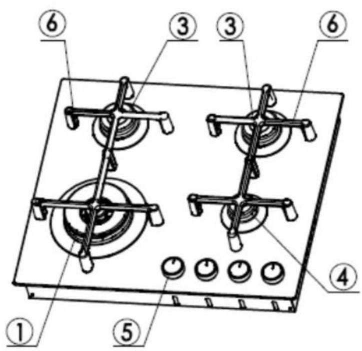
Item number 10035464, 10046704, 10046706
text_image
Technical diagram of a gas stove with numbered components for identification| 1 Wok gas burner 5 Gas burner control knob | ||
| 3 Semi-Rapid gas burner (SR) 6 Pan support for burners | ||
| 4 Auxiliary gas burner (Aux) |
Note: Pan supports are the same in shape. Pay attention to put them in proper position, according to the burners' diameter!
| Item number 10035465, 10046705, 10046707 | |||
| 1 Wok gas burner 4 Auxiliary gas burner (Aux) | |||
| 2 Rapid gas burner (R) 5 Gas burner control knob | |||
| 3 Semi-Rapid gas burner (SR) 6 Pan support for burners |
Note: Pan supports are the same in shape. Pay attention to put them in proper position, according to the burners' diameter!
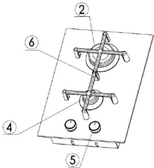
Item number 10039896
text_image
Technical diagram of a gas stove or heating unit with numbered components labeled 2, 4, 5, and 6.2 Rapid gas burner (R) 5 Gas burner control knob
4 Auxiliary gas burner (Aux) 6 Pan support for burners
Note: Pan supports are the same in shape. Pay attention to put them in proper position, according to the burners' diameter!
INSTALLATION (INSTALLER)
Technical information
- The installation, the adjustments, conversions and maintenance of the appliance must only be carried out by a qualified technician or installer. The manufacturer cannot be held responsible for any damage to persons or things deriving from an incorrect installation of the appliance.
- The safety and adjustment devices of the appliances may, during their life, only be modified by the manufacturer or duly authorised supplier.
- All-gas appliances can be installed as "Class 3" (fitted) in compliance with gas standards only.
- Any side walls (one only – left or right) that overcome in height the work top, have to be 50 mm far at least.
- The adhesive used to join the laminated plastic to the piece of furniture must be able to withstand a temperature of at least 150^ , so the laminated plastic will not come unstuck.
- The installation of all-gas appliances must comply with the National Rules in force.
- This appliance is not connected to a flue for discharge of the combustion products. Therefore, it must be connected in compliance with the above mentioned installation rules. Particular attention must be paid to the instructions given below for ventilation and aeration.
Ventilating the rooms
The room, where the appliance is installed, must be permanently ventilated so as to guarantee correct functioning according to the National Rules in force. The quantity of air needed is that required for a regular combustion of the gas and for the ventilation of the room and whose volume must be no less than 20 m^3 . The natural flow of air must be direct through permanent openings in the walls (that go through to the outside) of the room to be ventilated with a minimum cross free section of 100 cm^2 for appliance fitted with the Flame Safety Device (FSD) on each burner (see figure 1). These openings must be positioned so they cannot be ever obstructed. If the appliance is not fitted with the Flame Safety Device (FSD) on each burner, the cross free section shall be not less than 200 cm^2 .
Indirect ventilation is also allowed by taking air from rooms adjacent to the one to be ventilated, strictly complying with the prescriptions of the National Rules in force.
Location and aeration
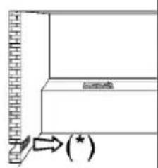
Gas appliances must always discharge the products of combustion through extractors connected to flues or directly to the outside (see figure 2). If it is impossible to use an extractor, a fan installed on the window or on a wall facing the outside is allowed and should be switched on each time the appliance is used (see figure 3), provided the rules and regulations in force relating to ventilation.
(*) Air inlet: minimum section 100 cm ^2
text_image
Diagram showing a mechanical or structural component with an arrow and a label (*) indicating a specific point.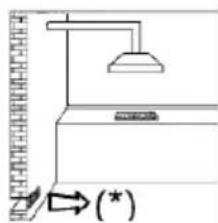
natural_image
Simple line drawing of a ceiling lamp and wall-mounted fixture with an arrow indicating rotation (no text or symbols)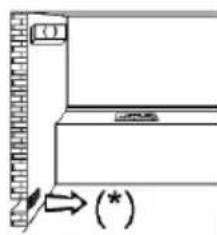
natural_image
Simple line drawing of a door with a wall-mounted sensor and an arrow pointing to a star (no text or symbols)Figure 1 Figure 2 Figure 3
Note: When a gas appliance is being used it produces heat and humidity in the room where it is installed. For this reason the room must be well ventilated, keeping the natural ventilation openings free (see figure 1) and switching on the mechanical aeration system (suction hood or electric fan – see figures 2 and 3).
If the cooker is used for a long time additional aeration may be necessary, for instance, opening a window or a more effective aeration by increasing the power of the mechanical system if there is one.
Unpacking the appliance
Once the outer wrapping and the inner wrappings of the various parts have been removed, check and make sure that the appliance is in perfect condition. If you have any doubts, do not use the appliance and contact customer service.
Some parts are mounted on the appliance and protected by a plastic film. This protective film must be removed before ever the appliance is used. We recommend slitting the plastic film along the edges with a sharp knife or pin.

CAUTION
Risk of suffocation and injury for children! The packaging materials used (cardboard, bags, polystyrene foam, nails ...) should not be left anywhere within easy reach of children as they are a potential hazard source.
Installing and fixing the hob
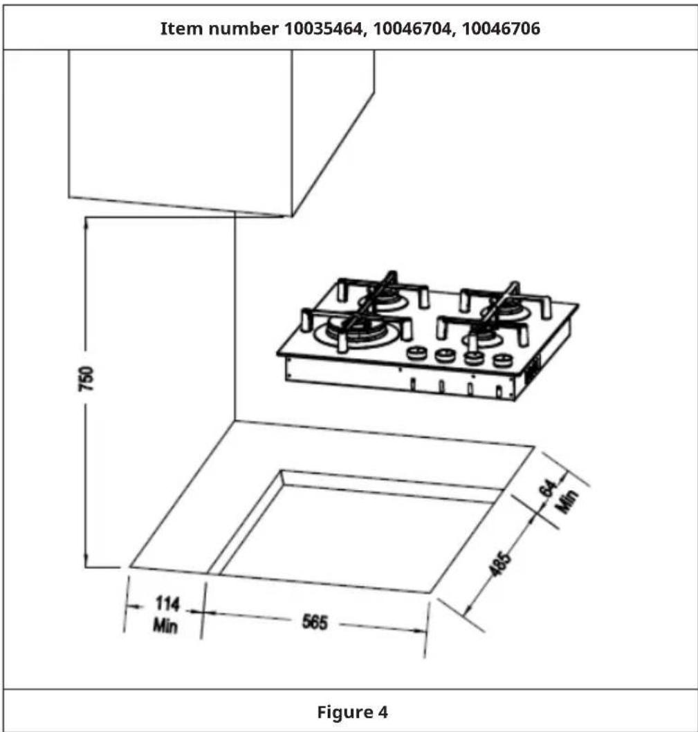
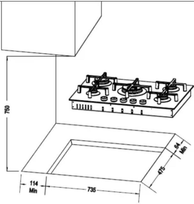
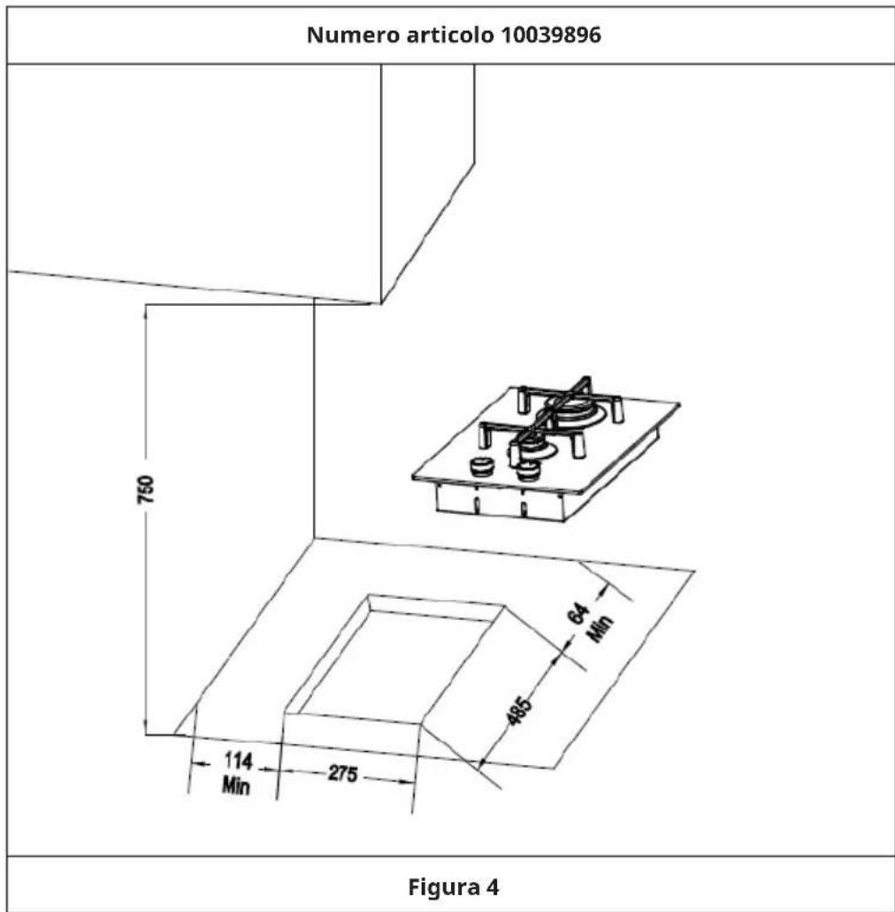
The measurements of the cavity made in the top of the modular cabinet and into which the hob will be recessed are indicated in figure 4. Cupboards or hoods have to maintain a least distance of 750 mm from the top.
text_image
Item number 10035464, 10046704, 10046706 750 64 Min 485 114 Min 565 Figure 4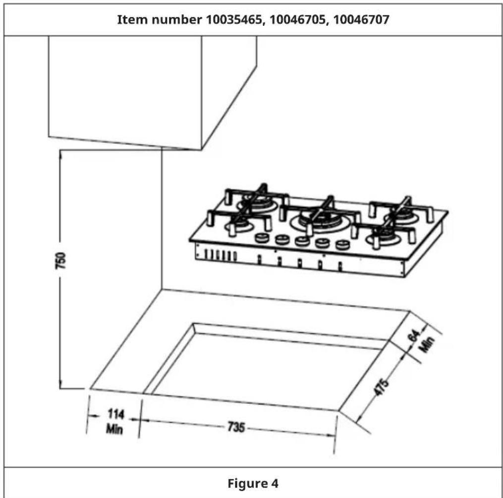
other
| Item Number | Dimension (Width) | | ----------- | ----------------- | | Item number 1 | 10035465, 10046705, 10046707 | | Item number 2 | 750 | | Item number 3 | 64 Min | | Item number 4 | 475 | | Item number 5 | 114 Min | | Item number 6 | 735 | | Item number 7 | - | Figure 4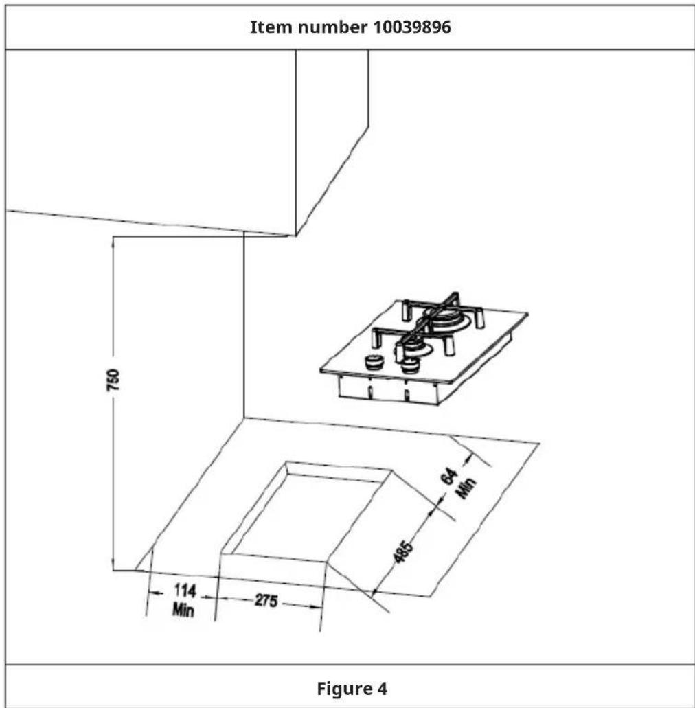
other
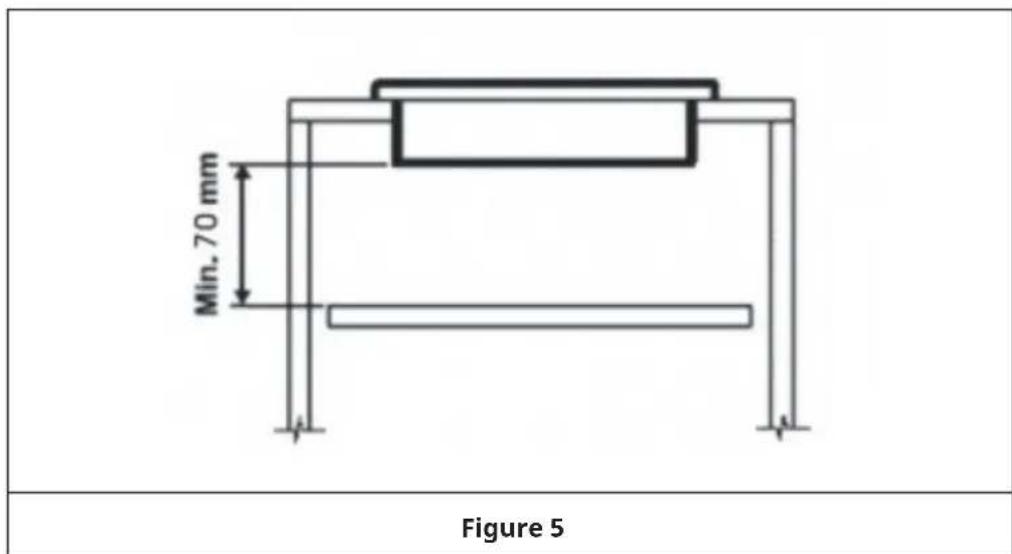
| Component | Dimension | | --------- | --------- | | Top Panel | 750 | | Inner Wall | 64 Min | | Outer Wall | 485 | | Bottom Panel | 114 Min | | Bottom Panel | 275 | | Figure 4 (top) | - | | Figure 4 (bottom) | - |Important note: Under the hob it is necessary to always apply a panel of separation in wood, positioned to a least distance of 70 mm by the bottom of the same, which has to easily be removable to allow possible operations of maintenance (see figure 5).
text_image
Min. 70 mm Figure 5Sealing the hob
The hob has a special seal which prevents liquid from infiltrating into the cabinet. Strictly comply with the following instructions in order to correctly apply this seal:
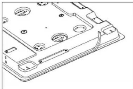
- Back board of the reverse side' edge use the foam-rubber cushion to paste a round (see figure 6).
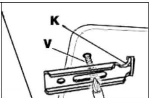
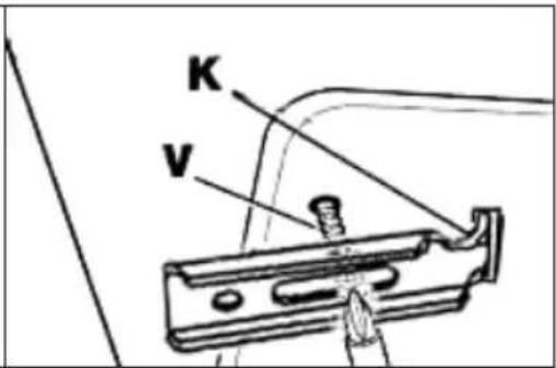
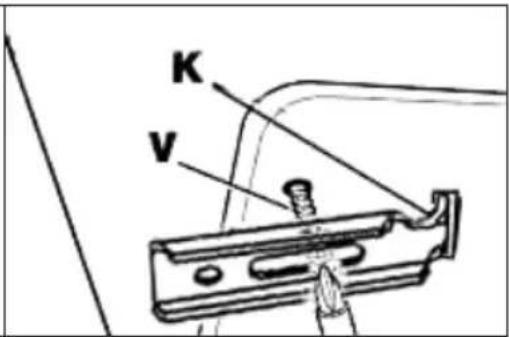
• Evenly and securely fix the seal to the hob, pressing it in place with the fingers. - Remove the strip of protective paper from the seal. Insert the hooks into their relative housings (K) on the hob and set this into the hole in the cabinet. Lock it in place with the relative fixing screws (V) (see figure 7).
- Put the pan support on the mark of top plate (see figure 8).
natural_image
Technical line drawing of a mechanical component with circular holes and attached parts (no text or symbols)Figure 6 Figure 7
text_image
K V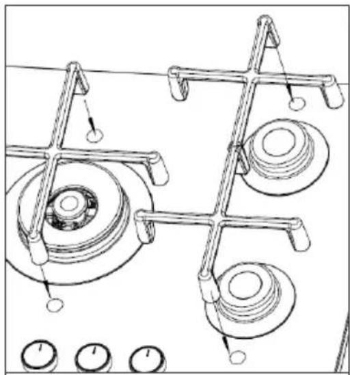
natural_image
Technical line drawing of a mechanical assembly with gears and rods (no text or symbols)Figure 8
GAS CONNECTION (INSTALLER)
Note: The installation, the adjustments, conversions and maintenance of the appliance must only be carried out by a qualified technician or installer. Do not connect the appliance to the gas supply yourself!
Important notes on gas connection
- Before to connect the appliance to the gas network, check that the adjustment sticker data plate, put on the bottom of the appliance, correspond to the available one in the gas network. The adjustment sticker data plate, gives all the appliance's setting conditions as: gas type and gas operating pressures.
- Once installed, check there are no leaks using a soapy solution only. Never use a flame! It is forbidden!
When gas is distributed through ducts the appliance must be connected to the gas mains with:
- A flexible stainless steel, seamless pipe in accordance with the National Rules in force, with a maximum 2 metres extension and seals in accordance with the National Rules in force. Make sure that the pipe, once the appliance is installed, does not come into contact with the mobile parts of the unit in which the hob is built-in (like drawers for instance), get squashed or is too bent.
- A rigid steel pipe in accordance with the National Rules in force, whose joints must be made using, threaded fittings in accordance with the Standard ISO 7/1. The use of hemp with suitable adhesives or Teflon tape as a sealant is not allowed.
- A copper pipe in accordance with the National Rules in force, whose joints must be made using sealed fittings in accordance with the National Rules in force.
When gas is supplied directly from a gas cylinder, the appliance, supplied by a pressure regulator must be connected:
- With flexible stainless steel, seamless pipes in accordance with the National Rules in force with a maximum 2 metres extension and seals in accordance with National Rules in force. Make sure that the pipe does not come into contact with the mobile parts of the unit in which the hob is built-in (like drawers for instance), get squashed or is too bent. We recommend attaching the special adapter to the flexible pipe, easily found on the market, to facilitate connection to the pressure regulator's hose fitting on the cylinder.
Anyway, the pipe connecting the appliance with the gas mains should lie with smooth bends, and the rubber gasket preventing leakage added by user between the appliance's gas inlet fitting and the pipe connection must comply with the Standard EN 549 (available in specialized shops).

CAUTION
Risk of material damage and personal injury! Carry out the connection avoiding all kinds of stress to the appliance.
ADJUSTING THE APPLIANCE (INSTALLER)
- Check the adjustment of the appliance, before to make any adjusting operation, having a look on proper adjustment sticker data plate, put on the bottom of the appliance.
- Before any adjustment is attempted, which may be necessary when installing for the first time or when converting gas type, take the plug out of the mains socket.
- When the adjustment or preadjustment has been made, a technician must do any re-sealing, if any.
- To adjust “reduce rate”, using proper screw driver, from Natural gas to Butane/Propane ones, light burners one by one and put handle in minimum position (little flame). Remove the handle and screw clockwise completely the by-pass screw. Put back in position the handle and check stability flame, turning the handle from “Maximum” position (big flame) to “Minimum” position (little flame) and vice-versa.
- To adjust “reduce rate”, using proper screw driver, from Butane/Propane gases to Natural one, light burners one by one and put handle in minimum position (little flame). Remove the handle and unscrew anclockwise in the way to get proper flame. Put back in position the handle and check stability flame, turning the handle from “Maximum” position (big flame) to “Minimum” position (little flame) and vice-versa.
- "Primary air adjustment" on hob gas burners is unnecessary.
Adjusting gas taps
The adjustment of the reduced rate position is as follows:
- Light the burner and turn the knob to reduced rate position (little flame).
- Remove the knob which is simply inserted onto tap stem.
- Insert a small screwdriver into the top shaft and turn the throttling screw left or right until flame of the burner is conveniently regulated to the low position.
- In the case of taps with safety thermocouples, the adjustment screw is on the side of the stem.
- Make sure that when turning quickly from "Maximum" position to "Minimum" position, the burner does not extinguish.
Note: If the tap, after long use of the hob, presents some friction to rotation, do not insist to use it. Contact customer service to have the tap substituted with the proper one.
CONVERSION OF THE APPLIANCE (INSTALLER)
Changing the injectors
- The burners can be adapted to different types of gas by simply installing the injectors suitable for the gas you want to use. The “kit injectors” can be supplied together with the appliance or purchased.
- To do this, first remove the burner cups and with a socket spanner, unscrew injectors using proper tool and replace them with injectors corresponding to the new adjustment gas type. Always tightly lock the injector in place, without adding any material on the injector's threads: It is forbidden!
- To help the installer, there is a table in the “Technical Data” section giving nominal heat input, injector diameter and operating pressures of the different types of gas. For best comprehension, each injector is marked on its body with proper diameter.
• After the injectors have been changed, the technician must adjust the burners as described in the previous paragraphs. Seal any adjustment or preadjustment parts.
Important note: After the conversion, substitute the adjustment sticker data plate put on the bottom of the appliance with the new one, corresponding to the new gas adjustment. The sticker is included in the "kit injectors".
MAINTENANCE (INSTALLER)
Note: Prior to any maintenance work or before changing parts, disconnect the appliance from the gas and electricity power sources.
Replacing components
- To access the terminal board and the power cable, it is necessary to remove the hob from the cabinet by unscrewing the relative fixing screws (V) (see figure 7).
- If the power cord needs to be replaced, contact customer service or a similarly qualified person as it is necessary to use special utensils. The technician will have to connect a cable with a suitable cross section keeping the earth wire longer than the phase wires.
- To replace other gas and electrical components, that are lodged inside the hob, it is enough to remove the work top unscrewing the fixing screws of the burners.
- Replace the seal each time you change a tap in order to guarantee a perfect tightness between body and rail.
DISASSEMBLY (INSTALLER)
Note: Installation/assembly and disassembly of the unit must only be carried out by qualified personnel.
Before dismantling, any gas in the unit must be vented. Proceed as follows:
- Close all supply valves, but do not disconnect the gas cooker from the line yet.
- Now light all the burners. The remaining gas contained in the appliance burns off in a short time.
- After that, the appliance's pipes are free of gas and the gas cooker can be disconnected from the connections.
Important notes on dismantling the unit
- The disassembly is the same as the installation/assembly in the reverse order of the steps.
- Have a second person help you during disassembly to avoid injury.
- Ensure sufficient ventilation of the working area during disassembly.
- There are no motors or accumulators in this gas hob. Observe the section "Disposal Considerations".
OPERATION
Important notes on operation
- When the burners or plates are in use do not leave them unattended and make sure there are no small children in the vicinity. Check that pan handles are positioned correctly and always keep an eye on the pan whenever oils or fats are used as they are easily inflammable.
- Do not use spray cans near the appliance when it is in use.
- If the built-in hob has a lid, before opening the lid remove any food deposits from its surface.
- If the built-in hob has a crystal glass lid, it can explode if heated. Turn in "Off" position all the burners and switch off all plates. Let the hob become cool before closing the lid.
- If you see any cracks on the surface of the plate, disconnect the appliance from the mains immediately.
- After you have used the appliance make sure that all the controls are in "Off" position.
Gas burners
• The burners are graduated in their size and rating to provide the exact heat required for every style of cooking.
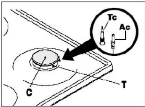
• The burners can be equipped with Flame Safety Device (FSD = Thermocouple, see figure 5).
- On the top of each knob there is a printed diagram showing to which burner or heating element it refers.
text_image
Tc Ac C TFigure 9
Manual ignition
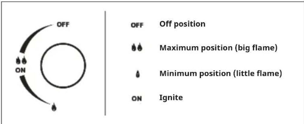
- Press and turn clockwise the knob corresponding to the burner you wish to use from "Off" position, until it reaches the "Maximum" position (corresponding to the big flame, see figure 10) and place a lighted match close to the burner.
- After ignition, turn the handle from "Maximum" position (corresponding to the big flame) to "Minimum" position (corresponding to the little flame) and check the stability of the flame. To turn the burner off, turn clockwise the handle up to "Off" position.
text_image
OFF OFF Off position Maximum position (big flame) Minimum position (little flame) ON IgniteFigure 10
Automatic electrical ignition (only certain versions, see figure 9, ref. Ac)
- The command of lighting is integrated in the control knob. Press and turn anclockwise the knob corresponding to the burner you wish to use from "Off" position, until it reaches the "Maximum" position (see figure 10) corresponding to the big flame. Automatically the ignition spark shoots. Keep the knob pressed until flame ignition. Matches can be used to light the burners in a blackout.
- After ignition, turn the handle from "Maximum" position (corresponding to the big flame) to "Minimum" position (corresponding to the little flame) and check the stability of the flame. To turn the burner off, turn clockwise the handle up to "Off" position.
Lighting of burners equipped with safety thermocouples (only certain versions, see figure 9, ref. Tc)
- In case burners are fitted with Flame Safety Device (FSD = Thermocouple, figure 9, Tc), repeat operations described previously.
- Once the flame is alight, keep the knob pressed for about 10 seconds to allow the Flame Safety Device (FSD = Thermocouple) to warm up. If, at the end of this time, the burner fails to alight, it means that Flame Safety Device (FSD = Thermocouple) is not sufficiency heated. Repeat the operation.
Optimum use of the burners
To get the maximum yield with the minimum consumption of gas it is handy to keep the following points in mind:
- Once the burner has been alighted, adjust the flame according to your needs, from "Maximum" position (big flame) to "Minimum" position (little flame).
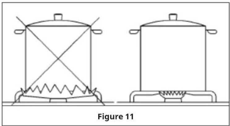
- Use proper pan size (with flat bottom only) for each burner (see the table below and figure 11).
- When the contents of the pan start boiling, turn the knob down to the "Minimum" position with reduced rate (small flame).
• Always put a lid on the pan.
natural_image
Line drawing of two identical cooking pots with heating elements, labeled Figure 11 (no text or symbols on the pots themselves)| Pan diameter (∅ in cm) | ||||
| Item number | Wok Rapid | Semi-Rapid Auxiliary | ||
| 10035464, 10046704, 10046706 | 24-26 - 20 | 22 10-15 | ||
| 10035465, 10046705, 10046707 | 24-26 24-26 | 20-24 10-15 | ||
| 10039896 - 22 | 24 - 10-15 | |||
CLEANING AND CARE
Note: Prior to any maintenance work or cleaning, disconnect the appliance from the electricity mains.
Cleaning the hob surface
- The surface of the hob, pan supports, enamelled burner caps (C) and burner heads (T) (see figure 9) need to be cleaned after each time they are used with warm soapy water, rinsed and then dried well to keep them in good condition. Never clean when the top and components are still warm.
- Do not use metal or abrasive pads, abrasive powders or corrosive spray products. Never leave vinegar, coffee, milk, salty water, and lemon or tomato juice for any length of time on the surfaces.
WARNING
Risk of burns! Accessible parts may be hot, when the pan support is in use. Young children should be kept away. Do not touch the LED light board under the knobs in any situation.
Comply with the following instructions, before remounting the parts:
- Check that the heads burners and the relative burner caps are correctly positioned in their housings (see figure 9).
- Check that burner head slots have not become clogged by foreign bodies.
- If to happened installation or after a few times, you find a tap is difficult to open or close do not force it but call for technical assistance urgently.
- After use, to keep them in good condition, the plates should be treated with specific products, easily found in the shops, to keep the surfaces clean and shining. This will also prevent rust from forming.
- If any liquid spills over it must always be removed with a sponge.
TROUBLESHOOTING
Some of the problems can be caused by simple maintenance operations or something that was forgotten and can easily is resolved without having to call for technical assistance.
If your appliance is not working efficiently:
• Make sure the gas cock is open.
- Check the plug is in.
- Check that the knobs are set correctly for cooking and then repeat the operations given in the Instruction Manual.
- Check the electrical system safety switches (RCD). If there is failure in the system call an electrician.
DISPOSAL CONSIDERATIONS
natural_image
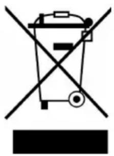
Symbol of a trash bin crossed with a diagonal line, no text or labels presentIf there is a legal regulation for the disposal of electrical and electronic devices in your country, this symbol on the product or on the packaging indicates that this product must not be disposed of with household waste. Instead, it must be taken to a collection point for the recycling of electrical and electronic equipment. By disposing of it in accordance with the rules, you are protecting the environment and the health of your fellow human beings from negative consequences. For information about the recycling and disposal of this product, please contact your local authority or your household waste disposal service.
MANUFACTURER & IMPORTER (UK)
Manufacturer:
Chal-Tec GmbH, Wallstrasse 16, 10179 Berlin, Germany.
Importer for Great Britain:
Berlin Brands Group UK Limited
PO Box 42
272 Kensington High Street
London, W8 6ND
United Kingdom
EU PRODUCT DATA SHEET
This document serves to demonstrate conformity with Regulation (EU) No 66/2014.
Specifications according to EN 30-2-1:2015
The energy efficiency of gas burners in a domestic hob is calculated as follows:
$$ E E _ {g a s b u r n e r} = \frac {E _ {\text { theoretic }}}{E _ {g a s b u r n e r}} \times 1 0 0 $$
| Symbol Burner Value Unit | ||||
| Model identification 10035464, 10046704, 10046706 | ||||
| Type of hob Gas Hob | ||||
| Number of gas burner - - 4 - | ||||
| Energy efficiency per gas burner | EE gas burner | Wok burner 52.2Rapid burner - Semi-rapid burner (2x)Auxiliary burner N/A | 58.1 | % |
| Energy efficiency per gas hob | EE gas hob | 56.1 % | ||
| Symbol Burner Value Unit | ||||
| Model identification 10035465, 10046705, 10046707 | ||||
| Type of hob Gas Hob | ||||
| Number of gas burner - - 5 - | ||||
| Energy efficiency per gas burner | EE gas burner | Wok burner 52.2Rapid burner 54.8Semi-rapid burner (2x)Auxiliary burner N/A | 58.1 | % |
| Energy efficiency per gas hob | EE gas hob | 55.8 % | ||
| Model identification 10039896 | ||||
| Type of hob Gas Hob | ||||
| Number of gas burner - - 2 - | ||||
| Energy efficiency per gas burner | EE gas burner | Wok burner - Rapid burner 55.8 Semi-rapid burner - Auxiliary burner N/A | % | |
| Energy efficiency per gas hob | EE gas hob | 55.8 % | ||
Chère cliente, cher client,
text_image
QR code image containing encoded data, no visible human-readable textSOMMAIRE
Fiche technique 58
text_image
Technical diagram of a four-cylinder electrical switch with numbered components for identification.text_image
Technical diagram of a gas stove or heating unit with numbered components labeled 2, 4, 5, and 6.text_image
Diagram showing a mechanical or structural component with dimension annotations and an arrow indicating rotation or movement.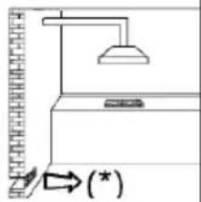
text_image
Diagram showing a lamp illuminating a wall-mounted device with an arrow indicating (*) direction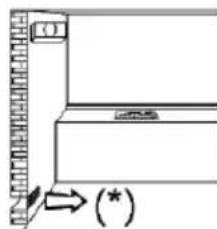
natural_image
Simple line drawing of a cabinet or shelf with an arrow pointing to the front panel (no text or symbols)Figure 1 Figure 2 Figure
other
| Dimension | Value | | --------- | ----- | | Top Section | 10039896 | | Bottom Section | 275 | | Inner Box | 114 | | Middle Box | 64 | | Total Height | 750 | Figure 4natural_image
Technical line drawing of a mechanical component with circular holes and mounting brackets (no text or symbols)Figure 6 Figure 7
text_image
K V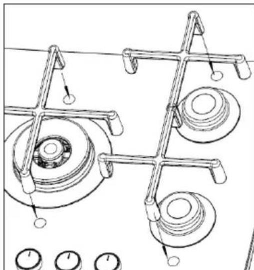
natural_image
Technical line drawing of mechanical components with no visible text or symbolsFigure 8
INSTALLATION DU BRANCHEMENT AU GAZ (INSTALLATEUR)
text_image
Tc Ac C T Figure 9Allumage manuel
natural_image
Line drawing of two identical cooking pots with heating elements, labeled Figure 11 (no text or symbols on the pots themselves)natural_image
Symbol of a trash bin crossed with a diagonal line, no text or labels presentBerlin Brands Group UK Limited
PO Box 42
272 Kensington High Street
London, W8 6ND
United Kingdom
FICHE DE DONNÉES PRODUIT UE
text_image
QR code image containing encoded data, no visible human-readable textÍNDICE
Datos técnicos 84
text_image
Technical diagram of a gas stove with numbered components for identificationtext_image
Technical diagram of a mechanical device with numbered components labeled 2, 4, 5, and 6.text_image
Diagram showing a mechanical or structural component with dimension annotations and an arrow indicating rotation or movement.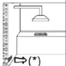
text_image
Diagram showing a lamp illuminating a wall-mounted device with an arrow indicating (*) and a vertical scale bar.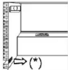
text_image
(*)other
| Dimension | Value | | --------- | ----- | | Top Section | 750 | | Middle Section | 114 Min | | Bottom Section | 565 | | Right Section | 64 Min | | Width (Width) | 485 | | Color (Color) | Black (Black) | | Color (Color) | White (White) | | Color (Color) | Dark Blue (Dark) | | Color (Color) | Light Blue (Light) | | Color (Color) | Grey (Grey) | | Color (Color) | Navy (Grey) | | Color (Color) | Navy (Grey) | | Color (Color) | Navy (Grey) | | Color (Color) | Navy (Grey) | | Color (Color) | Navy (Grey) | | Color (Color) | Navy (Grey) | | Color (Color) | Navy (Grey) | | Color (Color) | Navy (Grey) | | Color (Color) | Navy (Grey) | | Color (Color) | Navy(Grey) | | Color (Color) | Navy(Grey) | | Color (Color) | Navy(Grey) | | Color (Color) | Navy(Grey) | | Color (Color) | Navy(Grey) | | Color (Color) | Navy(Grey) | | Color (Color) | Navy(Grey) | | Color (Color) | Navy(Grey) | | Color (Color) | Navy(Grey) | | Color (Color) | Navy(Gray) | | Color (Color) | Navy(Gray) | | Color (Color) | Navy(Gray) | | Color (Color) | Navy(Gray) | | Color (Color) | Navy(Gray) | | Color (Color) | Navy(Gray) | | Color (Color) | Navy(Gray) | | Color (Color) | Navy(Gray) | | Color (Color) | Navy(Gray) | | Color (Color) | Navy(Gray)other
| Dimension | Value | | --------- | ----- | | Width | 750 | | Height | 114 | | Width-to-Height Ratio | 275 | | Minimum | 64 | | Maximum | 485 |natural_image
Technical line drawing of a mechanical component with circular holes and mounting brackets (no text or symbols)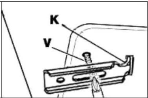
text_image
K Vnatural_image
Technical line drawing of mechanical components with no visible text or symbolsIlustración 8
natural_image
Symbol of a trash bin crossed with a diagonal line, no text or numbers presentBerlin Brands Group UK Limited
PO Box 42
272 Kensington High Street
London, W8 6ND
United Kingdom
FICHA TÉCNICA DEL PRODUCTO UE
text_image
QR code image containing encoded data, no visible human-readable textINDICE
Dati tecnici 112
text_image
Technical diagram of a gas stove with numbered components for identificationtext_image
Technical diagram of a gas stove or heating unit with numbered components labeled 2, 4, 5, and 6.text_image
Diagram showing a mechanical or structural component with dimension annotations and an arrow indicating rotation or movement.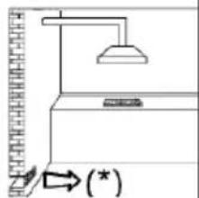
text_image
Diagram showing a lamp above a kitchen counter with an arrow indicating (*) and a wall-mounted device.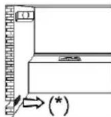
natural_image
Simple line drawing of a cabinet or shelf with an arrow pointing to the front panel (no text or symbols)Figura 1 Figura 2 Figura 3
other
| Dimension | Value | | --------- | ----- | | Top Section | 10035464 | | Bottom Section | 750 | | Bottom Section | 64 Min | | Bottom Section | 485 | | Bottom Section | 114 Min | | Bottom Section | 565 | Figure 4Numero articolo 10035465, 10046705, 10046707
text_image
750 114 Min 735 64 Min 475Figura 4
other
| Dimension | Value | | --------- | ----- | | Top Section | 750 | | Bottom Section | 114, 275, 485, 64 Min, 750 | | Figure 4: Numero articolo 10039896natural_image
Technical line drawing of a mechanical component with circular holes and mounting brackets (no text or symbols)Figura 6 Figura 7
text_image
K V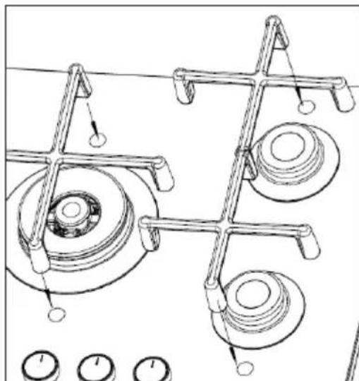
natural_image
Technical line drawing of mechanical components with no visible text or symbolsFigure 8
COLLEGARE L'ALLACCIAMENTO DEL GAS (INSTALLATORE)
The image contains no text or characters.
natural_image
Line drawing of two identical cooking pots with heating elements, labeled Figura 11 (no text or symbols on the pots themselves)| Diametro pentola/padella (ø in cm) | ||||
| Codice arti-colo | Wok Bruciatore rapido | Bruciatore semi-rapido | Bruciatore ausiliario | |
| 10035464, 10046704, 10046706 | 24-26 - 20 | |||
| 10035465, 10046705, 10046707 | 24-26 24-26 20-24 10-15 | |||
| 10039896 - 22-24 - 10-15 | ||||
natural_image
Symbol of a trash bin crossed with a diagonal line, no text or labels presentPRODUTTORE E IMPORTATORE (UK)
Produttore:
Chal-Tec GmbH, Wallstraße 16, 10179 Berlino, Germania.
Berlin Brands Group UK Limited
PO Box 42
272 Kensington High Street
London, W8 6ND
United Kingdom
