GOF 20-12 Professional - Milling machine BOSCH - Free user manual and instructions
Find the device manual for free GOF 20-12 Professional BOSCH in PDF.

| Product type | Professional router |
| Brand | Bosch |
| Model | GOF 20-12 Professional |
| Nominal absorbed power | 2000 W |
| Idle speed | 10 000 – 25 000 rpm |
| Speed preselection | Yes (6-position wheel) |
| Constant electronic | Yes |
| Compatible collet chuck | 8–12 mm (1/4–1/2 inch) |
| Cradle travel | 80 mm |
| Weight (without cable) | 6.3 kg |
| Protection class | II (double insulation) |
| Power supply | Mains 230 V (depending on version) |
| Dust extraction connection | Yes (hose Ø 35 mm) |
| Dimensions (L x W x H) approx. | 250 x 200 x 280 mm |
| Main functions | Grooving, edge profiling, shape cutting, slotting, template, plunge |
| Maintenance and cleaning | Clean ventilation slots, use dust extraction, have cable replacement done by Bosch service center |
| Safety | Spindle lock button, lockable switch, double insulation, chip deflector |
| Spare parts and repairability | HSS/HM router bits, template guides, parallel guide, roller guide, dust hood, adapters; repair by Bosch authorized service center |
| General information | Suitable for wood, plastics, light materials, and non-ferrous metals (with reduced speed) |
Frequently Asked Questions - GOF 20-12 Professional BOSCH
User questions about GOF 20-12 Professional BOSCH
0 question about this device. Answer the ones you know or ask your own.
Ask a new question about this device
Download the instructions for your Milling machine in PDF format for free! Find your manual GOF 20-12 Professional - BOSCH and take your electronic device back in hand. On this page are published all the documents necessary for the use of your device. GOF 20-12 Professional by BOSCH.
USER MANUAL GOF 20-12 Professional BOSCH
natural_image
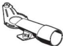
3D rendered mechanical device with multiple ports and mounting base (no visible text or symbols)en Original instructions
fr Notice originale
pt Manual original
zh 正本使用说明书
zh原始使用說明書
English ...... Page 7
Français Page 13

natural_image
Mechanical assembly diagram showing a pressor clamping operation on a workbench (no text or symbols visible)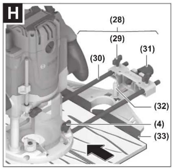
6
English
Safety Instructions
General Power Tool Safety Warnings
WARNING
Read all safety warnings, instructions, illustrations and specifica-
tions provided with this power tool. Failure to follow all instructions listed below may result in electric shock, fire and/or serious injury.
Save all warnings and instructions for future reference.
The term "power tool" in the warnings refers to your mains-operated (corded) power tool or battery-operated (cordless) power tool.
Work area safety
▶ Keep work area clean and well lit. Cluttered or dark areas invite accidents.
▶ Do not operate power tools in explosive atmospheres, such as in the presence of flammable liquids, gases or dust. Power tools create sparks which may ignite the dust or fumes.
▶ Keep children and bystanders away while operating a power tool. Distractions can cause you to lose control.
Electrical safety
▶ Power tool plugs must match the outlet. Never modify the plug in any way. Do not use any adapter plugs with earthed (grounded) power tools. Unmodified plugs and matching outlets will reduce risk of electric shock.
▶ Avoid body contact with earthed or grounded surfaces, such as pipes, radiators, ranges and refrigerators. There is an increased risk of electric shock if your body is earthed or grounded.
▶ Do not expose power tools to rain or wet conditions. Water entering a power tool will increase the risk of electric shock.
▶ Do not abuse the cord. Never use the cord for carrying, pulling or unplugging the power tool. Keep cord away from heat, oil, sharp edges or moving parts.
Damaged or entangled cords increase the risk of electric shock.
▶ When operating a power tool outdoors, use an extension cord suitable for outdoor use. Use of a cord suitable for outdoor use reduces the risk of electric shock.
▶ If operating a power tool in a damp location is unavoidable, use a residual current device (RCD) protected supply. Use of an RCD reduces the risk of electric shock.
Personal safety
▶ Stay alert, watch what you are doing and use common sense when operating a power tool. Do not use a power tool while you are tired or under the influence of drugs, alcohol or medication. A moment of inatten-
tion while operating power tools may result in serious personal injury.
▶ Use personal protective equipment. Always wear eye protection. Protective equipment such as a dust mask, non-skid safety shoes, hard hat or hearing protection used for appropriate conditions will reduce personal injuries.
▶ Prevent unintentional starting. Ensure the switch is in the off-position before connecting to power source and/or battery pack, picking up or carrying the tool. Carrying power tools with your finger on the switch or energising power tools that have the switch on invites accidents.
Remove any adjusting key or wrench before turning the power tool on. A wrench or a key left attached to a rotating part of the power tool may result in personal injury.
▶ Do not overreach. Keep proper footing and balance at all times. This enables better control of the power tool in unexpected situations.
▶ Dress properly. Do not wear loose clothing or jewellery. Keep your hair and clothing away from moving parts. Loose clothes, jewellery or long hair can be caught in moving parts.
▶ If devices are provided for the connection of dust extraction and collection facilities, ensure these are connected and properly used. Use of dust collection can reduce dust-related hazards.
Do not let familiarity gained from frequent use of tools allow you to become complacent and ignore tool safety principles. A careless action can cause severe injury within a fraction of a second.
Power tool use and care
▶ Do not force the power tool. Use the correct power tool for your application. The correct power tool will do the job better and safer at the rate for which it was designed.
▶ Do not use the power tool if the switch does not turn it on and off. Any power tool that cannot be controlled with the switch is dangerous and must be repaired.
▶ Disconnect the plug from the power source and/or remove the battery pack, if detachable, from the power tool before making any adjustments, changing accessories, or storing power tools. Such preventive safety measures reduce the risk of starting the power tool accidentally.
▶ Store idle power tools out of the reach of children and do not allow persons unfamiliar with the power tool or these instructions to operate the power tool. Power tools are dangerous in the hands of untrained users.
- Maintain power tools and accessories. Check for misalignment or binding of moving parts, breakage of parts and any other condition that may affect the power tool's operation. If damaged, have the power tool repaired before use. Many accidents are caused by poorly maintained power tools.
8 | English
▶ Keep cutting tools sharp and clean. Properly maintained cutting tools with sharp cutting edges are less likely to bind and are easier to control.
▶ Use the power tool, accessories and tool bits etc. in accordance with these instructions, taking into account the working conditions and the work to be performed. Use of the power tool for operations different from those intended could result in a hazardous situation.
▶ Keep handles and grasping surfaces dry, clean and free from oil and grease. Slippery handles and grasping surfaces do not allow for safe handling and control of the tool in unexpected situations.
Service
▶ Have your power tool serviced by a qualified repair person using only identical replacement parts. This will ensure that the safety of the power tool is maintained.
Safety information for plunge routers and edge routers
▶ Hold the power tool by insulated gripping surfaces only, because the cutter may contact its own cord. Cutting a "live" wire may make exposed metal parts of the power tool "live" and could give the operator an electric shock.
▶ Use clamps or another practical way to secure and support the workpiece to a stable platform. Holding the work by your hand or against the body leaves it unstable and may lead to loss of control.
The permitted speed of the cutting bit must be at least equal to the maximum speed marked on the power tool. If cutting bits run faster than their rated speed, they may break and fly off.
▶ Routers and other accessories must be able to fit exactly in the tool holder (collet) of your power tool. Application tools that do not fit exactly in the tool holder of the power tool will turn unevenly, vibrate heavily and may cause a loss of control.
▶ Only bring the power tool into contact with the workpiece when switched on. Otherwise there is danger of kickback if the cutting tool jams in the workpiece.
▶ Do not put your hands in the routing area or close to the router. Grip the auxiliary handle with your other hand. Holding the router with both hands avoids injury.
▶ Never rout over metal objects, nails or screws. The router could become damaged and cause increased vibration.
▶ Use suitable detectors to determine if utility lines are hidden in the work area or call the local utility company for assistance. Contact with electric lines can lead to fire and electric shock. Damaging a gas line can lead to explosion. Penetrating a water line causes property damage or may cause an electric shock.
▶ Do not use blunt or damaged routers. Blunt or damaged routers cause increased friction, create imbalances and may become jammed.
▶ Always wait until the power tool has come to a complete stop before placing it down. The application tool can jam and cause you to lose control of the power tool.
▶ Hold the power tool firmly with both hands and make sure you have a stable footing. The power tool can be more securely guided with both hands.
Product Description and Specifications

Read all the safety and general instructions. Failure to observe the safety and general instructions may result in electric shock, fire and/or serious injury.
Please observe the illustrations at the beginning of this operating manual.
Intended use
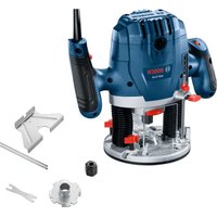
The power tool is intended for copy routing as well as routing grooves, edges, profiles and elongated holes in wood, plastic and light building materials while resting firmly on the workpiece.
Can even be used to machine non-ferrous metals when used at a low speed with the appropriate router bits.
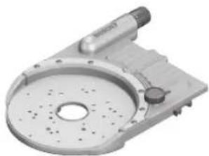
Product features
The numbering of the product features refers to the diagram of the power tool on the graphics page.
(1) Right handle (insulated gripping surface)
(2) Spindle lock button
(3) Chip protection
(4) Wing bolt for parallel guide rods (2x)
(5) Base plate
(6) Guide plate
(7) Holder for parallel guide rods
(8) Step buffer
(9) Wing bolt for depth stop adjustment
(10) Slide with index mark
(11) Left handle (insulated gripping surface)
(12) Clamping lever for locking the routing depth
(13) Scale for setting the routing depth
(14) Depth stop
(15) Scale for fine adjustment of the routing depth
(16) Adjustment knob for fine adjustment of depth-of-cut (plunge base)
(17) Speed preselection thumbwheel
(18) Router bit ^4
(19) On/off switch
(20) Lock-on button and unlock key for on/off switch
(21) Open-ended spanner (17 mm, 24 mm)
(22) Cap nut with collet
(23) Dust extraction adapter (plunge base)
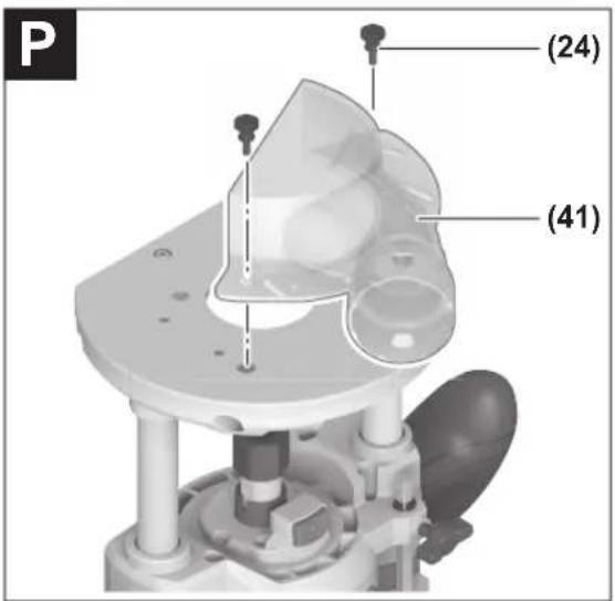
(24) Knurled screw for dust extraction adapter (2x)
(25) Extraction hose (dia. 35 mm) ^a)
(26) Dust extraction adapter (non-plunge base) ^a)
(27) Intermediate ring for extraction adapter ^a)
(28) Parallel guide
(29) Wing bolt for parallel guide coarse adjustment
(30) Guide rod for parallel guide
(31) Knob for parallel guide fine adjustment
(32) Centring pin
(33) Adjustable fence for parallel guide
(34) SDS guide-bushing adapter
(35) Fastening screw for guide-bushing adapter (2x)
(36) Release lever for guide-bushing adapter
(37) Guide bushing
(38) Plunge base
(39) Fastening screw for guide plate
(40) Centring pin ^a)
(41) Extraction hood for edge routing
(42) Guide wheel ^1
a) This accessory is not part of the standard scope of delivery.
Technical data
| Plunge router GOF 20-12 | |
| Article number | 3 601 F27 2.. |
| Rated power input W 2000 | |
| No-load speed min | 10000-25000 |
| Speed preselection ● | |
| Constant electronic control ● | |
| Connection for dust extraction | |
| Compatible collets mm | 8-12 inches 14-12 |
| Router cage stroke mm 80 | |
| Weight ^A) kg 6.3 | |
| Protection class | 回/II |
A) Without mains connection cable
The specifications apply to a rated voltage [U] of 230 V. These specifications may vary at different voltages and in country-specific models.
Values can vary depending on the product, scope of application and environmental conditions. To find out more, visit www.bosch-professional.com/wac.
Fitting
▶ Pull the plug out of the socket before carrying out any work on the power tool.
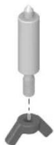
Inserting the router bit (see figure A)
▶ Wearing protective gloves while fitting and changing router bits is recommended.
Router bits are available in a wide variety of designs and qualities depending on the intended application.
Router bits made of high-performance high-speed steel (HSS) are suited to machining soft materials such as soft-wood and plastic.
Router bits with carbide tips are especially suitable for hard and abrasive materials such as hardwood and aluminium.
Original router bits from the extensive range of Bosch accessories are available from your specialist dealer. Only use undamaged and clean router bits.
Use router bits with a shank diameter of 12 mm wherever possible.
The router bit can be changed when the routing motor is mounted in the plunge base/non-plunge base. However, it is recommended to change the tool with the routing motor dismounted.
- Remove the routing motor from the plunge base/non-plunge base.
- Press and hold the spindle lock button (2) (①). If required, turn the spindle by hand until the locking mechanism engages.
Actuate the spindle lock button (2) only when at a standstill.
- Alternatively, you can lock the spindle with an additional open-ended spanner.
- Loosen the cap nut (22) with the open-ended spanner (21) (width across flats 17 mm and 24 mm) by turning it anticlockwise (②).
- Slide the router bit into the collet. The shank of the router bit must be immersed at least 20 mm into the collet.
- Tighten the cap nut (22) with the open-ended spanner (21) (width across flats 17 mm and 24 mm) by turning it clockwise. Release the spindle lock button (2) or remove the additional open-ended spanner.
▶ Do not insert a router bit with a diameter larger than 50 mm when the guide bushing is not mounted. These router bits will not fit through the base plate.
▶ Do not, under any circumstances, tighten the collet with the tightening nut until a router bit has been fitted. The collet may otherwise become damaged.
Dust/Chip Extraction
The dust from materials such as lead paint, some types of wood, minerals and metal can be harmful to human health. Touching or breathing in this dust can trigger allergic reactions and/or cause respiratory illnesses in the user or in people in the near vicinity.
Certain dusts, such as oak or beech dust, are classified as carcinogenic, especially in conjunction with wood treatment additives (chromate, wood preservative). Materials containing asbestos may only be machined by specialists.
10 | English
- Use a dust extraction system that is suitable for the material wherever possible.
- Provide good ventilation at the workplace.
- It is advisable to wear a P2 filter class breathing mask.
The regulations on the material being machined that apply in the country of use must be observed. - Avoid dust accumulation at the workplace. Dust can easily ignite.
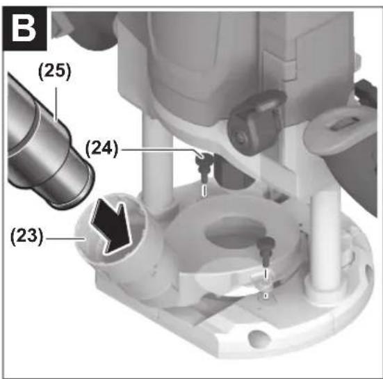
Fitting the dust extraction adapter on the plunge base (see figure B)
The dust extraction adapter (23) can be fitted to the front or the back using the hose connection.
When the guide-bushing adapter (34) is inserted, the guide-bushing adapter may need to be rotated 180° so that the extraction adapter (23) does not touch the release lever (36).
Fasten the dust extraction adapter (23) to the base plate (5) using the two knurled screws (24).
To ensure optimum extraction, the dust extraction adapter (23) must be cleaned regularly.
Fitting the dust extraction adapter (accessory) on the non-plunge base (see figure C)
The dust extraction adapter (26) can be fitted to the front or the back using the hose connection.
When the guide-bushing adapter (34) is inserted, fasten the extraction adapter (26) to the base plate (5) using the two knurled screws (24). For applications without the guide-bushing adapter (34), firstly mount the intermediate ring (27) to the extraction adapter (26) as shown in the figure.
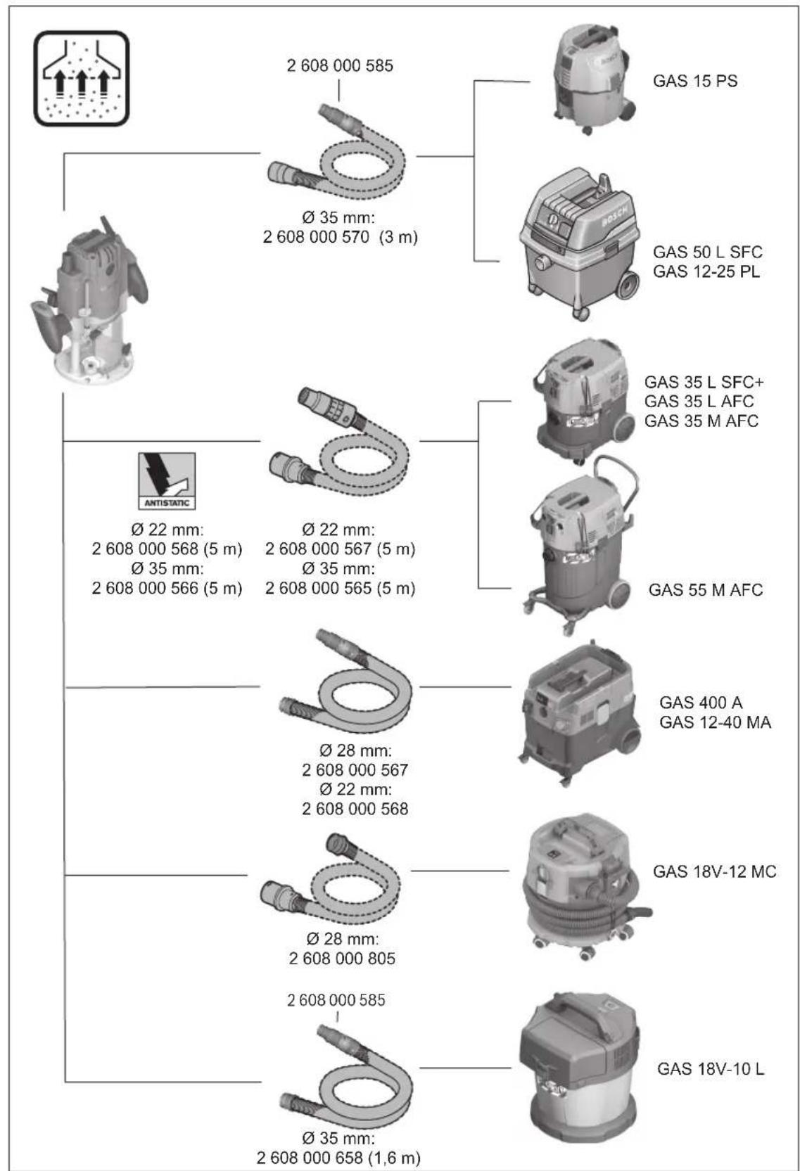
Connecting the dust extraction system
Attach an extraction hose (dia. 35 mm) (25) (accessory) to the fitted dust extraction adapter. Connect the dust extraction hose (25) to a dust extractor (accessory).
The power tool can be directly connected to the plug socket of a Bosch all-purpose dust extractor with remote starter. This dust extractor is started up automatically when the power tool is switched on.
The dust extractor must be suitable for the material being worked.
When extracting dry dust or dust that is especially detrimental to health or carcinogenic, use a special dust extractor.
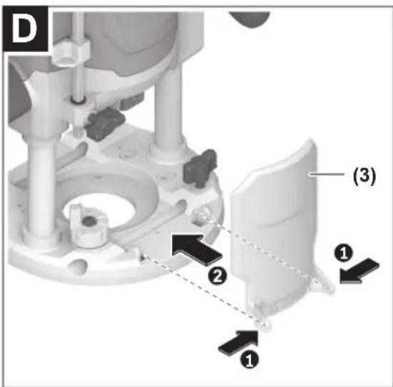
Fitting the chip protection (see figure D)
Push the chip protection (3) into the guide from the front so that it clicks into place. To remove it, hold the sides of the chip protection and pull it forwards.
Operation
▶ Products that are only sold in AUS and NZ: Use a residual current device (RCD) with a nominal residual current of 30 mA or less.
▶ Pay attention to the mains voltage. The voltage of the power source must match the voltage specified on the rating plate of the power tool.
Starting Operation
Preselecting the speed
You can preselect the required speed using the speed preselection thumbwheel (17), even during operation.
1-2 low speed
3-4 medium speed
5-6 high speed
The values shown in the table are guide values. The required speed is dependent on the material and the work conditions and can be determined by practical trials.
| Material Router bit diameter [mm] | Thumbwheel position | |
| Hardwood (beech) 4-10 | 5-6 | |
| 12-20 | 3-4 | |
| 22-40 | 1-2 | |
| Softwood (pine) 4-10 | 5-6 | |
| 12-20 | 3-6 | |
| 22-40 | 1-3 | |
| Chipboard 4-10 | 3-6 | |
| 12-20 | 2-4 | |
| 22-40 | 1-3 | |
| Plastics 4-15 | 2-3 | |
| 16-40 | 1-2 | |
| Aluminium 4-15 | 1-2 | |
| 16-40 | 1 | |
After working at a low speed for an extended period, you should operate the power tool at the maximum speed for approximately three minutes without load to cool it down.
Switching on/off
Before switching on, set the required routing depth.
To switch on the power tool, gently press the lock-on button and unlock key for the on/off switch (20), then press the on/off switch (19) and keep it pressed.
To lock the power tool, switch the power tool on and press the lock-on button and unlock key for the on/off switch (20). First release the on/off switch (19) and then the lock-on button and unlock key for the on/off switch (20).
To switch off the power tool, release the on/off switch (19); or, if the switch is locked with the lock-on button (20), briefly press the on/off switch (19) and then release it.
Constant electronic control
The Constant Electronic keeps the speed at no load and under load virtually consistent, guaranteeing uniform performance.
Soft start
The electronic soft start limits the torque when the power tool is switched on and increases the service life of the motor.
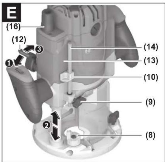
Setting the routing depth (see figure E)
The routing depth must only be set while the power tool is switched off.
To set the rough routing depth, proceed as follows:
- Place the power tool with a fitted router bit onto the workpiece you want to machine.
- Set the step buffer (8) to the lowest step; the step buffer audibly clicks into place.
- Loosen the wing bolt on the depth stop (9) so that the depth stop (14) can move freely.
- Push the clamping lever for locking the routing depth (12) in direction ① and slowly move the router down until the router bit (18) is touching the surface of the workpiece. Release the clamping lever for locking the routing depth (12) again to lock this depth. If necessary, push the clamping lever for locking the routing depth (12) in direction ② to fully lock it.
- Press the depth stop (14) down until it is resting on the step buffer (8). Set the slide with the index mark (10) to position 0 on the routing depth scale (13).
- Set the depth stop (14) to the required routing depth and tighten the wing bolt on the depth stop (9). Take care not to accidentally move the index mark (10).
- Push the clamping lever for locking the routing depth (12) in direction ① and move the router to the highest position.
For larger routing depths, you should perform the cut in several phases, so that only a small amount of material is removed after each cut. You can use the step buffer (8) to divide the routing process into multiple steps. To do this, set the required routing depth with the smallest step of the step buffer and, for the first cutting phases, select the higher steps to start with.
After making a test cut, you can set the routing depth to the exact level you require by turning the knob (16). Turning it clockwise increases the routing depth; turning it anticlockwise decreases the routing depth. The scale (15) can be used for guidance. One revolution corresponds to an adjustment range of 1.5 mm. Each of the graduation marks on the upper edge of the scale (15) changes the adjustment range by 0.1 mm. The maximum adjustment range is ±16 mm.
Working Advice
▶ Protect router bits against shock and impact.
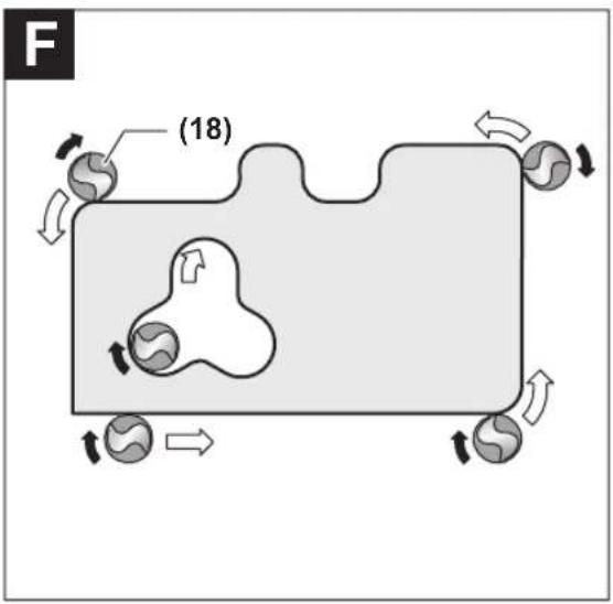
Routing direction and routing process (see figure F)
Routing must always be carried out with the workpiece being moved against the direction in which the router bit (18) is turning (up cut). If the workpiece is moved in the same direction as the router bit is turning (down cut), the power tool may be pulled out of your hands.
Routing with the plunge base
Set the required routing depth.
Place the power tool with a fitted router bit onto the workpiece you want to machine and switch on the power tool.
Press the release lever for plunge action down and slowly guide the router down until the set routing depth is reached. Let go of the release lever again in order to lock the plunging depth.
Carry out the routing process with a uniform feed.
When routing is complete, move the router back to the highest position.
Switch off the power tool after routing.
Routing with the non-plunge base
Set the required routing depth.
Switch on the power tool and guide it to the point you want to machine.
Carry out the routing process with a uniform feed.
Switch the power tool off.
▶ Do not put the power tool down before the router bit has come to a complete stop. Application tools that are still running can cause injuries.
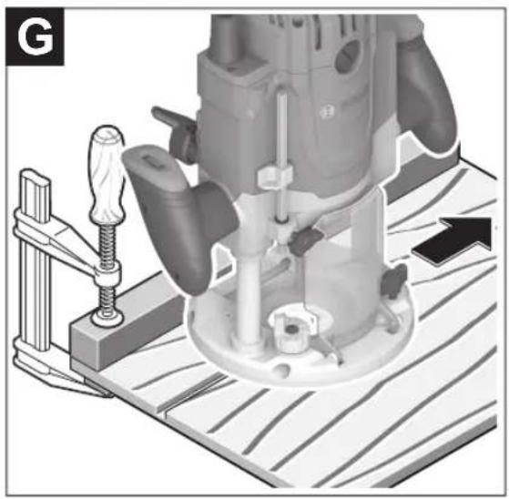
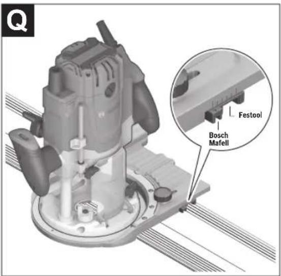
Routing with an auxiliary guide (see figure G)
For working large workpieces, e. g., when routing grooves, a board or straight edge can be securely fastened to the workpiece as an auxiliary guide. The multifunction router can be guided alongside the path of this auxiliary guide. When using the plunge base (38), guide the guide plate (flattened side) of the multifunction router alongside the auxiliary guide.
For edge and profile routing without a parallel guide, the router bit must be fitted with a pilot pin or a ball bearing. While it is switched on, guide the power tool towards the workpiece from the side until the pilot pin or the ball bearing of the router bit is touching the side of the workpiece edge that you want to machine.
Guide the power tool along the workpiece edge. Pay attention that the router is positioned perpendicularly. Too much pressure can damage the edge of the workpiece.
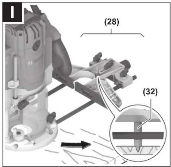
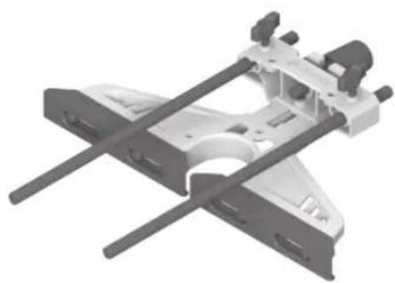
Routing with a Parallel Guide (see figures H and I)
Slide the parallel guide (28) with the guide rods (30) into the base plate (5) and tighten it with the wing bolts (4) according to the required dimension.
Additionally, the parallel guide can be adjusted lengthwise with the wing bolts (29).
Fine adjustment of the length is possible with the adjustment knob (31) after loosening both wing bolts (29). One revolution corresponds to an adjustment range of 2.0 mm. Each of the graduation marks on the knob (31) changes the adjustment range by 0.1 mm. Make sure the tip of the centring pin (32) reaches the surface of the workpiece.
The effective contact surface of the parallel guide can be adjusted using the fence (33).
While it is switched on, guide the power tool along the workpiece edge with a uniform feed and while applying lateral pressure to the parallel guide.
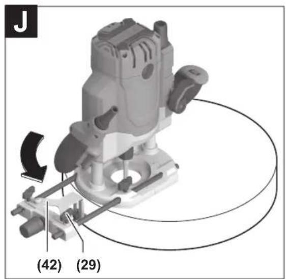
Routing with a Guide Wheel (see figure J)
Mount the guide wheel (42), as shown in the figure.
Position the guide wheel on the curved edge of a plate.
12 | English
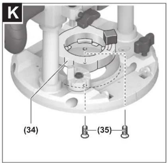
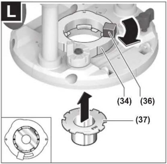
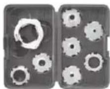
Routing with the guide bushing (see figures K-L)
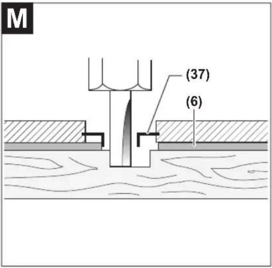
Using the guide bushing (37), you can transfer contours from templates or patterns to the workpiece.
Select the guide bushing that is suitable for the thickness of the template or pattern. Due to the protruding height of the guide bushing, the template must have a minimum thickness of 8 mm.
In order to use the guide bushing (37), the SDS guide-bushing adapter (34) must first be inserted into the guide plate (6).
Place the guide-bushing adapter (34) from above onto the guide plate (6) and tighten it firmly with the 2 fastening screws (35). Ensure that the release lever for the guide-bushing adapter (36) is freely movable.
Push the release lever (36) in the direction of the arrow and insert the guide bushing (37) from below into the SDS guide-bushing adapter (34). The coding cams must audibly click into the recesses of the guide bushing (37).
Check the clearance from the router bit centre and guide-bushing edge (see "Centring the base plate (see figure N)", page 12).
▶ Select a router bit with a diameter that is smaller than the interior diameter of the guide bushing.
Routing process
Note: Be aware that the router bit (18) always protrudes slightly from the base plate (5). Do not damage the template or the workpiece.
Switch the power tool on and move it with the guide bushing (37) towards the template.
When using the plunge base (38): Press the release lever for plunge action down and slowly guide the router down until the set routing depth is reached. Let go of the release lever again in order to lock the plunging depth.
Guide the power tool with the protruding guide bushing (37) along the template using lateral pressure.
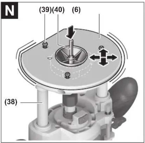
Centring the base plate (see figure N)
To ensure that the distance from the router bit centre to the guide-bushing edge is uniform, the guide bushing (37) and the guide plate (6) can be adjusted to each other, if required.
When using the plunge base (38): Press the release lever for plunge action down and slowly guide the router down until the set routing depth is reached. Let go of the release lever again in order to lock the plunging depth.
Loosen the fastening screws (39) approx. two turns so that the guide plate (6) is freely movable.
Insert the centring pin (40) into the tool holder as shown in the figure. Hand-tighten the cap nut so that the centring pin can still be moved freely.
Align the centring pin (40) and the guide bushing (37) to each other by slightly moving the guide plate (6).
Retighten the fastening screws (39).
Remove the centring pin (40) from the tool holder.
When using the plunge base (38): Press the release lever for plunge action and guide the router back to the uppermost position.
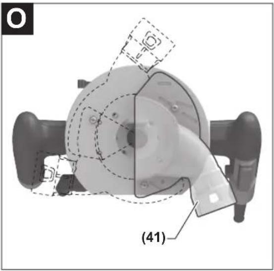
Routing with an extraction hood (see figures O-P)
For routing edges, the extraction hood (41) can additionally be used.
Fasten the extraction hood (41) to the base plate (5) with the two screws. The extraction hood (41) can be fastened in three different positions, as shown in the figure.
Remove the extraction hood again for routing smooth plane surfaces.
Use the FSN OFA adapter (1 600 Z00 00G).
Maintenance and Service
Maintenance and Cleaning
▶ Pull the plug out of the socket before carrying out any work on the power tool.
▶ To ensure safe and efficient operation, always keep the power tool and the ventilation slots clean.
In extreme conditions, always use a dust extractor if possible. Clean ventilation slots frequently using a brush and install a residual current device (RCD) upstream. When machining metals, conductive dust can settle inside the power tool, which can affect its protective insulation.
In order to avoid safety hazards, if the power supply cord needs to be replaced, this must be done by Bosch or by an after-sales service centre that is authorised to repair Bosch power tools.
After-Sales Service and Application Service
Malaysia
Tel.: (03) 79663194

You can find our service addresses and links to the repair service and spare parts ordering at www.bosch-pt.com/serviceaddresses
In all correspondence and spare parts orders, please always include the 10-digit article number given on the nameplate of the product.
Disposal
The power tool, accessories and packaging should be recycled in an environmentally friendly manner.
Do not dispose of power tools along with household waste.
Français
(6) Plaque coulissante
www.bosch-pt.com/serviceaddresses
www.bosch-pt.com/serviceaddresses
natural_image
3D rendered mechanical part with no visible text or symbols
natural_image
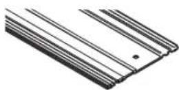
Three parallel cylindrical rods with a label '2 609 2' on the right side (no other text or symbols)2 609 200 145 (L = 0,8 m)
natural_image
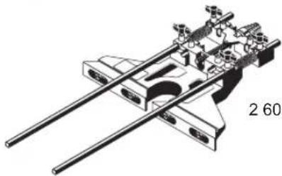
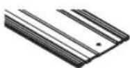
Technical line drawing of a mechanical assembly with two rods and a central component (no text or symbols)2 607 001 387
1 600 Z00 03X
1 600 A00 11C
1 600 A00 1FB
2 617 017 128
1 600 Z00 005 (800 mm)
1 600 Z00 006 (1100 mm)
1 600 Z00 00F (1600 mm)
1 600 Z00 007 (2100 mm)
1 600 Z00 008 (3100 mm)

natural_image
3D rendered illustration of a conical plastic object with two flanged ends (no text or symbols)1 619 PS3 865
1 600 Z00 03V (800 mm)
1 600 Z00 03W (1600 mm)
natural_image
3D rendered mechanical component with circular base and mounting bracket (no visible text or symbols)1 600 Z00 00G

natural_image
Two gray rectangular panels with white gear-like cutouts and a central hole, no text or symbols visible.(Metric)
2 608 190 063
natural_image
Two grayscale gear illustrations with holes, no text or symbols visible(Inch)
2 608 190 064
natural_image
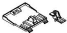
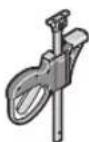
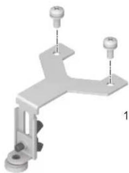
3D rendering of a mechanical clamp or bracket assembly with metal plates and mounting holes (no text or symbols visible)1 619 PS3 851
1 619 PS3 850
natural_image
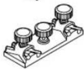
3D mechanical bracket component with two cylindrical pins and a base mount (no text or symbols visible)1 619 PS3 849
natural_image
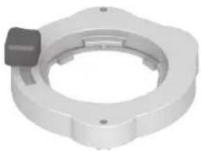
3D rendering of a white mechanical ring component with a black clip and mounting holes (no text or symbols)2 610 041 329