TALIA 601 - Basket Apelson - Free user manual and instructions
Find the device manual for free TALIA 601 Apelson in PDF.


User questions about TALIA 601 Apelson
0 question about this device. Answer the ones you know or ask your own.
Ask a new question about this device
Download the instructions for your Basket in PDF format for free! Find your manual TALIA 601 - Apelson and take your electronic device back in hand. On this page are published all the documents necessary for the use of your device. TALIA 601 by Apelson.
USER MANUAL TALIA 601 Apelson
natural_image
Simple line drawing of a kitchen chimney (no text or symbols)INSTRUCTIONS FOR USEEN
MANUAL DE INSTRUCCIONESES
FR MANUEL D'UTILISATION
PT MANUAL DE INSTRUÇÕES
natural_image
Technical line drawings of a ceiling structure with ventilation grilles and mounting brackets (no text or symbols)Content
1....Safety instructions
2....Installation
3....Start using your cooker hood
4....Troubleshooting
5....Maintenance and cleaning
6 Environment protection
SAFETY INSTRUCTIONS
This manual explains the proper installation and use of your cooker hood, please read it carefully before using even if you are familiar with the product. The manual should be kept in a safe place for future reference.
Never to do:
- Donottrytousethe cookerhoodwithout thegreasefiltersorif thefiltersare excessivelygreasy!
- Donotinstallabovea cookerwithahighlevel grill.
● Donotleavefrying pansunattended duringusebecause overheatedfatsoroils mightcatchfire.
● Neverleavenaked flamesunderthe cookerhood.

- Ifthecookerhoodis damaged, donot attempttouse.
●Donotflambéunder thecookerhood.
●CAUTION:Accessible partsmaybeomehot whenusedwith cookingappliances.
● Theminimumdistance betweenthesupporting surfaceforthecooking vesselsonthehoband the lowestpartofthe cookerhood.(When thecookerhoodis locatedaboveagas appliance, thisdistance shallbeatleast65cm)
●Theairmustnotbe dischargedintoaflue thatisusedfor exhaustingfumesfrom
appliancesburninggas orotherfuels.Cooker hoodsandother cookingfume extractorsmay adverselyaffectthe safeoperationof appliancesburninggas orotherfuels(including thoseinotherrooms) duetobackflowof combustiongases. Thesegasescan potentiallyresultin carbonmonoxide poisoning.After installationofacooker hoodorothercooking fumeextractor,the operationofopenflued gasappliancesshould betestedbya competentpersonto ensurethatbackflow ofcombustiongases doesnotoccur.
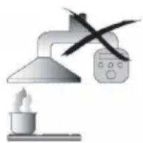
natural_image
Illustration of a desk lamp illuminating a steaming cup with a crossed-out X-shaped device (no text or symbols)Always to do:
● Important! Always switchofftheelectricity supplyatthemains duringinstallationand maintenancesuchas lightbulbreplacement.
●Thecookerhoodmust beinstalledin accordancewiththe installationinstructions andallmeasurements followed.
● Allinstallationwork mustbecarriedout by acompetentperson or qualifiedelectrician.
●Pleasedisposeofthe packingmaterial carefully. Childrenare vulnerable to it.
● Payattentiontothe sharpedgesinsidethe cookerhoodespecially duringinstallationand cleaning.
●Makesuretheducting hasnobendssharper than90degreesasthis willreducethe efficiencyofthecooker hood.
●Warning: Failureto install the screws for fixing device in accordance with these instructions may result in electrical hazards.
● Warning: Before obtaining access to terminals, all supply circuits must be disconnected.
- Ifthevoltageratingof the lamp is less than theratedvoltageofthe appliance, the voltage ratingofthelampshall alsobemarkedonor nearthelampholder.
Always to do:
●Alwaysputlidsonpots andpanswhen cookingonagas cooker.
- Wheninextraction mode,airintheroom isbeingremovedby thecookerhood. Pleasemakesurethat properventilation measuresarebeing observed.Thecooker
hoodremovesodours fromroombutnot steam.
● Thereshallbe adequateventilation of theroomwhenthe cookerhoodisusedat thesametimeas appliancesburninggas orotherfuels.
●Cookerhoodisfor domesticuseonly.
- If the supply cord is damaged, it must be replaced by the manufacturer, its service agent or similarly qualified persons in order to avoid a hazard.
●Thisapplianceisnot intendedforuseby persons(including children)withreduced physical,sensoryor mentalcapabilities,or lackofexperienceand
knowledge, unless they have been given supervision or instruction concerning use of the appliance by aperson responsible for their safety
● Childrenshouldbe supervisedtoensure thattheydonotplay withtheappliance.
● This appliance can be used by children aged from 8 years and above and persons with reduced physical, sensory or mental capabilities or lack of experience and knowledge if they have been given supervision or instruction concerning use of the appliance in asafeway and understand the hazards involved. Children shall not play with the appliance. Cleaning and user maintenances shall not be made by children without supervision.
text_image
Prohibition sign with two figures holding a diagonal line, symbolizing no smoking or prohibitionAlways to do:
● Caution: The appliance and its accessible part scan become hot during operation. Becareful to avoid touching the heating elements. Children younger than 8 years old should stay away unless they are under permanent supervision.
●Thereisafireriskif cleaningisnotcarried outinaccordancewith theinstructions.
●Regulationsconcerning thedischargeofair havetobefulfilled.
● Cleanyourappliance periodically by following themethod given in the chapter MAINTENANCE.
● Forsafetyreason, pleaseuseonlythe samesizeoffixingor mountingscrewwhich arerecommendedin thisinstructionmanual.
● Regardingthedetails aboutthemethodand frequencyofcleaning, pleasereferto maintenanceand cleaningsectioninthe instructionmanual.
● Regarding the information about how the appliance is to be fixed to its support, pleasereferto Operation section, the Installation procedures in this manual.
● Cleaninganduser maintenanceshallnot
bemadebychildren withoutsupervision.
- Whenthecookerhood andappliances suppliedwithenergy otherthanelectricity aresimultaneouslyin operation,thenegative pressureintheroom mustnotexceed4Pa (4x10 ^-5 bar).
●WARNING:Dangerof fire:donotstoreitems onthecooking surfaces.
●A steamcleanerisnot tobeused.
●NEVERtryto extinguishafirewith water, butswitchoff theapplianceandthen coverflamee.g.witha lidorafireblanket.
INSTALLATION (VENT OUTSIDE)
MOUNTING OF THE V-FLAP
If the cooker hood does not have an assembled V-flap1, you should mount the half-part stoits body. The images only show an example of how to mount the V-flap, because the outlet may vary according to different models and configurations.
TomounttheV-flap1youshould:
- Mounttwohalf-parts2intothebody6
•thepin3shouldbetoporiented;
•theaxis4shouldbeinsertedintheholes5onthebody;
•repeatalltheoperationsforthe2ndhalf-part
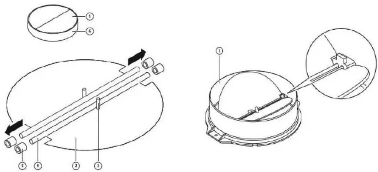
INSTALLATION
If you have an outlet to the outside, your cooker hood can be connected as below picture by means of an extraction duct (enamel, aluminum, flexible pipe or non-flammable material with an interior diameter of 150 mm)
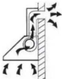
natural_image
Diagram of airflow around a mechanical component with directional arrows indicating motion (no text or symbols)-
Beforeinstallation, turntheunitoff.
-
The cookerhood should be placed at distance of 65\~75 cm above the cooking surface for best effect.

text_image
65cm 75cmPic1
- Afterdecidetheinstallationheightofthehood, drill6pcsholesof∅8mminthe appropriatepositionsonthewallandscrewthewallplugsintotheholes.Install 2pcs screws (4*30mm) for hanging the appliance. And use 2pcs screws (4*40mm) to fix inside chimney bracket on the wall. The fixed position of the insidechimneybracketisthehighestpositionofchimney.Seepic2.
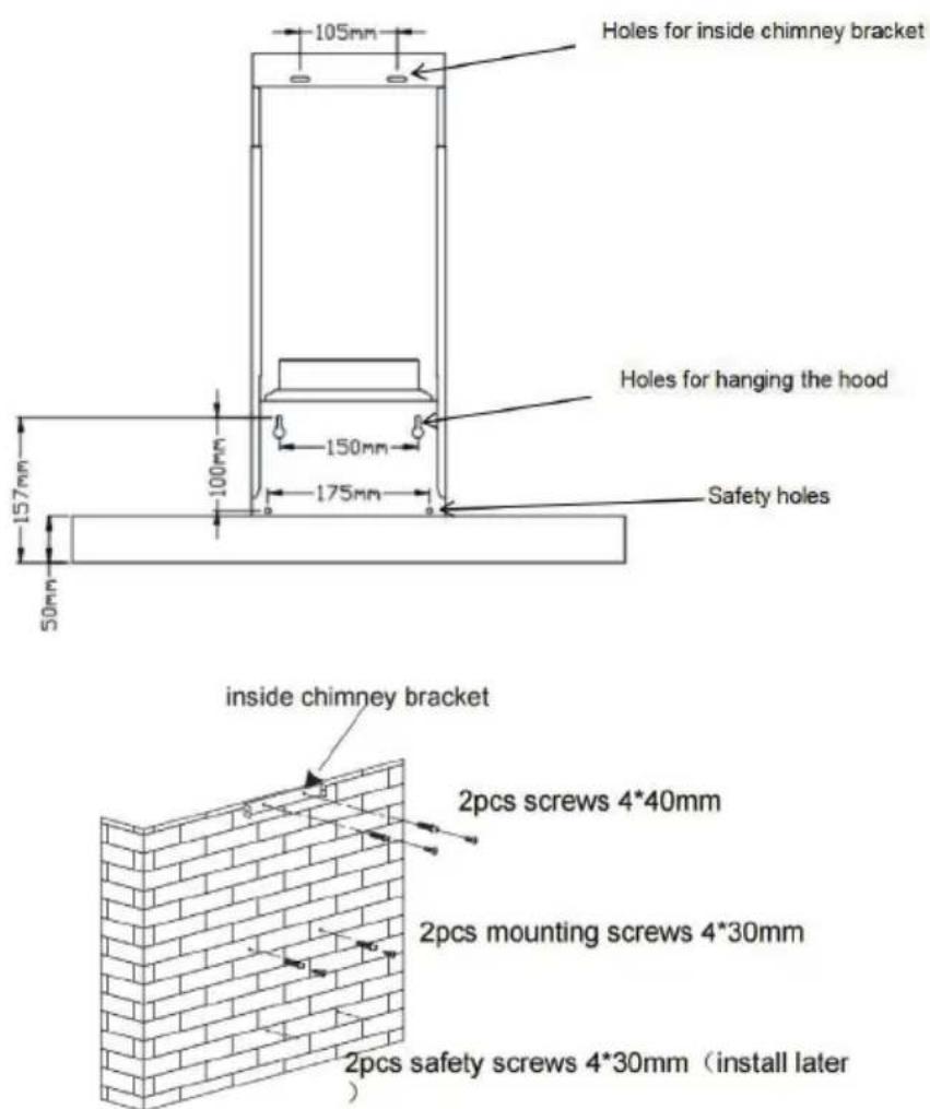
text_image
Holes for inside chimney bracket Holes for hanging the hood 105mm 150mm 175mm Safety holes 157mm 100mm 50mm inside chimney bracket 2pcs screws 4*40mm 2pcs mounting screws 4*30mm 2pcs safety screws 4*30mm (install later)Pic2
- Use 2pcs screws (4*8mm) to fix the outlet on the appliance top, and then fix expansionpipeontotheoutletwithcabletie.Seepic3.Note:theexpansionpipe isnotincludedintheproduct.
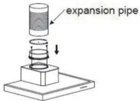
text_image
expansion pipe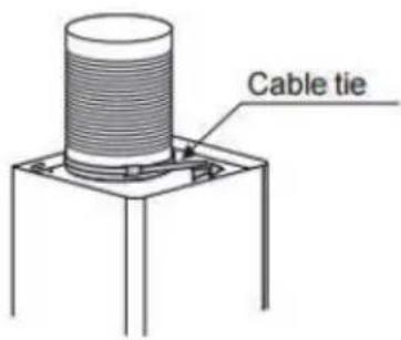
text_image
Cable tiePic3
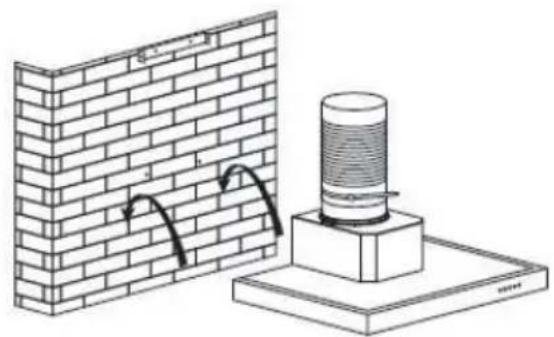
- Hangtheapplianceontothemountingscrews. Seepic4.
natural_image
Technical illustration of a brick wall and a cylindrical installation base (no text or symbols)Pic4
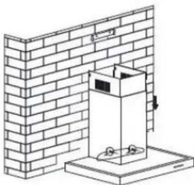
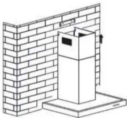
- Install the chimney assembly onto the appliance and lead the expansion pipeto outside, then use 2 pcs safety screws (4* 30mm) to fix the cooker hood on the wall. Note: Thetwosafetyvents are positioned on the backhousing, with diameter of 6 mm. Seepic 5 & 6.
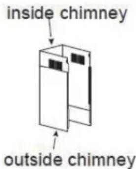
text_image
inside chimney outside chimneyPic5
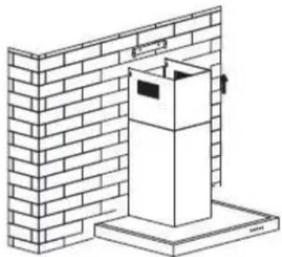
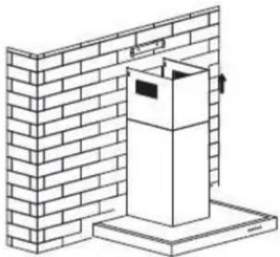
- Pulluptheinsidechimneyuntilreachtheinsidechimneybracketandfixthem with 2pcs screws (4*8mm). See pic 7.
natural_image
Technical line drawing of a brick wall and a box installation (no text or symbols)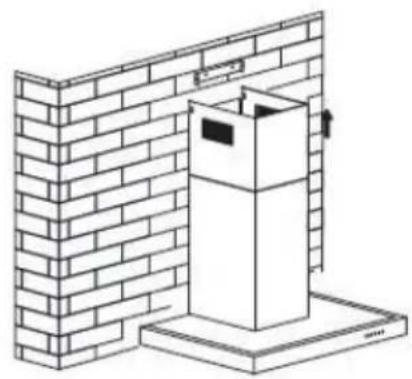
natural_image
Isometric line drawing of a brick wall with a box and base, no text or symbols presentPic6Pic7
HINTS FOR EXHAUST DUCT INSTALLATION
The following rules must be strictly followed to obtain optimalaire extraction:
- Keepexpansionpipeshortandstraight.
- Donotreducethesizeorrestricttheexpansionpipe.
- When using the expansion pipe always install the pipe pulled tauttominimize pressure loss.
- Failuretoobservethesebasicinstructionswillreducetheperformanceandincrease noiselevelsofthecookerhood.
- Anyinstallationworkmustbecarriedoutbyaqualifiedelectricianorcompetent person.
- Donotconnecttheductingsystemofthehoodtoanyexistingventilationsystem whichisbeingusedforanyotherappliance,suchaswarmertube,gastube,hotwind tube.
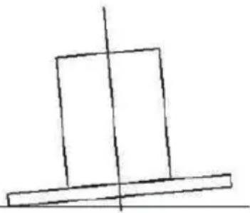
- The angle of the bend of the expansion pipes should not be less than 120^ ; you must direct the pipe horizontally, or, alternatively, the pipes should group from the initial point and should be led to an outer wall.
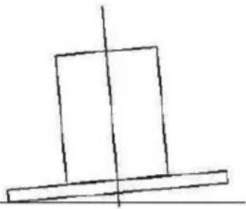
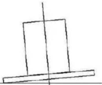
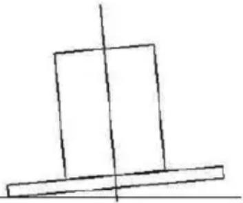
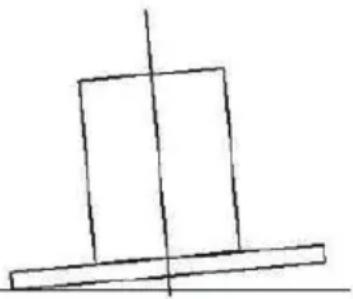
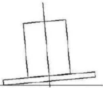
•Aftertheinstallation, makesurethatthecookerhoodisleveltoavoidgrease collectionatonend. - Ensuretheexpansionpipeselectedforinstallationcomplieswithrelevantstandards andisfireretardant.

natural_image
Simple geometric diagram with a vertical line intersecting a rectangle (no text or symbols)Right
natural_image
Simple line drawing of a rectangular block with a vertical axis and a horizontal base (no text or symbols)wrong
HINTS FOR EXHAUST DUCT INSTALLATION
The following rules must be strictly followed to obtain optimalaire extraction:
- Keepexpansionpipeshortandstraight.
-
Donotreducethesizeorrestricttheexpansionpipe.
-
When using the expansion pipe always install the pipe pulled tauttominimize pressure loss.
- Failuretoobservethesebasicinstructionswillreducetheperformanceandincrease noiselevelsofthecookerhood.
- Anyinstallationworkmustbecarriedoutbyaqualifiedelectricianorcompetent person.
- Donotconnecttheductingsystemofthehoodtoanyexistingventilationsystem whichisbeingusedforanyotherappliance,suchaswarmertube,gastube,hotwind tube.
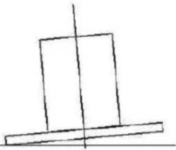
- The angle of the bend of the expansion pipes should not be less than 120^ ; you must direct the pipe horizontally, or, alternatively, the pipes should group from the initial point and should be led to an outer wall.
- Aftertheinstallation, makesure that the cookerhood is level to avoid grease collection at on end.
- Ensuretheexpansionpipeselectedforinstallationcomplieswithrelevantstandards andisfireretardant.
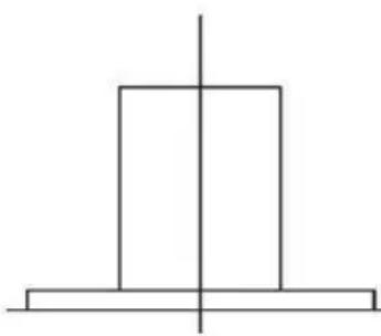
natural_image
Simple geometric diagram with two rectangles and a vertical line crossing through the center (no text or symbols)Right
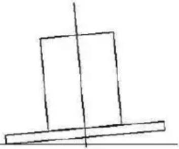
natural_image
Simple line drawing of a tilted rectangular block with a vertical centerline (no text or symbols)wrong
Electrical Installation
All installation must be carried out by a competent person or qualified electrician.
Beforeconnectingthemainssupplyensurethatthemainsvoltagecorrespondstothe voltageontheratingplate.
DirectConnection
The appliance must be connected directly to them, mains using an omnipolar circuit breaker with a
minimumopeningof3mmbetweenthecontacts.
The installermustensurethatthecorrectelectricalconnectionhasbeenmadeand thatitcomplieswiththewiringdiagram.
Thecablemustnotbebentorcompressed.
Regularlycheckthepowerplugandpowercordfordamage.Ifthesupplycordis damaged,itmustbereplacedbyaspecialcordorassemblyavailablefromthe manufactureroritsserviceagent.
WARNING: ThisisaClasslapplianceandMUSTbeearthed
This appliance is supplied with a 3 core main cable coloured as follows:
Brown=LorLive
Blue=NorNeutral
GreenandYellow=EorEarth

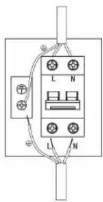
text_image
L N L NWARNING:

text_image
Yellow triangular warning sign with black exclamation mark symbolForsafetyreason,pleaseuseonlythesame sizeoffixingormountingscrewsswhichare recommendedinthisinstructionmanual.
➢ Failuretoinstallthescrewsorfixingdevicein accordancewiththeseinstructionsmayresultin electricalhazards.
Start Using Your Cooker Hood
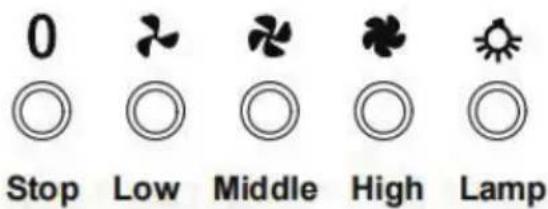
Push button
1) Pushthestopbutton, and themotorwillstop.
2) Pushthelowbutton, and themotorwillrunatlowspeed.
3) Pushthemiddlebutton, and the motor will run at midspeed.
4) Push the high button, and them motor will run at high speed.
5) Pushthelightbuttonandthetwolightswillilluminate.Pushitagainandthelight willturnoff.
text_image
0 Stop Low Middle High LampTROUBLESHOOTING
| Fault Possible Cause Solution | ||
| Lighton,butmotor doesnotwork | Fanswitch turned off | Selectafanswitchposition. |
| Fanswitchfailed | Contactservicecenter. | |
| Motorfailed | Contactservicecenter. | |
| Lightdoesnot work,motordoes notwork | Housefusesblown | Reset/Replacefuses. |
| Mainspowercableislooseor disconnected | Refitmainspowercableto poweroutlet.Switchpoweroutleton. | |
| Oilleakage | Onewayvalveandtheoutlet arenottightlysealed | Takedowntheonewayvalve andsealwithsealant. |
| Leakagefromtheconnectionof chimneyandcover | Takechimneydownandseal. | |
| Lightsnotworking | Brokenorfaultybulbs | Replaceblubsasperthis instruction. |
| Insufficientsuction | Thedistancebetweenthe cookerhoodandthegastopis toofar | Refitthecookerhoodtothe correctdistance. |
| TheCookerhood inclines | Thefixingscrewisnottight enough | Tightenthehangingscrewand makeithorizontal. |
NOTE:
Anyelectricalrepairstothisappliancemustconformtoyourlocal,stateand federallaws.Pleasecontacttheservicecentreifinanydoubtbefore
undertakinganyoftheabove.Alwaysdisconnecttheunitfromthepowersourcewhen openingtheunit.
MAINTENANCE AND CLEANING
Caution:
- Beforemaintenanceorcleaningiscarriedout,thecookerhoodshouldbe disconnectedfromthemainspowersupply.Ensurethatthecookerhoodisswitched offatthewallsocket.
- Externalsurfacesaresusceptibletoscratchesandabrasions, sopleasefollow the cleaninginstructionstoensurethebestpossibleresultisachievedwithoutdamage.
GENERAL
Cleaningandmaintenancesshouldbecarriedoutwiththeappliancecoldespecially
whencleaning.Avoidleavingalkalineoracidsubstances(lemonjuice,vinegaretc.)on thesurfaces.
STAINLESSSTEEL
Thestainlesssteelmustbecleanedregularly(e.g.weekly)toensurealonglife expectancy.Drywithacleansoftcloth.Aspecializedstainlesssteelcleaningfluidmay beused.
NOTE:
Ensure that wiping is done along with the grain of the stainless steel to prevent any unsightly crisscrossScratching patterns from appearing.
CONTROLPANELSURFACE
Theinlaycontrolpanelcanbecleanedusingwarmsoapywater.Ensuretheclothis cleanandwellwrungbeforecleaning.Useadrysoftclothtoremoveanyexcess moistureleftaftercleaning.
Important
Usingneutraldetergentsandavoidusingharshcleaningchemicals,stronghousehold detergentsorproductscontainingabrasives,asthiswillaffecttheappearanceofthe applianceandpotentiallyremoveanyprintingofartworkonthecontrolpanelandwill voidmanufactureswarrantee.
GREASEMESH FILTERS
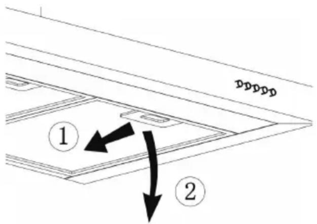
Themeshfilterscanbecleanedbyhand.Soakthemforabout3minutesinwaterwithamilddetergentandthenbrushitgentlywithasoftbrush.Donotapplytoomuchpressuresoastoavoidanydamagetoit.(Leavetodrynaturallyoutofdirectsunlight).
Filters should bewashed separately to crockery and kitchen utensils. It is advisable not to userinseaid.
text_image
① ②INSTALLINGGREASEMESHFILTERS
- Toinstallfiltersforthefollowingfoursteps:
-Anglethefilterintotheslotsatthebackofthehood.
-Pushthebuttononthehandleofthefilter.
-Releasethehandleoncethefilterfitsintoarestingposition.
-Repeattoinstallallfilters.
CARBONFILTER-notincludedintheproduct
Activatedcarbonfiltercanbeusedtotrapodors. Normally the activated carbonfilter should be changed every 3 to 6 months according to your cooking habits. The installation procedure of activated carbon filter is as below:
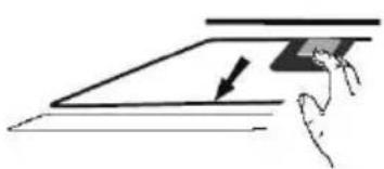
- Removethegreasefilter.
natural_image
Simple line drawing of a hand holding a rectangular object over a flat surface, with an arrow indicating direction (no text or symbols)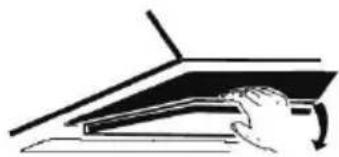
natural_image
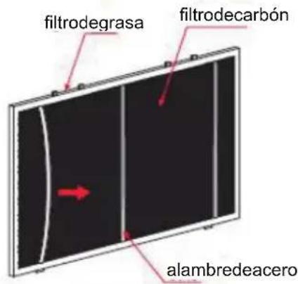
Simple line drawing of a hand pressing down on a laptop (no text or symbols)- Takeaway the steel wire with proper strength, aspic 1 shown.
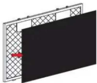
- Seepic2, replacethenewcarbonfilterontothegreasefilter.
4.Fixtheproperly-adjustedcarbonfilterwiththesmallsteelwire. - Reinstall the grease filter.
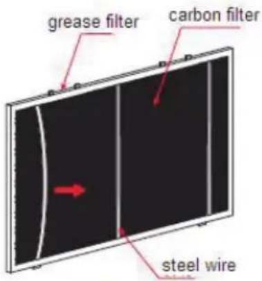
text_image
grease filter carbon filter steel wirePic1Pic2
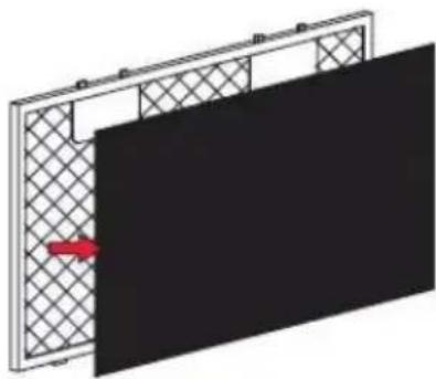
natural_image
Diagram of a panel with a red arrow pointing to a black panel, showing no text or symbols.NOTE:
- Make sure the filter is securely locked. Otherwise, it would loosen and cause danger.
- Whenactivatedcarbonfilterattached,thesuctionpowerwillbelowered.
BULBREPLACEMENT
Important:

Thebulbmustbereplacedbythemanufacturer,its serviceagentorsimilarlyqualifiedpersons.
* Always switchchofftheelectricity supply before carrying out any operations on the appliance. When handling bulb, makes sure it has completely cooled down before any direct contact with hands.
Whenhandlingbulbsholdwithaclothorglovesto ensureperspirationdoesnotcomeincontactwith thebulbasthiscanreducethelifeofthebulb.
Note:
- Before Replacement light that the cooker hood can be isolated from the supply mainsbymeansofaplugoranall-poleswitch.
● Protect against danger when changing lights, such as wearing gloves.
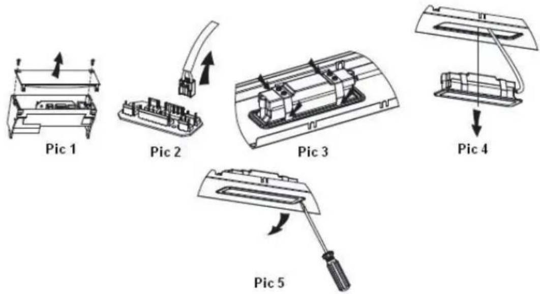
Changingthelights:
▶ Removethegreasefilter.
Findoutthejunctionbox,unscrewthescrewsonthejunctionboxcover,thentake downthejunctionboxcover(Ifthereiswirepressingplatewhichpressedthelight wire,thewirepressingplateneedstobedismantledfirst).Seepic1.
Findouttheterminalofthelightconnectingwireandpullitout.Seepic2.
Way1.UseatoolorthehandtopressthespringsplinterofbothsidesofLEDlight totheinside,untilthelightispressedout,seepic3.Thenslightlypullthelight connectingwireout,seepic4.
Way2. UsestraightscrewdrivertoprizeuptheLEDlightbottomedge,seepic5, thenslightlypulloutthelightconnectingwire,seepic4.
•ILCOSDcodeforthislampis:DBS-2/65-H-120/33
-LEDmodules-rectanglelamp
-Maxwattage:1x2W
-Voltagerange:AC110-240V
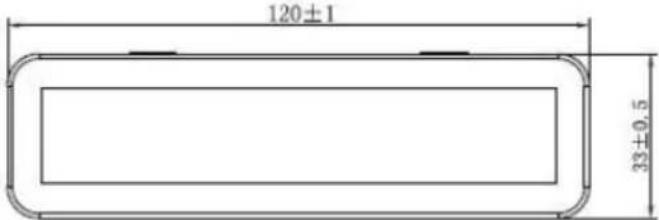
text_image
120±1 33±0.5-Dimensions:
ENVIRONMENTAL PROTECTION:
natural_image
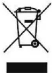
Symbol of a trash bin with crossed lines indicating no waste or restriction, plus a solid black rectangle below (no text or labels)Thisproductismarkedwiththesymbolontheselectivesortingof wasteelectronicequipment. Thismeansthatthisproductmustnot bedisposedofwithhouseholdwastebutmustbesupportedbya systemofselectivecollectioninaccordancewithDirective 2012/19/EU.Itwillthenberecycledordismantledtominimize impactsontheenvironment,electricalandelectronicproductsare potentiallydangerousfortheenvironmentandhumanhealthdueto thepresenceofhazardoussubstances.Formoreinformation,please contactyourlocalorregionalauthorities.
NOTE:
The following show show to reduce total environmental impact (e.g. energy use) of the cooking process).
(1) Install the cooker hood in a proper place where there is sufficient ventilation.
(2)Cleanthecookerhoodregularlysoasnottoblocktheairway.
(3)Remembertoswitchoffthecookerhoodlightaftercooking.
(4) Remembertoswitchoffthecookerhoodaftercooking.
INFORMATIONFORDISMANTLING
Donotdismantletheapplianceinawaywhichisnotshownintheusermanual. The appliancecouldnotbedismantledbyuser.Attheendoflife,theapplianceshould notbedisposedofwithhouseholdwaste.CheckwithyourLocalAuthorityorretainer forrecyclingadvice.
natural_image
Technical line drawings of a ceiling structure with ventilation grilles and mounting brackets (no text or symbols)Índice
natural_image
Illustration of a desk lamp illuminating a steaming lamp with a black X-shaped light fixture (no text or symbols)Hacer siempre:
text_image
Prohibition sign with two figures holding a diagonal line, symbolizing no smoking or prohibitionsupervisión.
Hacer siempre:
text_image
Technical diagram showing mechanical assembly with numbered components and directional arrows indicating motion or forceINSTALACIÓN
natural_image
Diagram of airflow around a mechanical structure with directional arrows (no text or symbols)natural_image
Diagram showing a brick wall and a cylindrical object mounted on a base, labeled 'Imagen4' (no text or symbols on the diagram itself)natural_image
Diagram of a brick wall with a box and support structure, showing structural details without any text or symbols.Imagen6
natural_image
Illustration of a brick wall with a box and upward arrow, no text or symbols presentImagen7
natural_image
Simple geometric diagram with a vertical line intersecting a rectangle (no text or symbols)Correcto
natural_image
Simple line drawing of a rectangular block with a vertical axis and horizontal base (no text or symbols)incorrecto
natural_image
Simple geometric diagram with a vertical line intersecting a rectangle (no text or symbols)Correcto
natural_image
Simple line drawing of a tilted rectangular object with a vertical axis intersecting it (no text or symbols)incorrecto
text_image
Yellow triangular warning sign with black exclamation mark symbolnatural_image
Simple line drawing of a hand pressing down on a flat surface with a downward arrow (no text or symbols)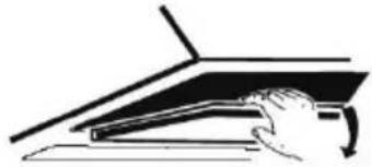
natural_image
Simple line drawing of a hand pressing down on a laptop keyboard (no text or symbols)2.Retireelalambredeaceroconlaresistenciaadecuada,comosemuestraenlaimagen1.
3.Coloqueelnuevofiltrodecarbónenelfiltrodegrasa,consultelaimagen2.
4.Fijeelfiltrodecarbóndebidamenteajustadoconelalambredeaceropequeño.
5.Vuelvaacolocarelfiltrodegrasa.
text_image
filtrodegrasa filtrodecarbón alambredeaceroImagen1
natural_image
Diagram showing a panel with grid pattern and a red arrow pointing to a black panel (no text or symbols)Imagen2
NOTA:
natural_image
Symbol of a trash bin crossed with no text or numbers, representing waste sorting or disposal (no text present)natural_image
Technical line drawings of a two-tiered kitchen or ventilation unit (no text or symbols)Sommaire
natural_image
Illustration of a laboratory setup with a lamp, test tube, and gas collection bottle (no text or symbols)text_image
Prohibition sign with two pictograms showing a person and child against a diagonal line, indicating no prohibition or rejection.Consignes à
respecter
absolument :
INSTALLATION (ÉVACUATION VERS
L' EXTÉRIEUR)
MONTAGE DU CLAPET ANTIRETOUR
text_image
Technical diagram showing mechanical assembly with numbered components and directional arrows indicating motion or forceINSTALLATION
natural_image
Diagram of airflow around a mechanical component with directional arrows indicating movement (no text or symbols)natural_image
Technical illustration of a brick wall and a cylindrical mechanical component mounted on a base (no text or symbols)Fig.4
natural_image
Technical line drawing of a brick wall and a vertical support structure with mounting base (no text or symbols)Fig.6
natural_image
Diagram of a brick wall with a box and support structure, no text or symbols presentFig.7
CONSEILS POUR L'INSTALLATION DU CONDUIT
D' ÉVACUATION
natural_image
Simple geometric diagram with a vertical line intersecting a rectangle (no text or symbols)Correct
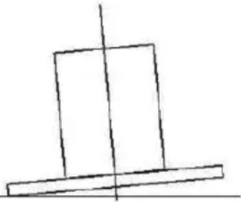
natural_image
Simple line drawing of a tilted rectangular object with a vertical axis intersecting it (no text or symbols)incorrect
CONSEILS POUR L'INSTALLATION DU CONDUIT
D' ÉVACUATION
natural_image
Simple geometric diagram with two rectangles and a vertical line intersecting at the center (no text or symbols)Correct
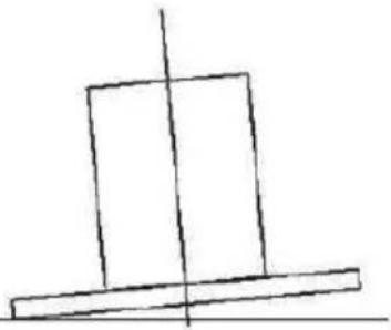
natural_image
Simple line drawing of a tilted rectangular object with a vertical centerline (no text or symbols)incorrect
text_image
Yellow triangular warning sign with black exclamation mark symbolnatural_image
Simple line drawing of a hand holding a rectangular object with an arrow, no text or symbols present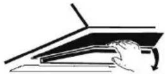
natural_image
Simple line drawing of a hand pressing down on a laptop (no text or symbols)natural_image
Diagram of a panel with grid pattern and a red arrow pointing to a black panel (no text or symbols)Fig.2
REMARQUE:
REPLACEMENTDELALAMPE
Important:

natural_image
Diagram of a mechanical assembly with a downward arrow indicating force or direction (no text or symbols present)PROTECTION DE L'ENVIRONNEMENT :
natural_image
Symbol of a trash bin with crossed lines indicating no waste, and a solid black rectangle below (no text or labels)INFORMATIONSRELATIVESAUDÉMONTAGE
natural_image
Line drawing of a kitchen ventilation duct with ventilation grilles and ventilation grilles (no text or symbols)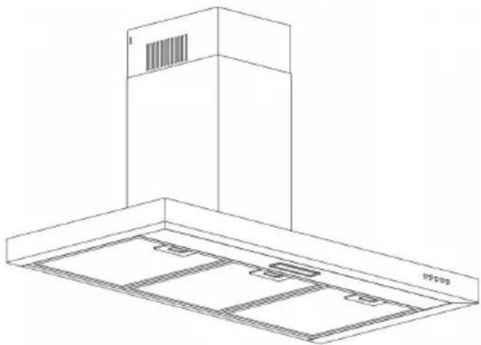
natural_image
Isometric line drawing of a ceiling structure with ventilation grilles and a barcode cover (no text or symbols)Conteúdo
natural_image
Illustration of a lamp illuminating a small object with a crossed-out black X mark (no text or symbols)Afazersempre:
text_image
Prohibition sign with two figures holding a diagonal line, indicating no smoking or anti-smokingAfazer sempre
text_image
Technical diagram showing mechanical assembly with numbered components and a close-up of a component detailINSTALAÇÃO
natural_image
Diagram of a mechanical or fluidic system with directional arrows indicating flow or movement (no text or symbols)natural_image
Diagram showing a brick wall and a cylindrical object mounted on a base, labeled 'Imagem4' (no text or symbols on the diagram itself)natural_image
Simple geometric diagram with a vertical line intersecting a rectangle (no text or symbols)Correto
natural_image
Simple line drawing of a tilted rectangular object with a vertical centerline (no text or symbols)errado
natural_image
Simple geometric diagram with a vertical line intersecting a rectangle (no text or symbols)Correto
natural_image
Simple line drawing of a tilted rectangular object with a vertical centerline (no text or symbols)errado
Instalaçãoelétrica
natural_image
Two-step diagram showing hand positioning of a rectangular object on a flat surface, with arrows indicating direction (no text or symbols)natural_image
Diagram showing a panel with grid pattern and a red arrow pointing to a black panel (no text or symbols)Imagem2
NOTA:
natural_image
Symbol of a trash bin with crossed lines indicating no waste, and a solid black rectangle below (no text or labels)natural_image
Technical line drawings of a two-tiered kitchen canopy with ventilation grilles and ventilation ducts (no text or symbols)Inhalt
text_image
Prohibition sign with two figures holding hands, no text presentImmer tun:
text_image
Technical diagram showing mechanical assembly with numbered components and a close-up of a spherical component with internal structure.INSTALLATION
natural_image
Diagram of airflow around a mechanical component with directional arrows indicating movement (no text or symbols)natural_image
Technical illustration of a brick wall and a cylindrical device mounted on a base (no text or symbols)Abb.4
natural_image
Technical line drawing of a brick wall and a vertical support structure with mounting base (no text or symbols)Abb.6
natural_image
Diagram of a brick wall with a box and directional arrow, no text or symbols presentAbb.7
HINWEISE ZUR INSTALLATION DER ABLUFTKANÄLE
natural_image
Simple geometric diagram with a vertical line intersecting a rectangle (no text or symbols)Rechts
natural_image
Simple line drawing of a tilted rectangular object with a vertical centerline (no text or symbols)Falsch
HINWEISE ZUR INSTALLATION DER ABLUFTKANÄLE
natural_image
Simple geometric diagram with a vertical line intersecting a rectangle (no text or symbols)Rechts
natural_image
Simple line drawing of a tilted rectangular object with a vertical centerline (no text or symbols)Falsch
text_image
Warning sign with yellow triangle and black exclamation mark, commonly used for safety alertsnatural_image
Diagram of a panel with grid pattern and a red arrow pointing to a black panel (no text or symbols)Abb.2