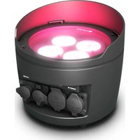
DROP P4 - Lighting Cameo - Free user manual and instructions
Find the device manual for free DROP P4 Cameo in PDF.


| Product type | Outdoor LED wash projector |
| Brand | Cameo |
| Model | DROP P4 |
| Number of LEDs | 4 |
| LED type | RGBWA+UV 15 W |
| Beam angle | 22° (without diffuser), 32° and 45° with included diffusers |
| Luminous flux | 1100 lm |
| Illuminance (at 1 m) | 6,750 lx |
| CRI (white) | > 79 |
| Power supply | 100-240 V AC, 50/60 Hz, 45 W |
| Power connector | TRUE1 (input) and TRUE1 (output, max. 11 A) |
| Protection | IP65 |
| DMX mode | 3, 4, 6, 7, 13 (×2), 20 channels |
| Wireless reception | W-DMX™ built-in |
| Display | OLED screen |
| Dimensions (W × H × D, without bracket) | 186 × 170 × 170 mm |
| Weight | 2.8 kg |
| Operating temperature | 0 °C to 40 °C |
| Cooling | Convection (passive) |
| Housing material | Metal (black) |
| Standalone functions | Color mixing, macros, automatic programs, loop, user colors, master/slave |
| Included accessories | TRUE1 power cable, 2 diffusers (32° and 45°), mounting bracket |
| Cleaning | Dry cloth; do not use liquids |
| Safety | Do not look directly into the beam; hot surface after operation; installation by qualified personnel |
Frequently Asked Questions - DROP P4 Cameo
User questions about DROP P4 Cameo
0 question about this device. Answer the ones you know or ask your own.
Ask a new question about this device
Download the instructions for your Lighting in PDF format for free! Find your manual DROP P4 - Cameo and take your electronic device back in hand. On this page are published all the documents necessary for the use of your device. DROP P4 by Cameo.
USER MANUAL DROP P4 Cameo
natural_image
Exterior view of a black circular power light fixture with pink ambient lighting (no text or symbols visible)DROP P4
OUTDOOR UPLIGHT RGBWA+UV WITH W-DMX™
CLDROPP4
CONTENTS / INHALTSVERZEICHNIS / CONTENU / CONTENIDO / TREŚĆ / CONTENUTO
ENGLISH
SAFETY INFORMATION 3
INTRODUCTION
CONNECTIONS, OPERATING AND DISPLAY ELEMENTS 5
OPERATION
IR REMOTE CONTROL (optional) 14
DIFFUSERS
SET-UP AND INSTALLATION 16
DMX TECHNOLOGY 17
TECHNICAL DATA 18
MANUFACTURER'S DECLARATIONS 19
DEUTSCH
This device was developed and produced under the highest standards of quality in order to ensure smooth operation for many years. Please read these operating instructions carefully so that you can use your new Cameo Light product quickly and optimally. You can find more information on Cameo Light on our website WWW.CAMEOLIGHT.COM.
SAFETY INFORMATION
- Please read through these instructions carefully.
- Store all information and instructions in a secure location.
- Follow the instructions.
- Heed all warnings. Do not remove any safety warnings or other information from the device.
- Use the device only in the intended manner.
- Use only stable and suitable stands and/or mounts (for fixed installations). Make sure that wall mounts are properly installed and secured. Make sure that the device is securely installed and will not fall.
- During installation, heed all safety provisions that apply in your country.
- Do not install and operate the device in the vicinity of heaters, heat reservoirs, ovens, or other heat sources. Make sure that the device is installed in such a way that it is sufficiently cooled and will not overheat.
- Do not place any ignition sources, e.g. candles, on the device.
- Do not block the ventilation slits.
- The device was designed to be used only in interior spaces, do not operate the device in the direct vicinity of water (this does not apply to specialty outdoor devices - in this case, please note the special instructions given in the following). Do not bring the device into contact with combustible materials, fluids, or gases.
- Make sure that no water can drop or splash into the device. Do not place any containers filled with fluids, such as vases or drinking vessels, onto the device.
- Ensure that no objects can fall into the device.
- Operative the device using only those accessories recommended and specified by the manufacturer.
- Do not open the device, and do not modify it.
- After connecting the device, inspect all cable paths in order to avoid damage or accidents, such as those caused by tripping over said cables.
- During transport, ensure that the device will not fall and potentially cause material damage and personal harm.
- If your device no longer functions properly, fluids or objects have made their way into the device interior, or the device is otherwise damaged, switch it off immediately and remove it from the power outlet (provided the device is active). This device is to be repaired only by authorized specialists.
- Use a dry towel to clean the device.
- Follow all laws on disposal applicable in your country. Please separate plastic and paper or cardboard when disposing of the packaging.
- Plastic bags must be kept out of reach of children.
FOR DEVICES CONNECTED TO A POWER SUPPLY:
- ATTENTION: If the device power cable is equipped with a ground pin, it must be inserted into an outlet with a grounding conductor. Never disable the grounding conductor of a power cable.
- Do not immediately switch on the device when it has been exposed to stark temperature deviations (for example after transport). Humidity and condensation could damage the device. Switch on the device only when it has reached room temperature.
- Before you connect the device to the outlet, first ensure that voltage and frequency of the power supply complies with the values given on the device. If the device has a voltage selector switch, connect the device to the outlet only if the device values comply with the values of the power supply. If the provided power cable or power adapter does not fit your power outlet, contact an electrician.
- Do not step on the power cable. Make sure that live cables, in particular those at the power socket or at the power adapter and the device socket, are not bent.
- With regard to the device cables, always make sure that the power cable or power adapter is always freely accessible. Always separate the device from the power supply when the device is not in use or when you would like to clean the device. Always unplug the power cable and power adapter from the power outlet using the plug or adapter, not the cord. Never touch the power cable and power adapter with wet hands.
- If possible, do not switch the device on and off quickly because this may impair the service life of the device.
- IMPORTANT INFO: Replace fuses only with fuses of the same type and value. If a fuse trips repeatedly, please contact an authorized service center.
- In order to completely separate the device from the power supply, remove the power cable or power adapter from the outlet.
- If your device is equipped with a Volex power cord, release the correct Volex device connector before removing the cord. However, this also means that the device may slide and fall when removing the power cord, which may cause personal harm and/or material damage. Therefore, always lay cables carefully.
- Remove the power cable and power adapter from the outlet when there is a risk of lighting or when you no longer want to use the device.
- The device may only be installed when it carries no voltage (separate the power plug from the power supply).
- Dust and other debris within the device may damage it. The device should be serviced or cleaned regularly by qualified specialists depending on the environmental conditions (dust, nicotine, smoke, etc.) in order to avoid overheating.
- The distance to combustible materials must be at least 0.5 m.
-
Power cables for powering multiple devices must have a core cross-section of at least 1.5 mm^2 . In the EU, lines must be H05VV-F or similar. Adam Hall provides suitable cables. Using these cables, you can connect multiple devices via the Power Out connection with the Power In connection of another device. Ensure that the total power consumption of all connected devices does not exceed the specified value (printed on the device). Be sure to keep power lines as short as possible.
-
The appliance is not to be used by persons (including children) with reduced physical, sensory or mental capabilities, or lack of experience and knowledge.
- Children must be instructed not to play with the device.
- If the power cord of the device is damaged, do not use the device. The power cord must be replaced by an adequate cable or assembly from an authorized service center.

CAUTION:
To reduce the risk of electric shock, do not remove cover (or back). There are no user serviceable parts inside. Maintenance and repairs should be exclusively carried out by qualified service personnel.
The warning triangle with lightning symbol indicates dangerous uninsulated voltage inside the unit, which may cause an electrical shock.

The warning triangle with exclamation mark indicates important operating and maintenance instructions.

Warning! This symbol indicates a hot surface. Certain parts of the housing can become hot during operation. After use, wait for a cool-down period of at least 10 minutes before handling or transporting the device.

Warning! This device is designed for use below 2000 metres in altitude.

Warning! This product is not intended for use in tropical climates.

Caution! Intense LED light source! Risk of eye damage. Do not look into the light source.
CAUTION! IMPORTANT INFORMATION ABOUT LIGHTING PRODUCTS!
- The product has been developed for professional use in the field of event technology and is not suitable as household lighting.
- Do not stare, even temporarily, directly into the light beam.
- Do not look at the beam directly with optical instruments such as magnifiers.
- Stroboscope effects may cause epileptic seizures in sensitive people! People with epilepsy should definitely avoid places where strobes are used.
INTRODUCTION
OUTDOOR UPLIGHT SPOTLIGHT WITH 4 X 15 W RGBWA+UV LEDS AND W-DMX™
CLDROPP4
CONTROL FUNCTIONS
• 3-channel, 4-channel, 6-channel 7-channel, 13-channel 1, 13-channel 2 and 20-channel DMX functions
• W-DMX™
- Standalone functions
- Control via IR remote control (remote control optionally available)
FEATURES
- 4 x 15 W RGBWA+UV LEDs
- Outdoor housing with IP65 protection class.
- 3-pin XLR connections. W-DMX receiver integrated
- OLED display
- Convection cooling
- Removable stand and mounting bracket for discreet uplift function
- Tilt adjustment screw
- 2 diffusers included.
CONNECTIONS, OPERATING AND DISPLAY ELEMENTS
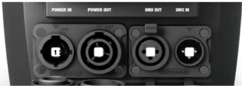
1 POWER IN
TRUE 1 compatible power input socket. Operating voltage 100–240 V AC/50–60 Hz. A suitable mains cable with IP65 plug is included. When not in use, always close with the appropriate rubber sealing cap.
2 POWER OUT
TRUE 1 compatible mains output socket for supplying power to additional Cameo headlights (for maximum output current, see label on back of housing). When not in use, always close with the appropriate rubber sealing cap.
3 DMX IN
Male IP65 3-pin XLR socket for connection to a DMX control device (e.g. DMX console) When not in use, always close with the appropriate rubber sealing cap.
4 DMX OUT
Female IP65 3-pin XLR socket for sending the DMX control signal. When not in use, always close with the appropriate rubber sealing cap.
PLEASE NOTE: To protect the input and output sockets from splash water in accordance with IP65 protection class, they must be correctly closed using the appropriate IP65 plugs or the rubber sealing caps must be used to close them.
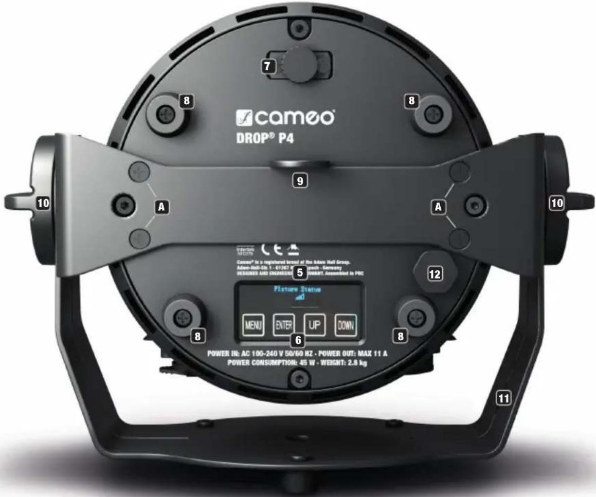
5 OLED DISPLAY
The OLED display shows the currently activated mode (main display 1), the spotlight status (main display 2 = W-DMX status), the menu items in the editing menu and the numerical value or operating mode in certain menu items. Switch between both main displays by briefly pressing ENTER and DOWN at the same time. The editing menu is accessible only from main display 1. If there is no input for approx. one minute, the display automatically returns to the main display. Note on the main display in DMX operating mode: As soon as the control signal is interrupted, the characters in the display begin to flash. When there is a control signal again, the flashing stops. Briefly pressing UP on the control panel when in the main display rotates the display by 180°.
6 TOUCH-SENSITIVE CONTROLS
MENU – Press MENU to access the editing menu. Press repeatedly to go back to the main display. Pressing MENU without confirming a value or status change with ENTER restores the previously confirmed value or status.
ENTER – Press ENTER to access the menu levels to make value changes and use the ENTER control field to access the submenus. Confirm value or status changes by pressing ENTER.
UP and DOWN – select individual menu items in the selection menu (DMX address, operating mode etc.) and in the submenus. Allow changes to the value in a menu item, such as the DMX address, as required.
Before changing device settings, ensure that the control panel is dry and clean, in order not to impair its functionality.
7 TILT
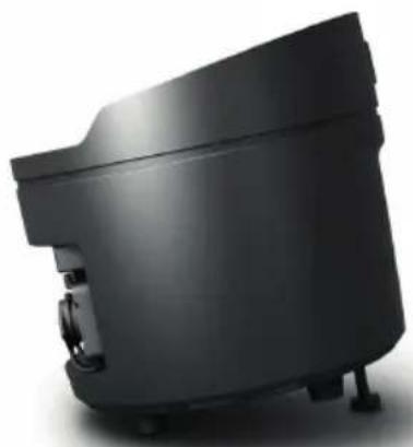
Knurled screw for the TILT feature for uplighting. Turn the screw outwards from the housing until you achieve the desired beam direction. The screw features a mechanical stop mechanism to prevent it from being completely removed from the housing. To be able to use the tilt function effectively and achieve a more discreet look, remove the mounting bracket by loosening the four screws A with a suitable tool.
8 RUBBER FEET
Four rubber feet on the underside of the spotlight ensure that it can be securely placed on suitable surfaces when used in uplight applications, while at the same time protecting the surface from scratches.
9 SECURING LUG
Securing lug for attaching the spotlight on truss installations. When installing on a truss, make sure that the mounting bracket is securely attached to the spotlight housing using the four fixing screws A.
10 GRIP SCREWS
The two grip screws are used for adjusting and fixing the stand and/or mounting bracket.
11 STAND OR MOUNTING BRACKET
The stand or mounting bracket can be removed to achieve a more inconspicuous look when using the spotlight as an uplight.
12 PRESSURE EQUALISATION ELEMENT
Pressure equalisation element to prevent condensation inside the housing. In order to ensure its proper function, the element must be protected from contamination.
INFRARED SENSOR
The infrared sensor for control via IR remote control (optionally available) is found on the front of the spotlight.
OPERATION
PLEASE NOTE
- As soon as the spotlight is switched on, the following are displayed in succession: "Software Update Please Wait..." (for service purposes only), "Welcome to Cameo", the model name and the software version. After this process, the spotlight is ready for operation and the previously activated operating mode is launched.
- The main display 1 is activated automatically if there is no input in the space of approximately one minute. Press MENU briefly to go up one level in the submenus.
- Briefly pressing UP on the control panel when in the main display rotates the display by 180^ .
- To quickly change a value (e.g. DMX start address), press and hold UP or DOWN.
- To reset the W-DMX module directly from main display 1 and put it in pairing standby, press and hold DOWN for about 3 seconds.
MAIN DISPLAY 1 DMX OPERATING MODE
The display shows the DMX address and current DMX start address (in the example: 001).
DMX Address
001
MAIN DISPLAY 1 STANDALONE MODE
The display shows the currently activated stand-alone mode.
Mode
Static
Mode
Color Macro
Mode
Auto
Mode
Loop
Mode
User Color
MAIN DISPLAY SLAVE MODE
The display shows Mode Slave.
Mode
Slave
MAIN DISPLAY 2 FIXTURE STATUS
The display shows the W-DMX status. Switch between both main displays by briefly pressing ENTER and DOWN at the same time. Main display 1 automatically appears again after approximately one second.
Fixture Status

W-DMXTM
To pair the W-DMX receiver with a W-DMX compatible transmitter, W-DMX must be activated (W-DMX On) in the receiver's menu under Wireless Settings. The Reset command must be also executed under the same menu item (select Reset and confirm with ENTER). The receiver is now in pairing standby and waiting for a pairing request from a transmitter. Start the pairing by selecting Link in the menu of the transmitter and then confirm; the pairing now takes place automatically. In the same way, several receivers can be paired to a transmitter either simultaneously or one after the other. A W-DMX connection is always maintained until the connection is disconnected by means of the Reset command in the receiver or the Unlink command in the transmitter, regardless of whether a device has been disconnected from the power supply in the meantime.
W-DMX™ STATUS RF SIGNAL STRENGTH
| W-DMX deactivated | W-DMX activated, not paired | W-DMX activated and paired, transmitter is switched off or out of range | W-DMX activated and paired, no DMX signal | W-DMX activated and paired, DMX signal available |

CONFIGURE DMX START ADDRESS
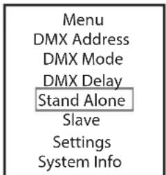
Starting from main display 1, press MENU to enter the main menu. Now use the controls UP and DOWN to select the menu item DMX address and confirm with ENTER. You can now configure the DMX start address with UP and DOWN (hold for rapid value change; highest value depends on activated DMX mode). Confirm by pressing ENTER.
| Menu |
| DMX Address |
| DMX Mode |
| DMX Delay |
| Stand Alone |
| Slave |
| Settings |
| System Info |
DMX Address 001 - 510
CONFIGURE DMX MODE
Starting from main display 1, press MENU to enter the main menu. Now use the controls UP and DOWN to select the menu item DMX mode and confirm with ENTER. Again use UP and DOWN to select the desired DMX mode and confirm with ENTER. Tables with the channel assignment of the different DMX modes can be found in these instructions under DMX CONTROL.
| MenuDMX AddressDMX ModeDMX DelayStand AloneSlaveSettingsSystem Info |
DMX Mode
3 CH 4 CH 6 CH 7 CH
13CH01 13CH02 20 CH
DMX DELAY
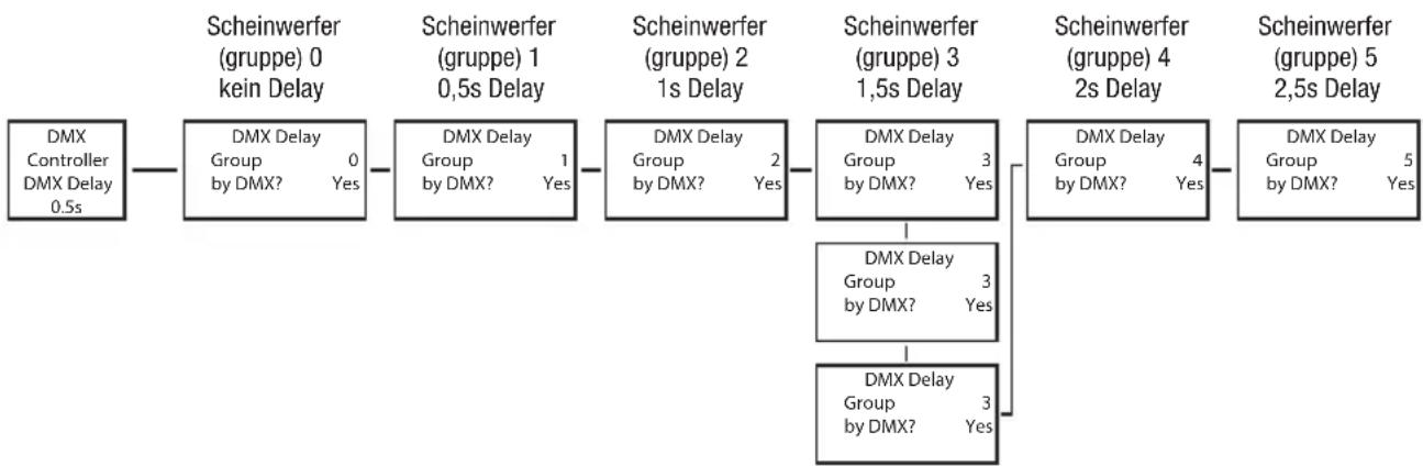
The DMX Delay function is a simple way to create a running light effect with a large number of spotlights that are all the same model and that are all running the same software version. This is otherwise only achievable with a suitable DMX controller and time-consuming programming. All the spotlights used in this are set to the same DMX operating mode and controlled via the same DMX start address. The delay time (DMX signal delay) can be manually set on each spotlight with different delay times (DMX Delay by DMX? No) or with the same delay time for all spotlights via a connected DMX controller on a specially reserved DMX channel (DMX Delay by DMX? Yes). Starting from the main display, press MENU to enter the main menu. Now use UP and DOWN to select the menu item DMX Delay and confirm with ENTER. Again use UP and DOWN to select the desired submenu item, confirm with ENTER and set the value or status accordingly. Confirm all entries with ENTER.
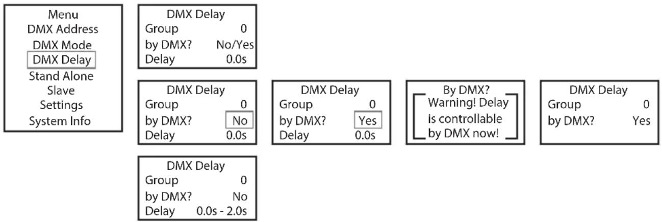
flowchart
graph TD
    A["Menu\nDMX Address\nDMX Mode\nDMX Delay\nStand Alone\nSlave\nSettings\nSystem Info"] --> B["DMX Delay\nGroup 0\nby DMX? No/Yes\nDelay 0.0s"]
    B --> C["DMX Delay\nGroup 0\nby DMX? No\nDelay 0.0s"]
    C --> D["DMX Delay\nGroup 0\nby DMX? Yes\nDelay 0.0s"]
    D --> E["By DMX?\nWarning! Delay\nis controllable\nby DMX now!"]
    E --> F["DMX Delay\nGroup 0\nby DMX? Yes"]
    F --> G["DMX Delay\nGroup 0\nby DMX? No\nDelay 0.0s - 2.0s"]
Assign the spotlights to the desired groups (maximum number of groups 6), whereby several spotlights can be assigned to one group. The group number is also the factor by which the set delay time is multiplied (see setup example).
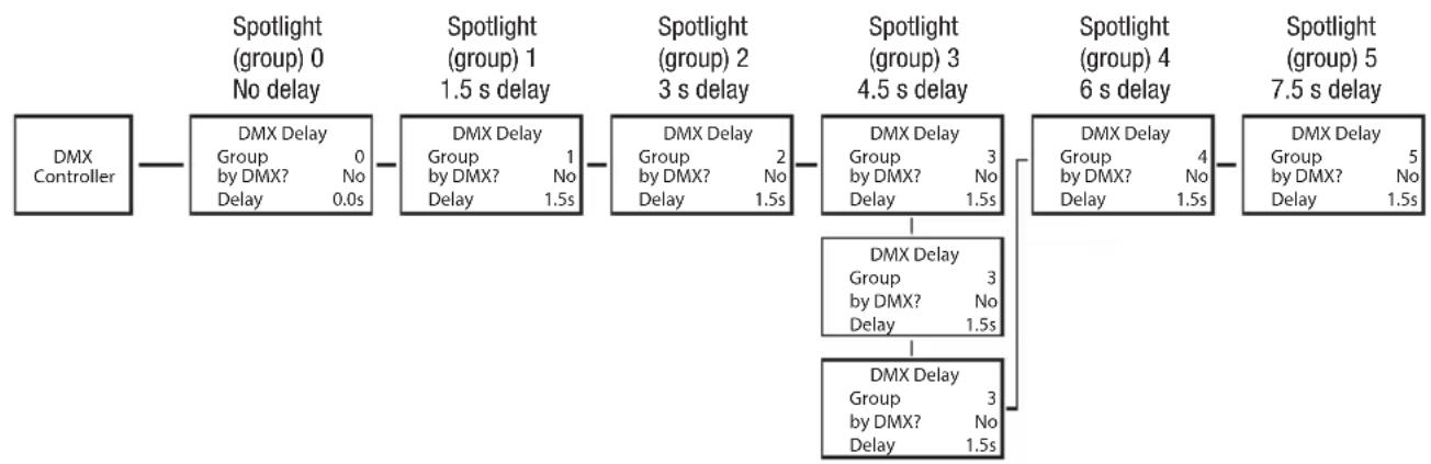
flowchart
graph LR
    A["DMX Controller"] --> B["DMX Delay Group 0\nby DMX? No\nDelay 0.0s"]
    B --> C["DMX Delay Group 1\nby DMX? No\nDelay 1.5s"]
    C --> D["DMX Delay Group 2\nby DMX? No\nDelay 1.5s"]
    D --> E["DMX Delay Group 3\nby DMX? No\nDelay 1.5s"]
    E --> F["DMX Delay Group 4\nby DMX? No\nDelay 1.5s"]
    F --> G["Spotlight (group) 0\nNo delay"]
    G --> H["Spotlight (group) 1\n1.5 s delay"]
    H --> I["Spotlight (group) 2\n3 s delay"]
    I --> J["Spotlight (group) 3\n4.5 s delay"]
    J --> K["Spotlight (group) 4\n6 s delay"]
    K --> L["Spotlight (group) 5\n7.5 s delay"]
    L --> M["Spotlight (group) 5\n7.5 s delay"]
    M --> N["DMX Delay Group 5\nGroup by DMX? No\nDelay 1.5s"]
    N --> O["DMX Delay Group 3\nGroup by DMX? No\nDelay 1.5s"]
    O --> P["DMX Delay Group 3\nGroup by DMX? No\nDelay 1.5s"]
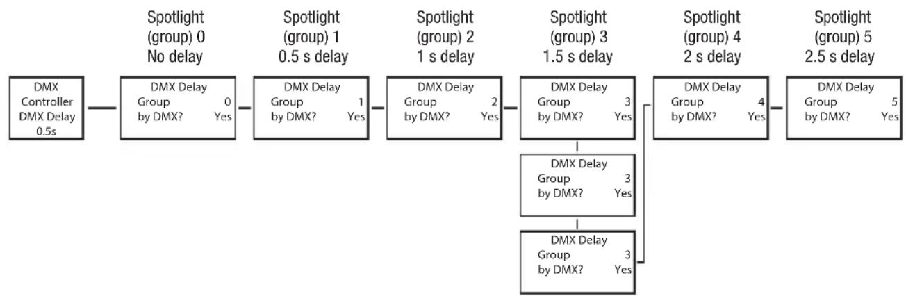
flowchart
graph LR
    A["DMX Controller DMX Delay 0.5s"] --> B["DMX Delay Group 0 by DMX? Yes"]
    B --> C["DMX Delay Group 1 by DMX? Yes"]
    C --> D["DMX Delay Group 2 by DMX? Yes"]
    D --> E["DMX Delay Group 3 by DMX? Yes"]
    E --> F["DMX Delay Group 4 by DMX? Yes"]
    F --> G["DMX Delay Group 5 by DMX? Yes"]

    subgraph Spotlight (group) 0 No delay
        B
        C
        D
    end

    subgraph Spotlight (group) 1 0.5 s delay
        C
        D
    end

    subgraph Spotlight (group) 2 1 s delay
        D
    end

    subgraph Spotlight (group) 3 1.5 s delay
        E
    end

    subgraph Spotlight (group) 4 2 s delay
        F
    end

    subgraph Spotlight (group) 5 2.5 s delay
        G
    end
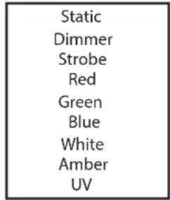
STANDALONE MODE STATIC
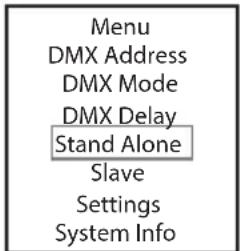
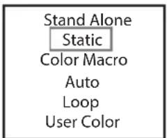
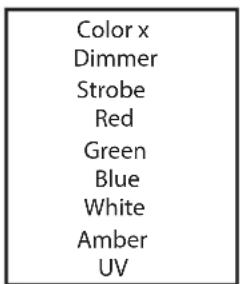
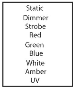
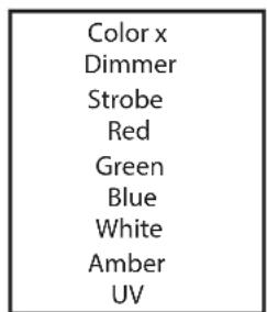
The standalone mode Static allows the Dimmer, Strobe, R, G, B, W, A and UV values to be set directly on the device with values between 000 and 255, in a similar way to with a DMX controller. In this way, an individual scene can be created without an additional DMX controller. Starting from main display 1, press MENU to enter the main menu. Now use the controls UP and DOWN to select the menu item Stand
Alone and confirm with ENTER. Again use UP and DOWN to select the standalone mode Static and confirm with ENTER. Use UP and DOWN to select the menu item you wish to edit and confirm with ENTER. You can now use UP and DOWN to configure the desired setting from 000 to 255. Confirm all entries with ENTER. The strobe effect values correspond to those in channel 2 of the DMX table 4CH and channel 3 of tables 13CH1 and 20CH.
| Static |
| Dimmer |
| Strobe |
| Red |
| Green |
| Blue |
| White |
| Amber |
| UV |
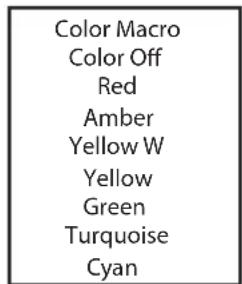
STANDALONE MODE COLOR MACRO
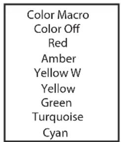
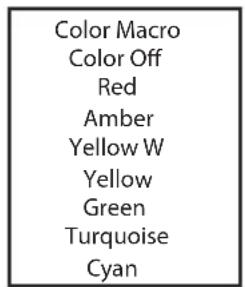
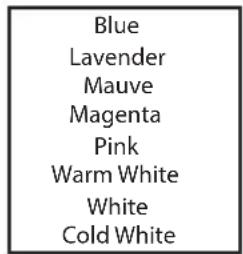
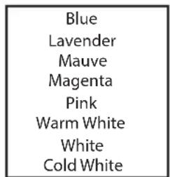
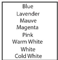
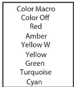
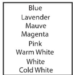
15 different color macros are available as presets. The brightness can be separately set for each preset.
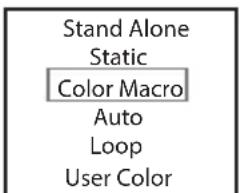
Starting from main display 1, press MENU to enter the main menu. Now use the controls UP and DOWN to select the menu item Stand
Alone and confirm with ENTER. Again use UP and DOWN to select the standalone mode Color Macro and confirm with ENTER. Using the UP and DOWN controls, select the desired color preset and confirm with ENTER (Color Off = blackout). You can now set the desired brightness from 000 to 100 using UP and DOWN; confirm with ENTER.
| Color Macro |
| Color Off |
| Red |
| Amber |
| Yellow W |
| Yellow |
| Green |
| Turquoise |
| Cyan |
| Blue |
| Lavender |
| Mauve |
| Magenta |
| Pink |
| Warm White |
| White |
| Cold White |
STANDALONE MODE AUTO
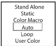
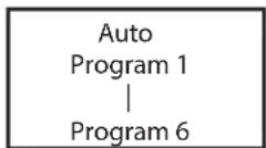
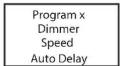
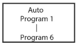
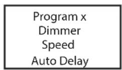
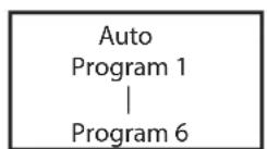
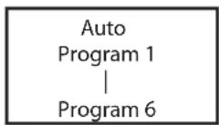
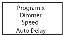
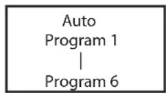
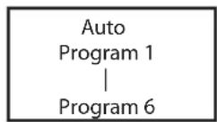
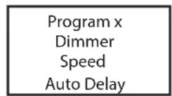
The 6 available auto programmes each consist of pre-programmed color change sequences, brightness (Dimmer), running speed (Speed) and the delay time for slave groups (Delay) can be configured separately for each programme.
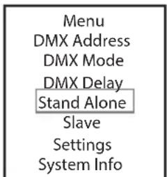
Starting from main display 1, press MENU to enter the main menu. Now use the controls UP and DOWN to select the menu item Stand
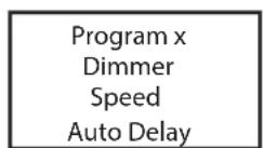
Alone and confirm with ENTER. Again use UP and DOWN to select the standalone mode Auto and confirm with ENTER. Now use the UP and DOWN to select the desired programme (programme 1 to 6) and confirm with ENTER. Now use UP and Down to select Dimmer, Speed or
Auto Delay, confirm with ENTER and adjust brightness or running speed from 000 to 100 as desired. The delay time can be set from 0 to 2 seconds in 0.1 second steps. Confirm all entries with ENTER.
STANDALONE MODE LOOP
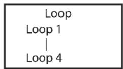
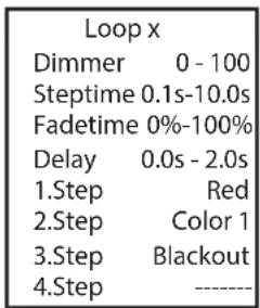
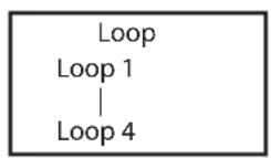
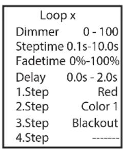
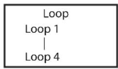
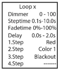
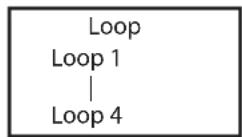
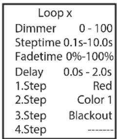
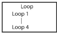
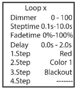
The standalone mode Loop allows you to individually configure, store and access up to four different color changing programmes. Brightness, step time, fade time and delay (signal delay) are also separately configurable. Starting from the main display, press MODE to enter the main menu. Using UP and DOWN, select the menu item Standalone and confirm with ENTER. Using the UP and DOWN buttons, select the stand-alone mode Loop and confirm with ENTER. Now use UP and DOWN to select the desired loop (Loop 1 – Loop 4) and confirm with ENTER.
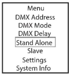
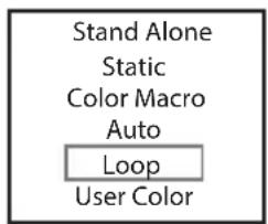
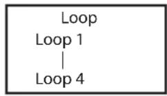
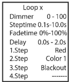
This will take you to the submenu for setting the submenu items (see table, select with UP and DOWN, confirm with ENTER, change value or status with UP and DOWN, confirm with ENTER). The settings for each loop are made separately and are retained even after restarting the device.
| STANDALONE MODE LOOP (Loop 1 – Loop 4) | ||
| Dimmer Sets brightness | less 0–100 | |
| Step time Sets step time | 0.1 s to 10.0 s | |
| Fade time Sets fade | time in percent 0% to 100% | |
| Delay Delay time for | slave groups 0.0 s to 2.0 s | |
| Step 1 15 colors from | Color Macro Red to CW (Cold White) | |
| 4 colors from User Color Color 1 to Color 4 | ||
| UV light UV | ||
| Blackout Blackout | ||
| Step 2 „ „ | ||
| Step 3 15 colors from | Color Preset Red to CW (Cold White) | |
| 4 colors from User Color Color 1 to Color 4 | ||
| UV light UV | ||
| Blackout Blackout | ||
| ---- | Skip step | |
| Step 4 „ „ | ||
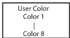
STANDALONE MODE USER COLOR
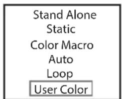
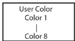
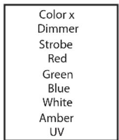
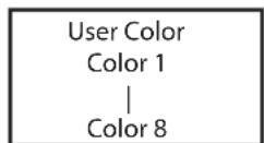
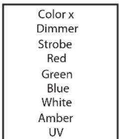
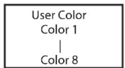
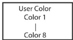
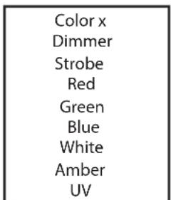
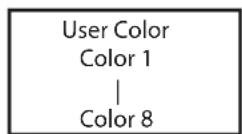
The standalone mode User Color allows you to store eight individual color presets for overall brightness, stroboscope (strobe) and a color mix of R, G, B, W, A and UV directly in the device.
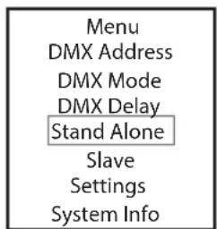
Starting from main display 1, press MENU to enter the main menu. Now use the controls UP and DOWN to select the menu item Stand Alone and confirm with ENTER. Again use UP and DOWN to select the standalone mode User Color and confirm with ENTER. Using UP and DOWN, now select the desired preset (color 1 to 8) and confirm with ENTER. Use UP and DOWN to select the menu item you wish to edit and confirm with ENTER. You can now use UP and DOWN to configure the desired setting from 000 to 255. The strobe effect values correspond to those in channel 2 of the DMX table 4CH and channel 3 of tables 13CH1 and 20CH. Confirm all entries with ENTER.
SLAVE MODE
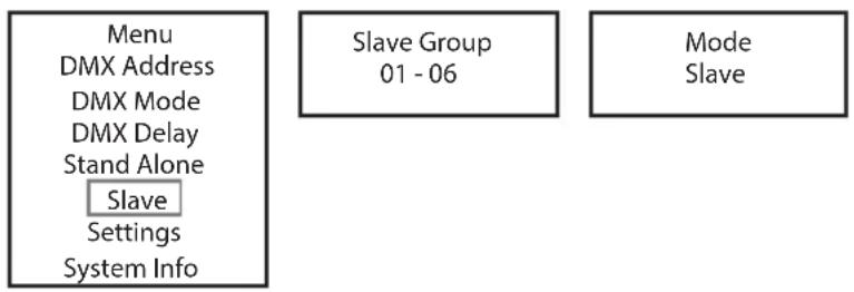
Standard slave mode: Starting from the main display, press MENU to enter the main menu. Using UP and DOWN, select the menu item Slave, confirm with ENTER, then select Slave Group 0 (Slave Group 00) and confirm again with ENTER. Connect the slave and the master unit (same model, same software version) with a DMX cable and enable one of the standalone modes on the master unit (Static, Color Macro, Auto, Loop, User Color). The slave unit will now follow the master unit.
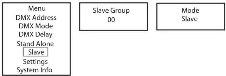
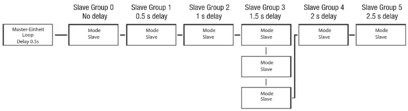
Advanced slave mode: If you wish to control the slave units in master/slave mode using one of the standalone modes Auto or Loop, the control signal can be reproduced with a time delay of up to 6 steps. The delay is set in the submenu item Delay in the relevant standalone mode, the delay factor is set in the slave menu of the corresponding spotlight. This is a simple way to create a running light effect with a large number of spotlights that are all the same model and have the same software version. This is otherwise only possible using a suitable DMX controller and time-consuming programming.
flowchart
graph TD
    A["Menu\nDMX Address\nDMX Mode\nDMX Delay\nStand Alone\nSlave\nSettings\nSystem Info"] --> B["Slave Group\n01 - 06"]
    B --> C["Mode\nSlave"]
Assign the spotlights to one of up to six groups according to preference, whereby several spotlights can be assigned to one group. The group number is also the factor by which the delay time set in the master unit is multiplied (see setup example).
flowchart
graph LR
    A["Master-Einheit Loop Delay 0.5s"] --> B["Slave Group 0 No delay"]
    B --> C["Mode Slave"]
    C --> D["Slave Group 1 0.5 s delay"]
    D --> E["Mode Slave"]
    E --> F["Slave Group 2 1 s delay"]
    F --> G["Mode Slave"]
    G --> H["Slave Group 3 1.5 s delay"]
    H --> I["Mode Slave"]
    I --> J["Mode Slave"]
    J --> K["Mode Slave"]
    K --> L["Slave Group 4 2 s delay"]
    L --> M["Mode Slave"]
    M --> N["Slave Group 5 2.5 s delay"]
    K --> O["Mode Slave"]
SYSTEM SETTINGS (Settings)
Starting from main display 1, press MENU to enter the main menu. Using UP and DOWN, select the menu item Settings and confirm with ENTER.
| Menu |
| DMX Address |
| DMX Mode |
| DMX Delay |
| Stand Alone |
| Slave |
| Settings |
| System Info |
This will take you to the submenu for setting the submenu items (see table, select with UP and DOWN, confirm with ENTER, change value or status with UP and DOWN, confirm with ENTER).
| Settings | ||||
| Wireless Settings | = W | -DMX settings W-DMX On/Off | On = W-DMX enabled | |
| Off = W-DMX disabled | ||||
| Reset Press ENTER | = Reset pairing with a transmitter and ready for new pairing | |||
| Display Reverse = | Rotate display On Display is rotated | through 180° (e.g. for overhead installation) | ||
| Off No display rotation | ||||
| Display = Display lighting On Permanently on | ||||
| Off Deactivation after approximately 1 minute of inactivity | ||||
| DMX Fail = Operating status with DMX signal fault | Hold Last command is retained | |||
| Blackout Activates blackout | ||||
| White All the LEDs have 100% output | ||||
| Dimmer Curve = Dimmer curve Linear Light intensity increases linearly with DMX value | ||||
| Exponential | Light intensity can be finely adjusted at lower DMX values and broadly adjusted at higher DMX values | |||
| Logarithmic | Light intensity can be broadly adjusted at lower DMX values and finely adjusted at higher DMX values | |||
| S-Curve | Light intensity can be finely adjusted at lower and higher DMX values and broadly adjusted at medium DMX values | |||
| DimResp. | = | Dimmer response | LED | Lamp responds abruptly to changes in DMX value |
| Halogen | Spotlight behaves like a halogen spotlight with soft brightness changes | |||
| LED Calibration | = Color calibration | Red, Green, Blue, White, Amber, UV | Individual color calibration. Cross-mode brightness setting of the 6 LED groups RGBWA+UV with values from 000–255 | |
| Auto Lock | = Automatic locking of the controls | On Automatic locking of the controls after approximately 1 minute of inactivity. Display shows: “LOCKED” To unlock: press and hold UP and DOWN simultaneously for approx. 5 seconds | ||
| Off Automatic locking of the controls is disabled | ||||
| IR Remote | = Activate or deactivate control by IR remote control | On IR remote control activated | ||
| Off IR remote control deactivated | ||||
| Factory Reset | = Reset to factory settings | Reset Now? | Resetting to factory settings: Perform reset with ENTER, cancel with MENU | |
SYSTEM INFORMATION (System Info)
Starting from main display 1, press MENU to enter the main menu. Using UP and DOWN, select the menu item System Info and confirm with ENTER.
| Menu |
| DMX Address |
| DMX Mode |
| DMX Delay |
| Stand Alone |
| Slave |
| Settings |
| System Info |
This will take you to the submenu for accessing the system information (see table, selection with UP and DOWN, confirm with ENTER, change status with UP and DOWN, confirm with ENTER).
| System Info | ||||
| Firmware = Displays device firmware Firmware | V1.xx | |||
| Temperature = Displays temperature of LED unit | LED xxx°C / xxx°F | |||
| C/F Unit Celsius (=display in degrees Celsius) | ||||
| Operation Hours = Displays operating time Total | xxxx:xxh | Displays total operating time in hours and minutes | ||
MANUAL LOCKING FUNCTION
In addition to the ability to automatically protect the lamp from accidental and unauthorised operation (see "Settings" – "Auto Lock"), the controls can also be locked manually. Press and hold the UP and DOWN controls simultaneously for approximately 5 seconds. "LOCKED" is now displayed and it is no longer possible to change the spotlight's settings via the controls. After approx. eight minutes, the current operating mode is displayed again. To unlock, press and hold the UP and DOWN controls simultaneously for approximately 5 seconds. The display will show the previously displayed information.
IR REMOTE CONTROL (optional)
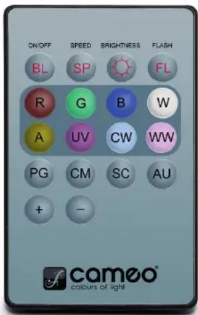
Activate the infrared remote control in the system settings (Settings) under "IR Remote" (IR Remote On). Aim the infrared remote control directly at the infrared sensor built into the front of the spotlight. The maximum range is approximately 8 metres. Deactivate control via the infrared remote control (IR Remote Off) when you wish to control the spotlight via DMX cable and W-DMX.
BL (ON/OFF / Blackout)
Press the BL button to switch off all LEDs (blackout), regardless of the operating mode enabled via remote control. Press the BL button again to reactivate the previously selected mode.
SP (Speed)
Speed setting for the color change programme in Auto Program (PG) operating mode. Select a color change program, press the SP button and then use the + and - buttons to set the desired speed from 000 to 100.
(Brightness)
Pressing the button for setting brightness immediately activates the Static operating mode. The overall brightness can now be set using the + and - buttons (set value is show in display).
FL (Flash/Stroboscope)
Pressing the button for setting the strobe immediately activates the Static operating mode. The strobe effect can now be set using the + and - buttons. The values for the stroboscope effect correspond to the values in channel 2 of the DMX table 4CH and channel 3 of the tables 13CH1 and 20CH (the set value is shown in the display).
R, G, B, W, A and UV (CW and WW without function)
Individual color mixtures can be created with the 6 buttons R, G, B, W, A and UV (static mode – static). Press the button for the desired LED color and use the + and - buttons to set the brightness from 000 to 255 (the value is shown in the display).
Example: Set red and blue at maximum brightness, and green, white, amber and UV at minimum (i.e. off) to achieve a bright magenta color blend.
PG (color change programme)
Select the desired color change programme 1–6 by repeatedly pressing PG and then set the brightness using the + and - buttons. Press the SP (Speed) button and then use the + and - buttons to set the programme speed (the programme, brightness and running speed are shown in the display).
CM (color presets)
Select the desired color preset by repeatedly pressing the CM button and then set the brightness using the + and - buttons (the color preset and brightness are shown in the display).
SC (no function)
AU (no function)
DIFFUSERS
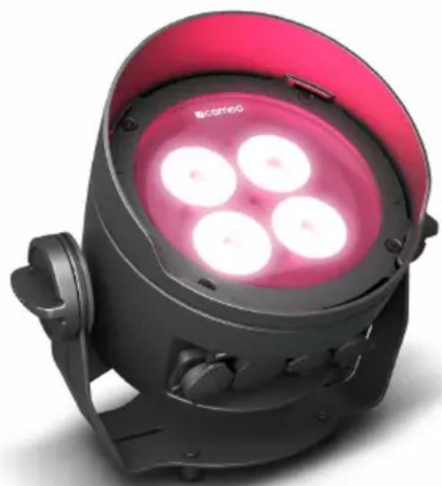
Two diffusers are supplied with the spotlight, each with a different beam angle (32°, 45°). The beam angle of the spotlight can be set at 22° (without diffuser), 32°, or 45°. Place the desired diffuser in front of the light-emitting lenses and turn it anticlockwise according to the principle of a bayonet connection until the four outer lugs on the edge of the diffuser engage in their holders in the anti-glare ring. The four magnets in the diffuser and the four opposing magnets set into the lens hood are now directly over each other and the diffuser is securely held in place. Ensure that the side of the diffuser with the magnets set into it is facing the spotlight and that the recess in the edge of the diffuser is in the flat area of the lens hood.
natural_image
Black and pink photo of a circular light fixture with three glowing bulbs, no visible text or symbols.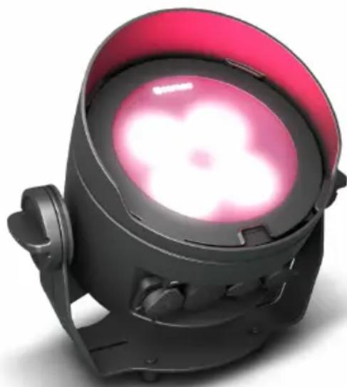
natural_image
Black industrial lamp with pink ambient lighting (no text or symbols visible)SET-UP AND INSTALLATION
Thanks to the wide stand and mounting bracket, the spotlight can be positioned in a suitable location on a level surface. Installation on a truss is possible with a suitable truss clamp, which is attached to the mounting bracket A. Suitable truss clamps are optionally available. Ensure firm connections and secure the spotlight by attaching a suitable safety cable to the securing lug on the mounting bracket. When installing on a truss, make sure that the mounting bracket is securely attached to the spotlight housing using the four fixing screws B.

Important safety notice: Overhead mounting, especially above persons, requires extensive experience, including the calculation of the load limit values of the installation material and regular safety inspection of all installation materials and spotlights. If you do not have these qualifications, do not attempt to perform an installation yourself. Refer instead to a qualified professional.
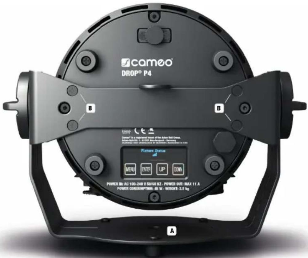
In order effectively use the tilt screw for uplight applications and for a more discreet appearance, the mounting bracket must be removed by loosening the four fixing screws B holding the mounting bracket to the spotlight housing with a suitable tool.
natural_image
Exterior view of a black cylindrical mechanical component with mounting feet (no text or symbols visible)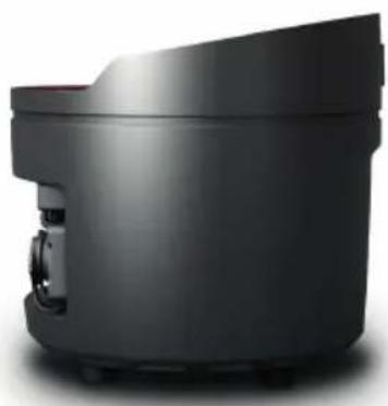
natural_image
Exterior view of a modern black cylindrical device with a small mechanical component visible (no text or symbols)DMX TECHNOLOGY
DMX-512
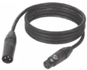
DMX (Digital Multiplex) is the designation for a universal transmission protocol for communications between corresponding devices and controllers. A DMX controller sends DMX data to the connected DMX device(s). The DMX data is always transmitted as a serial data stream that is forwarded from one connected device to the next via the "DMX IN" and "DMX OUT" connectors (XLR plug-type connectors) that are found on every DMX-capable device, provided the maximum number of devices does not exceed 32 units. The last device in the chain needs to be equipped with a terminator (terminating resistor).
natural_image
Coiled black cable with two connectors and a 3-pin connector (no text or symbols visible)DMX CONNECTION
DMX is the common "language" via which a very wide range of types and models of equipment from various manufacturers can be connected with one another and controlled via a central controller, provided that all of the devices and the controller are DMX compatible. For optimum data transmission, it is necessary to keep the connecting cables between the individual devices as short as possible. The order in which the devices are integrated in the DMX network has no influence on the addresses. Thus the device with the DMX address 1 can be located at any position in the (serial) DMX chain: at the beginning, at the end or somewhere in the middle. If the DMX address 1 is assigned to a device, the controller "knows" that it should send all data allocated to address 1 to this device regardless of its position in the DMX network.
SERIAL CONNECTION OF MULTIPLE LIGHTS
- Connect the male XLR connector (3-pin or 5-pin) of the DMX cable to the DMX output (female XLR socket) of the first DMX device (e.g. DMX-Controller).
- Connect the female 3-pin XLR connector of the DMX cable connected to the first projector to the DMX input (male 3-pin socket) of the next DMX device. In the same way, connect the DMX output of this device to the DMX input of the next device and repeat until all devices have been connected. Please note that as a rule, DMX devices are connected in series and connections cannot be shared without active splitters. The maximum number of DMX devices in a DMX chain should not exceed 32 units.
The Adam Hall 3 STAR, 4 STAR, and 5 STAR product ranges include an extensive selection of suitable cables.
DMX CABLES
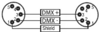
When fabricating your own cables, always observe the illustrations on this page. Never connect the shielding of the cable to the ground contact of the plug, and always make certain that the shielding does not come into contact with the housing of the XLR plug. If the shielding is connected to the ground, this can lead to short-circuiting and system malfunctions.
PIN ASSIGNMENT
DMX cable with 3-pin XLR connectors: DMX cable with 5-pin XLR connectors (pin 4 and 5 are not used):

flowchart
graph LR
    A["1"] --> B["Shield"]
    C["3"] --> B
    D["2"] --> B
    B --> E["1"]
    B --> F["3"]
    B --> G["2"]
DMX TERMINATORS (TERMINATING RESISTORS)
To prevent system errors, the last device in a DMX chain needs to be equipped with a terminating resistor (120 ohm, 1/4 Watt).
3-pin XLR connector with a terminating resistor: K3DMXT3
5-pin XLR connector with a terminating resistor: K3DMXT5
PIN ASSIGNMENT
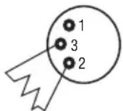
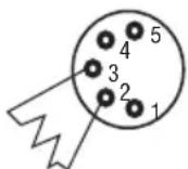
3-pin XLR connector: 5-pin XLR connector:
DMX ADAPTER
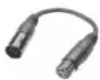
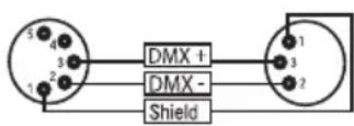
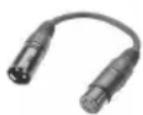
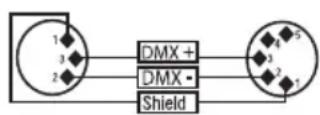
The combination of DMX devices with 3-pin connectors and DMX devices with 5-pin connectors in a DMX chain is possible with suitable adapters.
PIN ASSIGNMENT
DMX Adapter 5-pin XLR male to 3-pin XLR female: K3DGF0020
Pins 4 and 5 are not used.
PIN ASSIGNMENT
DMX Adapter 3-pin XLR male to 5-pin XLR female: K3DHM0020
Pins 4 and 5 are not used.
TECHNICAL DATA
Product number: CLDROPP4
| Product type: LED wash light | |
| Type: Outdoor spotlight | |
| Color spectrum LED: RGBWA+UV | |
| Number of LEDs: 4 | |
| LED type: 15 W | |
| PWM frequency: 800 Hz | |
| Beam angle: Beam Angle 22° / Field Angle 38° | |
| 1. Filter Medium BA 32° | |
| 2. Filter Wide BA 45° | |
| DMX input: 3-pin | |
| DMX output: 3-pin | |
| DMX mode: 20-channel / 13-channel 2/ 13-channel 1 / 7-channel / 6-channel / 4-channel / 3-channel | |
| DMX functions: Dimmer, Dimmer Fine, RGBWA+UV, RGBWA+UV Fine, Stroboscope, Color Macros, Color Change, Color Blending, System Settings | |
| Standalone functions: | Color Mixing, Color Macros, Auto Programmes, Loop Function, User Color, Master/Slave Mode |
| Control: | DMX, W-DMX, RDM |
| Operating controls: | Menu, Enter, Up, Down |
| Display elements: | OLED display |
| Operating voltage: | 100–240 V AC / 50–60 Hz |
| Power consumption: 45 W | |
| Light intensity (@ 1 m/3 m): | 6750 lx / 755 lx |
| Luminous flux: | 1100 lm |
| CRI: | White LED > 79 |
| Power supply connection: | TRUE1 compatible input (output max 11 A) |
| Ambient temperature (in operation): | 0 – 40 °C |
| Protection class: | IP65 |
| Power supply certificate: | CE, RoHS, ETL, FCC |
| Housing material: | Metal |
| Housing color: | Black |
| Housing cooling: | Convection cooling |
| Dimensions (W x H x D, without bracket): | 186 mm x 170 mm x 170 mm |
| Weight: | 2.8 kg |
| Additional features: | 1x True1 compatible power cable, 2x filters and 1x mounting bracket included |
MANUFACTURER'S DECLARATIONS
MANUFACTURER'S WARRANTY & LIMITATIONS OF LIABILITY
You can find our current warranty conditions and limitations of liability at: https://cdn-shop.adamhall.com/media/pdf/MANUFACTURERS-DECLARATIONS_CAMEO.pdf. To request warranty service for a product, please contact Adam Hall GmbH, Adam-Hall-Str. 1, 61267 Neu Anspach / Email: Info@adamhall.com / +49 (0)6081 / 9419-0.

CORRECT DISPOSAL OF THIS PRODUCT
(valid in the European Union and other European countries with a differentiated waste collection system)
This symbol on the product, or on its documents indicates that the device may not be treated as household waste. This is to avoid environmental damage or personal injury due to uncontrolled waste disposal. Please dispose of this product separately from other waste and have it recycled to promote sustainable economic activity. Household users should contact either the retailer where they purchased this product, or their local government office, for details on where and how they can recycle this item in an environmentally friendly manner. Business users should contact their supplier and check the terms and conditions of the purchase contract. This product should not be mixed with other commercial waste for disposal.
FCC STATEMENT
This device complies with Part 15 of the FCC Rules. Operation is subject to the following two conditions:
(1) This device may not cause harmful interference, and
(2) This device must accept any interference received, including interference that may cause undesired operation
CE COMPLIANCE
Adam Hall GmbH states that this product meets the following guidelines (where applicable):
R&TTE (1999/5/EC) or RED (2014/53/EU) from June 2017
Low voltage directive (2014/35/EU)
EMV directive (2014/30/EU)
RoHS (2011/65/EU)
The complete declaration of conformity can be found at www.adamhall.com.
Furthermore, you may also direct your enquiry to info@adamhall.com.
DEUTSCH
flowchart
graph LR
    A["DMX Controller"] --> B["DMX Delay Group 0 by DMX? No Delay 0.0s"]
    B --> C["DMX Delay Group 1 by DMX? No Delay 1.5s"]
    C --> D["DMX Delay Group 2 by DMX? No Delay 1.5s"]
    D --> E["DMX Delay Group 3 by DMX? No Delay 1.5s"]
    E --> F["DMX Delay Group 4 by DMX? No Delay 1.5s"]
    F --> G["DMX Delay Group 5 by DMX? No Delay 1.5s"]
flowchart
graph LR
    A["DMX Controller\nDMX Delay 0.5s"] --> B["DMX Delay\nGroup 0\nby DMX? Yes"]
    B --> C["DMX Delay\nGroup 1\nby DMX? Yes"]
    C --> D["DMX Delay\nGroup 2\nby DMX? Yes"]
    D --> E["DMX Delay\nGroup 3\nby DMX? Yes"]
    E --> F["DMX Delay\nGroup 4\nby DMX? Yes"]
    F --> G["DMX Delay\nGroup 5\nby DMX? Yes"]
    style A fill:#f9f,stroke:#333
    style G fill:#f9f,stroke:#333
STAND-ALONE-BETRIEBSART STATIC
| Static |
| Dimmer |
| Strobe |
| Red |
| Green |
| Blue |
| White |
| Amber |
| UV |
STAND-ALONE-BETRIEBSART COLOR MACRO
| Blue |
| Lavender |
| Mauve |
| Magenta |
| Pink |
| Warm White |
| White |
| Cold White |
STAND-ALONE-BETRIEBSART AUTO
STAND-ALONE-BETRIEBSART LOOP
SLAVE-BETRIEB
FL (Flash / Stroboskop)
natural_image
Black and red photo of a circular light fixture with three glowing bulbs, no visible text or symbols.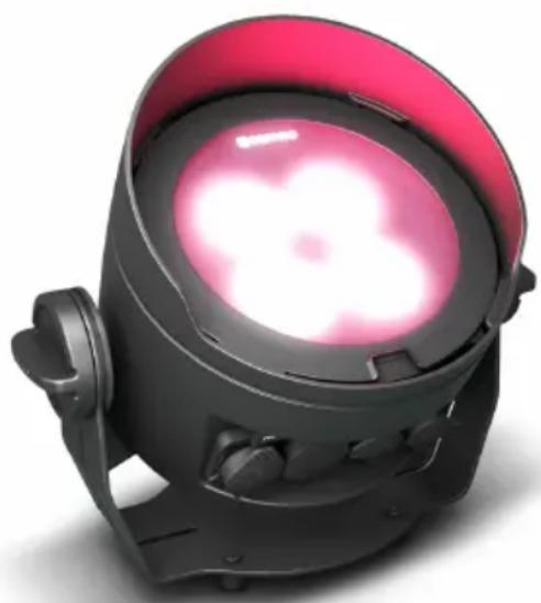
natural_image
Black and red industrial lamp with glowing pink light (no text or symbols visible)natural_image
Black cylindrical electronic device with mounting feet, shown in profile view (no text or symbols visible)
natural_image
Exterior view of a modern black cylindrical device with a small handle and mounting feet (no text or symbols visible)DMX TECHNIK
DMX-512
natural_image
Coiled black cable with two connectors and a connector pin (no text or symbols visible)DMX-VERBINDUNG:
DMX-Adapter 5-Pol XLR male auf 3-Pol XLR female: K3DGF0020
| Static |
| Dimmer |
| Strobe |
| Red |
| Green |
| Blue |
| White |
| Amber |
| UV |
MODE DE FONCTIONNEMENT STAND ALONE COLOR MACRO
MODE STAND ALONE AUTO
MODE DE FONCTIONNEMENT STAND ALONE LOOP
MODE SLAVE
FL (Flash/stroboscope)
natural_image
Black and red photo of a circular light fixture with three glowing bulbs, no visible text or symbols.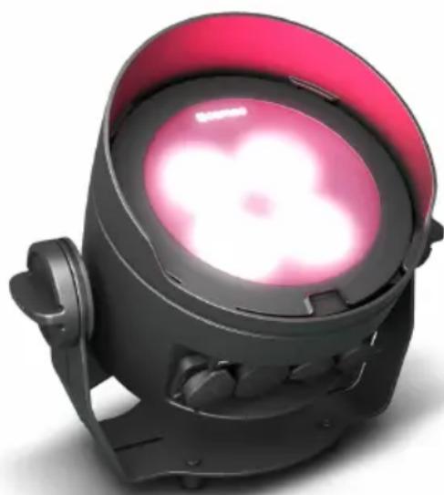
natural_image
Black and red industrial lamp with pink ambient lighting (no text or symbols visible)INSTALLATION ET MONTAGE
natural_image
Exterior view of a black cylindrical mechanical component with mounting feet (no text or symbols visible)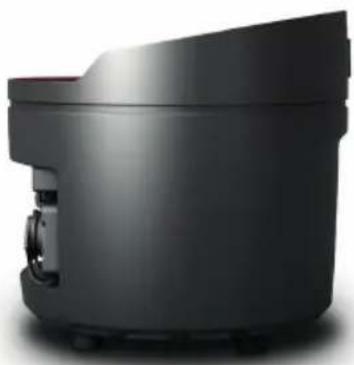
natural_image
Exterior view of a modern black cylindrical device with a small mechanical component on the side (no visible text or symbols)TECHNIQUE DMX
DMX-512
natural_image
Coiled black cable with two connectors and a three-pin connector (no text or symbols visible)PROTOCOLE DMX
(Valid in the European Union and other European countries with waste separation)
| Static |
| Dimmer |
| Strobe |
| Red |
| Green |
| Blue |
| White |
| Amber |
| UV |
MODO AUTÓNOMO COLOR MACRO
| Color Macro |
| Color Off |
| Red |
| Amber |
| Yellow W |
| Yellow |
| Green |
| Turquoise |
| Cyan |
MODO AUTÓNOMO AUTO
MODO AUTÓNOMO LOOP

MODO ESCLAVO
FL (flash / estrobo)
natural_image
Two black and red photoelectric light headsets with pink ambient lights (no text or symbols visible)natural_image
Black cylindrical electronic device with mounting feet, shown in profile view (no text or symbols visible)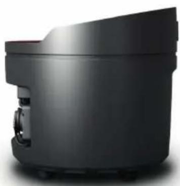
natural_image
Exterior view of a modern black cylindrical device with a small mechanical component on the side (no text or symbols visible)TECNOLOGÍA DMX
DMX512
natural_image
Coiled black cable with two connectors (no text or symbols visible)CONEXIONADO DMX
WIDOK GŁÓWNY 1: TRYB PRACY STANDALONE
WIDOK GŁÓWNY 2: STAN OPRAWY
STATUS W-DMX™ SIŁA SYGNAŁU RF
USTAWIANIE ADRESU STARTOWEGO DMX
TRYB PRACY STANDALONE COLOR MACRO
USTAWIANIE TRYBU PRACY STANDALONE AUTO

TRYB PRACY STANDALONE LOOP
TRYB SLAVE
FL (Flash / Stroboskop)
natural_image
Black and red photo of a spotlights with three glowing pink lights (no text or symbols visible)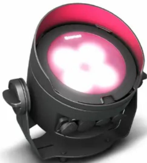
natural_image
Black industrial lamp with pink ambient lighting (no text or symbols visible)USTAWIANIE I MONTAŻ
natural_image
Black cylindrical electronic device with mounting feet, shown from front and side (no visible text or symbols)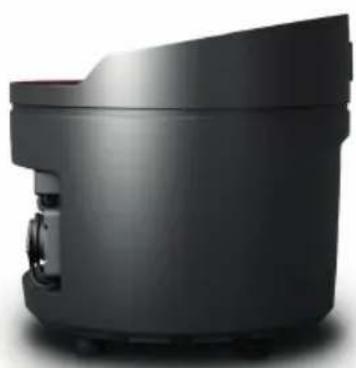
natural_image
Exterior view of a modern black cylindrical device with a small mechanical component attached (no visible text or symbols)TECHNIKA DMX
DMX-512
natural_image
Coiled black cable with two connectors (no text or symbols visible)ZŁĄCZE DMX:
SENSORE AD INFRAROSSI
MODALITÀ SLAVE
FL (Flash/stroboscopio)
natural_image
Two black and red photoelectric light headsets with glowing pink lights, no visible text or symbolsnatural_image
Black cylindrical mechanical component with mounting feet, shown in profile view (no text or symbols visible)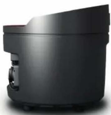
natural_image
Exterior view of a modern black cylindrical device with a small mechanical component attached (no visible text or symbols)TECNOLOGIA DMX
DMX512
natural_image
Coiled black cable with two connectors (no text or symbols visible)COLLEGAMENTO DMX:
EN: (1*) After the adjustments have been made, set the value to 000 to avoid disturbance by endless function call.

- DROP P4
- CONTENTS / INHALTSVERZEICHNIS / CONTENU / CONTENIDO / TREŚĆ / CONTENUTO
- ENGLISH
- DEUTSCH
- SAFETY INFORMATION
- FOR DEVICES CONNECTED TO A POWER SUPPLY:
- CAUTION:
- CAUTION! IMPORTANT INFORMATION ABOUT LIGHTING PRODUCTS!
- INTRODUCTION
- OUTDOOR UPLIGHT SPOTLIGHT WITH 4 X 15 W RGBWA+UV LEDS AND W-DMX™
- CONTROL FUNCTIONS
- FEATURES
- CONNECTIONS, OPERATING AND DISPLAY ELEMENTS
- POWER IN
- POWER OUT
- DMX IN
- DMX OUT
- OLED DISPLAY
- TOUCH-SENSITIVE CONTROLS
- TILT
- RUBBER FEET
- SECURING LUG
- GRIP SCREWS
- STAND OR MOUNTING BRACKET
- PRESSURE EQUALISATION ELEMENT
- INFRARED SENSOR
- OPERATION
- PLEASE NOTE
- MAIN DISPLAY 1 DMX OPERATING MODE
- MAIN DISPLAY 1 STANDALONE MODE
- MAIN DISPLAY SLAVE MODE
- MAIN DISPLAY 2 FIXTURE STATUS
- W-DMXTM
- CONFIGURE DMX START ADDRESS
- CONFIGURE DMX MODE
- DMX DELAY
- STANDALONE MODE STATIC
- STANDALONE MODE COLOR MACRO
- STANDALONE MODE AUTO
- STANDALONE MODE LOOP
- STANDALONE MODE USER COLOR
- SLAVE MODE
- SYSTEM SETTINGS (Settings)
- SYSTEM INFORMATION (System Info)
- MANUAL LOCKING FUNCTION
- IR REMOTE CONTROL (optional)
- BL (ON/OFF / Blackout)
- SP (Speed)
- (Brightness)
- FL (Flash/Stroboscope)
- R, G, B, W, A and UV (CW and WW without function)
- PG (color change programme)
- CM (color presets)
- DIFFUSERS
- SET-UP AND INSTALLATION
- DMX TECHNOLOGY
- DMX-512
- DMX CONNECTION
- SERIAL CONNECTION OF MULTIPLE LIGHTS
- DMX CABLES
- PIN ASSIGNMENT
- DMX TERMINATORS (TERMINATING RESISTORS)
- DMX ADAPTER
- TECHNICAL DATA
- MANUFACTURER'S DECLARATIONS
- MANUFACTURER'S WARRANTY & LIMITATIONS OF LIABILITY
- CORRECT DISPOSAL OF THIS PRODUCT
- FCC STATEMENT
- CE COMPLIANCE
- STAND-ALONE-BETRIEBSART STATIC
- STAND-ALONE-BETRIEBSART COLOR MACRO
- STAND-ALONE-BETRIEBSART AUTO
- STAND-ALONE-BETRIEBSART LOOP
- SLAVE-BETRIEB
- FL (Flash / Stroboskop)
- DMX TECHNIK
- DMX-VERBINDUNG:
- MODE DE FONCTIONNEMENT STAND ALONE COLOR MACRO
- MODE STAND ALONE AUTO
- MODE DE FONCTIONNEMENT STAND ALONE LOOP
- MODE SLAVE
- INSTALLATION ET MONTAGE
- TECHNIQUE DMX
- PROTOCOLE DMX
- MODO AUTÓNOMO COLOR MACRO
- MODO AUTÓNOMO AUTO
- MODO AUTÓNOMO LOOP
- MODO ESCLAVO
- FL (flash / estrobo)
- TECNOLOGÍA DMX
- DMX512
- CONEXIONADO DMX
- WIDOK GŁÓWNY 1: TRYB PRACY STANDALONE
- WIDOK GŁÓWNY 2: STAN OPRAWY
- USTAWIANIE ADRESU STARTOWEGO DMX
- TRYB PRACY STANDALONE COLOR MACRO
- USTAWIANIE TRYBU PRACY STANDALONE AUTO
- TRYB PRACY STANDALONE LOOP
- TRYB SLAVE
- USTAWIANIE I MONTAŻ
- TECHNIKA DMX
- ZŁĄCZE DMX:
- SENSORE AD INFRAROSSI
- MODALITÀ SLAVE
- FL (Flash/stroboscopio)
- TECNOLOGIA DMX
- COLLEGAMENTO DMX:
Brand : Cameo
Model : DROP P4
Category : Lighting