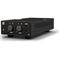
HPA 2 - Audio Amplifier LD Systems - Free user manual and instructions
Find the device manual for free HPA 2 LD Systems in PDF.


| Product type | 2-output headphone amplifier for fixed installation |
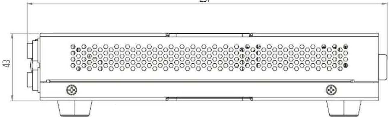
| Dimensions (W x H x D) | 106 x 53 x 225 mm |
| Weight | 0.850 kg |
| Power supply | External, 100-240 V ~ 50/60 Hz, output 24 V / 0.5 A |
| Max. power consumption | 5 W |
| Number of line inputs | 2 |
| Line input connectors | Euroblock 3.81 mm (balanced) or 6.35 mm TRS jack |
| Number of line outputs | 2 |
| Number of headphone outputs | 4 (2 front 3.5 mm mini-jack + 2 rear 6.35 mm jack) |
| Headphone output power (per channel) | 2 x 75 mW into 33 Ω |
| Minimum load impedance | 16 Ω |
| Frequency response | 18 Hz - 50 kHz (-0.5 dB) |
| Signal-to-noise ratio (headphone outputs) | > 100 dB |
| Distortion (THD+N) | < 0.03 % |
| Nominal input sensitivity | -9 dBu |
| Maximum gain | 12 dB |
| Cooling system | Convection (fanless) |
| Indicators | Power (white), Signal (white), Clipping (red) |
| Mode selectors | Stereo/Mono, HP/HP+MON |
| Chassis material | Steel, plastic front panel |
| Included accessories | Power supply unit, mounting plates, rubber feet, Euroblock connectors, manual |
| Operating temperature | 0 °C to 40 °C, < 85 % RH non-condensing |
| Safety class | Class III (extra low voltage) |
| Maintenance | Clean with damp cloth; do not use solvents; do not cover ventilation slots |
| Repairability | No user serviceable parts; intervention by qualified personnel |
Frequently Asked Questions - HPA 2 LD Systems
User questions about HPA 2 LD Systems
0 question about this device. Answer the ones you know or ask your own.
Ask a new question about this device
Download the instructions for your Audio Amplifier in PDF format for free! Find your manual HPA 2 - LD Systems and take your electronic device back in hand. On this page are published all the documents necessary for the use of your device. HPA 2 by LD Systems.
USER MANUAL HPA 2 LD Systems
SAFETY INSTRUCTIONS 5
NOTES FOR INDOOR INSTALLATION EQUIPMENT 7
PACKAGING CONTENT 8
INTRODUCTION 8
CONNECTIONS, OPERATING AND DISPLAY ELEMENTS 9
CONNECTION EXAMPLES 11
TERMINAL BLOCK CONNECTIONS 12
UNDER / ON-TABLE MOUNTING 12
CARE, MAINTENANCE AND REPAIR 13
DIMENSIONS 14
TECHNICAL DATA 14
DISPOSAL 16
MANUFACTURER'S DECLARATIONS 17
DEUTSCH
INFORMATIONEN ZU DIESER
This device was developed and manufactured under high quality requirements to ensure many years of trouble-free operation. This is what LD Systems stands for with its name and many years of experience as a manufacturer of high-quality audio products. Please read these operating instructions carefully so that you can quickly and optimally use your new LD Systems product.
You can find more information about LD Systems on our website WWW.LD-SYSTEMS.COM
ABOUT THIS MANUAL
- Read the safety instructions and the entire manual carefully before commissioning.
- Observe the warnings on the unit and in the operating instructions.
- Always keep the operating instructions within reach.
- If you sell or pass on the appliance, be sure to hand over these operating instructions as well, as they are an essential part of the product.
INTENDED USE
The product is a device for professional audio installation! The product has been developed for professional use in the field of audio installation and is not intended for use in households! Furthermore, this product is intended for installation by qualified persons with specialist knowledge and for operation by instructed persons! The use of the product outside the specified technical data and operating conditions is considered as not intended! Liability for damages and third party damages to persons and property due to non-intended use is excluded!
The product is not suitable for:
- Persons (including children) with limited physical, sensory or mental capabilities or lack of experience and knowledge.
- Children (children must be instructed not to play with the device).
EXPLANATIONS OF TERMS AND SYMBOLS
- DANGER: The word DANGER, possibly in combination with a symbol, indicates immediately dangerous situations or conditions for life and limb.
- WARNING: The word WARNING, possibly in combination with a symbol, indicates potentially dangerous situations or conditions for life and limb.
- CAUTION: The word CAUTION, possibly in combination with a symbol, is used to indicate situations or conditions that may lead to injury.
- ATTENTION: The word ATTENTION, possibly in combination with a symbol, refers to situations or states that can lead to damage to property and/or the environment.
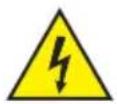
This symbol indicates hazards that can cause an electric shock.

This symbol indicates danger spots or dangerous situations.
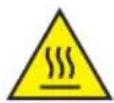
This symbol indicates danger from hot surfaces.
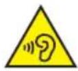
This symbol indicates danger from high volumes.

This symbol indicates supplementary information on the operation of the product.

This symbol denotes a device that does not contain any user-serviceable parts.
This symbol indicates electrical equipment designed primarily for indoor use.
SAFETY INSTRUCTIONS
DANGER:
- Do not open or modify the device.
- If your device is no longer working properly, liquids or objects have gotten inside the device, or the device has been damaged in any other way, switch it off immediately and disconnect it from the power supply. This device may only be repaired by authorized specialist personnel.
- For devices of protection class 1, the protective conductor must be connected correctly. Never interrupt the protective conductor. Protection class 2 devices do not have a protective conductor.
- Ensure that live cables are not kinked or otherwise mechanically damaged.
- Never bypass the device fuse.
WARNING:
- The device must not be put into operation if it shows obvious signs of damage.
- The device may only be installed in a voltage-free state.
- If the power cord of the device is damaged, the device must not be put into operation.
- Permanently connected power cords may only be replaced by a qualified person.
DANGER:
- Do not operate the device if it has been exposed to severe temperature fluctuations (e.g. after transport). Humidity and condensation could damage the device. Do not switch on the device until it has reached the ambient temperature.
- Make sure that the voltage and frequency of the mains supply correspond to the values indicated on the device. If the device has a voltage selector switch, do not connect the device until this is set correctly. Only use suitable power cords.
- To disconnect the device from the mains at all poles, it is not enough to press the on/off switch on the device.
- Ensure that the fuse used corresponds to the type printed on the device.
- Make sure that appropriate measures against overvoltage (e.g. lightning) have been taken.
- Note the specified maximum output current on devices with a power out connection. Make sure that the total power consumption of all connected devices does not exceed the specified value.
- Only replace pluggable power cords with original cables.

DANGER:
- Danger of suffocation! Plastic bags and small parts must be kept out of the reach of people (including children) with reduced physical, sensory or mental abilities.
- Danger from falling! Make sure the device is installed securely and cannot fall. Only use suitable tripods or attachments (especially for fixed installations). Make sure accessories are properly installed and secured. Make sure that the applicable safety regulations are observed.

WARNING:
- Only use the device in the manner intended.
- Only operate the device with the accessories recommended and intended by the manufacturer.
- During installation, observe the safety regulations applicable in your country.
- After connecting the unit, check all cable routes to avoid damage or accidents, e.g. due to tripping hazards.
- Be sure to observe the specified minimum distance to normally flammable materials! Unless this is explicitly stated, the minimum distance is 0.3 m.

ATTENTION:
- There is a risk of jamming with moving components such as mounting brackets or other moving components.
- In the case of units with motor-driven components, there is a risk of injury from the movement of the unit. Sudden device movement can cause shock reactions.

DANGER:
- Do not install or operate the device near radiators, heat registers, stoves or other heat sources. Make sure that the device is always installed in such a way that it is sufficiently cooled and cannot overheat.
- Do not place any sources of ignition such as burning candles near the device.
- Ventilation openings must not be covered and fans must not be blocked.
- Use the original packaging or packaging provided by the manufacturer for transport.
- Avoid shock or shock to the device.
- Observe the IP protection class and the environmental conditions such as temperature and humidity according to the specification.
- Devices can be continuously developed. In the event of deviating information on operating conditions, performance or other device properties between the operating instructions and the device labeling, the information on the device always has priority.
- The device is not suitable for tropical climate zones and for operation above 2000 m above sea level.

ATTENTION:
Connecting signal cables can result in significant noise interference. Make sure that devices connected to the output are muted during plugging. Otherwise, noise levels can cause damage.
ATTENTION HIGH VOLUMES WITH AUDIO PRODUCTS!
This device is intended for professional use.
The commercial operation of this device is subject to the applicable national regulations and guidelines for accident prevention.
Hearing damage due to high volumes and continuous exposure: The use of this product can generate high sound pressure levels (SPL) which can cause hearing damage. Avoid exposure to high volumes.

NOTES FOR INDOOR INSTALLATION EQUIPMENT
- Units for installation applications are designed for continuous operation.
- Units for indoor installation are not weatherproof.
- Surfaces and plastic parts of installation equipment can also age, e.g. due to UV radiation and temperature fluctuations. This does not usually lead to functional restrictions.
- with permanently installed units, the deposition of impurities, e.g. dust, is to be expected. Be sure to observe the care instructions.
- Unless explicitly stated otherwise on the unit, the units are intended for installation heights of less than 5 m.
PACKAGING CONTENT
Remove the product from the packaging and remove all packaging material.
Please check the completeness and integrity of the delivery and notify your distribution partner immediately after purchase if the delivery is not complete or if it is damaged.
Included in the product packaging are:
- 1x HPA2 headphone amplifier
- 1x power supply unit
- 1 set of terminal blocks
- 1 mounting set for on-table or under-table mounting
- 1 set of rubber feet (pre-assembled)
- User manual
INTRODUCTION
Part of the TICA ^® series, the HPA 2 is a two-channel headphone amplifier designed to make monitoring flexible and easy.
The two stereo line inputs have independent gain control. Connect using standard 14 " (6.35 mm) TRS jacks or terminal block connections.
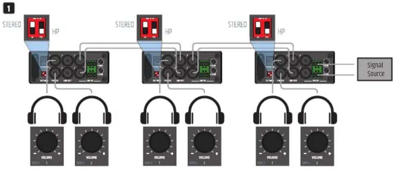
The HPA 2 comes with two headphone outputs and two line outputs using 14 " (6.35 mm) TRS jacks and two 3.5 mm headphone outputs connected in parallel to these. Daisy chain multiple units together for group listening environments. Input signal and clip LEDs help you keep everything in check.
The configuration switches let two people listen to the same stereo signal with independent volume control, or listen to independent mono signals per headphone channel, acting as two independent headphone amplifiers. Further options let you configure the volume knobs for individual headphone volume control or configure one knob for global headphone volume control and the other as a separate monitor output level control.
The HPA 2 works with high impedance headphones and very low impedances down to 16 Ohms. Its capacitor-free output stage means that the frequency response is not affected no matter what type of headphones you use – low or high impedance.
Its tiny (106 x 53 x 225 mm) form factor and included mounting plates allow it to be installed discreetly. Alternatively, it fits into 14 19 inch rack. Use the optional rack tray to slot up to four TICA ^ series products alongside each other and build a system to your exact requirements, using minimal rack space.
A great monitoring solution for audio professionals.
FEATURES
- Two channel headphone amplifier
- Two balanced line inputs with independent gain controls
- Two balanced line level outputs
• Signal and clip LEDs on each channel - Suitable for both low and high impedance headphones
- External 100 - 240V power supply
CONNECTIONS, OPERATING AND DISPLAY ELEMENTS
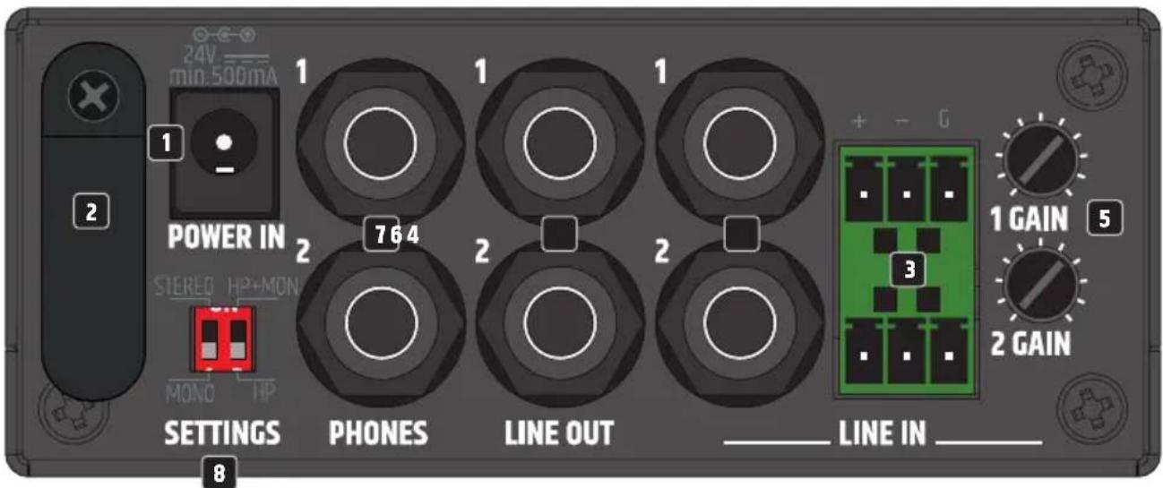
1 POWER IN
Low-voltage socket for supplying power to the device. To avoid damage to the device, please use only the original power supply (power supply unit included).
2 STRAIN RELIEF
Use the strain relief for the flexible cable of the power supply unit to protect the extra-low voltage socket, the extra-low voltage plug and the cable of the power supply unit from damage and to prevent the plug from being pulled out unintentionally.
3 LINE IN 1 + 2
Analogue audio inputs with balanced terminal block connections. The +, - and G poles are for the balanced input signal (suitable for unbalanced cabling). Terminal blocks are included in the packaging content. Only use the inputs with the terminal block connections and the jack sockets alternatively.
4 LINE IN 1 + 2
Analogue audio inputs with balanced 6.3 mm jack sockets. Only use the inputs with the terminal block connections and the jack sockets alternatively.
5 GAIN 1 + 2
Potentiometer for the input sensitivity of the line inputs LINE IN 1 and 2.
6 LINE OUT 1 + 2
Analogue audio outputs with balanced 6.3 mm jack sockets.
7 HEADPHONES 1 + 2
Headphone outputs with 6.3 mm stereo jack sockets. The 6.3 mm sockets on the rear are wired in parallel with the 3.5 mm sockets on the front and can be used together if necessary. Make sure that the total impedance of the headphones used in parallel does not fall below 16 ohms.
8 SETTINGS
Switch 1 STEREO / MONO
STEREO: A stereo signal present at LINE IN is routed in stereo to the headphone outputs on the rear and front panel and at the line output LINE OUT 1 / 2.
MONO: LINE IN 1 is routed to headphone output 1 on the rear and front panel, and to LINE OUT 1. LINE IN 2 is routed to headphone output 2 on the rear and front panel, and to LINE OUT 2.
Switch 2 HP+MON / HP
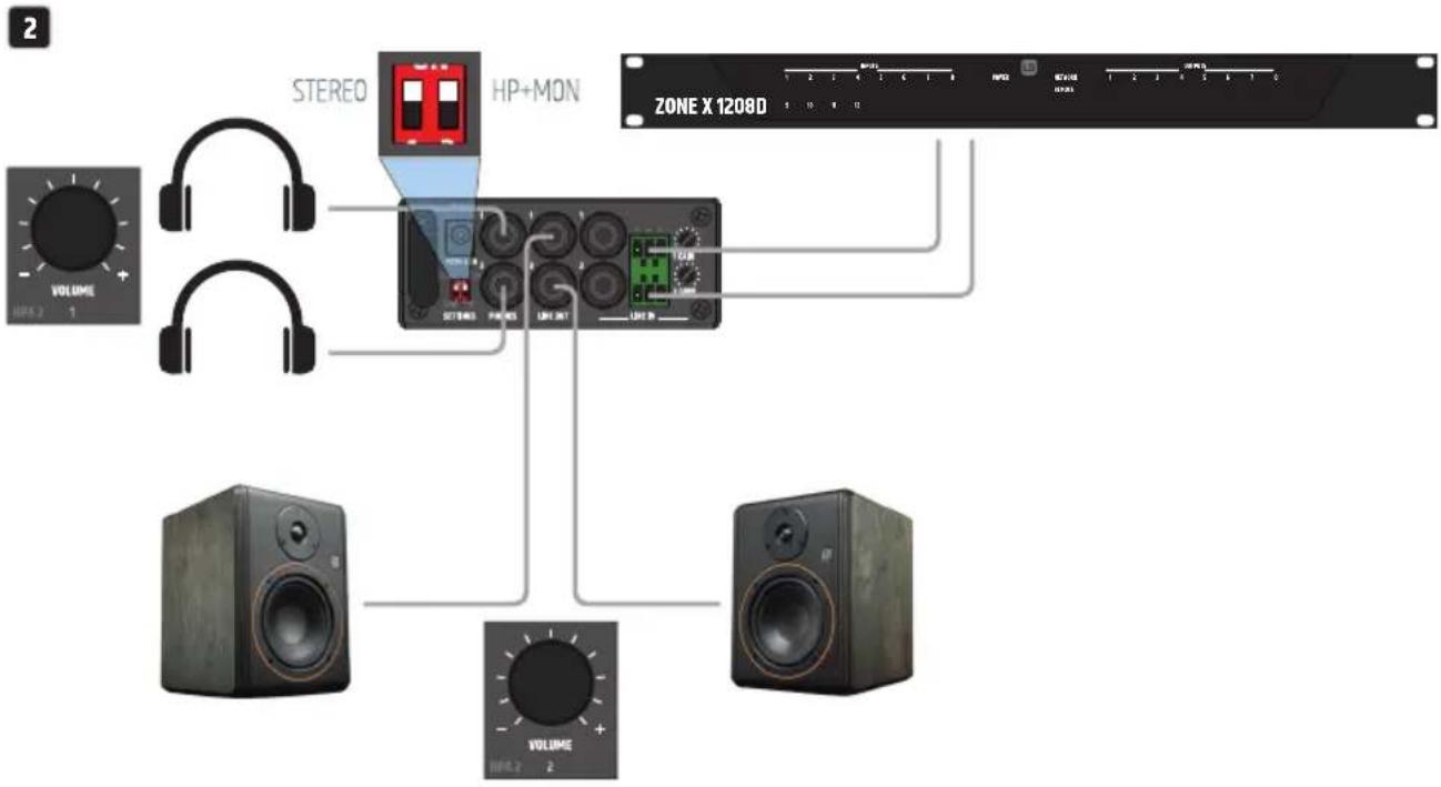
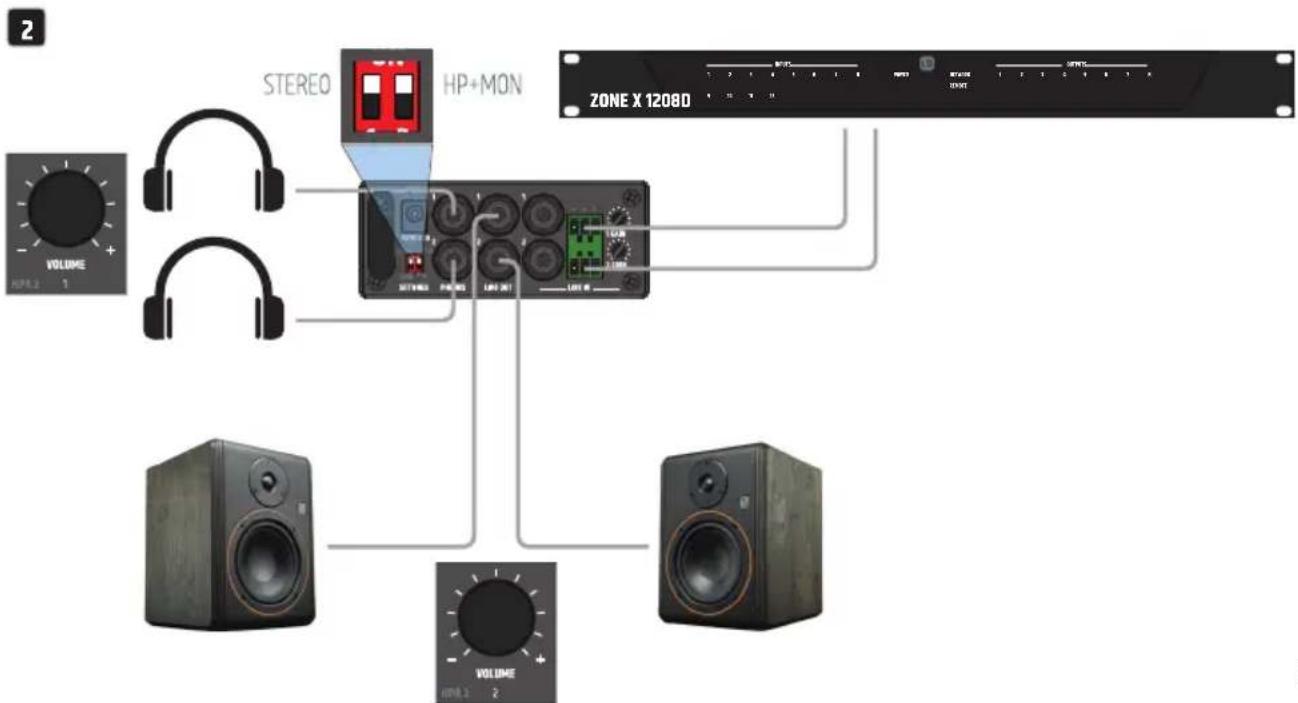
HP+MON: A signal applied to LINE IN is routed to the headphone outputs on the rear and front panel and to LINE OUT (e.g. for driving active studio monitors). The volume of PHONES 1 and 2 is adjusted with VOLUME 1 on the front panel, the volume of LINE OUT 1 / 2 with VOLUME 2.
HP: A signal applied to LINE IN is routed to the headphone outputs on the rear and front and to LINE OUT 1 / 2. The volume of PHONES 1 is adjusted with VOLUME 1 on the front panel, the volume of PHONES 2 with VOLUME 2. The Line output level is not affected by any volume control.
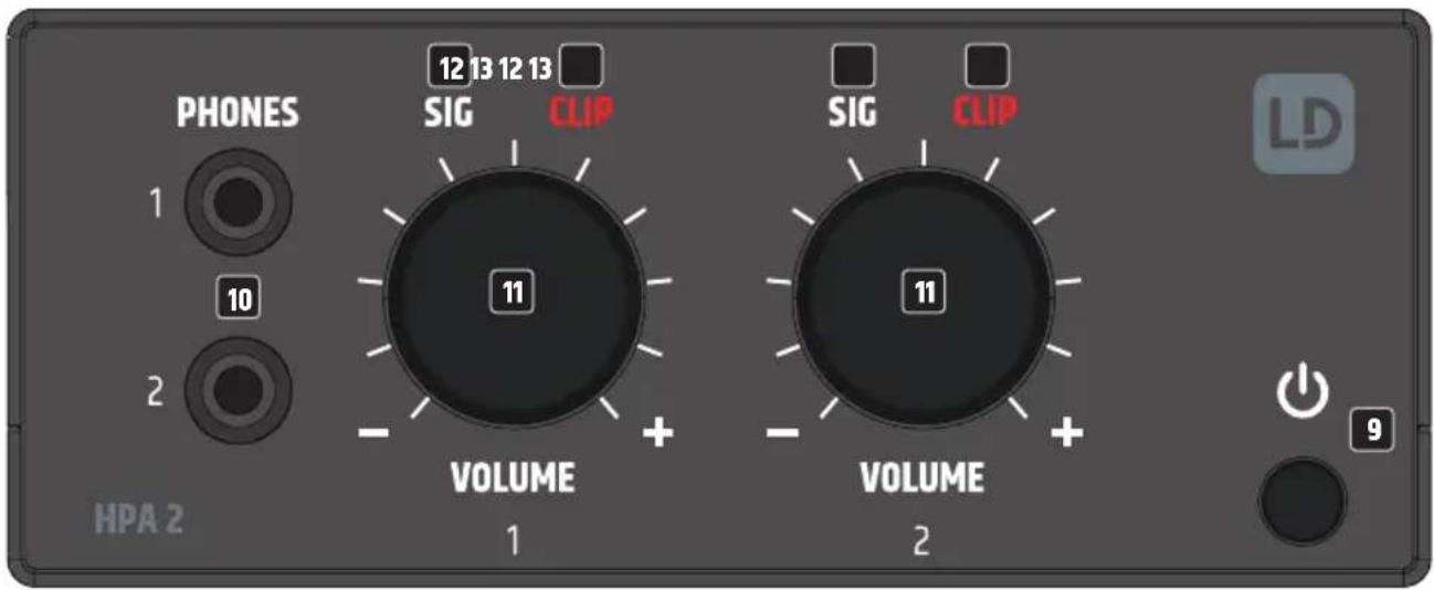
9 ON / OFF SWITCH AND POWER SYMBOL
Press the push button to switch the device on and again to switch it off. As soon as the HPA2 is correctly connected to the power supply and switched on, the power symbol lights up white.
10 HEADPHONES 1 + 2
Headphone outputs with 3.5 mm stereo jack sockets. The 6.3 mm sockets on the rear are wired in parallel with the 3.5 mm sockets on the front and can be used together if necessary. Make sure that the total impedance of the headphones used in parallel does not fall below 16 ohms.
11 VOLUME 1 + 2
Depending on the setting of the Settings switch on the back, the level controls have different functions.
SETTINGS - HP: One level control each for headphone outputs 1 and 2.
SETTINGS - HP+MON: VOLUME 1 controls the volume of the headphone outputs PHONES 1 and 2. VOLUME 2 controls the volume of the LINE OUT output.
Turning to the right increases the volume, turning to the left decreases it.
To avoid hearing damage, set the volume to minimum before using headphones or in-earphones and loudspeakers. Afterwards, increase the volume slowly.
Caution, high volume can damage hearing permanently.
12 SIG 1 + 2 (SIGNAL)
As soon as an audio signal is present at the headphone outputs or the LINE OUT output, the corresponding signal indicator lights up white.
13 CLIP 1 + 2
The red CLIP indicator lights up when the corresponding output is overdriven. If this occurs, reduce the volume level. Failure to do so may result in distorted sound reproduction and damage to the amplifier and the headphones or loudspeakers.
AIR VENTS
To prevent damage to the device, do not cover the ventilation openings on the left and right sides and on the top and bottom of the device and ensure that air can circulate freely. Covering the ventilation openings on the top or bottom of the enclosure when mounting it underneath or on top of a table is not critical, as the cooling provided by the ventilation openings on the remaining sides is sufficient.
CONNECTION EXAMPLES
flowchart
graph TD
    A["STEREO"] --> B["HP"]
    C["STEREO"] --> D["HP"]
    E["STEREO"] --> F["HP"]
    G["STEREO"] --> H["HP"]
    I["Signal Source"] --> J["VOLUME 1"]
    I --> K["VOLUME 2"]
    L["VOLUME 1"] --> M["VOLUME 2"]
    N["VOLUME 2"] --> O["VOLUME 2"]
    P["VOLUME 1"] --> Q["VOLUME 2"]
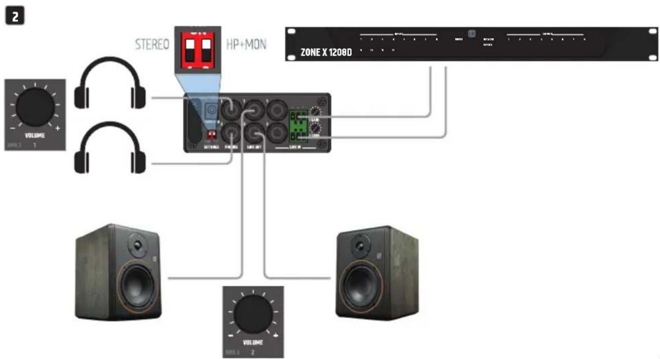
flowchart
graph TD
    A["STEREO"] --> B["HP+MON"]
    C["VOLUME 1"] --> B
    D["VOLUME 2"] --> B
    B --> E["ZONE X 1208D"]
TERMINAL BLOCK CONNECTIONS
CONNECTIONS LINE IN
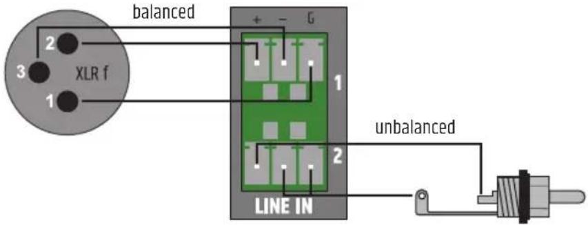

ATTENTION: When wiring terminal blocks, please observe the correct assignment of the poles/terminals. The manufacturer accepts no liability for damage caused by faulty wiring!

Tip: For wiring analogue line inputs and outputs it is preferable to use balanced audio cables.
UNDER / ON-TABLE MOUNTING
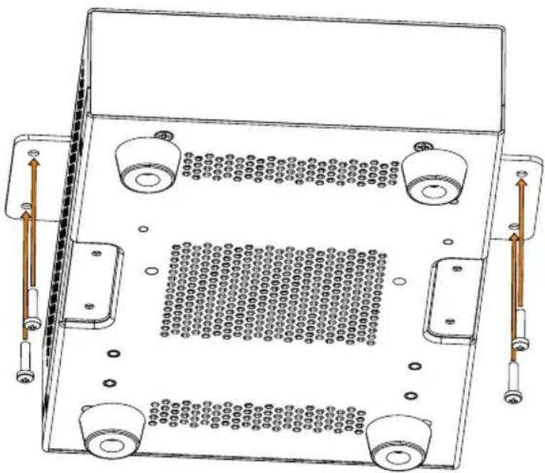
There are two recesses on the top and bottom of the enclosure, each with two M3 threaded holes, for mounting underneath or on top of the table. Screw the two enclosed mounting plates to the top or bottom using the enclosed M3 countersunk screws. Now the amplifier can be fixed in the desired position (see illustration, fixing screws not included). For tabletop mounting, the four rubber feet must be removed beforehand.
natural_image
Technical line drawing of a mechanical or electronic component with four circular ports and mounting holes, showing internal structure and directional arrows (no text or symbols)CARE, MAINTENANCE AND REPAIR
To ensure the proper functioning of the unit in the long term, it must be cared for regularly and serviced as required. The need for care and maintenance depends on the intensity of use and the environment.
We generally recommend a visual inspection before each start-up. Furthermore, we recommend that you carry out all the maintenance measures listed below every 500 operating hours or, in the case of low intensity of use, after one year at the latest. Defects caused by inadequate care may result in limitations of the warranty claims.
CARE (CAN BE CARRIED OUT BY THE USER)
WARNING! Before carrying out any maintenance work, disconnect the power supply and, if possible, all appliance connections.

NOTE! Improper care can lead to impairment or even destruction of the unit.
- Housing surfaces must be cleaned with a clean, damp cloth. Make sure that no moisture can penetrate the unit.
- Air inlets and outlets must be regularly cleaned of dust and dirt. If compressed air is used, make sure that damage to the unit is prevented (e.g. fans must be blocked in this case).
- Cables and plug contacts must be cleaned regularly and freed from dust and dirt.
- In general, no cleaning agents, disinfectants or agents with an abrasive effect may be used for maintenance, otherwise the surface finish may be impaired. Especially solvents, such as alcohol, can impair the function of the housing seals.
- Units should generally be stored in a dry place and protected from dust and dirt.
MAINTENANCE AND REPAIR (BY QUALIFIED PERSONNEL ONLY)
DANGER! There are live components in the device. Even after disconnecting the mains connection, there may still be residual voltage in the device due, for example, to charged capacitors.

PLEASE NOTE! There are no user-serviceable assemblies in the device.

PLEASE NOTE! Maintenance and repair work may only be carried out by sufficiently qualified specialist personnel. If in doubt, consult a specialist workshop.

PLEASE NOTE! Improperly performed maintenance work may affect warranty claims.

PLEASE NOTE! For conversion or retrofit sets provided by the manufacturer, it is essential to observe the enclosed installation instructions.
DIMENSIONS (mm)
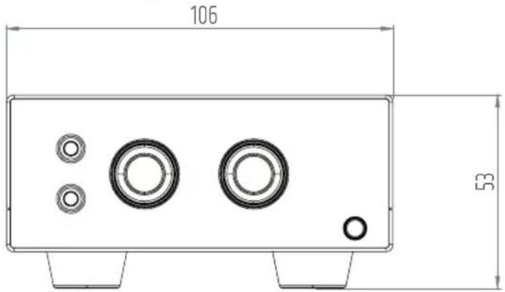
231
TECHNICAL DATA
Item number LDHPA2
Product type Installation Dual Headphone Amplifier
Line inputs 2
Line input connectors Balanced line inputs, pitch 3.81 mm terminal block (3-pin) /
2 x 6.3 mm (1/4") TRS
Line outputs 2
Powered outputs 2 Stereo
Cooling system Convection cooling
Priority levels 1
Input Section
Nominal input sensitivity -9 dBu
Nominal input clipping 17 dBu
THD+N < 0.03%
Input Impedance 15 kOhms (balanced)
SNR > 100 dB (HP1/2 OUT, 14 dBu, 20 kHz BW, A-weighted)
CMRR > 50 dB
Gain Max. 12 dB
Item number LDHPA2
Line Output
Type Balanced
Output Modes Stereo/Mono, HP/HP+MON
Line Out Connector 2 x 6.3 mm (1/4") TRS
Max. Line Output Level 15 dBu
Frequency response 18 Hz - 50 kHz (-0,5 dB)
Headphone Amplifier Output
Type Capless Output
Output Modes Stereo/Mono, HP/HP+MON
HP Out Connector 2 x 6.3 mm (1/4") TRS or 2 x 3.5 mm (1/8") TRS
RMS output power 2 x 75 mW @ 33 Ohm
Minimum Load Impedance 16 Ohms
Frequency response 18 Hz - 50 kHz (-0,5 dB)
Power Supply
Type External SMPS
Voltage Range 100 VAC - 240 VAC (+-10%), 50 - 60 Hz
Mains fuse None
Secondary Voltage 24 V DC
Secondary Current 0.5 A
Secondary Connector Barrel Connector 5.5mm / "+" Inside
Primary Connector Ext. Power Supply Interchangeable Plug
Safety Class Class 3
Max power consumption 5 W (sine 1 kHz with 2 x 33 Ohm load)
Idle power consumption 3.5 W (no signal input)
Standby power consumption < 1 W
Mains Inrush Current 1.7 A @ 230 VAC
Operating Temperature 0^ - 40^ ; < 85% humidity, non condensing
General
Material Steel chassis, Plastic Front panel
Dimensions (W x H x D) 106 (W) x 53 (H) x 225 (D) mm (height with rubber feet)
Weight 0.850 kg
Included Accessories External power supply with Interchangeable Plugs, Mounting plates for surface mount applications, Terminal blocks for Electrical Connections
DISPOSAL

Packaging:
- Packaging can be fed into the reusable material cycle using the usual disposal methods.
- Please separate the packaging in accordance with the disposal laws and recycling regulations in your country.

Device:
- This device is subject to the European Directive on Waste Electrical and Electronic Equipment, as amended. WEEE Directive Waste Electrical and Electronic Equipment. Old devices and batteries can not be disposed of in household waste. The old device or batteries must be disposed of via an authorised waste disposal company or a municipal waste disposal facility. Please observe the applicable regulations in your country!
- Observe all disposal laws applicable in your country.
- As a private customer, you can obtain information on environmentally-friendly disposal options from the seller of the product or the appropriate regional authorities.
MANUFACTURER'S DECLARATIONS
MANUFACTURER'S WARRANTY & LIMITATION OF LIABILITY
Adam Hall GmbH, Adam-Hall-Str. 1, D-61267 Neu Anspach / E-Mail Info@adamhall.com / +49 (0)6081 / 9419-0.
Our current warranty conditions and limitation of liability can be found at:
https://cdn-shop.adamhall.com/media/pdf/MANUFACTURERS-DECLARATIONS_LD_SYSTEMS.pdf.
In case of service, please contact your sales partner.
UKCA-CONFORMITY
Hereby, Adam Hall Ltd. declares that this product meets the following guidelines (where applicable)
Electrical Equipment (Safety) Regulations 2016
Electromagnetic Compatibility Regulations 2016 (SI 2016/1091)
The Restriction of the Use of Certain Hazardous Substances in Electrical and Electronic Equipment Regulation 2012 (SI 2012/3032)
Radio Equipment Regulations 2017(SI 2016/2015)
UKCA-DECLARATION OF CONFORMITY
Products that are subject to Electrical Equipment(Safety)Regulation 2016, EMC Regulation 2016 or RoHS Regulation can be requested at info@adamhall.com. Products that are subject to the Radio Equipments Regulations 2017 (SI2017/1206) can be downloaded from
www.adamhall.com/compliance/
CE CONFORMITY
Adam Hall GmbH hereby confirm that this product meets the following guidelines (where applicable):
R&TTE (1999/5/EC) or RED (2014/53/EU) as of June 2017.
Low Voltage Directive (2014/35/EU)
EMC Directive (2014/30/EU)
RoHS (2011/65/EU)
The complete Declaration of Conformity can be found at www.adamhall.com.
Furthermore, you can also request it at info@adamhall.com.
CE DECLARATION OF CONFORMITY
Declarations of conformity for products subject to the LVD, EMC, RoHS Directive can be requested from info@adamhall.com.
Declarations of conformity for products subject to RED Directive
can be downloaded from www.adamhall.com/compliance/.
DEUTSCH
flowchart
graph TD
    A["STEREO"] --> B["HP"]
    B --> C["STEREO"]
    C --> D["HP"]
    D --> E["STEREO"]
    E --> F["HP"]
    F --> G["STEREO"]
    G --> H["HP"]
    H --> I["Signal Source"]
    J["VOLUME 1"] --> K["Headphones"]
    L["VOLUME 2"] --> M["Headphones"]
    N["VOLUME 1"] --> O["Headphones"]
    P["VOLUME 2"] --> Q["Headphones"]
    R["VOLUME 1"] --> S["Headphones"]
    T["VOLUME 2"] --> U["Headphones"]
flowchart
graph TD
    A["STEREO"] --> B["HP+MON"]
    C["VOLUME 1"] --> D["AC/DC"]
    E["VOLUME 2"] --> F["AC/DC"]
    G["VOLUME 3"] --> H["AC/DC"]
    I["ZONE X 1208D"] --> J["AC/DC"]
    K["1"] --> L["AC/DC"]
    M["2"] --> N["AC/DC"]
    O["3"] --> P["AC/DC"]
    Q["4"] --> R["AC/DC"]
    S["5"] --> T["AC/DC"]
    U["6"] --> V["AC/DC"]
    W["7"] --> X["AC/DC"]
    Y["8"] --> Z["AC/DC"]
    AA["9"] --> AB["AC/DC"]
    AC["10"] --> AD["AC/DC"]

natural_image
Technical line drawing of a mechanical or electronic component with four mounting holes and a central perforated plate (no text or symbols)
natural_image
Technical line drawing of a mechanical or electronic component with four circular ports and mounting holes, no text or symbols present.ENTRETIEN, MAINTENANCE ET RÉPARATION
DÉCLARATION DE CONFORMITÉ EU
flowchart
graph TD
    A["STEREO"] --> B["HP"]
    C["STEREO"] --> D["HP"]
    E["STEREO"] --> F["HP"]
    G["STEREO"] --> H["HP"]
    I["Signal Source"] --> J["VOLUME 1"]
    I --> K["VOLUME 2"]
    L["VOLUME 10.0 1"] --> M["VOLUME 1"]
    N["VOLUME 10.0 2"] --> O["VOLUME 2"]
    P["VOLUME 10.0 1"] --> Q["VOLUME 1"]
    R["VOLUME 10.0 2"] --> S["VOLUME 2"]
flowchart
graph TD
    A["STUDIO"] --> B["HP+MON"]
    C["VOLUME"] --> D["Switch"]
    E["VOLUME"] --> F["Switch"]
    G["VOLUME"] --> H["Switch"]
    I["ZONE X 1208D"] --> J["Switch"]
    K["VOLUME"] --> L["Switch"]
    M["VOLUME"] --> N["Switch"]
    O["VOLUME"] --> P["Switch"]
    Q["VOLUME"] --> R["Switch"]
    S["VOLUME"] --> T["Switch"]
    U["VOLUME"] --> V["Switch"]
    W["VOLUME"] --> X["Switch"]
    Y["VOLUME"] --> Z["Switch"]
    style A fill:#f9f,stroke:#333
    style B fill:#ccf,stroke:#333
    style C fill:#cfc,stroke:#333
    style D fill:#fcc,stroke:#333
    style E fill:#cff,stroke:#333
    style F fill:#ffc,stroke:#333
    style G fill:#fcc,stroke:#333
    style H fill:#cff,stroke:#333
    style I fill:#ffc,stroke:#333
    style J fill:#cfc,stroke:#333
    style K fill:#fcc,stroke:#333
    style L fill:#cfc,stroke:#333
    style M fill:#fcc,stroke:#333
    style N fill:#cfc,stroke:#333
    style O fill:#fcc,stroke:#333
    style P fill:#cfc,stroke:#333
    style Q fill:#fcc,stroke:#333
    style R fill:#cfc,stroke:#333
    style S fill:#fcc,stroke:#333
    style T fill:#cfc,stroke:#333

natural_image
Technical line drawing of a mechanical or electronic component with four ports and mounting holes, no text or symbols present.12 SIG 1 + 2 (SYGNAL)

natural_image
Technical line drawing of a mechanical component with mounting holes and internal grid pattern (no text or symbols)PIELEGNACJA, KONSERWACJA I NAPRAWA

natural_image
Technical line drawing of a mechanical or electronic component with four circular ports and mounting holes, showing internal structure and directional arrows (no text or symbols)- DEUTSCH
- ABOUT THIS MANUAL
- INTENDED USE
- EXPLANATIONS OF TERMS AND SYMBOLS
- SAFETY INSTRUCTIONS
- DANGER:
- WARNING:
- ATTENTION:
- ATTENTION HIGH VOLUMES WITH AUDIO PRODUCTS!
- NOTES FOR INDOOR INSTALLATION EQUIPMENT
- PACKAGING CONTENT
- INTRODUCTION
- FEATURES
- CONNECTIONS, OPERATING AND DISPLAY ELEMENTS
- POWER IN
- STRAIN RELIEF
- LINE IN 1 + 2
- LINE IN 1 + 2
- GAIN 1 + 2
- LINE OUT 1 + 2
- HEADPHONES 1 + 2
- SETTINGS
- ON / OFF SWITCH AND POWER SYMBOL
- HEADPHONES 1 + 2
- VOLUME 1 + 2
- SIG 1 + 2 (SIGNAL)
- CLIP 1 + 2
- AIR VENTS
- TERMINAL BLOCK CONNECTIONS
- CONNECTIONS LINE IN
- UNDER / ON-TABLE MOUNTING
- CARE, MAINTENANCE AND REPAIR
- TECHNICAL DATA
- Item number LDHPA2
- Input Section
- Line Output
- Headphone Amplifier Output
- Power Supply
- General
- DISPOSAL
- Packaging:
- Device:
- MANUFACTURER'S DECLARATIONS
- MANUFACTURER'S WARRANTY & LIMITATION OF LIABILITY
- UKCA-CONFORMITY
- UKCA-DECLARATION OF CONFORMITY
- CE CONFORMITY
- CE DECLARATION OF CONFORMITY
- ENTRETIEN, MAINTENANCE ET RÉPARATION
- DÉCLARATION DE CONFORMITÉ EU
- SIG 1 + 2 (SYGNAL)
- PIELEGNACJA, KONSERWACJA I NAPRAWA
Brand : LD Systems
Model : HPA 2
Category : Audio Amplifier