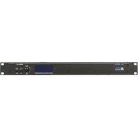
AC26N - Audio processor DB Technologies - Free user manual and instructions
Find the device manual for free AC26N DB Technologies in PDF.


User questions about AC26N DB Technologies
0 question about this device. Answer the ones you know or ask your own.
Ask a new question about this device
Download the instructions for your Audio processor in PDF format for free! Find your manual AC26N - DB Technologies and take your electronic device back in hand. On this page are published all the documents necessary for the use of your device. AC26N by DB Technologies.
USER MANUAL AC26N DB Technologies
REMOTE CONTROLLED AUDIO PROCESSOR
RDNET
text_image
ACOS N dB RESET
A.E.B. INDUSTRIALE s.r.l.
Via Brodolini, 8 - 40056 Crespellano (Bo) - ITALIA
Tel. +39 051 969870 - Fax. +39 051 969725
Internet: www.dblechnologies.com
E-mail: info@dbtechnologies-aeb.com
USER MANUAL - Section 1
natural_image
Line drawing of a rectangular electronic device with ports and a central display (no text or symbols)
text_image
AC 80N 1234COMANDI E FUNZIONI
1) DISPLAY
natural_image
Line drawing of a multi-chamber electronic device with ports and connectors (no text or symbols visible)
text_image
5 6 7 8 9 10 11 12 13 14 15 16 17 A B C D E F G H I J K L M N O P Q R S T U V W X Y ZCOMANDI E FUNZIONI
5) SELETTORE "-6dB"
8) CONNETTORE DI INGRESSO "IN"
9) CONNETTORE DI USCITA "OUT"
text_image
Local A B 1 2 3 4 5 6a) CANALI INGRESSO E USCITA
a) CANALI INGRESSO E USCITA
line
| Parameter | Value | | :--- | :--- | | Threshold | -20.00dB | | Ratio | 1.00:1 | | Post Gain | +0.00dB | | Attack | 20.0mS | | Release | 100.0mS | | Hold | 0.0mS | The chart displays a line graph with a right-side axis labeled '20dB' and a linear trend line with slope 1.1 and slope 2.1, indicating a positive correlation between threshold and output current. The input parameters g₁, g₂, g₃ are listed above the chart.g) Treshold
1.2 corrisponde a 12db/oct
24 corrisponde a 24db/oct
48 corrisponde a 48db/oct
d) FREQUENZA DI TAGLIO
line
| Frequency | Gain Level | | --------- | ---------- | | 0 | 49dB | | 0 | 12dB | | 0 | 24dB | | 0 | 48dB | | 1000 | Peak | | 1000 | Low | | 1000 | High | | 2000 | Low | | 2000 | High | | 3000 | Low | | 3000 | High | | 4000 | Low | | 4000 | High |DESCRIZIONE FINESTRA MENU' "Matrix"
text_image
Ach. Jobs ● Preset X-Over ■ Matrix Option Channel Source Channel Source Out 1: In A Out 4: In B Out 2: In B Out 5: In A+B Out 3: In A+B Out 6: In B a ba) CANALI USCITA
text_image
InA-B Src: An. In Dig.Out Src: An. In Input Link: Indip. Atten. Pad: 8dB Contrast: 60% Fw. Vers: v8.7.11InA-B Src
CMMR: >60dB (50 to 10kHz) Crosstalk: < -100dB
SPDIF-AES/EBU (AES3)
n°1x XLR (3 poli maschio)
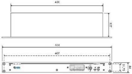
430/482x43x130mm(LxHxD)
1,9Kg
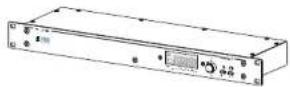
AC26N is a digital sound processor for the management of audio systems, designed for fixed and touring installations. AC26N uses the most modern technology with 28/56 bit processors and high performance 24 bits AD/DA converters.
The functions available in the processor are: input and output levels, delay, polarity, 12 equalization bands for each input and output channel, multiple crossover and high performance limiter.
The control resolution of the filters is 1Hz. Inputs and outputs can be set according to many configurations to meet any need.
AC26N can be controlled in real time and each one of its parameters can be configured on the front panel, and through a computer by means of an intuitive graphical interface, accessible through the software DVA Network and a dedicated RDnet or USB network connection.
The CPU and DSP software update, via PC, allows to keep the device up to date. It is possible to save and recall 32 preset configurations.
Package Contents:
- AC26N
- Operating manual
- Software CD
- Power cord.
Characteristics
- 2 Inputs and 6 Outputs with flexible routing
- AES/EBU addressable stereo inputs and outputs
- 28/56 bit DSP
- BURR-BROWN high performance 24 bit A/D converters
- Frequency resolution of the filters: 1 Hz
- 12 parametric equalizers for each input and output
- 2 crossover filters for each output, with selectable slope 12/24/48 dB/oct
- High performance DRC multi configuration, for limiter/compression configuration of each input and output
- Adjustable level in dB, polarity and delay, for each input and output
- Firmware Update via PC
- Graphic LCD Display
- 32 pre-sets can be stored by the user
- USB interface for configuration and control via computer
- RDnet interface that allows to control up to 256 remote devices
DVA Network
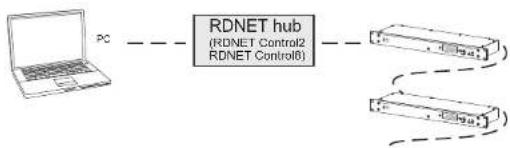
The AC26N is equipped with proprietary network interface, called RDNET, for PC interface through a device (RDNET control).
For this purpose, a proprietary communication protocol has been developed for receiving and sending data; this connection permits real-time monitoring of the diffuser parameters, such as output power, amplifier temperature, limiter status, etc...
It is also possible to select various equalizations or create new ones, set the desired volume levels using the specific plug-in.
It is recommended to download DVA Network free software directly from dB Technologies (www.dbtechnologies.com) in the special section «Software & Controller»
flowchart
graph LR
    PC --> RDNET hub
    RDNET hub --> Device1
    RDNET hub --> Device2
DVA USB Manager
The firmware of the amplifier module can be updated via the USB port.
To make this update possible and simple, a dedicated program has been developed. It is recommended to download DVA USB Manager free software directly from dB Technologies (www.dbtechnologies.com) in the special section «Software & Controller»

text_image
PCFUNCTIONS FRONT PANEL

text_image
AC 80N 1234CONTROLS AND FUNCTIONS
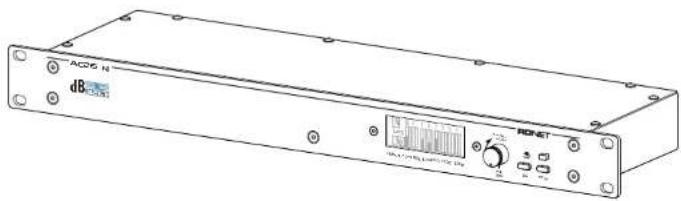
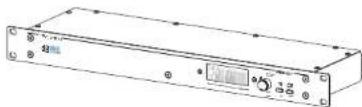
1) DISPLAY
The graphic LCD display allows to view and edit the AC26N information without a computer.
The display contrast can be set within the main menu.
2) "Functions Selector" and "Push Enter" KNOB
This control allows to move, select and change the parameters within the displayed menus.
Rotation of the knob (Function Selector)
- it allows to browse the menu pages;
- it allows to change the selected parameters
Push the knob (Push Enter)
- it allows to select/confirm the parameters
3) ESC button
This control allows to exit the displayed menus or to return to the previous view.
4) MENU button
This control allows to directly access the main menu
text_image
REAR PANEL CONNECTIONS 5 6 7 8 9 10 11 12 13 14 15 16 17CONTROLS AND FUNCTIONS
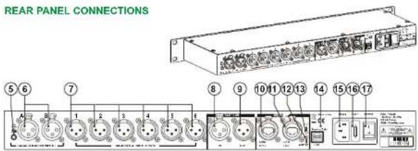
5) -6dB SELECTOR
This selector allows to reduce all the analog XLR [6] input levels by 6 dB at the same time to compensate for the high output levels on the mixers or other audio devices. When the input signal level bar on the display [1] remains always at full scale, this means that the input signal level is excessive and a -6 dB attenuation is recommended. In the Option menu it is possible to check when the selector is activated
6) INPUT CONNECTORS "A" AND "B"
Inputs balanced at line level. Capable to accept XLR male connectors
7) OUTPUT CONNECTORS "1", "2", "3", "4", "5" AND "6"
Outputs balanced at line level. Capable to accept XLR famale connectors

Be careful to correctly connect each output to each speaker or amplifier, according to the settings of each channels, to avoid damages and malfunctions
"AES/EBU" Section
8) INPUT CONNECTOR
In addition to the analog audio inputs, a SPDIF-AES/EBU (AES3) digital audio input is also provided. It can be selected via the setup menu. Such input requires a balanced connection trough an XLR connector with a 110 ohm twisted 3-wires cable.
9) "OUT" OUTPUT CONNECTOR
This connector allows to forward audio signals available at the digital or analog inputs or outputs. The source must be set by means of the Option menu The connection must comply with the same standard of the input [8]
RDNET Section
10) DATAINPUT CONNECTOR
Data input RJ45 connector.
11) "DATA LINK" OUTPUT CONNECTOR
RJ45 connector for data output used for serial link in cascade.
12) "ON" INDICATOR LIGHT
This green indicator turns on only when the AC26N has recognized the RDNET main unit and it is connected to it via computer.
13) "ACTIVE" INDICATOR LIGHT
This yellow indicator flashes when data transmission between RDNET and the device is active.
14) USB connector
This USB connector (type B) allows to connect the processor to a compute, to check and update the firmware via a dedicated program (DVA Network)
15) "MAINS" POWER CONNECTION
It allows to connect the provided power cord
Main power supply fuse housing
17) "POWER" MAIN SWITCH
This switch allows to switch on and off the device
CONNECTIONS
Analog Audio Connections
Balanced connections allow to minimize the cable induced noise, so cable can be longer. Such connections may be used both on inputs and outputs.
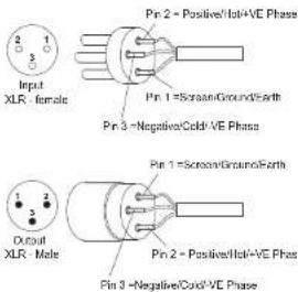
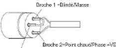
XLR connector must be cabled with pin 1 to ground, pin 2 to hot (+) and pin 3 to cold (-). With shielded cables, connect the shield to pin 1.
XLR-XLR e XLR-Jack 1/4"(6,3 mm) connection cables can be used to connect the AC26N.
text_image
Input XLR - female Pin 2 = Positive/Hot+VE Phase Pin 1 = Screen/Ground/Earth Pin 3 = Negative/Cold+VE Phase Output XLR - Male Pin 1 = Screen/Ground/Earth Pin 2 = Positive/Hot+VE Phase Pin 3 = Negative/Cold+VE Phase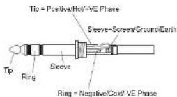
The unbalanced connections can also be used. However, the cable induced noise increases and cable length must not exceed 5 meters.
Such connections may be used both on inputs and outputs.
Unbalanced connection may lower the level of the input signal up to 6dB; in order to overcome this drawback, connect pin 3 to ground, although this can increase the noise.
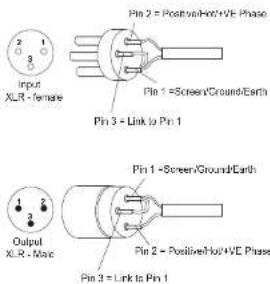
text_image
Input XLR - female Pin 2 = Positive/Hot+VE Phase Pin 1 = Screen/Ground/Earth Pin 3 = Link to Pin 1 Output XLR - Max Pin 1 = Screen/Ground/Earth Pin 2 = Positive/Hot+VE Phase Pin 3 = Link to Pin 1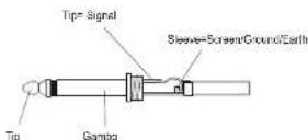
Digital Audio Connections (AES/EBU)
AES/EBU (AES3 protocol) is and a balanced input, electrically insulated by means of a transformer. It allows carrying two audio channels in a single two-wires shielded cable. The cable characteristics are: twisted, 3 poles, impedance 100 ohm, shielded, equipped with XLR connector (AES3 standard)
RDnet
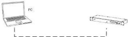
Each RDNet port on Control 2 and Control 8 can be connected to maximum 32 cascade-connected compatible devices.
In the example below, the control unit RDNET CONTROL 2 port is connected to the DATA INPUT of an AC 26N, whose parallel DATA LINK output is sent to the input of the next AC26N.
In the example, [n] is a number between 3 and 32 (maximum limit for the devices connected to a sub-network)
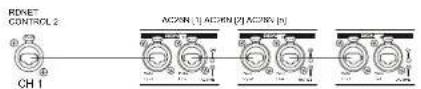
The overall length of a CAT5 sub-network cable cannot exceed 900 meters.
The connector must be connected as follows:
1 - Available for other functions (for example: audio +)
2 - Available for other functions (for example: audio -)
3 - Available for other functions (for example: analog ground)
4 - digital ground
5 - digital ground
6 - Available for other functions (for example: power supply)
7-R3405A
8 - RS 485 B

POWER ON
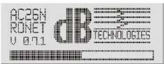
When the device is turned on, the initialization procedure starts. It lasts few seconds. The display shows the device model, the company logo and a program loading progress bar.
text_image
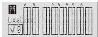
AC26N ROMET V 0.71 dB TECHNOLOGIESAt the end of the installation process the display shows the Meters menu. For further details about the indications, refer to the paragraph MENU DESCRIPTION - METERS.
text_image
Local A B 1 2 3 4 5 6AC26N is now ready for use
CONFIGURATION AND DISPLAY
To access the main menu window, press the MENU key located on the device front panel. In any page of the menu, press the ESC button to return to the previous screen
MAIN MENU
Heters
Preset
Matrix
A Ch. Job
X-Over
Option
There are six menus in the processor. They show and/or configure the system parameters. The main menus are:
Meters Input and output levels display; program in progress display, quick muting
Preset Store, save, and delete the system configurations
Matrix Select the outputs according to the input signal
Ch. Dob
Configuration of the cut-off frequency and the types of filters for each output
Option
Assignment of the inputs and outputs, display contrast, firmware version, inputs and other options
The menus and the individual options displayed can be selected by rotating the knob "FUNCTION SELECTOR" ( ).
To access the selection, highlight the desired parameter and press the "Push Enter" ( | ) knob.
The same procedure should be adopted to select and/or change the options inside each menu entry.
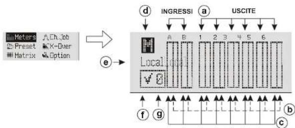
MENU DESCRIPTION - "Meters"
This window allows to view the configuration and the general conditions of the inputs and outputs, the version of the program used, the program status and how the system is driven.
flowchart
graph TD
    A["Meters"] --> B["Ch.Jbb"]
    C["Preset"] --> D["X-Over"]
    E["Matrix"] --> F["Option"]
    B --> G["Local"]
    D --> G
    F --> G
    G --> H["Ingressi"]
    G --> I["USCITE"]
    H --> J["a"]
    I --> K["b"]
    J --> L["1"]
    K --> M["2"]
    L --> N["3"]
    M --> O["4"]
    N --> P["5"]
    O --> Q["6"]
    P --> R["c"]
    Q --> S["f"]
    R --> T["g"]
    S --> U["Output"]
    T --> V["Output"]
a) INPUT AND OUTPUT CHANNELS
The input and output connectors are identified by the same information provided on the screen printing located on the device rear side.
With digital input signals, the indications A and B concern the input.
By rotating the knob FUNCTION SELECTOR [2], input channels, output channels and general muting indications are cyclically scrolled (d); the selected channel is highlighted.
b) BAR COMPRESSION LEVEL/CHANNEL MUTING
SIGNAL COMPRESSION
Signal compression is displayed by the vertical scrolling (top to down) of the right bar
MUTE
Each channel can be individually muted.
Select the channel and press the Push Enter knob [2] to confirm the change of status.
The indication of the channel will be replaced by the letter M and the bar will be completely highlighted.
To restore normal operation, repeal the actions described above.
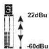
c) SIGNAL LEVEL BAR
The level indication for each channel is provided by scrolling the left bar.
d) GENERAL MUTING
It is possible to mute all the inputs and outputs simultaneously. Rotate the knob FUNCTION SELECTOR, select the letter M and press the Push Enter knob.
To restore normal operation, repeat the actions described above. The general mute has the highest priority with respect to the muting of individual channels
e) CONTROL MODE
It shows how the AC26N is used and/or to which devices it is connected.
Local = stand-alone usage
No connection to an external device
NET = directly connected to dedicated RDnet network and to computer
USB = directly connected to another computer via USB cable
f) SETTING STATUS INDICATION
This indication shows if the loaded program was amended in one or more parameters with respect to the last saving operation.

= original program

= program with modified parameters
g) SET PROGRAM
The number shows the program that is loaded and used by the system, with reference to the saving position. Refer to the "Preset" menu for further details.


MENU DESCRIPTION - CH. JOB
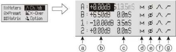
This window allows to view the configuration of each individual channel
text_image
##Meters A Ch. 1gb #Preset X-Diver ##Matrix Option A: +0.00dB 613.5mS M φ ∧ ¬ B: +6.5dB 0.0mS M φ ∧ ¬ 1: -10.00dB 3.5mS M φ ∧ ¬ 2: +0.00dB 0.0mS M φ ∧ ¬ a b c d e f ga) INPUT AND OUTPUT CHANNELS
The input and output connectors are identified by the same information provided on the screen printing located on the device rear side.
b) SIGNAL LEVEL
It shows the signal gain The increased signal intensity is expressed in decibels (dB). Such parameter can be selected in the range from -80.00 dB to +20.00 dB in steps of 0.01 dB.
An increase of 6 dB is approximately equal to doubling - in a linear scale - the signal voltage level
If the gain exceeds 0 dB the signal is amplified, while if the gain is lower than 0 dB the signal is attenuated.
c) SIGNAL DELAY
The reproduced audio signal may be delayed to perform an acoustic alignment. This compensates for the different positions of the speakers during the installation and the sound reproduction; it is expressed in ms. The parameter can be selected in the range from 0.0 ms to 72.9 ms in steps of 0.1 ms.
The following formula can be used to align an audio signal:
Delay = (GAPx1000)/344
Delay = ms (in milliseconds)
GAP = distance between speaker and reference point (in meters)
Speed of sound = 344 m/s
d) MUTE
Each channel can be individually muted. The same command can be activated in the Meters Menu.
NOTE: The general mute has the highest priority with respect to the muting of individual channels.
e) Phase
It performs a phase rotation of 180^ with respect to the input signal.
Such phase rotation allows the optimization, in special way for low frequencies in complex installations.
f) EQUALIZATION
This control opens the menu controlling the single channel equalization. It is mainly used to correct one or more frequencies that must be reduced or increased.
The AC26N manages 12 filters for each individual channel input and output, with three different kinds of configuration:
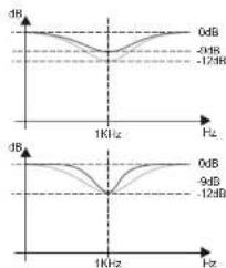
- PEQ Equaliser (peaking equalizer); ideal to identify, isolate and correct only a certain range of frequencies. All frequencies pass, only those around the centre frequency are increased and decreased, for a given bandwidth and set gain.
- High-shelf Equalizer. All frequencies pass, but frequencies above the selected cut-off frequency are increased or attenuated by the given gain.
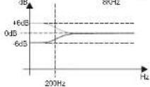
- Low-shelf Equalizer. All frequencies pass, but frequencies below the selected cut-off frequency are increased or attenuated by the given gain.
text_image
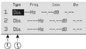
Type Freq. Gain Bu 1 Dis. ---Hz ---,--dB --- 2 Dis. ----Hz ---,--dB --- 3 Dis. ----Hz ---,--dBf, Numbering of the 12 available filters for the specific input or output
f.Displays the kind of filter
□is. Switched off (not present)
PEQ Peaking equilizer
Sh. H High-shelfFilter
Sh. L. Low-shelf Filter
Examples: PEQ Peaking equilizer
| Type | Freq. | Gain | Bw |
| PED | 1000Hz | -12.00dB | 1.00 |
| PED | 1000Hz | -9.00dB | 1.00 |
NOTE
The parameter Bw defines the range of frequencies close to the set frequency where the filter is activated; the greater the value of Bw, the wider is the frequencies range (1 Bw = 1 octave).
| Type | Freq. | Gain | Bx |
| PED | 1000Hz | -12.00dB | 1.00 |
| PED | 1000Hz | -12.00dB | 5.00 |
Sh. H Filtro high-shelf
| Type | Freq. | Gain |
| Sh. H | 9000Hz | -10.00dB |
| Sh. H | 9000Hz | +10.00dB |
Sh. L Filtro low-shelf
| Type | Freq. | Gain |
| Sh. L | 200Hz | -6.00dB |
| Sh. L | 200Hz | +6.00dB |
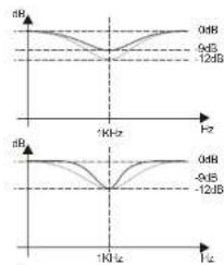
line
| Frequency (Hz) | 0dB | 9dB | -12dB | |---|---|---|---| | 1K Hz | ~0 dB | ~0 dB | ~0 dB | | 1K Hz + 12B | ~0 dB | ~0 dB | ~0 dB |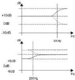
line
| Frequency | Value Label | | --------- | ----------- | | 200Hz | +6dB | | 200Hz | 0dB | | 200Hz | -6dB | | 8kHz | +10dB | | 8kHz | -10dB |g) COMPRESSION
This control opens the menu controlling the compression for the single channel.
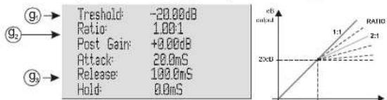
line
| Metric | Value | | :--- | :--- | | Threshold | -20.00dB | | Ratio | 1.00:1 | | Post Gain | +0.00dB | | Attack | 20.0mS | | Release | 100.0mS | | Hold | 8.0mS | The chart includes a secondary axis labeled 'c6' and 'RATIO', with annotations '1:1' and '2:1' indicating the ratio scale.g1) Threshold
Identifies the starting threshold for the compression ratio. Base value 1:1
g2) Ratio
Indicates the conversion ratio between input and output signal.
g3) Post Gain / Attach / Release / Hold
These data are in function of the conversion ratio to achieve:
Post Gain is the output gain
Attack is the attack time
Release is the release time
Hold is the holding time
MENU DESCRIPTION - PRESET
This window allows to store up to 32 configurations in the AC26N.
The manufacturer provides the system with a program set and saved in position 0, that is not possible to overwrite.
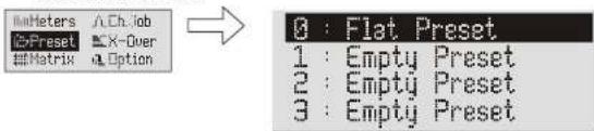
text_image
Meters A.Ch.Job C:Preset X-Over Matrix Option 0 : Flat Preset 1 : Empty Preset 2 : Empty Preset 3 : Empty Preset0...32 Indicates the location where the configuration is saved.
This number also appears in the window Meters in position (g). The program in use can be displayed at any time by the user
Empty Preset It is the name associated with the location number when no setting is saved (empty)
Local preset It is the name associated with the location number when a setting is saved.
NOTE = It is possible to save a setting with the desired name, up to 16 letters, only via the computer interface
When a program is selected, the following window is displayed:
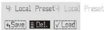
The name of the assigned program is displayed.
3 possible choices are available when working on the application:
Save The program is saved in the AC 26N memory
Del The program is deleted
Load The program is loaded and ready to be used
MENU DESCRIPTION - X-OVER
This window allows to select for each output a low pass filter, a high pass filter, or create a band-pass filter via the combination of both.
The available filter is a Linkwitz-Riley, where it is possible to select slopes of 12 dB/oct, 24 dB/oct or 48 dB/oct and their cut-off frequency.
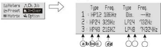
text_image
H/Meters A.Ch.Jab Preset X-Over Matrix Option Type Freq. Type Freq. 1: HP12 130Hz Dis. --Hz 2: HP24 329Hz LP24 732Hz 3: HP48 216Hz LP48 7432Hz a b c c dd o o oa) OUTPUT CHANNELS
The output connectors are identified by the same information provided on the screen printing located on the device rear side.
b) CROSSOVER FILTER
Select the filter according to needs. It is possible to select:
Dis. No filter enabled
HP High-pass filter: set it to allow only the part of audio signal above the cut-off frequency
L.P Low-pass filter: set to allow only the part of audio signal below the cut-off frequency
| Filter configuration Low-pass | High-pass | ||
| Nothing | Dis. | Dis. | |
| High-pass | HP | Dis. | |
| Low-pass | Dis. | LP | |
| Band-pass | HP | LP | |
c) ATTENUATION SLOPE
Select the attenuation slope of the audio signal on the basis of the desired attenuation.
The higher the attenuation slope, at the same cut-off frequency, the greater the signal selection.
It is possible to select:
12 equal to 12 dB/oct
24 equal to 24 dB/oct
48 equal to 48 dB/oct
d) CUT-OFF FREQUENCY
To set the passing frequency for the lower frequencies only (low-pass filter) or the higher frequencies only (high-pass filter).
The choice of the cut-off depends on the desired sound reproduction
The unit of measurement used is Hz.

line
| Input Frequency | Gain (dB) | | --------------- | --------- | | 0 | - | | 10 | - | | 20 | - | | 30 | - | | 40 | - | | 50 | - | | 60 | - | | 70 | - | | 80 | - | | 90 | - | | 100 | - | | 110 | - | | 120 | - | | 130 | - | | 140 | - | | 150 | - | | 160 | - | | 170 | - | | 180 | - | | 190 | - | | 200 | - | | 210 | - | | 220 | - | | 230 | - | | 240 | - | | 250 | - | | 260 | - | | 270 | - | | 280 | - | | 290 | - | | 300 | - | | 310 | - | | 320 | - | | 330 | - | | 340 | - | | 350 | - | | 360 | - | | 370 | - | | 380 | - | | 390 | - | | 400 | - | | 410 | - | | 420 | - | | 430 | - | | 440 | - | | 450 | - | | 460 | - | | 470 | - | | 480 | - | | 490 | - | | 500 | - | | 510 | - | | 520 | - | | 530 | - | | 540 | - | | 550 | - | | 560 | - | | 570 | - | | 580 | - | | 590 | - | | 600 | - | | 610 | - | | 620 | - | | 630 | - | | 640 | - | | 650 | - | | 660 | - | | 670 | - | | 680 | - | | 690 | - | | 700 | - | | 710 | - | | 720 | - | | 730 | - | | 740 | - | | 750 | - | | 760 | - | | 770 | - | | 780 | - | | 790 | - | | 800 | - | | 810 | - | | 820 | - | | 830 | - | | 840 | - | | 850 | - | | 860 | - | | 870 | - | | 880 | - | | 890 | - | | 900 | - | | 910 | - | | 920 | - | | 930 | - | | 940 | - | | 950 | - | | 960 | - | | 970 | - | | 980 | - | | 990 | - | | 1000 | - |MENU DESCRIPTION - MATRIX
For each output, it allows to select the input signal to use as the source.
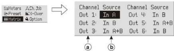
flowchart
graph TD
    A["Input Fields: Meters, ACh.Job, Preset, X-Over, Matrix"] --> B["Channel Source"]
    B --> C["Out 1: In A"]
    B --> D["Out 2: In B"]
    B --> E["Out 3: In A+B"]
    B --> F["Out 4: In B"]
    B --> G["Out 5: In A+B"]
    B --> H["Out 6: In B"]
    I["Input Options"] --> J["a"]
    I --> K["b"]
a) OUTPUT CHANNELS
Identification of the output channel to set
b) IDENTIFICATIONS OF THE INPUTS
It selects the type of signal to match each output, as needed. It is possible to select:
In R Associated with the input signal "A"
In B Associated with the input signal "B"
In A+B Associated with the algebraic sum of the two input signals "A" and "B"
MENU DESCRIPTION - OPTION
Allows to display the system settings, such as the allocation of the inputs and outputs, attenuation, display contrast and firmware version
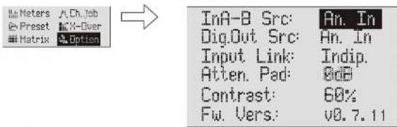
text_image
InA-Meters A Ch.Job @ Preset M X-Over Matrix M Option InA-B Src: An. In Dig.Out Src: An. In Input Link: Indip. Atten. Pad: Bid Contrast: 60% Fw. Vers: v8.7.11InA-B Src
This option allows to set the type of input audio signal.
An. In = Analog audio signals (inputs A and B)
Dig.In = Digital audio signals (AES/EBU input)
Diq.Out Src
This option allows to select the audio source that will be forwarded to the connector AES/EBU OUT (digital output)
An. In = Audio signals available at analog inputs
Dig. In = Audio signals available at digital inputs
OUT 1-2 = Audio signals available on outputs 1 and 2
OUT 3-4 = Audio signals available on outputs 3 and 4
OUT 5-6 = Audio signals available on outputs 5 and 6
Input Mode
It allows to configure the inputs.
Indip. = They are independent, not subject to constraints of any kind between them
Linked = They are connected and work in stereo mode
Compressors, filters, delays, volume... are identical for the two channels
Atten. Pad
It shows how to set the -6 dB switch located on the rear side [Ref. 5]. It is necessary to activate this selector when the analog input levels are too high. The selector can be activated only by means of the button; the menu is for display only.
8 dB = Selector not activated.
The input signals are the same as the input source
-6 dB = Selector activated.
The input signals are attenuated by -6 dB with reference to the inner processor
Contrast
Allows to adjust the LCD display contrast to compensate for the brightness difference at the installation sites. Greater display brightness allows to navigate correctly and quickly within the menu.
The manufacturer output setting is 60%
18%
More bright
60%
More dark
1.00%
Fw. Vers.
It shows the processor firmware version
TECHINICAL SPECIFICATION
AUDIO PERFORMANCE
Frequency Response: +/-0.1dB (20 to 30kHz)
Dynamic Range: 116dB typ
CMMR: >00GB,50T Copyrightly: 100dB
Distortion: 0.002% (1kHz @+4dBu)
DIGITAL AUDIO PERFORMANCE
Processor: DSP 26/58-bil
Data processing Frequency: 24-bit BURR BROWN
Analog converters:
Propagation Delay. Storing configurations:
CONTROLS
n°2 x XLR (3 pole female)
10KOhm
2100 senza PAD
n°6×YLR/3 pole ma
500hm
+21dB
Balanced
n*1x XLR (3 pole female)
SPDIF-AES/EBU (AES3)
n 1x XLR (3 pole male)
Compliant with the input standard n°2×XLRP45(CAT5 cable)
Tino B
-80dB a +20dB step 0,1dB
0a72,9mS step 0,1mS
0a340mS step 0.1mS
0° - 180°
COMPRESSION
Threshold
Ratio
Outperform attack time
Release time
Hold time
-80dB a +20dB step 0.1dB
1:1 a int:1 step 0.01
0dB a40dB step 0.1dB
1ms a 1000ms step 0,1ms
1mS a 1000mS step 0.1mS
EQUALIZERS
12 equalizers for each input and output
type
Frequency
Gain
CROSSOVER FILTERS
Filter
Type:
Linkwitz Riley
HP High-pass
LP Low-pass
12dB/oct - 24dB/oct - 48dB/oct
5Hz a 20kHz passo 1Hz
Slope
CUT-OFF FREQUENCY
Full-range 100-240Vac 50-60Hz
430/482x43x130mm (WxHxD
17/19x1,7x5.1 inch. (WxHxD)
1,9kg
WEIGHT
Note: Specifications subject to change without notice
EMI CLASSIFICATION
According to the standards EN 55103 this equipment is designed and suitable to operate in E3 (or lower E2, E1) Electromagnetic environments.
EINLEITUNG
natural_image
Line drawing of a rectangular electronic device with multiple ports and connectors (no text or symbols visible)
text_image
5 6 7 8 9 10 11 12 13 14 15 16 17 A B C D E F G H I J K L M N O P Q R S T U V W X Y ZBEDIENUNGEN UND FUNKTIONEN
5) WAHLSCHALTER "-6dB"
Digitales Audio (AES/EBU)
c) BALKEN DES SIGNALLEVELS
Sh. L Filter Low-shelf
Type Freq Gain
Sh. L 200Hz -6.00dB
Sh. L 200Hz +5.00dB
line
| Frequency (Hz) | 0dB (dB) | -9dB (dB) | |------------------|----------|----------| | 1K | ~0 | ~0 | | 1KHz | ~-12 | ~-12 |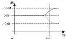
a) KOMPRESSION
text_image
Heters A.Ch.Job Preset X-Over Matrix Option InA-B Src: An. In Dig.Out Src: An. In Input Link: Indip. Atten. Pad: 8dB Contrast: 60% Fw. Vers: v8.7.11InA-B Src
10% heller 60% dunkler 100%
Fw. Vers.
+/-0.1dB (20 to 30kHz)
116dB typ
60dB (50 to 10kHz)
<-100dB
0.002% (1kHz @+4cBu)
DSP 28/56-bit
48KHz
24-bit BURR BROWN
1.5ms 32 pro
32 presc
LCD Grafik
ESC - MENU - FUNCTIONS SELECTION
ENTER
EIN-/AUSGÄNGE
Analoger Eingang n°2 x XLR (3-poliger Female Stecker)
n°1x XLR (3-pollger female Stecker)
SPDIF-AES/EBU (AES3)
n°1x XLR (3-poliger Male Stecker)
-30dB a = 15dB step 0.01dB
0.05dB a 2dB step 0.01dB (lediglich PEQ)
Linkwitz Riley
430/482x43x130mm (BXHXT)
1,9Kg
natural_image
Line drawing of a rectangular electronic device with ports and a central display (no text or symbols)
text_image
AC 80N 1234COMMANDES ET FONCTIONS
1) AFFICHAGE
text_image
5 6 7 8 9 10 11 12 13 14 15 16 17 A B C D E F G H I J K L M N O P Q R S T U V W X Y ZCOMMANDES ET FONCTIONS
5) SELECTEUR "-6dB"
6) CONNECTEURS D'ENTREE "A" ET "B"
Broche 3 = Link to Pin 1
text_image
A B 1 2 3 4 5 6 Local ✓g3) Post Gain/Attach/Release/Hold
text_image
Heter Ch.Job Prasset X-Over Matrix Option Channel Source Channel Source Out 1: In A Out 4: In B Out 2: In B Out 5: In A+B Out 3: In A+B Out 6: In B a ba) CANAUX DE SORTIE
text_image
Meters Ch. lib Preset X-Over Matrix Option InA-B Src: An. In Dig.Out Src: An. In Input Link: Indip. Atten. Pad: @dB Contrast: 60% Fw. Vers: v8.7.11InA-B Src
Distorsion: 0.002% (1kHz @+4dBu)
PERFORMANCES AUDIO NUMERIQUES
Entrees/Sorde Ronet USB
SOD
PARAMETRES DE CONTROLE DU SON
Gain
Delta
Entrée
SPDIF-AES/EBU (AES3)
n"1x XLR (3 broches male)
IF 2X ALKR45 (cable CAT 3) Type B
HypoS
This is robusts etape 5, this
PEQ (paramétrique) Hi-shelf Lo-sheft
flowchart
graph TD
    A["Speaker 1"] -->|HIGH L| B["Module 1"]
    A -->|MID L| C["Module 2"]
    B -->|HIGH R| D["Speaker 2"]
    B -->|MID R| E["Speaker 3"]
    C -->|LOW L| F["Server"]
    C -->|LOW R| G["Speaker 4"]
    F --> H["Data Bus"]
    G --> I["Data Bus"]
    H --> J["Output 1: Source: In A"]
    H --> K["Output 2: Source: In B"]
    H --> L["Output 3: Source: In A"]
    H --> M["Output 4: Source: In B"]
    H --> N["Output 5: Source: In A"]
    H --> O["Output 6: Source: In B"]
    J --> P["Menu Matrix configuration"]
    K --> P
    L --> P
    M --> P
    N --> P
    O --> P
LINE ARRAY / SUB MONO ATTIVO
LINE ARRAY /SUB MONO ACTIVE

flowchart
graph TD
    subgraph_Server_Rs_1["Server Rack 1"]
        A1["1"] -->|HIGH/MID L| B1["2"]
        A2["2"] -->|HIGH/MID L| B2["3"]
        A3["3"] -->|HIGH/MID L| B3["4"]
        A4["4"] -->|HIGH/MID L| B4["5"]
    end

    subgraph_Server_Rs_2["Server Rack 2"]
        B1["1"] -->|HIGH/MID R| C1["2"]
        B2["2"] -->|HIGH/MID R| C2["3"]
        B3["3"] -->|HIGH/MID R| C3["4"]
        B4["4"] -->|HIGH/MID R| C4["5"]
    end

    subgraph_Server_Rs_3["Server Rack 3"]
        C1["1"] -->|LOW L| D1["6"]
        C2["2"] -->|LOW L| D2["5"]
        C3["3"] -->|LOW L| D3["4"]
        C4["4"] -->|LOW L| D4["3"]
        C5["5"] -->|LOW L| D5["2"]
        C6["6"] -->|LOW L| D6["1"]

    end

    subgraph_Server_Rs_4["Server Rack 4"]
        D1["6"] --> E1["A"]
        D2["5"] --> E2["B"]
        D3["4"] --> E3["L"]
        D4["3"] --> E4["R"]
        D5["2"] --> E5["A"]
        D6["1"] --> E6["B"]
    end

    style Server_Rs_1 fill:#f9f,stroke:#333
    style Server_Rs_2 fill:#f9f,stroke:#333
    style Server_Rs_3 fill:#f9f,stroke:#333
    style Server_Rs_4 fill:#f9f,stroke:#333
    style Server_Rs_5 fill:#f9f,stroke:#333
    style Server_Rs_6 fill:#f9f,stroke:#333
    style Server_Rs_7 fill:#f9f,stroke:#333
    style Server_Rs_8 fill:#f9f,stroke:#333
    style Server_Rs_9 fill:#f9f,stroke:#333
    style Server_Rs_10 fill:#f9f,stroke:#333
    style Server_Rs_11 fill:#f9f,stroke:#333
    style Server_Rs_12 fill:#f9f,stroke:#333
    style Server_Rs_13 fill:#f9f,stroke:#333
    style Server_Rs_14 fill:#f9f,stroke:#333
    style Server_Rs_15 fill:#f9f,stroke:#333
    style Server_Rs_16 fill:#f9f,stroke:#333
    style Server_Rs_17 fill:#f9f,stroke:#333
    style Server_Rs_18 fill:#f9f,stroke:#333
    style Server_Rs_19 fill:#f9f,stroke:#333
    style Server_Rs_20 fill:#f9f,stroke:#333
    style Server_Rs_21 fill:#f9f,stroke:#333
    style Server_Rs_22 fill:#f9f,stroke:#333
    style Server_Rs_23 fill:#f9f,stroke:#333
    style Server_Rs_24 fill:#f9f,stroke:#333
    style Server_Rs_25 fill:#f9f,stroke:#333
    style Server_Rs_26 fill:#f9f,stroke:#333
    style Server_Rs_27 fill:#f9f,stroke:#333
    style Server_Rs_28 fill:#f9f,stroke:#333
    style Server_Rs_29 fill:#f9f,stroke:#333
    style Server_Rs_30 fill:#f9f,stroke:#333
    style Server_Rs_31 fill:#f9f,stroke:#333
    style Server_Rs_32 fill:#f9f,stroke:#333
    style Server_Rs_33 fill:#f9f,stroke:#333
    style Server_Rs_34 fill:#f9f,stroke:#333
    style Server_Rs_35 fill:#f9f,stroke:#333
    style Server_Rs_36 fill:#f9f,stroke:#333
    style Server_Rs_37 fill:#f9f,stroke:#333
    style Server_Rs_38 fill:#f9f,stroke:#333
    style Server_Rs_39 fill:#f9f,stroke:#333
    style Server_Rs_40 fill:#f9f,stroke:#333
    style Server_Rs_41 fill:#f9f,stroke:#333
    style Server_Rs_42 fill:#f9f,stroke:#333
    style Server_Rs_43 fill:#f9f,stroke:#333
    style Server_Rs_44 fill:#f9f,stroke:#333
    style Server_Rs_45 fill:#f9f,stroke:#333
    style Server_Rs_46 fill:#f9f,stroke:#333
    style Server_Rs_47 fill:#f9f,stroke:#333
    style Server_Rs_48 fill:#f9f,stroke:#333
    style Server_Rs_49 fill:#f9f,stroke:#333
    style Server_Rs_50 fill:#f9f,stroke:#333
line
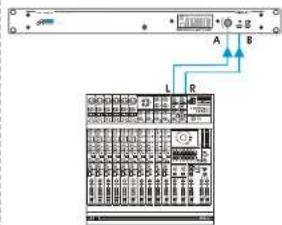
| Frequency (Hz) | Out 1 (dB) | Out 2 (dB) | Out 3 (dB) | |---|---|---|---| | 60 | -0.5 | -0.5 | -0.5 | | 200 | -0.5 | -0.5 | -0.5 | | 2400 | -0.5 | -0.5 | -0.5 | The chart displays a triangular waveform with two distinct peaks labeled 'Out 1' and 'Out 2', and one peak labeled 'Out 3'. The y-axis is labeled 'Quadugno' and the x-axis is labeled 'Frequenza'.INGRESSI - INPUT
Ingresso ANALOGICO
ANALOG Input
text_image
Diagram of a server rack with labeled ports A, B, L and connection points, showing internal components and status indicators.Menu Option configuration
In.A-B Src : An. In
Ingresso DIGITALE DIGITAL input
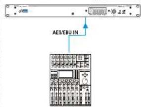
text_image
AES/EBU INMenu Option configuration
In.A-B Src : Dig. In
Input type : PES
PES out : Dig In
Input type : PES
RES out : Dig. In
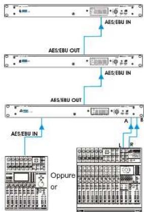
Collegamento in cascata Link connections
Menu Option configurationOption

Oppure
or
Input type : Enalog
RES out : Sn. In
flowchart
graph TD
    A["Server 1"] -->|AES/EBU IN| B["Server 2"]
    B -->|AES/EBU OUT| A
    C["Server 3"] -->|AES/EBU IN| B
    B -->|AES/EBU OUT| C
    D["Server 4"] -->|AES/EBU IN| E["Server 5"]
    E -->|A R| F["Server 6"]
    E -->|L| G["Server 7"]
    E -->|B| H["Server 8"]
    style A fill:#f9f,stroke:#333
    style B fill:#f9f,stroke:#333
    style C fill:#f9f,stroke:#333
    style D fill:#f9f,stroke:#333
    style E fill:#ccf,stroke:#333
    style F fill:#ccf,stroke:#333
    style G fill:#ccf,stroke:#333
    style H fill:#ccf,stroke:#333
DIMENSIONI / DIMENSIONS
ABMESSUNGEN / DIMENSIONS