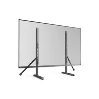
ERTSX1-01B - TV Stand ErgoAV - Free user manual and instructions
Find the device manual for free ERTSX1-01B ErgoAV in PDF.


| Product Type | TV Wall Mount |
| Brand | ErgoAV |
| Model | ERTSX1-01B |
| Maximum Load Capacity | 49.9 kg (110 lb) |
| VESA Compatibility | 200x200 mm to 800x400 mm |
| Material | Steel |
| Mounting Type | Wall mounting on wood studs or concrete |
| Number of Fixing Points | 4 |
| Safety Straps Included | Yes (2) |
| Tools Required (not included) | Screwdriver, hex key, drill, bits, stud finder |
| Adjustable Height | Yes, 4 positions |
| Tilt | No |
| Swivel | No |
| Cable Management | Yes, pre-attached cable ties |
| Warranty | 2 years (subject to conditions) |
| Country of Manufacture | China (estimated) |
Frequently Asked Questions - ERTSX1-01B ErgoAV
User questions about ERTSX1-01B ErgoAV
0 question about this device. Answer the ones you know or ask your own.
Ask a new question about this device
Download the instructions for your TV Stand in PDF format for free! Find your manual ERTSX1-01B - ErgoAV and take your electronic device back in hand. On this page are published all the documents necessary for the use of your device. ERTSX1-01B by ErgoAV.
USER MANUAL ERTSX1-01B ErgoAV
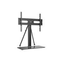
Table Top TV Stand Instruction Manual
V1.0
English pages: 02–14
French pages: 15–27
Spanish pages: 28–40
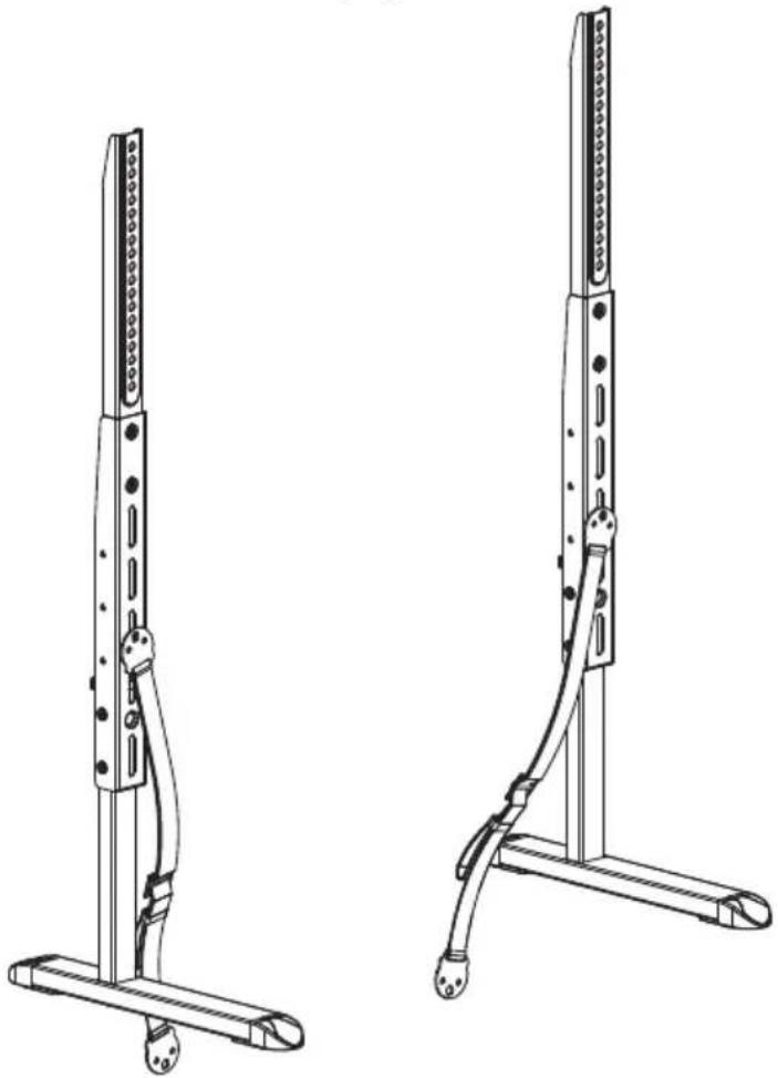
natural_image
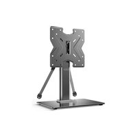
Technical line drawing of two mechanical support structures with no visible text or symbolsModel: ERTSX1-01B
THANK YOU FOR CHOOSING THIS ERGOAV PRODUCT!
At ErgoAV, we want to add value to your AV experience by providing the highest quality products and services in the industry. If you have any concerns or comments, please contact us.
ErgoAV Customer Care
Phone (877) 419-7832 M-F 8am to 8pm CST
email: support@ergoav.com
website: www.ergoav.com
address: 9501 Louisiana Ave N, #200 Brooklyn Park, MN 55445
IMPORTANT SAFETY INFORMATION
CAUTION: Avoid potential personal injuries and property damage!
Do not use this product for any purpose that is not explicitly specified in this manual. Do not exceed weight capacity. We are not liable for damage or injury caused by improper mounting, incorrect assembly or inappropriate use.
Please carefully read all instructions before attempting assembly. If you do not understand the instructions or have any concerns or questions, please contact our Technical Support line at (877) 419-7832 or customer service at support@ergoav.com.
Before getting starting, let's make sure this mount is perfect for you!
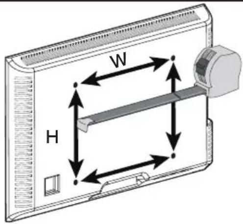
Measure Your TV VESA Pattern:
Minimum: 200 x 200mm/7.9 x 7.9in(W x H)
Maximum: 800 x 400mm/31.5 x 15.7in(W x H)
If your TV is not between the minimum and maximum measurements, do not use this product.
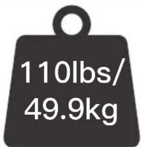
If your TV weighs more than 110 lbs, do not use this product.
For safety strap installations, you will need to verify your wall construction.
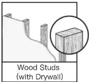
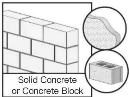

DO NOT install into drywall alone.
If this TV stand is NOT compatible, please contact our Technical Support line at (877) 419-7832 or customer service at support@ergoav.com to find a compatible product.
Tools Needed (Not Included)
For TV stand assembly
Tape Measure
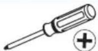
Phillips
Screwdriver
For safety strap installatcon into wood table/furniture and wood stud applications
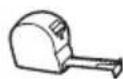
Tape
Measure Pencil
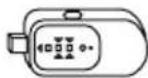

AwlStud Finder
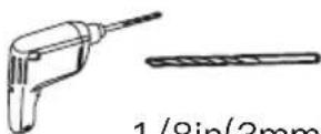
Drill
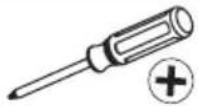
Phillips
Screwdriver
For safety straps installation into concrete wall
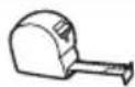
Tape Measure
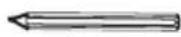
Pencil
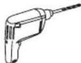
Drill

5/16in(8mm)
Concrete Drill Bit Hammer
Phillips
Screwdriver
Supplied Parts and Hardware
⚠ WARNING: This product contains small items that could be a choking hazard if swallowed.
Before starting assembly, verify all parts are included and undamaged. Do not use damaged or defective parts. If you require replacement parts, please contact our Technical Support line at (877) 419-7832 or customer service at support@ergoav.com.
- PLEASE NOTE: Not all hardware included in this package will be used.
Supplied Parts and Hardware for Step 1
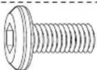
NOTE: The bolt is shown in actual size
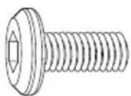
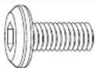
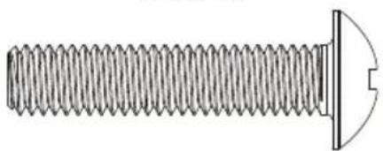
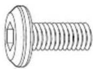
(A) x4 M5x12mm Bolt
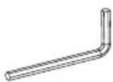
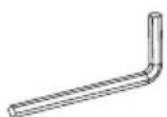
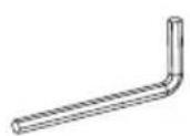
(F) x1
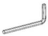
5/32in(4mm)
Allen Key
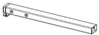
natural_image
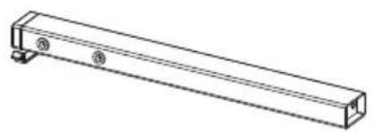
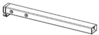
Technical line drawing of a rectangular metal bracket with mounting holes (no text or symbols)03 x2
Support Pillar
natural_image
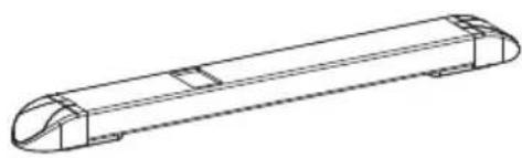
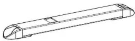
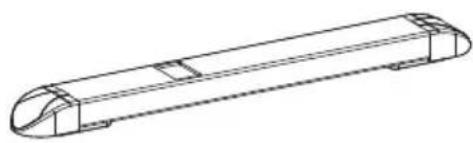
Technical line drawing of a cylindrical mechanical component with flanges and mounting brackets (no text or symbols)04 x2
Base
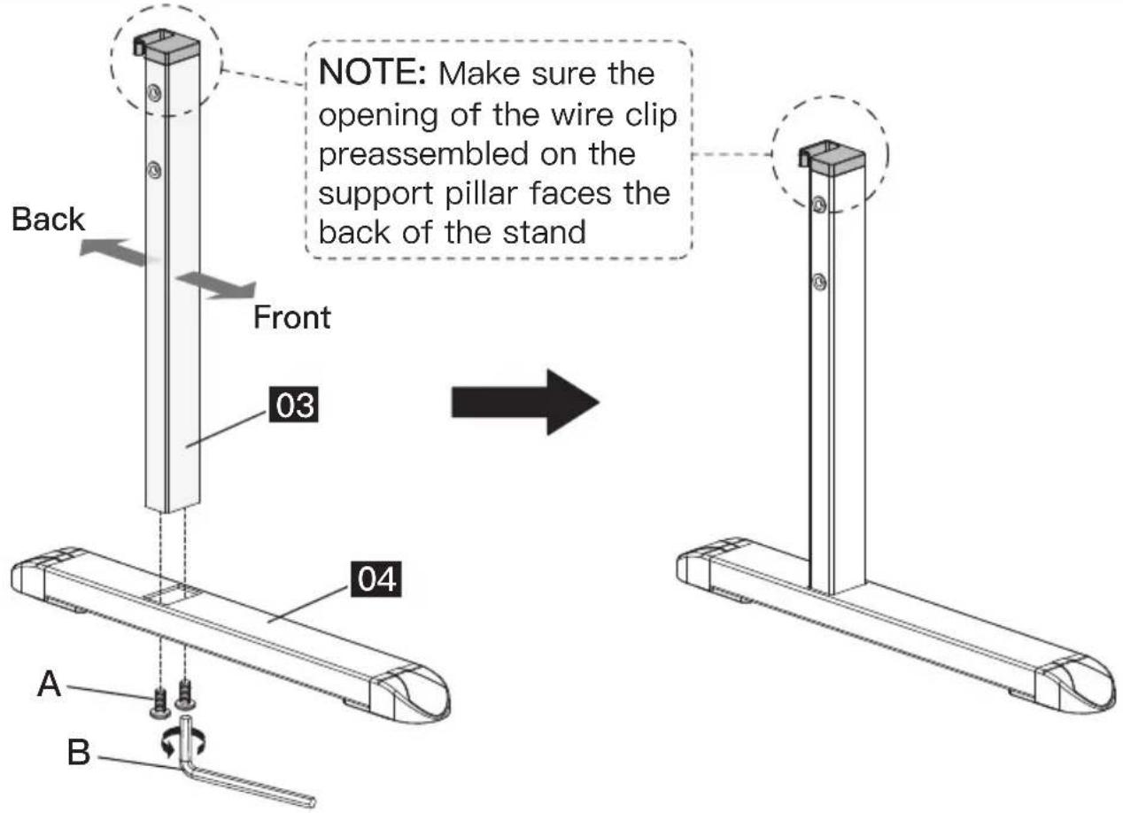
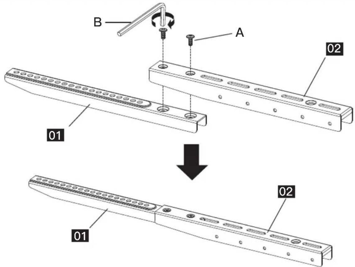
Step 1 Connect the Support Pillar to Base
Supplied Parts and Hardware for Step 2
NOTE: The bolt is shown in actual size
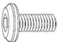
(A) x4
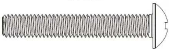
M5x12mm Bolt
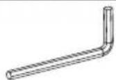
(F) ×1
5/32in(4mm)
Allen Key
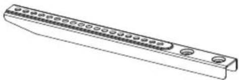
natural_image
Line drawing of a mechanical component with circular end caps and a central shaft (no text or symbols)01 x2
Upper TV Bracket
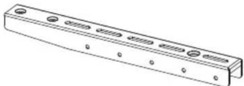
natural_image
Technical line drawing of a rectangular metal bracket with multiple holes and mounting holes (no text or symbols)02 x2
Lower TV Bracket
Step 2 Assemble TV Brackets
Supplied Hardware for Step 3

natural_image
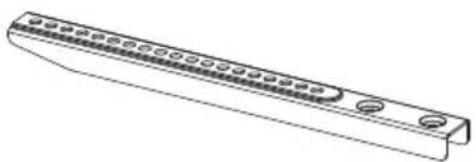
Pure mechanical diagram of a long rod with flanges and central block (no text or symbols)(P) x2 Safety Strap
(B) x4 M6/M8 Washer
Bolts and spacers are shown in actual size.
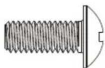
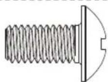
(C1) x4
M6x15mm
Bolt
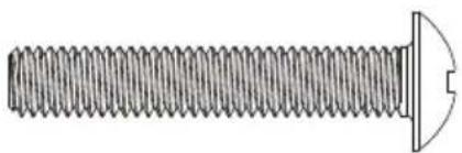
natural_image
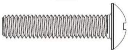
Technical line drawing of a threaded bolt with a flanged end and a circular head (no text or symbols)(C2) x4 M6x35mm Bolt
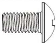
(D1) x4
M8x15mm
Bolt
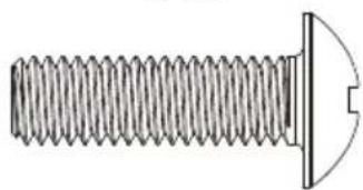
natural_image
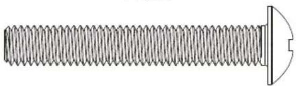
Technical line drawing of a threaded screw with a flat head and a curved tip (no text or symbols)(D2) x4 M8x25mm Bolt
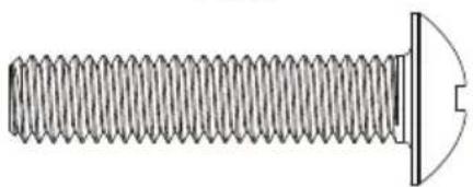
natural_image
Technical line drawing of a threaded bolt with a flanged end and a circular head detail (no text or symbols)(D3) x4 M8x35mm Bolt
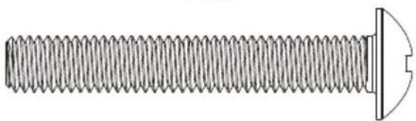
natural_image
Technical line drawing of a threaded bolt with a flanged end (no text or symbols)(D4) x4 M8x50mm Bolt
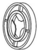
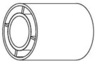
(E1) x8
L2.5mm
Spacer
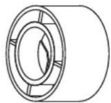
natural_image
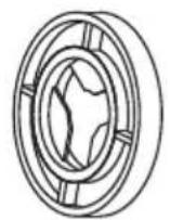
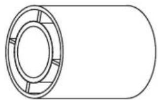
Pure technical line drawing of a cylindrical mechanical component with no text or symbols(E2) x4
L10mm
Spacer
natural_image
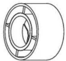
Simple line drawing of a cylindrical mechanical component with flanges and central bore (no text or symbols)(E3) x4
L22mm
Spacer
Step 3 Secure the TV Brackets [N] and the Safety Straps [P] to TV
Select TV Bolts
Only one bolt size fits your TV.
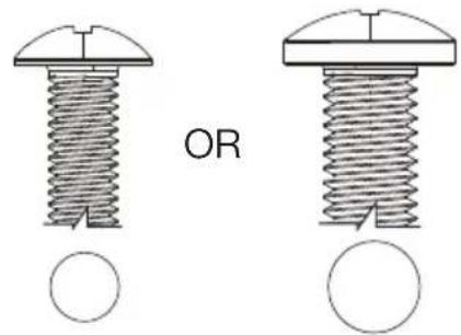
M6 M8

natural_image
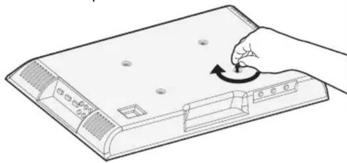
Line drawing of a hand pressing down on a flat-screen computer tower with a circular arrow indicating rotation (no text or symbols)Bolt length: Verify adequate thread engagement with bolts or bolts/spacers combination. We recommend thread engagement by at least 5 turns.
-Too short will not hold the TV.
-Too long will damage the TV.

Too Short Correct Too Long
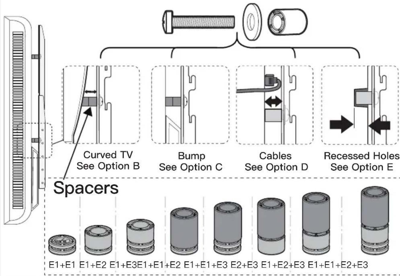
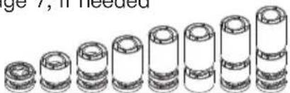
PLEASE NOTE: When using the spacers it is important to note that they can be used in multi-layers (meaning stacked). If you have any difficulty understanding how to install the TV bolts or spacers, please contact our Technical Support line at (877) 419–7832 or customer service at support@ergoav.com.
Parts Needed if You Have a TV as Shown Below
flowchart
graph TD
    A["Spacers"] --> B["Curved TV See Option B"]
    B --> C["Bump See Option C"]
    C --> D["Cables See Option D"]
    D --> E["Recessed Holes See Option E"]
    E --> F["E1+E1"]
    E --> G["E1+E2"]
    E --> H["E1+E3E1+E1+E1+E2"]
    E --> I["E1+E1+E3"]
    E --> J["E2+E3"]
    E --> K["E1+E2+E3"]
    E --> L["E1+E1+E2+E3"]
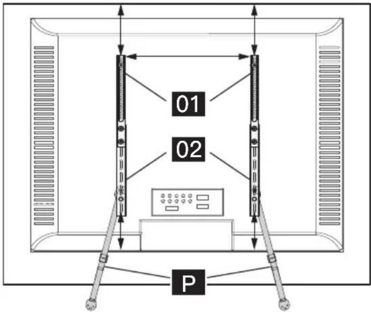
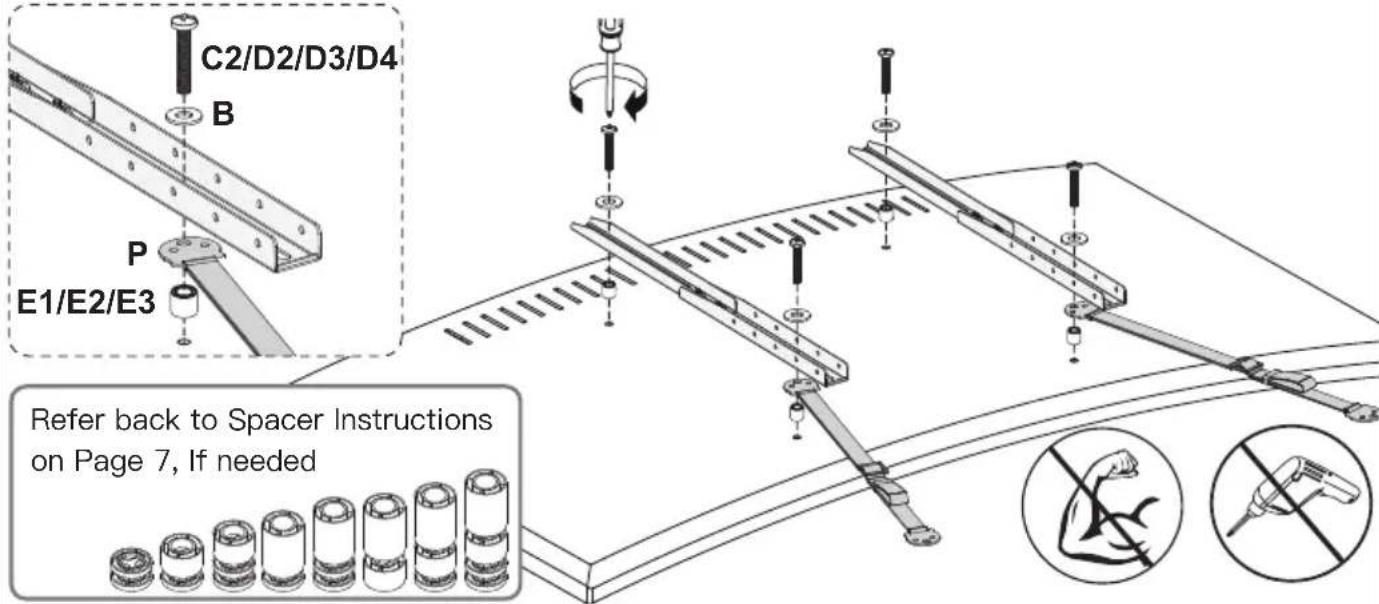
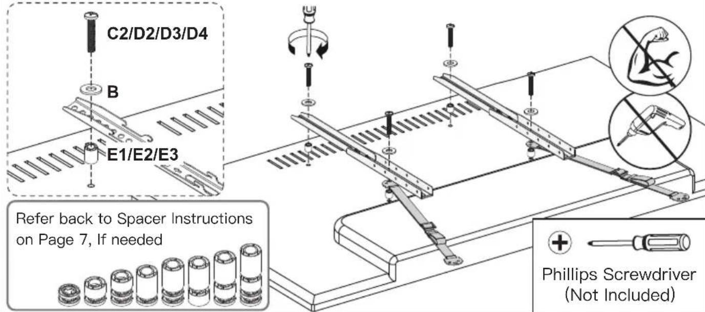
When attaching the TV brackets to the back of the TV, ensure the end with round holes are pointing to the top of the TV and are equally centered on the back of the TV.
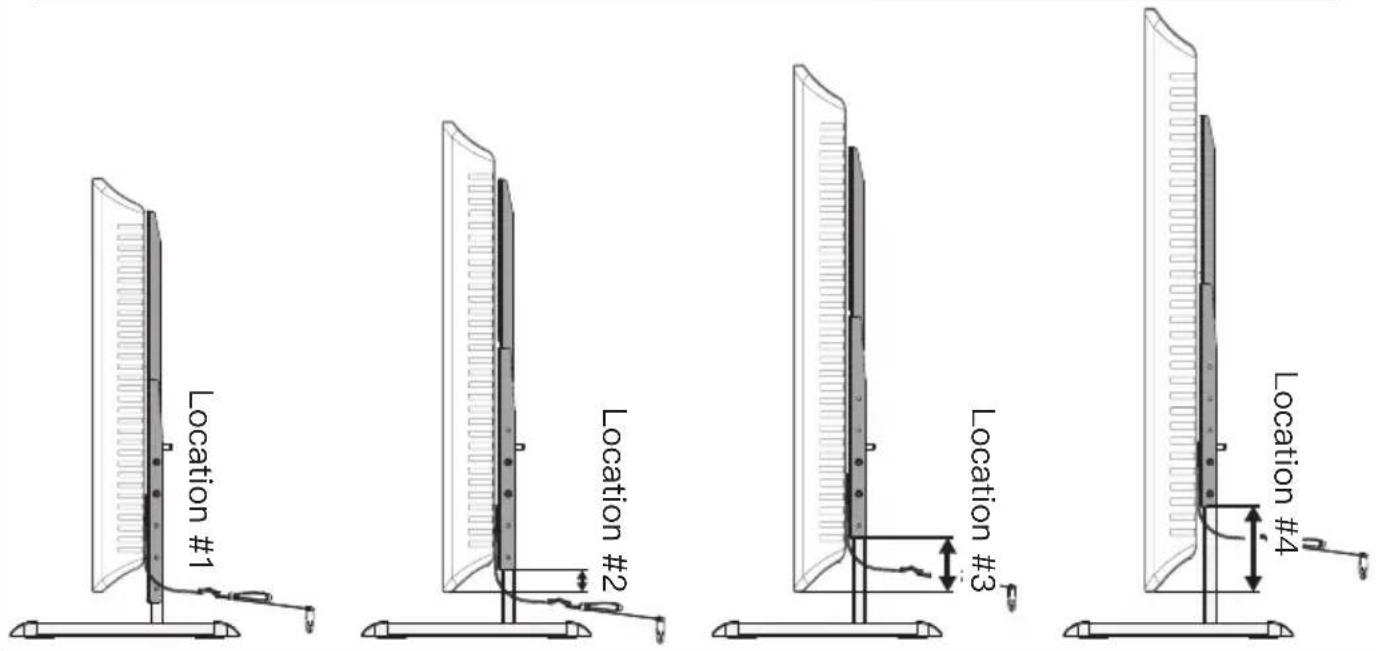
TV Brackets have “four height locations”, which determines the height position of your TV while attaching your TV on the stand in Step 4 on page 10.
You can choose the proper height.
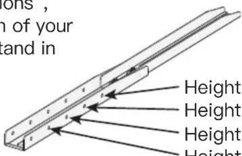
Height Location #1
Height Location #2
Height Location #3
Height Location #4
Option A (For Flat Back TV)
Add a spacer [E1] on the top VESA hole so TV brackets are flush (NO GAP) when the safety straps are attached.
![Option A (For Flat Back TV) Add a spacer [E1] on the top VESA hole so TV brackets are flush (NO GAP) when the safety straps are attached. C1/D1 B P E1](/content/2026/04/727267/images/61095a5bff12679101d529ea867f18d66d55fdc210cf95d0a65df29d4900c6c5.jpg)
Option B (For Curved Back TV)
Option C (For TV with A "Bump")
Spacers must be large enough so TV brackets are flush (NO GAP) on bump
Option D (for TV with Cable Interference)
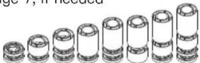
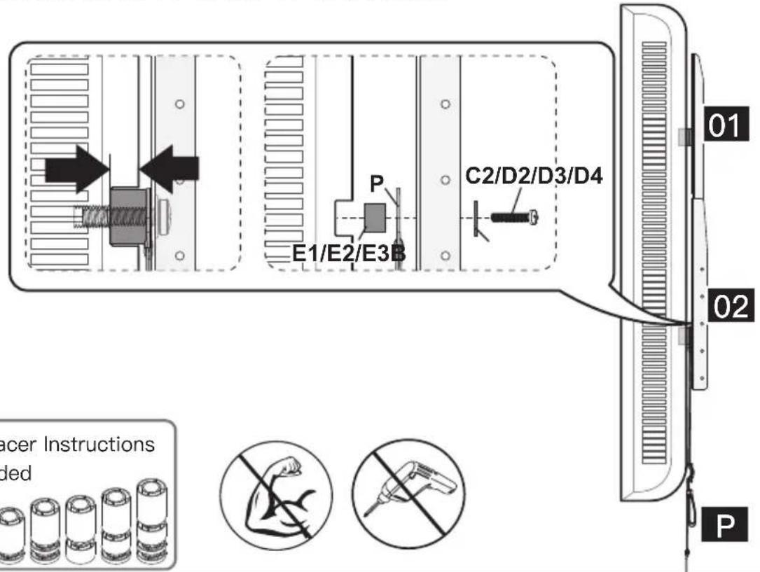
For cable interference, use spacers [E1], [E2] and [E3] to create extra space between the TV and TV brackets

Phillips Screwdriver (Not Included)

Refer back to Spacer Instructions on Page 7, If needed
natural_image
Illustration of stacked cylindrical objects with no text or symbols
Option E (For Recessed Holes)
The spacer need to fill in the recessed holes on the basis of the TV so that the TV brackets are as close to the TV as possible
Refer back to Spacer Instructions on Page 7, If needed

Supplied Part and Hardware for Step 4
NOTE: The bolt is shown in actual size
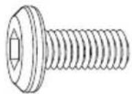
(A) x4 M5x12mm Bolt
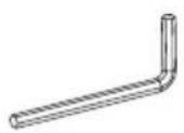
(F) x1 5/32in(4mm) Allen Key
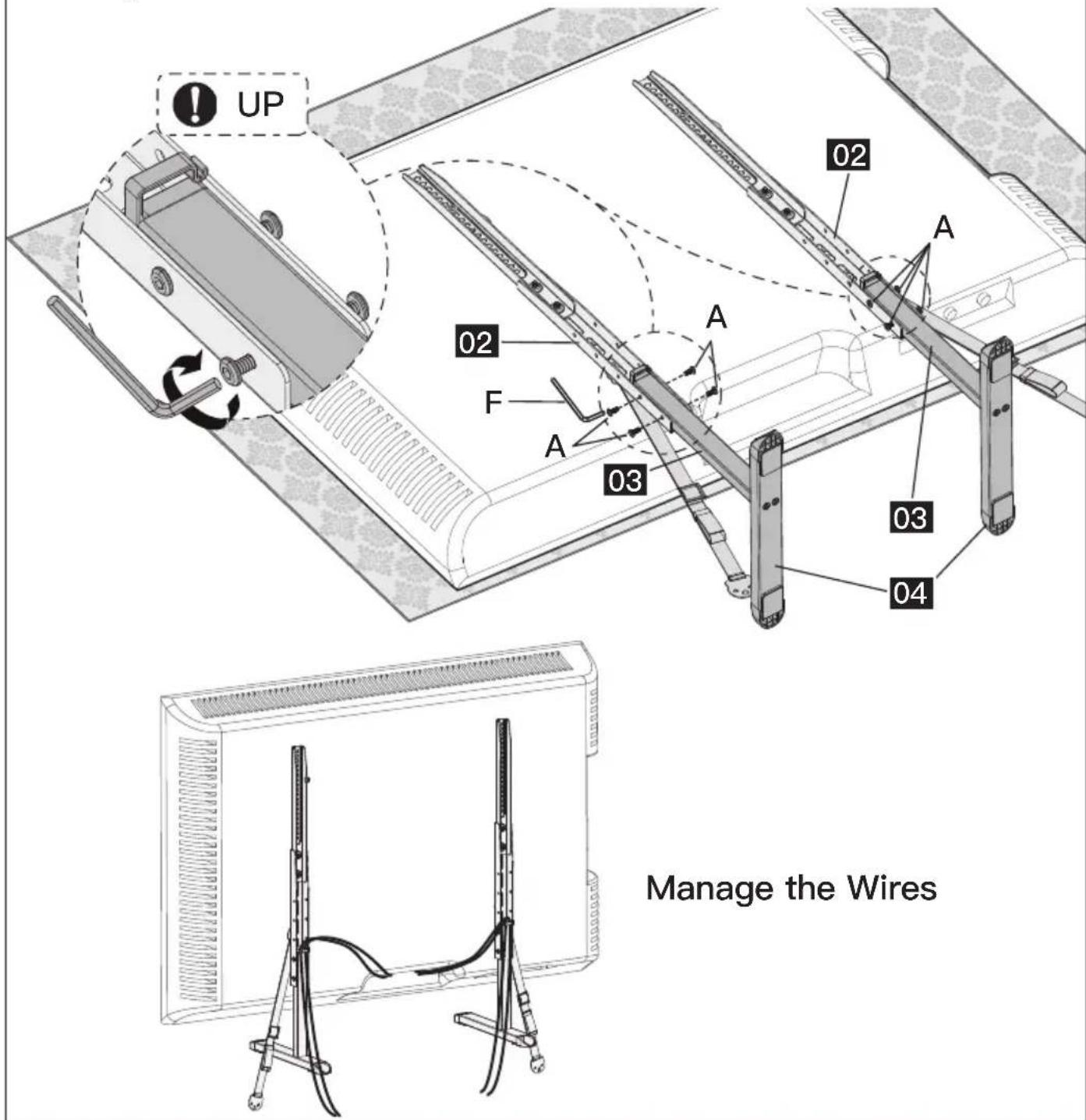
Step 4 Attach Support Pillar [03] to the TV and Manage the Wires
NOTE: Before attaching the support pillar [03] to the TV, measure the distance from the bottom end of the TV Bracket to the bottom of the TV. Then refer to chart below for the recommended mounting location. To add an additional 2" of space between your TV and the base, use the lower hooks located on the TV Brackets. We always recommend using the lowest possible attachment location for the safest assembly.
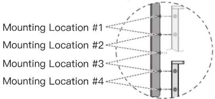
| Distance from the bottom of TV Brackets to the bottom of the TV | Recommended Mounting Location |
| Less Than 0 (TV Bracket is beyond the TV bottom) | Location #1 |
| 0 to 1 1/5” | Location #2 |
| 1 1/5” to 3 1/5” | Location #3 |
| 3 1/5” to 5 1/5” | Location #4 |
- Align the holes of the support pillar with the holes of TV bracket.
- Insert the 4 bolts into the aligned holes.
- Tighten the 4 bolts to secure the support pillar to TV bracket.
WARNING: The 4 bolts can be tightened until they are fully inserted into the holes together.
Supplied Hardware for Step 5A
For wooden table furniture/wood stud installation.
Z1 x2
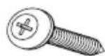
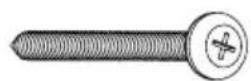
Screw M5X25mm Screw M5X60mm M5 Washer(BK)
Z2 x4
Z3 x2

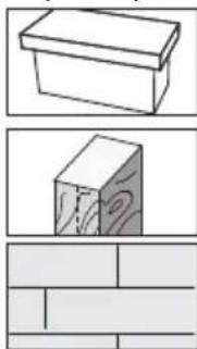
Secure The Safety Straps With TV Stand Against The Wall
NOTE: For the safest possible installation, we recommend using the included safety straps. By doing so, you will greatly reduce the possibility of a TV Tip Over.
natural_image
Three technical diagrams showing 3D and 2D views of a wooden block with no text or symbolsFor wooden table furniture installation, follow STEP 5A
For wood stud installation, follow STEP 5B
For solid concrete or concrete block installation, follow STEP 5C
Step 5A
For Wooden Table furniture Installation
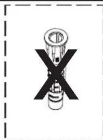
● DO NOT USE ANCHOR [Z4] FOR THIS STEP!
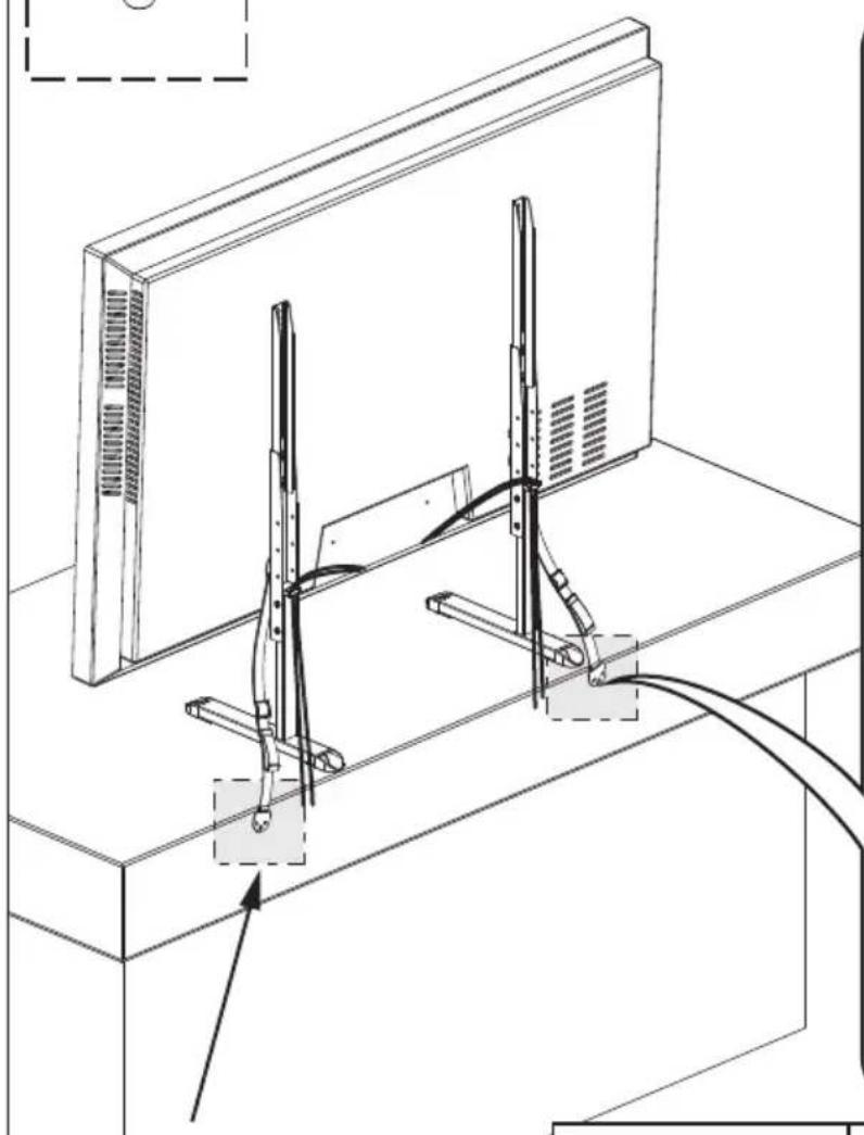
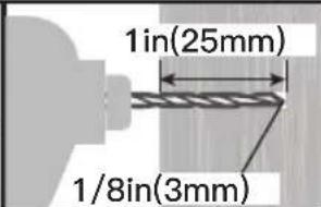
NOTE: It is necessary to predrill a pilot hole to avoid splitting the wood. Being careful not to damage your furniture.
CAUTION: The mounting surface must be thicker than 1in(25mm).
natural_image
Technical line drawing of a computer monitor setup with cable and connectors (no text or symbols)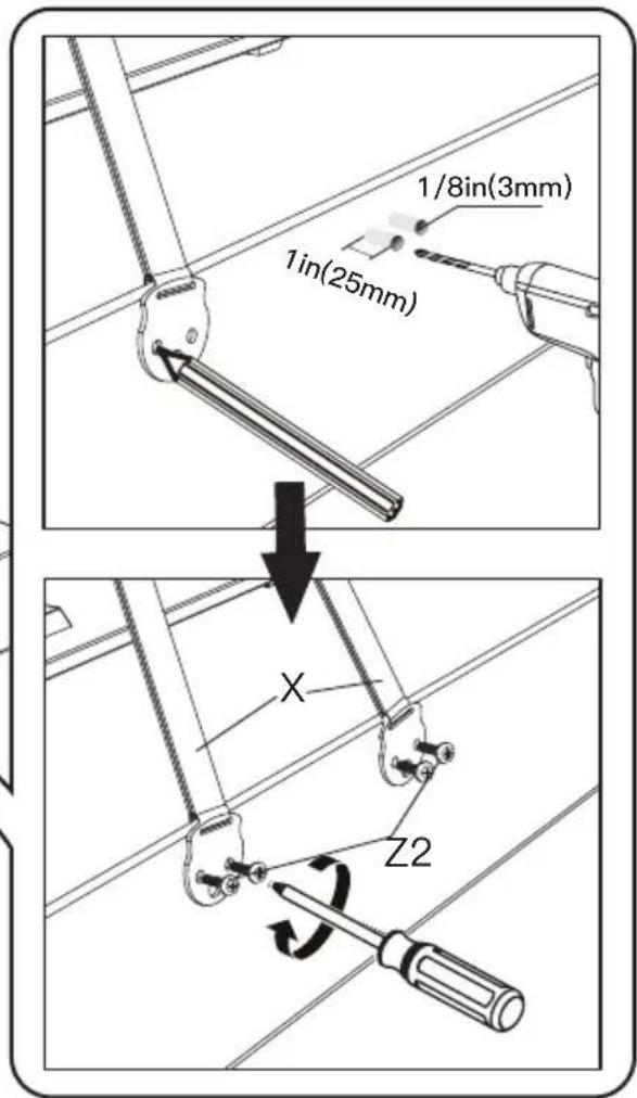
It is recommended that the safety straps be mounted at least 12" apart.
Pencil (Not Included)

Phillips Screwdriver (Not Included)
Step 5B
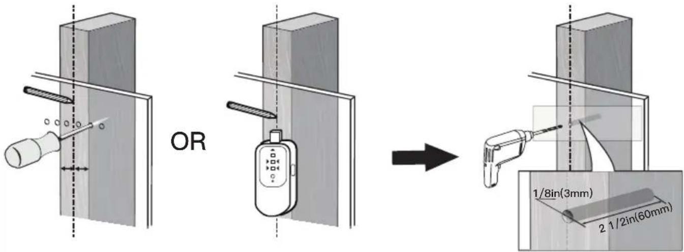
For Wooden Stud Installation

● DO NOT USE ANCHOR [Z4] FOR THIS STEP!
● Any material covering the wall must not exceed 5/8in(16mm)
● Nominal wood stud size: common 2 x 4in(51 x 102mm)
minimum 1½ x 3½in(38 x 89mm).
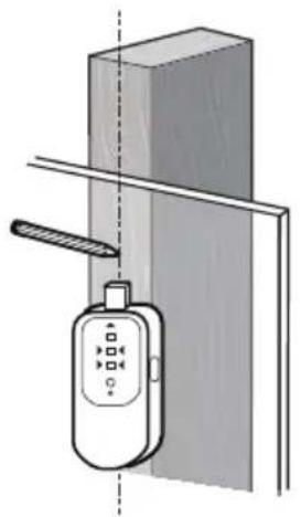
● Stud center must be verified by using an awl or stud finder.

Pencil
(Not Included)
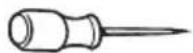
Awl
(Not Included)
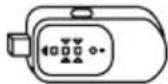
Stud Finder
(Not Included)

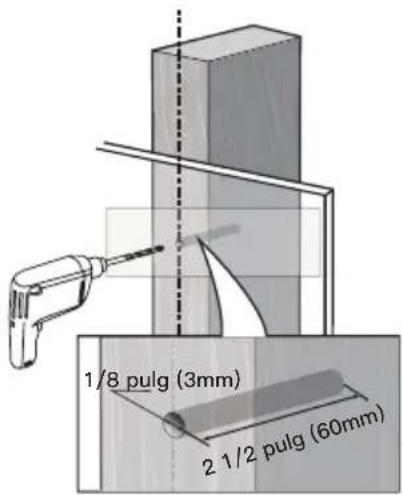
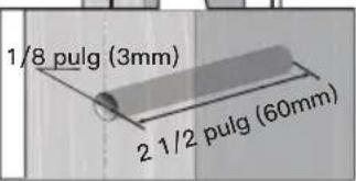
1/8in(3mm)
Wood Drill Bit
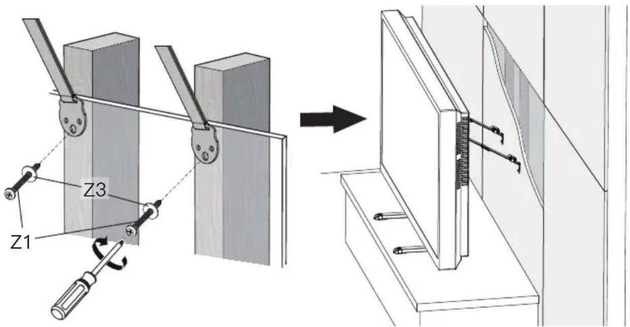
NOTE: Each strap must be mounted to a separate stud.

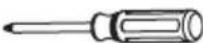
Phillips Screwdriver (Not Included)
Supplied Hardware for Step 5C
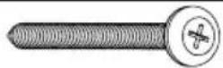
Screw M5X60mm M5 Washer(BK)

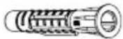
Wall Anchor 8x50mm
Z1 x2
Z3 x2
Z4 x2
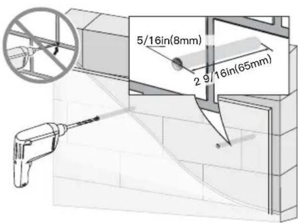
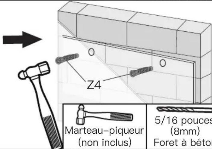
Step 5C For Solid Concrete or Concrete Block Installation
● Must use wall anchor [Z4] for this step.
● Any material covering the wall must not exceed 5/8in(16mm).
● Minimum solid concrete thickness: 203mm(8in).
● Minimum concrete block size: 203 x 203 x 406mm(8 x 8 x 16in).
● Never drill into the mortar between blocks.
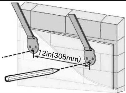

Pencil (Not Included)
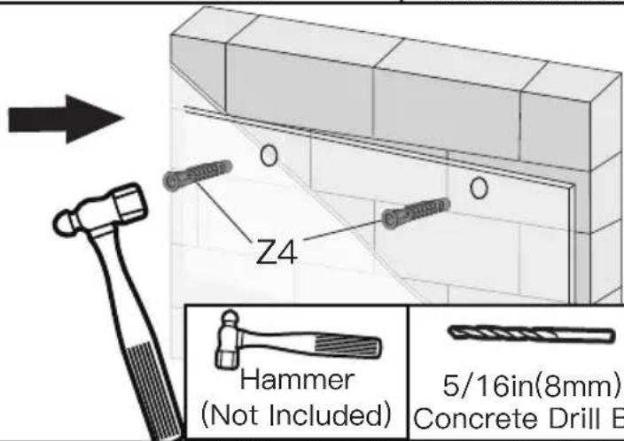

Hammer (Not Included)
5/16in(8mm) Concrete Drill Bit
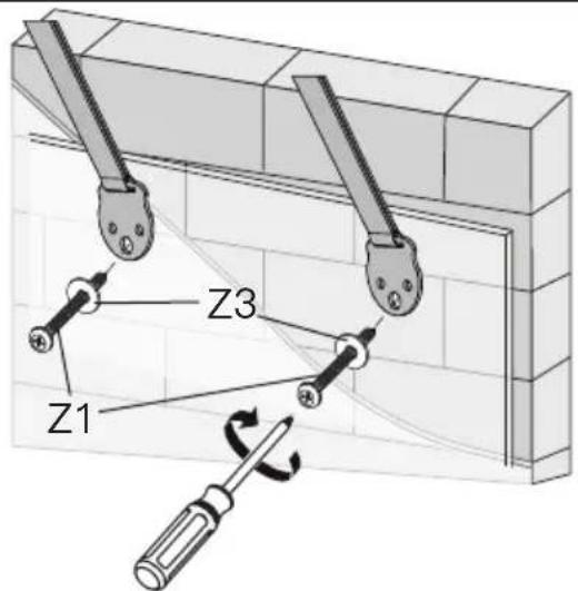
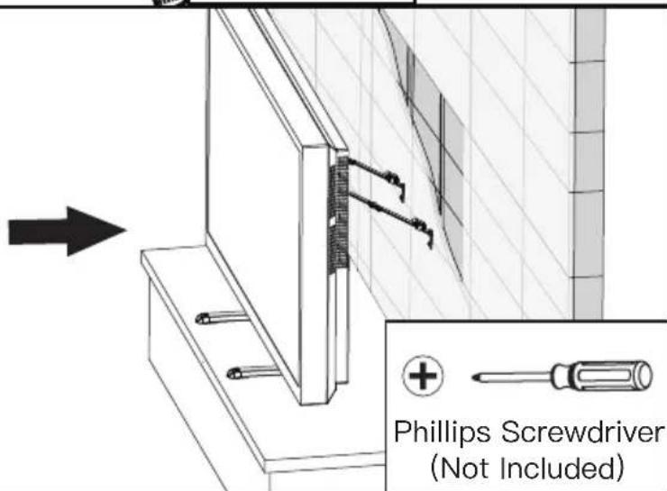

Phillips Screwdriver (Not Included)
(A) x4
M5x12mm boulon
(F) ×1
5/32 pouces (4mm)
Clé hexagonale
natural_image
Technical line drawing of a rectangular metal bracket with mounting holes (no text or symbols)03 x2
Montant du support
natural_image
Technical line drawing of a cylindrical mechanical component with flanges and mounting brackets (no text or symbols)04 x2
Base
(A) x4 M5x12mm boulon
natural_image
Line drawing of a mechanical component with circular holes and a tapered end (no text or symbols)natural_image
Technical line drawing of a rectangular metal bracket with multiple holes and mounting holes (no text or symbols)natural_image
Pure mechanical diagram of a long rod with flanges and central block (no text or symbols)natural_image
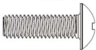
Technical line drawing of a threaded bolt with a flanged end and a circular head (no text or symbols)(C2) x4 M6x35mm Boulon
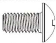
(D1) x4
M8x15mm
Boulon
natural_image
Technical line drawing of a threaded screw with a flat head and a curved tip (no text or symbols)(D2) x4 M8x25mm Boulon
natural_image
Technical line drawing of a threaded bolt with a flanged end and a circular head detail (no text or symbols)(D3) x4 M8x35mm Boulon
natural_image
Technical line drawing of a threaded bolt with a flanged end (no text or symbols)(D4) x4 M8x50mm Boulon
(E1) x8 L2.5mm Entretoise
natural_image
Pure technical line drawing of a cylindrical mechanical component with no text or symbols(E2) x4 L10mm Entretoise

natural_image
Pure technical line drawing of a cylindrical mechanical part with no text or symbols(E3) x4 L22mm Entretoise
natural_image
Line drawing of a hand pressing down on a device casing with a circular arrow indicating rotation (no text or symbols)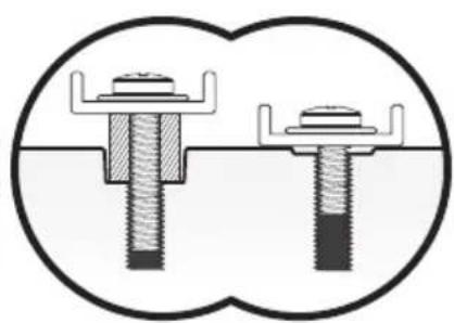
natural_image
Diagram of two screw fasteners in a holder, showing different mounting configurations (no text or labels)
Trop court Correct Trop long
Option C (For TV with A "Bump")
(A) x4 M5x12mm boulon
(F) x1 5/32 pouces (4mm) Clé hexagonale
natural_image
Diagram showing light rays reflecting off a wall and adjacent to a door, enclosed in a dashed circle (no text or symbols)natural_image
Three-panel diagram showing 3D block arrangements: top is a flat rectangular block, middle is a wooden block with visible grain texture, bottom is a blank grid (no text or symbols)L'ANCRE N'EST PAS UTILISÉE [Z4] DANS CETTE ÉTAPE!

Tournevis Phillips (non inclus)
(A) x4 M5x12mm Perno
(F) x1
5/32 pulg (4mm)
Llave Allen
natural_image
Technical line drawing of a rectangular metal bracket with mounting holes (no text or symbols)03 x2
Pilar de soporte
natural_image
Technical line drawing of a cylindrical mechanical component with flanges and internal brackets (no text or symbols)04 x2
Base
natural_image
Line drawing of a mechanical component with circular holes and a tapered end (no text or symbols)natural_image
Technical line drawing of a rectangular metal bracket with multiple holes and mounting holes (no text or symbols)natural_image
Pure mechanical diagram of a long rod with flanges and central block (no text or symbols)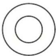
(B) x4 M6/M8 Arandela
natural_image
Technical line drawing of a threaded screw with a flat head and a curved tip (no text or symbols)(C2) x4 M6x35mm Perno
(D1) x4
M8x15mm
Perno

natural_image
Technical line drawing of a threaded screw with a flat head and a curved tip (no text or symbols)(D2) x4 M8x25mm Perno
natural_image
Technical line drawing of a threaded bolt with a flanged end and a circular hole (no text or symbols)(D3) x4 M8x35mm Perno
natural_image
Technical line drawing of a threaded bolt with a flanged end (no text or symbols)(D4) x4 M8x50mm Perno
natural_image
Pure technical line drawing of a cylindrical mechanical component with no text or symbols(E2) x4
L10mm
Espaciador
natural_image
Simple line drawing of a cylindrical mechanical component with concentric rings and mounting holes (no text or symbols)natural_image
Two types of threaded fasteners shown side by side, one with a flat head and the other with a flat top, both without any text or symbols.M6 M8
natural_image
Line drawing of a computer monitor with a hand holding a scroll wheel (no text or symbols)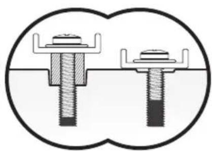
natural_image
Diagram of two dental implants in a toothed joint, showing different mechanical configurations (no text or labels)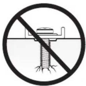
(A) x4 M5x12mm Perno
(F) x1 5/32 pulg (4mm) Llave Allen
natural_image
Diagram showing light rays reflecting off a wall, with no text or symbols presentnatural_image
Three technical diagrams showing a wooden block, a brick block, and a brick wall (no text or symbols)● NO UTILICE EL ANCLA [Z4] EN ESTE PASO!
natural_image
Diagram of a mechanical assembly with a tool and screwdriver inserted into a rectangular block (no text or symbols)O
natural_image
Diagram of a mobile phone mounted on a door panel, showing hand positioning and no text or symbols
natural_image
Technical line drawing of a mechanical assembly with a bracket and pin inserted (no text or symbols)
natural_image
Architectural line drawing of a window with diagonal grid lines and a shaded rectangular area (no text or symbols)
At ErgoAV, we strive to provide the highest valued products.
We want to support your purchase.
If you have questions, concerns,
or feedback please let us know!
ErgoAV Customer Care
Phone (877) 419-7832 M-F 8am to 8pm CST
support@ergoav.com
natural_image
Technical line drawing of a mechanical assembly with no visible text or symbolsTV Mounts
natural_image
Simple line drawing of a vertical cylindrical object with base and wheels (no text or symbols)Speaker Stands
natural_image
Technical line drawing of a Y-shaped mechanical assembly with two arms and a central shaft (no text or symbols)Computer Monitor Mounts

- Table Top TV Stand Instruction Manual
- IMPORTANT SAFETY INFORMATION
- Before getting starting, let's make sure this mount is perfect for you!
- Tools Needed (Not Included)
- Supplied Parts and Hardware
- Supplied Parts and Hardware for Step 1
- Step 3 Secure the TV Brackets [N] and the Safety Straps [P] to TV
- Select TV Bolts
- Option A (For Flat Back TV)
- Option C (For TV with A "Bump")
- Option D (for TV with Cable Interference)
- Option E (For Recessed Holes)
- Supplied Part and Hardware for Step 4
- Step 4 Attach Support Pillar [03] to the TV and Manage the Wires
- Supplied Hardware for Step 5A
- Secure The Safety Straps With TV Stand Against The Wall
- Step 5A
- For Wooden Table furniture Installation
- Step 5B
- For Wooden Stud Installation
- Supplied Hardware for Step 5C
- Step 5C For Solid Concrete or Concrete Block Installation
Brand : ErgoAV
Model : ERTSX1-01B
Category : TV Stand