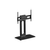
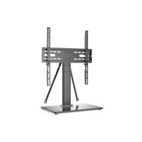
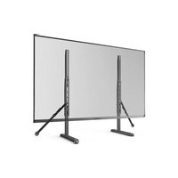
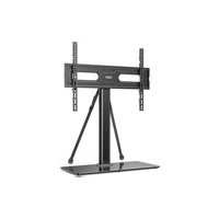
ERTSX2-01B - TV Stand ErgoAV - Free user manual and instructions
Find the device manual for free ERTSX2-01B ErgoAV in PDF.


| Product type | TV stand with optional wall mount |
| Brand | ErgoAV |
| Model | ERTSX2-01B |
| VESA compatibility | 200×100, 200×200, 200×300, 200×400, 300×200, 300×300, 400×200, 400×300, 400×400, 600×400 mm (max) |
| Maximum screen size | Up to 600 × 400 mm (23.6 × 15.7 in) |
| Height adjustable | Yes (3 positions) |
| Rotation | Swivel left/right |
| Wall mountable | Yes (wood stud, concrete or concrete block) |
| Safety straps included | Yes (2 straps) |
| Cable management | Yes (cable entry and exit with back cover) |
| Materials | Steel, plastic |
| Included accessories | Bolts and screws (M4, M6, M8), spacers, washers, Allen keys, drilling template |
| Tools required (not included) | Electric drill, pencil, Phillips screwdriver, tape measure |
| Cleaning and maintenance | Wipe with a soft, dry cloth |
Frequently Asked Questions - ERTSX2-01B ErgoAV
User questions about ERTSX2-01B ErgoAV
0 question about this device. Answer the ones you know or ask your own.
Ask a new question about this device
Download the instructions for your TV Stand in PDF format for free! Find your manual ERTSX2-01B - ErgoAV and take your electronic device back in hand. On this page are published all the documents necessary for the use of your device. ERTSX2-01B by ErgoAV.
USER MANUAL ERTSX2-01B ErgoAV
natural_image
Technical line drawing of a mechanical device with vertical supports and a central oval component (no text or symbols)ERTSX2
Thank You for Choosing ErgoAV!
At ErgoAV, our goal is to add value to your AV experience by providing the highest quality products and services in the industry. If you have any questions or concerns, please contact us.
BEFORE GETTING STARTED, LET'S MAKE SURE THIS STAND IS COMPATIBLE
1
Check VESA
Pattern
Compatibility
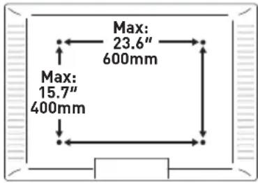
Compatible VESA Patterns:
200 x 100mm 200 x 400mm 400 x 200mm
200 x 200mm 300 x 200mm 400 x 300mm
200 x 300mm 300 x 300mm 400 x 400mm
Maximum/Minimum:
600 x 400mm (23.6 x 15.7") 600 x 400mm
200 x 100mm (7.9 x 3.9")
If this stand is not compatible, please contact product support.
2
Check Max
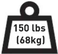
Load

WARNING
DO NOT exceed the Max Load. Use with products heavier than the Max Load may result in failure of the mount and its accessories, causing possible damage and or injury.
If your TV weighs more, this stand is NOT compatible.
3
Verify Wall Type
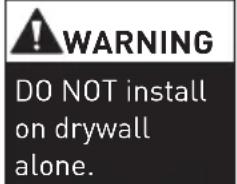
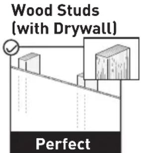
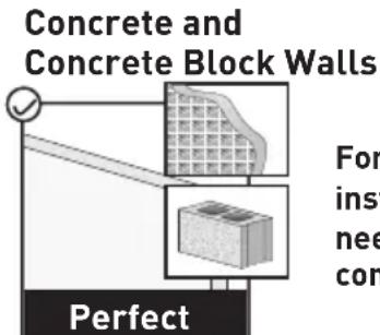
For safety strap installations, you will need to verify your wall construction.
4
Tools Needed (not included)
Electric Drill
Pencil
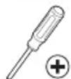
Phillips
Screwdriver
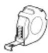
Tape Measure
For safety bolt installation
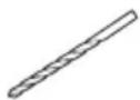
5/16" (8mm)
Wood Drill Bit
For safety strap installation into wood


1/8" (3mm)
Wood Drill BitSt
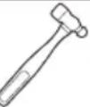
ud FinblamAmer
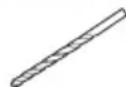
5/16" (8mm)
Concrete Drill Bit
5
Important Safety Information
⚠️ DANGER: Please carefully read all instructions before attempting installation. If you DO NOT understand the instructions or have any questions or concerns, please call technical support or email customer service.
CAUTION: Avoid the risk of personal injury and property damage!
⚠ WARNING: All fasteners must be firmly tightened!
- This product contains small parts that may pose a choking hazard.
- DO NOT use this product for any purpose that is NOT explicitly specified in this manual. DO NOT exceed the maximum weight capacity. We are not liable for damage or injury caused by incorrect assembly, improper mounting, or inappropriate use.
- Use this mounting system only for its intended purpose as described in these instructions. DO NOT use attachments not recommended by the manufacturer.
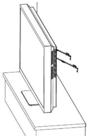
▲ TIP-OVER WARNING: Serious or fatal crushing injuries can occur from a tip-over accident.
To help prevent a tip-over accident:
- Never allow children to climb, stand, hang, or play on any part of the TV or TV stand.
- Use tip-over restraints or anchors to attach the TV stand to the wall.
- Use of tip-over restraints may only reduce, but not eliminate risk of a tip-over accident.
SAVE THESE INSTRUCTIONS
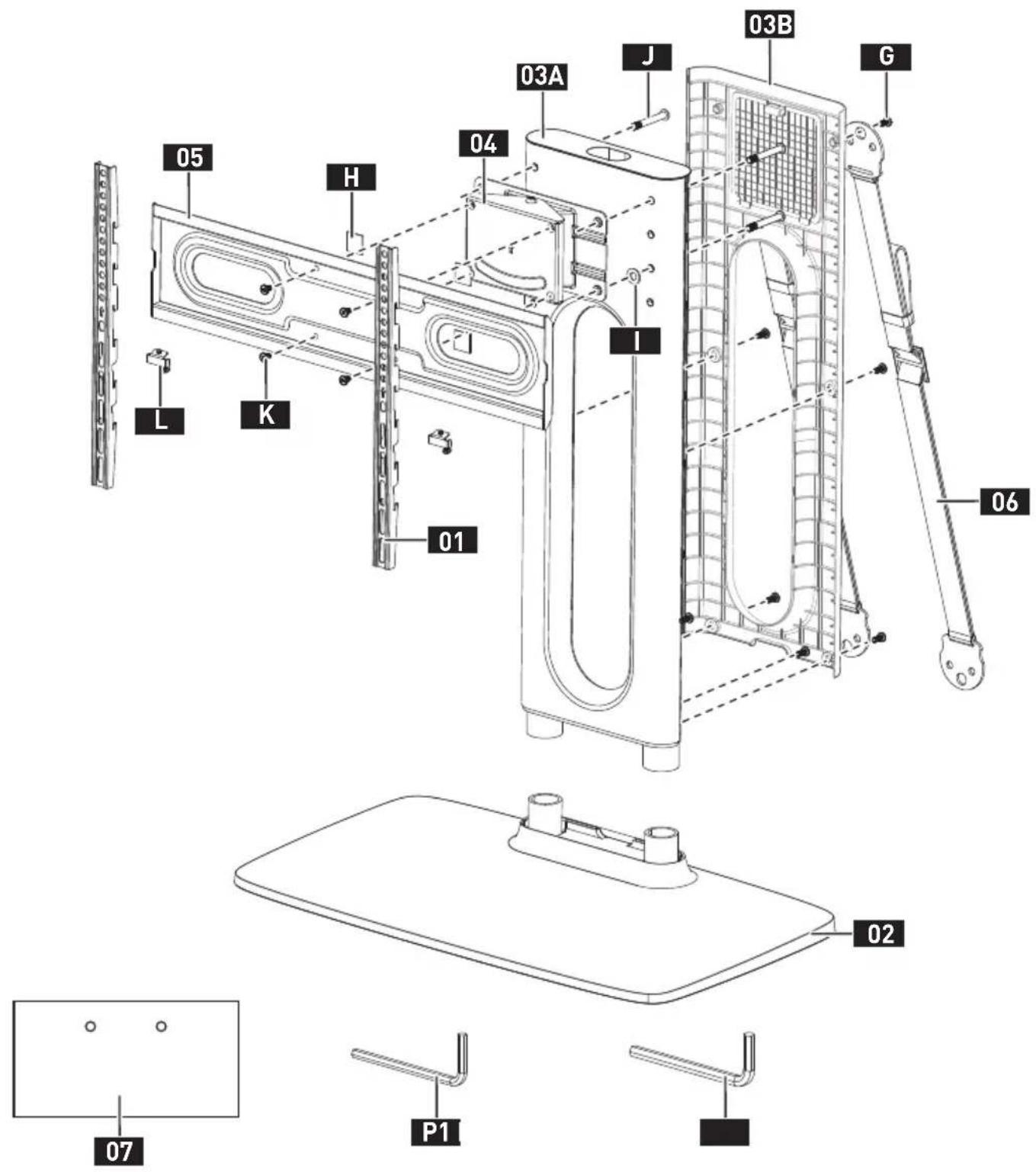
01 TV Bracket
02 Base
03A Support Pillar
03B Back Cover
04 Swivel Bracket
05 TV Plate
06 Safety Strap
07 Drill Template
G Bolt
H EVA Pad
Steel Washer
J Bolt
K Bolt
L Safety Lock
P1 Small Allen Key
P2 Large Allen Key
Supplied Parts and Hardware for Step 1
Not all hardware included in this package will be used.

natural_image
Technical line drawing of a mechanical component with multiple slots and end caps (no text or symbols)TV Bracket
01×2
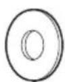
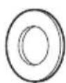
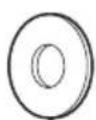
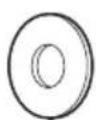
M4/M5
Washer
B1×4
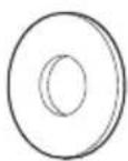
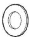
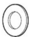
M6/M8
Washer
B2 x 4
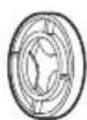
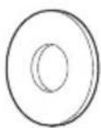
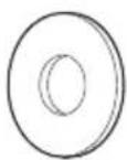
D8
Washer
B3×4
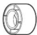
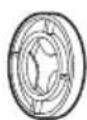
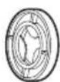
L2.5mm
Spacer
F1 x 8
L10mm
Spacer
F2×4
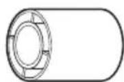
L22mm
Spacer
F3×4
M4
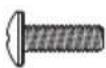
M4 x 12mm
TV Bolt
C1×4
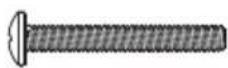
M4 x 30mm
TV Bolt
C2×4
M6
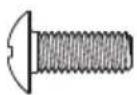
M6 x 15mm
TV Bolt
D1×4
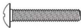
M6 x 35mm
TV Bolt
D2×4
M8
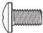
M8 x 15mm
TV Bolt
E1 x 4
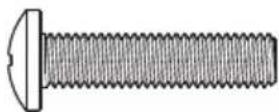
M8 x 35mm
TV Bolt
E2×4
natural_image
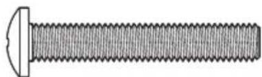
Technical illustration of a bolt with threaded shaft and flange (no text or symbols)M8 x 50mm
TV Bolt
E3 x 4
STEP 1 Attach the TV Brackets to Your TV
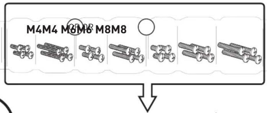
1-1 Select TV Bolts
The correct bolt diameter will thread smoothly into your TV.
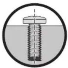
natural_image
Cross-sectional diagram of a bolt with threaded shaft and cap, enclosed in a circle (no text or symbols)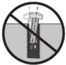
that fit (M4, M6, or M8)
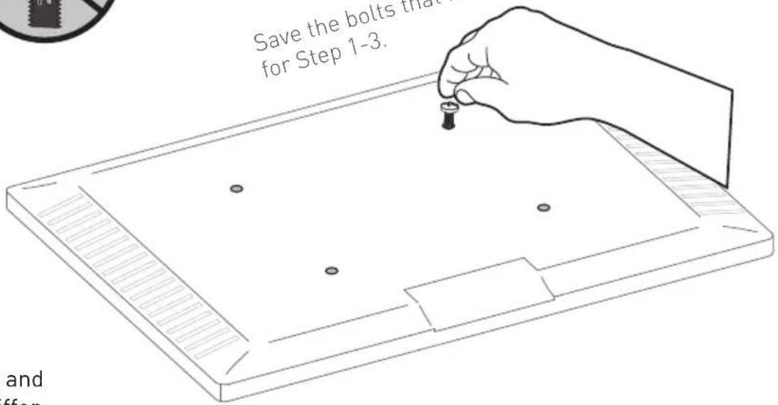

The depth of the top and bottom holes may differ.
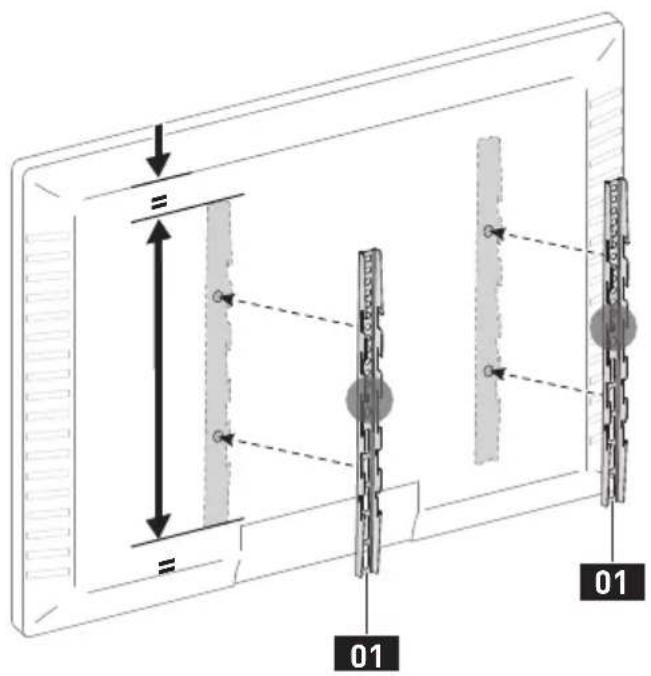
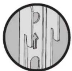
1-2 Position the TV Brackets
natural_image
Circular diagram showing abstract line patterns with no text or symbolsArrow Up

natural_image
Pure electrical circuit lines without any symbols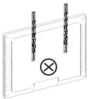
natural_image
Pure electrical circuit lines without any symbols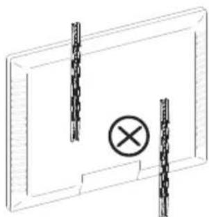
natural_image
Pure electrical circuit lines without any symbols1-3 Secure the TV Brackets
For Flat-Back TV, go to Option A on this page.
For Bump, Curved TV, Recessed Holes and Cables, go to Option B on next page.

WARNING:
- DO NOT turn the bolt past the bottom of the hole.
- If the bolt is too short, it may not adequately support the TV.
- If the bolt is too long, it could damage the TV.
- At least 4–5 turns into the threading is required.
- The depth of the bottom holes may be different from the top holes.
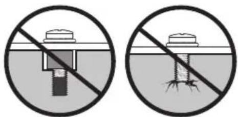
natural_image
Two circular diagrams showing a screw with a central dot and a base, separated by a diagonal line (no text or symbols)Too Short Too Long
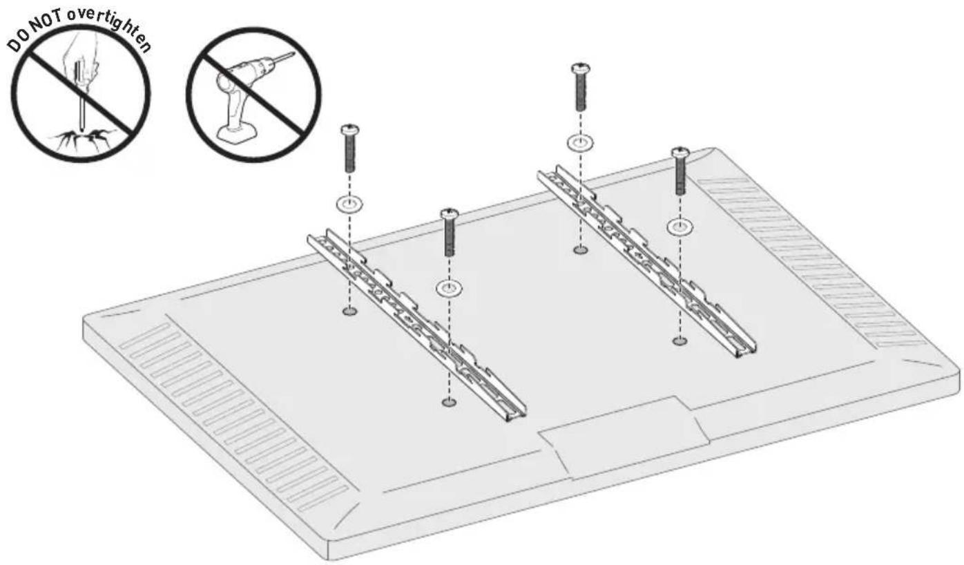
Option A
Use short TV bolts with washers.

Flat-Back TV

natural_image
Pure diagram of a mechanical component with no text, numbers, or symbols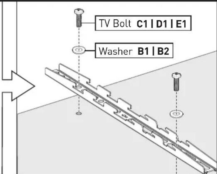
Option B
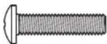
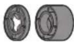
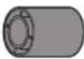
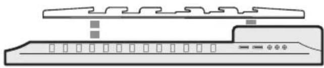
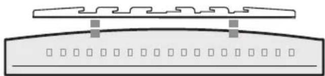
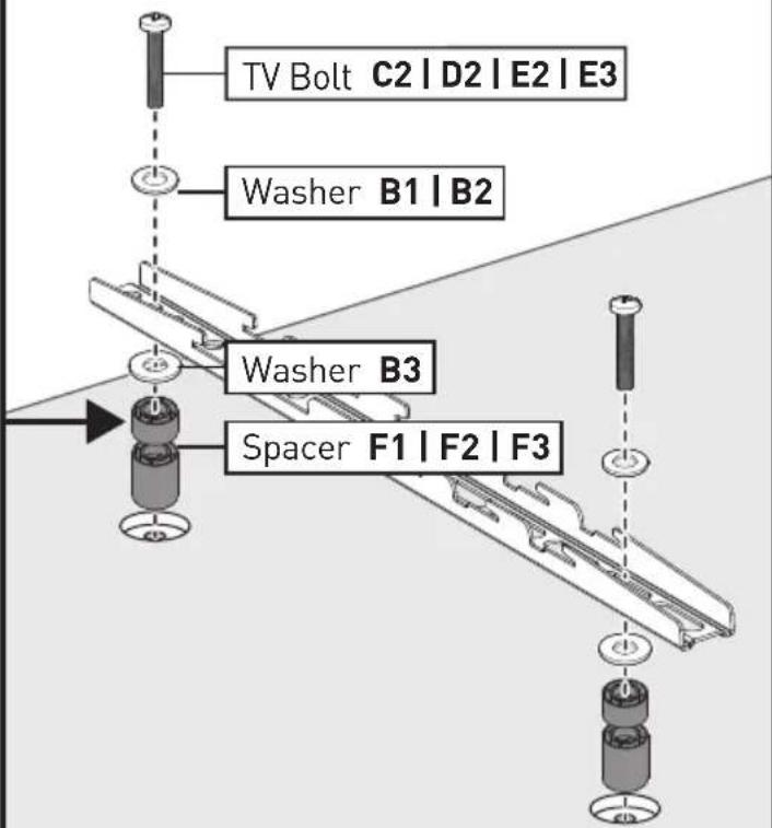
Use long TV bolts with washers and spacers to create extra space between the TV and brackets.

Bump
natural_image
Diagram of a device with two components, one above and one below, showing internal structure and control buttons (no text or symbols)Curved TV
natural_image
Pure diagram of a mechanical or architectural component with no text, numbers, or symbolsTV with Mounting Restrictions
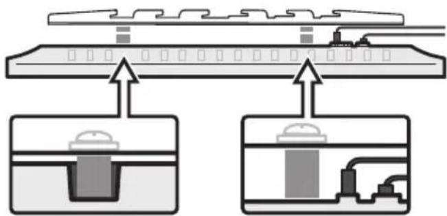
Recessed Holes Protruding Cables
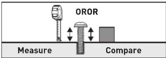
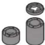
You can use a tape measure to measure the protruding bolts or hold spacers next to them to choose the right spacer combination.
Note:
There are many possible spacer combinations that can be used.


(877) 419-7832
Mon-Fri 8am - 8pm (CST)

support@ergoav.com
Supplied Parts and Hardware for Step 2
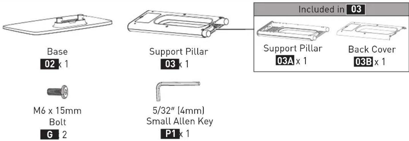
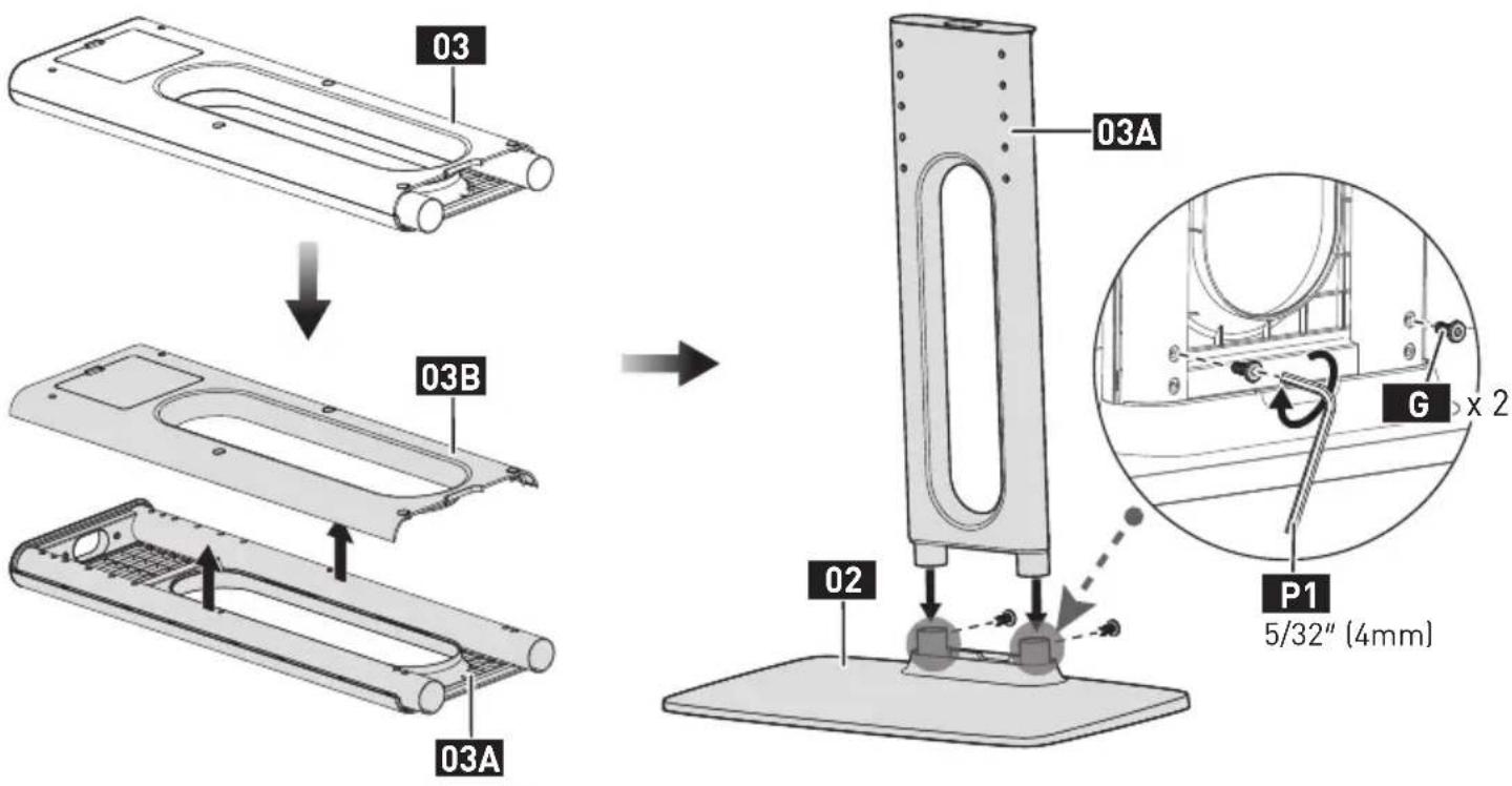
STEP 2 Connect the Support Pillar to the Base
Supplied Parts and Hardware for Step 3
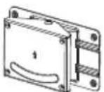
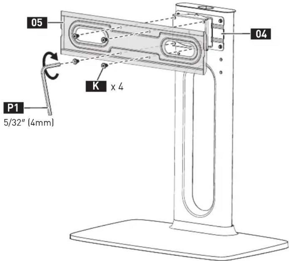
Swivel Bracket
04 x 1
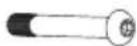
M8 x 60mm
Bolt
J4
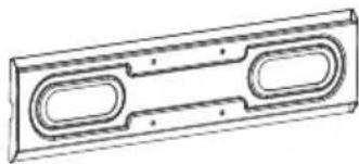
natural_image
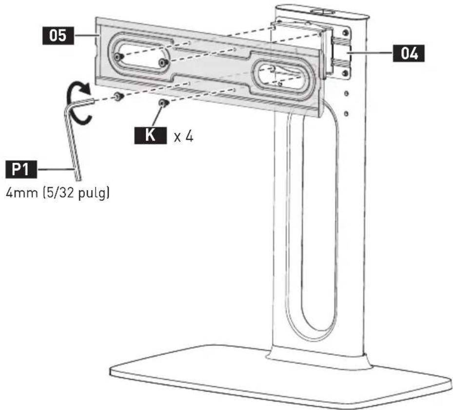
Technical line drawing of a rectangular mechanical part with two oval cutouts (no text or symbols)TV Plate
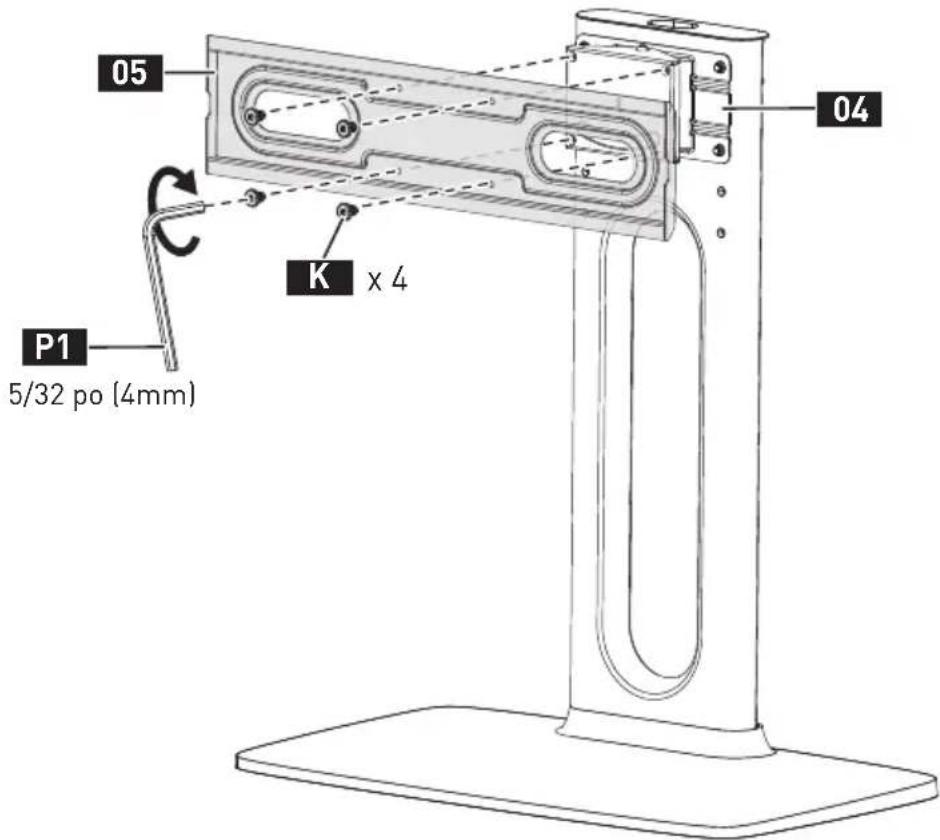
05×1

M6 x 10mm
Bolt
K 4
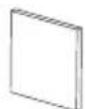
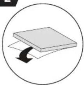
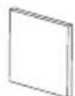
EVA Pad
H 4
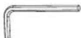
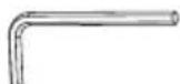
5/32" (4mm)
Small Allen Key
P1 x 1

8.5 × 20 × 2mm Steel Washer
12
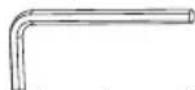
3/16" (5mm)
Large Allen Key
P2 x 1
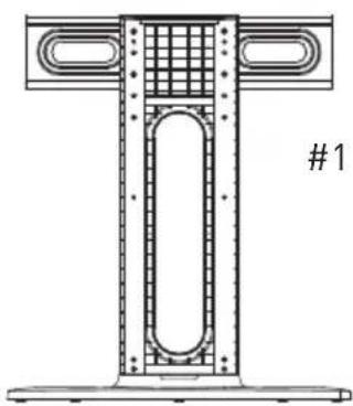
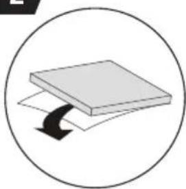
STEP 3 Secure the TV Plate to the Support Pillar
1
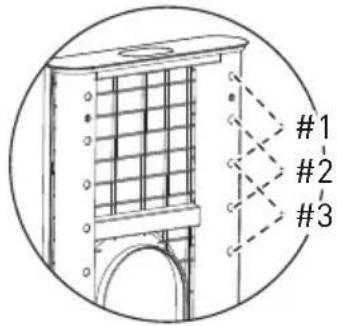
3 Height Options
natural_image
Technical line drawing of a T-shaped structural component with internal grid and flanged ends (no text or symbols)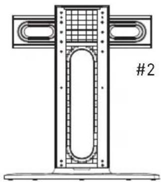
natural_image
Technical line drawing of a T-shaped structural component with internal grid and flanged ends (no text or symbols)
natural_image
Technical line drawing of a mechanical component with grid and oval features (no text or symbols)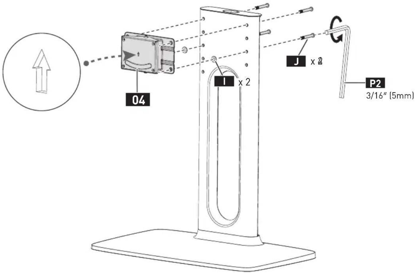
2
natural_image
Simple diagram of a rectangular block with a curved arrow indicating rotation or force, enclosed in a circle (no text or symbols)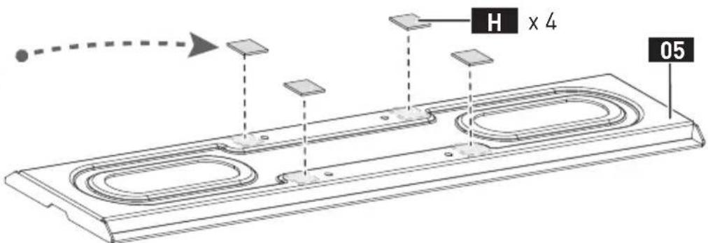
Supplied Parts and Hardware for Step 4
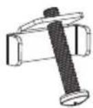
Safety Lock
L 2
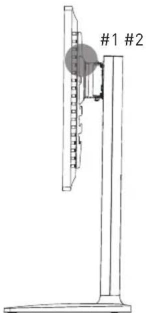
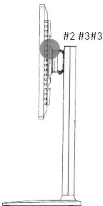
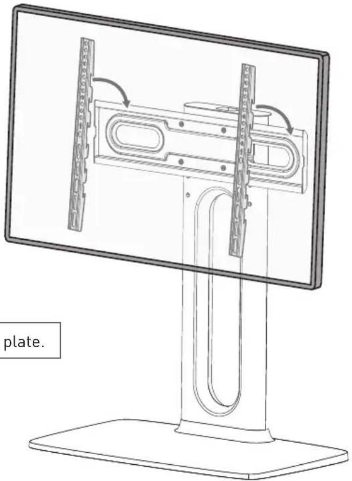
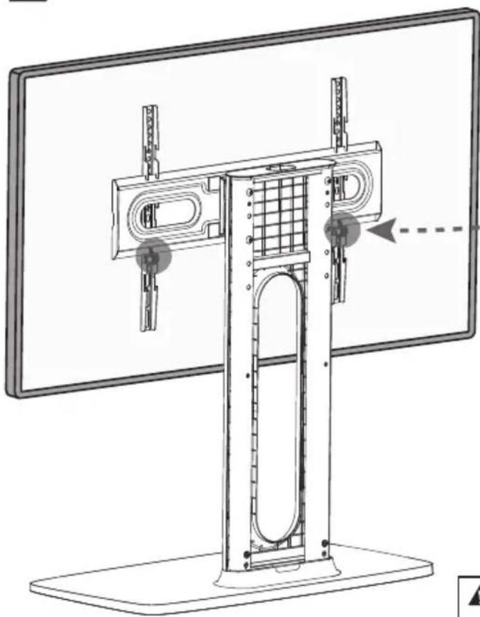
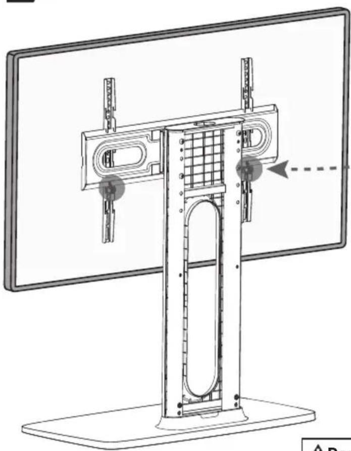
STEP 4 Hang the TV on the TV Plate
1
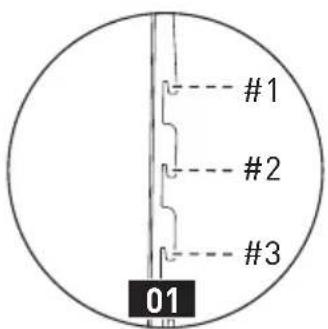
3 Height Options

natural_image
Technical line drawing of a mechanical support structure with a circular component (no text or symbols)2


HEAVY! You may need assistance with this step.
▲Note: Hang the TV on the center of the TV plate.
3
natural_image
Technical line drawing of a mechanical device mounted on a monitor, showing structural components and alignment (no text or symbols)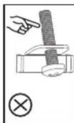
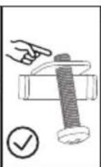
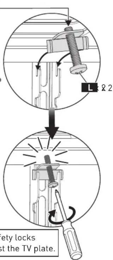
▲Note: Tighten the safety locks until they secure against the TV plate.
Supplied Parts and Hardware for Step 5

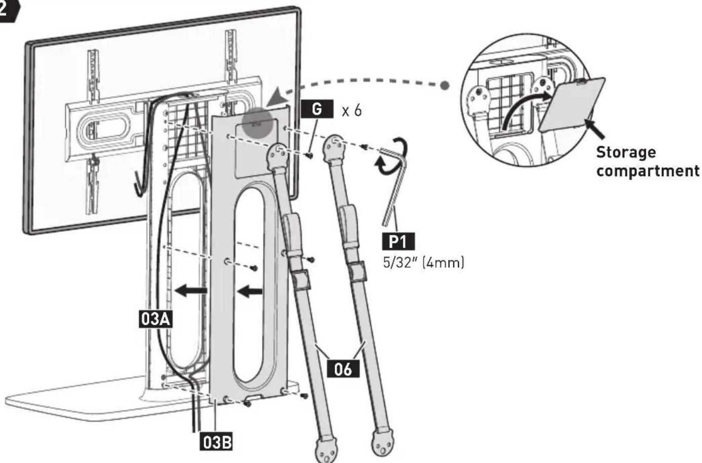
Safety Strap
06 k 2

M6 x 15mm
Bolt
G 6
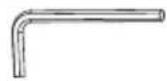
5/32" (4mm)
Small Allen Key
P1 x 1
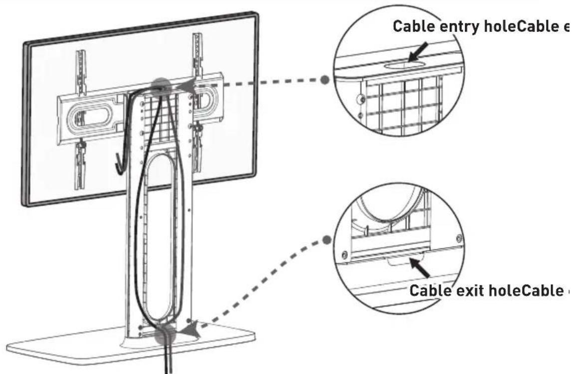
STEP 5 Manage the Cables and Attach the Back Cover
1
2
Supplied Parts and Hardware for Step 6
natural_image
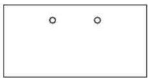
Simple diagram with two small circles inside a rectangle (no text or symbols)Drill Template
07 x 1
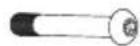
M6 x 50mm
Bolt
M×2

Φ6.5×16×2mm
Steel Washer
N:2 x1
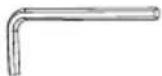
5/32" (4mm)
Small Allen Key

STEP 6 Secure the Base to the Wooden Table Furniture (Optional)
1
▲Note: Be sure to use the specified drill bit.
CAUTION: The mounting surface must be 0.6"-0.8" (15-20mm) thick. If the mounting surface exceeds this range, please do not follow this step.
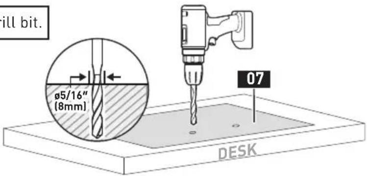
2


HEAVY! You may need assistance with this step.
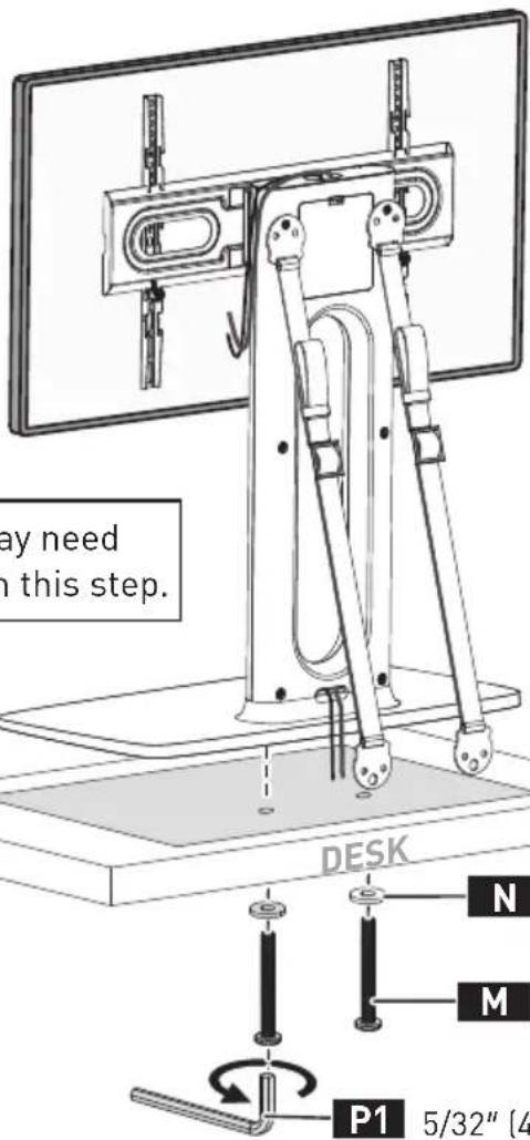
P1
5/32" (4mm)
Supplied Parts and Hardware for Step 7
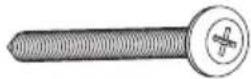
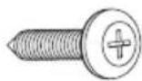
M5 x 60mm Screw
Z1 × 2
M5 x 25mm Screw
Z2×4
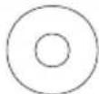
M5 Washer (BK)
Z3 × 2
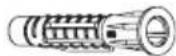
Wall Anchor
24×2
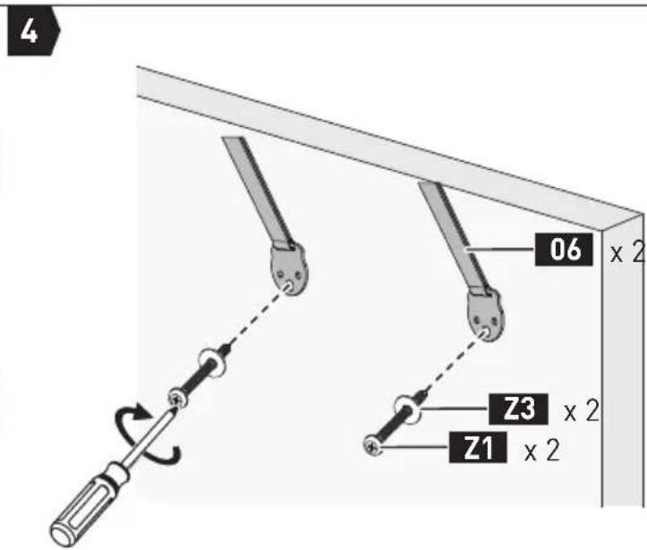
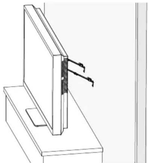
STEP 7 Secure the TV Stand against the Furniture or Wall
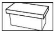
For wooden table furniture installation, follow Option A on page 14.
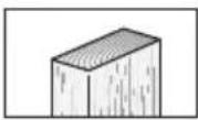
For wood stud installation, follow Option B on page 15.
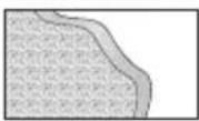
For concrete and concrete block wall installation, follow Option C on page 16.
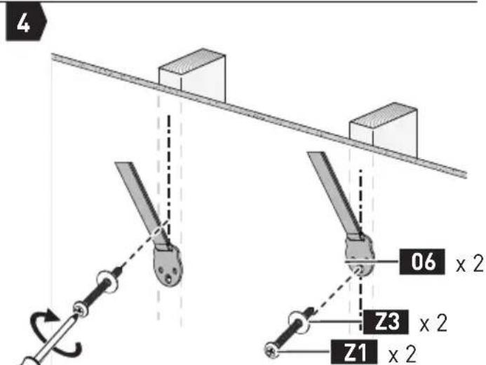
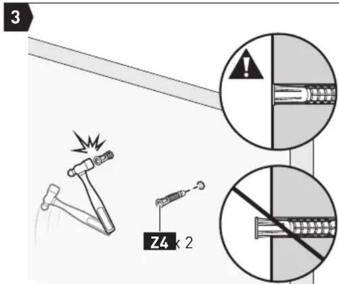
Option A: For Wooden Table Furniture Installation
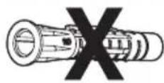
• DO NOT USE ANCHOR Z4 FOR THIS STEP!
Note: It is necessary to predrill a pilot hole to avoid splitting the wood. Be careful not to damage your furniture.
⚠️CAUTION: The mounting surface must be thicker than 1" (25mm). If your mounting surface is less than 1" (25mm), please follow Option B or C to mount safety straps to wall.
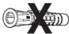
Z4
Wall Anchor
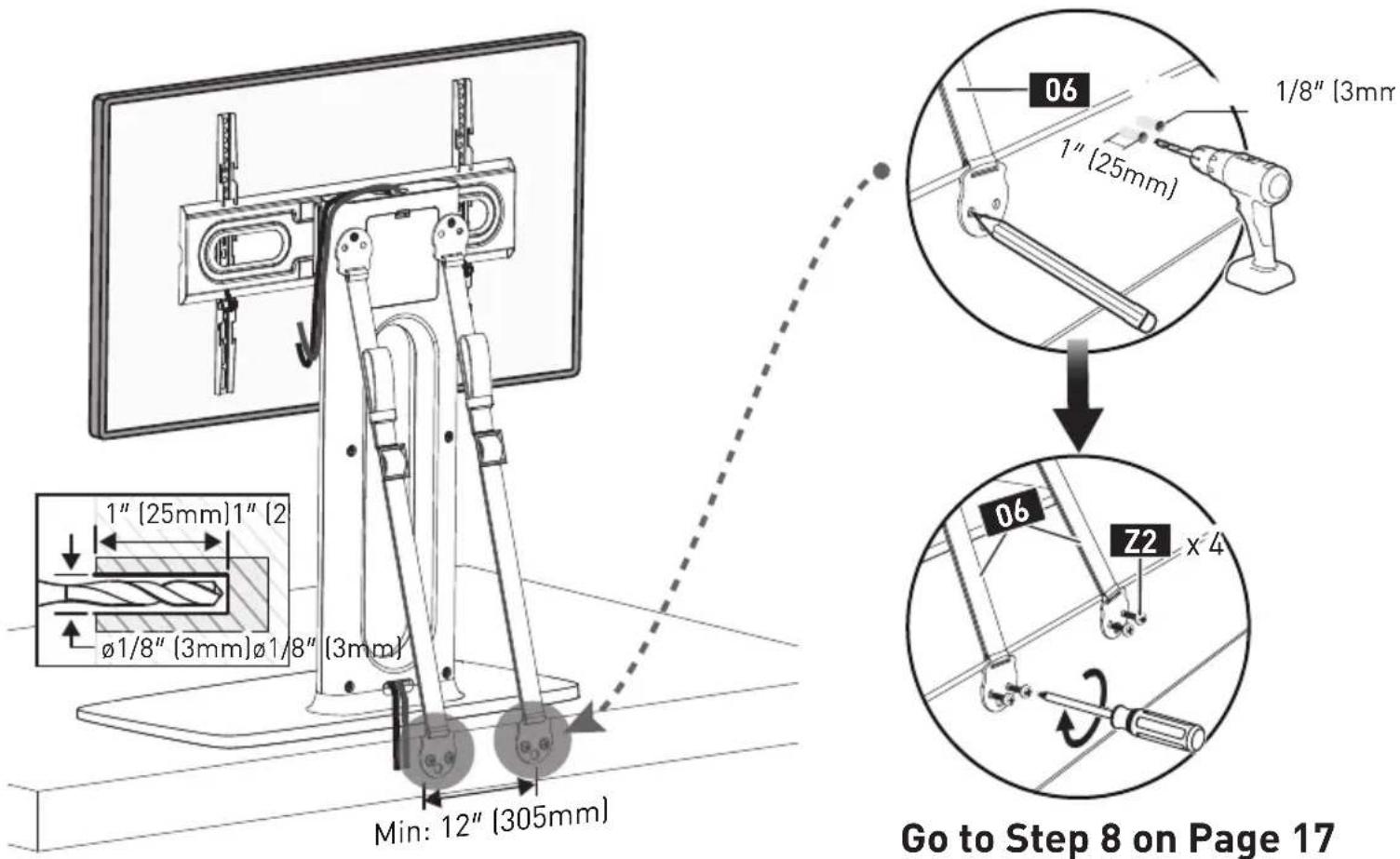
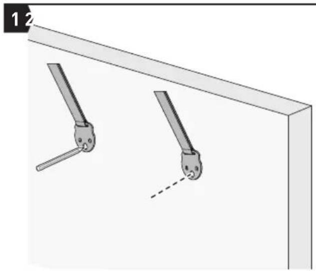
Option B: For Wood Stud Installation
• DO NOT USE ANCHOR Z4 FOR THIS STEP!
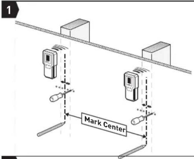
- Any material covering the wall must not exceed 5/8" (16mm).
- Nominal wood stud size: common 2 x 4" (51 x 102mm) minimum 1 12 × 3 12 [38 x 89mm]
- Stud center must be verified by using an awl or stud finder.
24
Wall Anchor
natural_image
Diagram showing two mechanical clamping setups with lever arms and blocks, no text or symbols present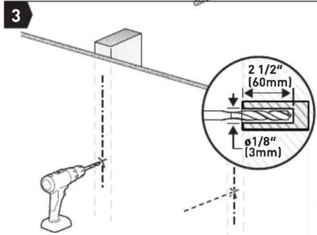
▲Note: Be sure to use the specified drill bit.
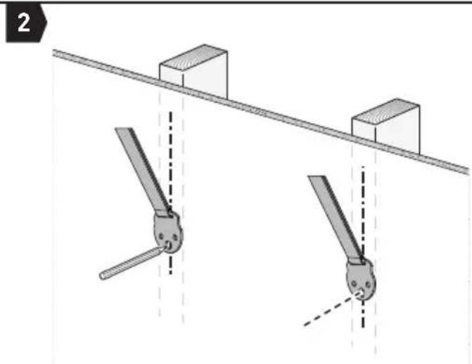
Note: Each strap must be mounted to a separate stud.
natural_image
Technical line drawing of a mechanical assembly with a bracket and mounting base (no text or symbols)
Go to Step 8 on Page 17
Option C: For Concrete and Concrete Block Wall Installation
- Must use wall anchor Z4 for this step.
- Any material covering the wall must not exceed 5/8" (16mm).
• Minimum solid concrete thickness: 8" (203mm) - Minimum concrete block size: 8 x 8 x 16" (203 x 203 x 406mm)
natural_image
Diagram of two mechanical clamps hanging from a beam, with no text or symbols present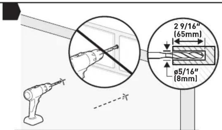
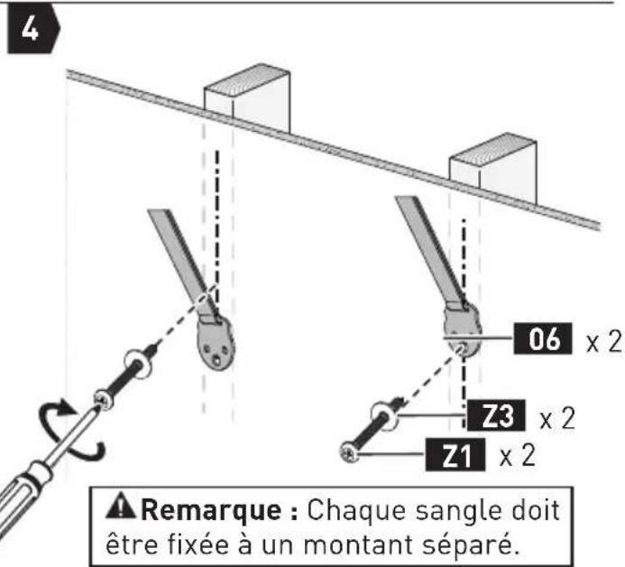
Note:
- Be sure to use the specified drill bit.
- Never drill into the mortar between blocks.
natural_image
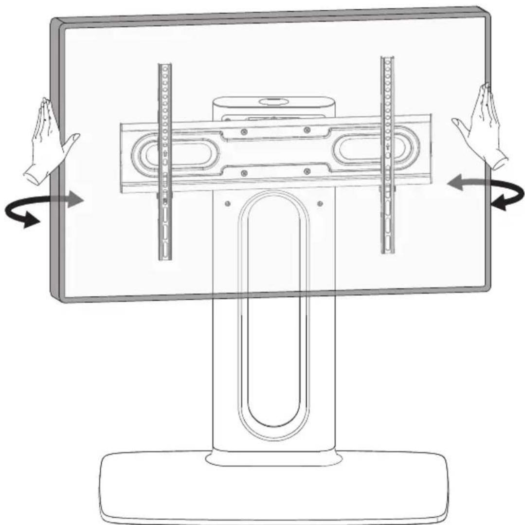
Technical line drawing of a structural joint or bracket assembly (no text or symbols)STEP 8 Swivel Adjustment
The TV can be swivelled left or right. Only swivel the TV by the TV edges. Do not press on the screen.
natural_image
Diagram of a computer monitor with directional arrows indicating rotation or movement (no text or symbols present)AVANT DE COMMENCER, ASSUREZ-VOUS QUE CE SUPPORT EST COMPATIBLE
1
natural_image
Simple line drawing of a container with two blocks and a checkmark, no text or symbols presentParfait
Parfait
01 Support TV
02 Base
natural_image
Technical line drawing of a mechanical component with multiple circular features and segmented sections (no text or symbols)Support TV
01×2
M4/M5
Rondelles
B1×4
M6/M8
Rondelles
B2×4
D8
Rondelles
B3×4
L2.5mm
Entretoises
F1 x 8
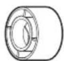
L10mm
Entretoises
F2×4
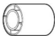
L22mm
Entretoises
F3×4
M4
natural_image
Technical line drawing of a bolt with a flanged head and threaded shaft (no text or symbols)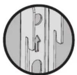
natural_image
Circular diagram showing abstract line patterns with no text or symbolsFlèche vers le haut
natural_image
Pure electrical circuit lines without any symbols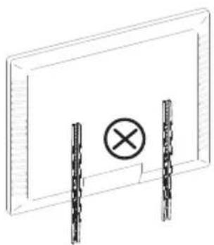
natural_image
Simple line drawing of a rectangular panel with two vertical bars and a central circle containing an 'X' symbol (no text or labels)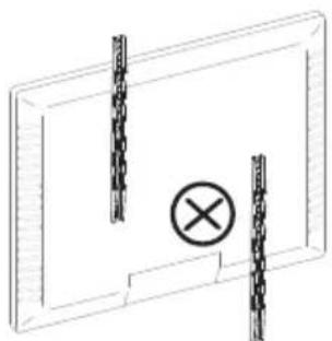
natural_image
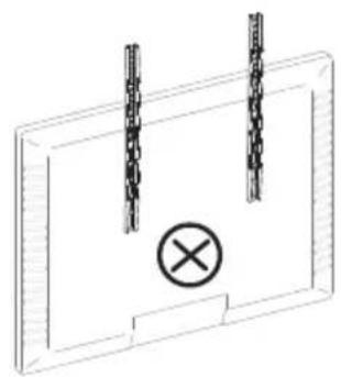
Simple line drawing of a rectangular frame with two vertical chains and a central circle containing an 'X' symbol (no text or labels)natural_image
Pure technical diagram of a mechanical component with no text, numbers, or symbols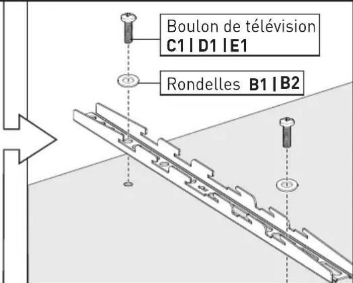
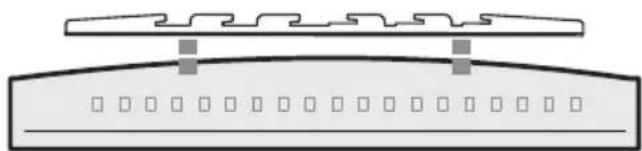
natural_image
Diagram of a device with labeled components and mounting brackets (no text or symbols)Téléviseur incurvé
natural_image
Pure diagram of a mechanical or architectural component with no text, numbers, or symbolsnatural_image
Technical line drawing of a rectangular mechanical part with two oval cutouts (no text or symbols)Plaque TV
05×1

M6 x 10mm
Boulon
K 4
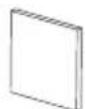
Tampon en EVA
H 4
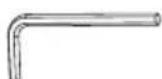
5/32 po (4mm)
Petite clé Allen
P1 x 1

8.5 × 20 × 2mm Rondelle en acier
12
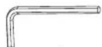
3/16 po (5mm)
Grande clé Allen
P2 x 1
natural_image
Technical line drawing of a T-shaped structural component with internal grid and flange (no text or symbols)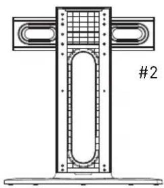
natural_image
Technical line drawing of a T-shaped structural component with internal grid and flanged ends (no text or symbols)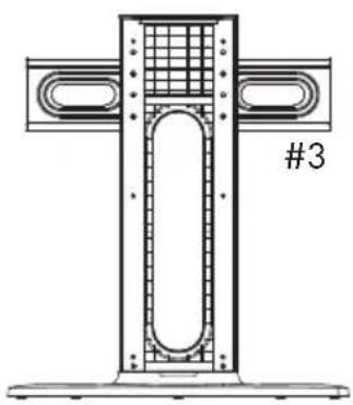
natural_image
Technical line drawing of a structural frame with internal components and a labeled section #3 (no text or symbols beyond the label)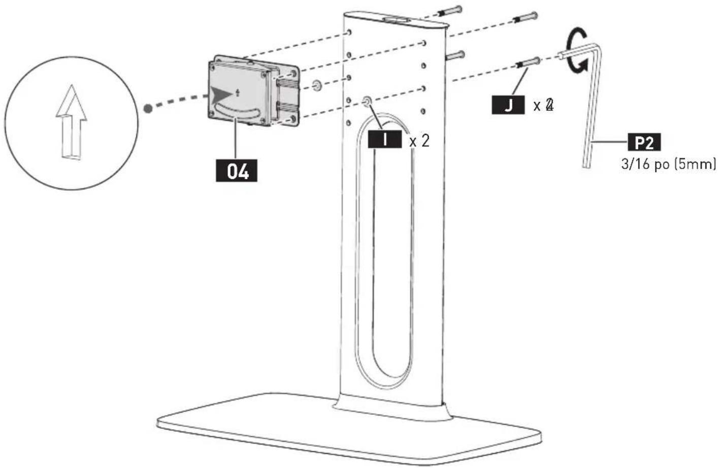
2
natural_image
Simple diagram of a rectangular block with an arrow indicating rotation or force, enclosed in a circle (no text or symbols)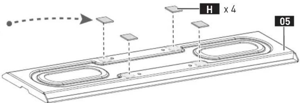
natural_image
Technical line drawing of a mechanical support structure with a circular component on top (no text or symbols)2


natural_image
Line drawing of a computer monitor with a paperclip and scroll holder, showing internal components and directional arrows (no text or symbols)3
natural_image
Technical line drawing of a mechanical assembly mounted on a monitor stand, showing structural components and alignment (no text or symbols)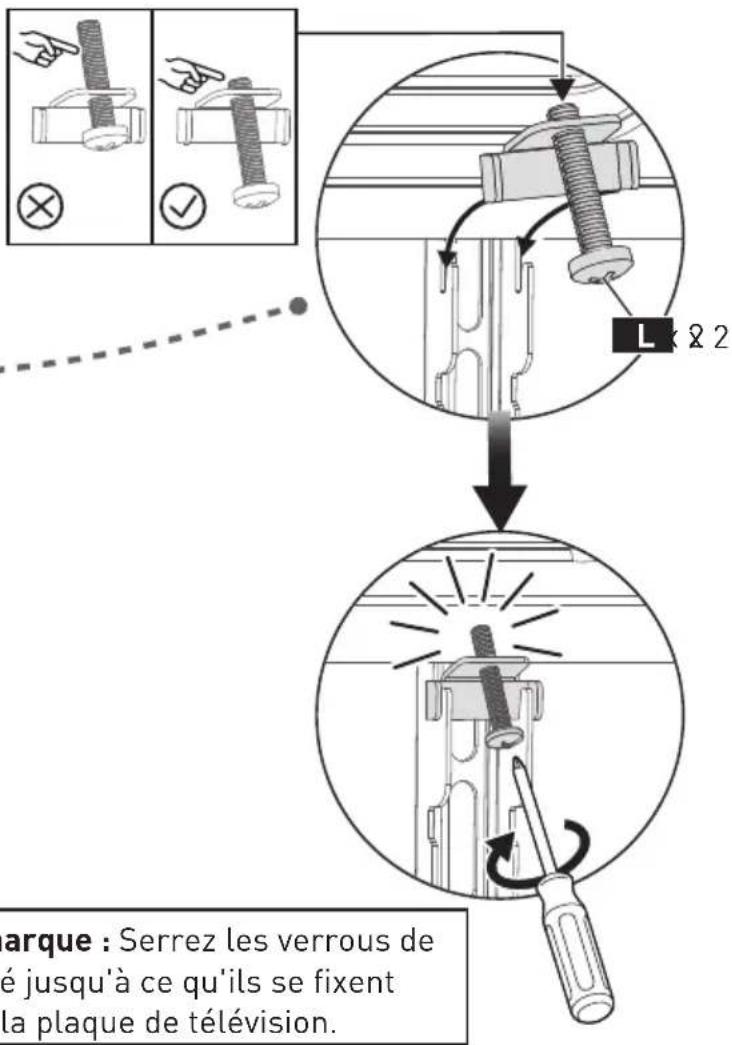
natural_image
Simple diagram with two small circles inside a rectangle (no text or symbols)Gabarit de perçage
07×1
M6 x 50mm Boulon
M×2

6.5×16×2mm
Rondelle en acier
N 2
x 1
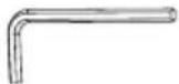
5/32 po (4mm)
Petite clé Allen

natural_image
Diagram showing two mechanical lever mechanisms with alignment guides, no text or symbols present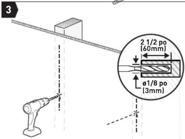
natural_image
Technical line drawing of a structural joint or bracket assembly, labeled 'Rendez-vous' at the bottom (no other text or symbols)natural_image
Diagram of two mechanical lever arms mounted on a beam, with dashed lines indicating motion or alignment (no text or symbols)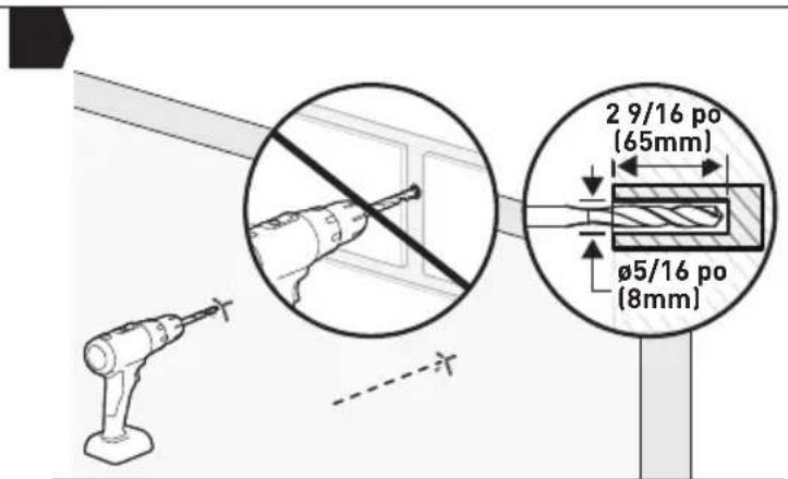
⚠️ Remarque :
natural_image
Technical line drawing of a mechanical assembly with a bracket and mounting base (no text or symbols)natural_image
Diagram of a computer monitor with directional arrows indicating rotation or movement (no text or symbols present)ANTES DE EMPEZAR, ASEGURÉMONOS DE QUE ESTE SOPORTE SEA COMPATIBLE
1
natural_image
Simple line drawing of a slope with two blocks and a checkmark icon (no text or symbols)Perfecto
natural_image
Simple line drawing of a building with a checkmark and a magnified view of its exterior (no text or symbols)Perfecto
natural_image
Technical line drawing of a mechanical component with multiple circular features and dimension lines (no text or symbols)Soporte de TV
01×2
M4/M5
Arandela
B1×4
M6/M8
Arandela
B2×4
D8 Arandela
B3×4
L2.5mm Espaciador
F1 x 8
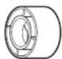
L10mm Espaciador
F2 x 4
natural_image
Technical line drawing of a bolt with a flanged head and threaded shaft (no text or symbols)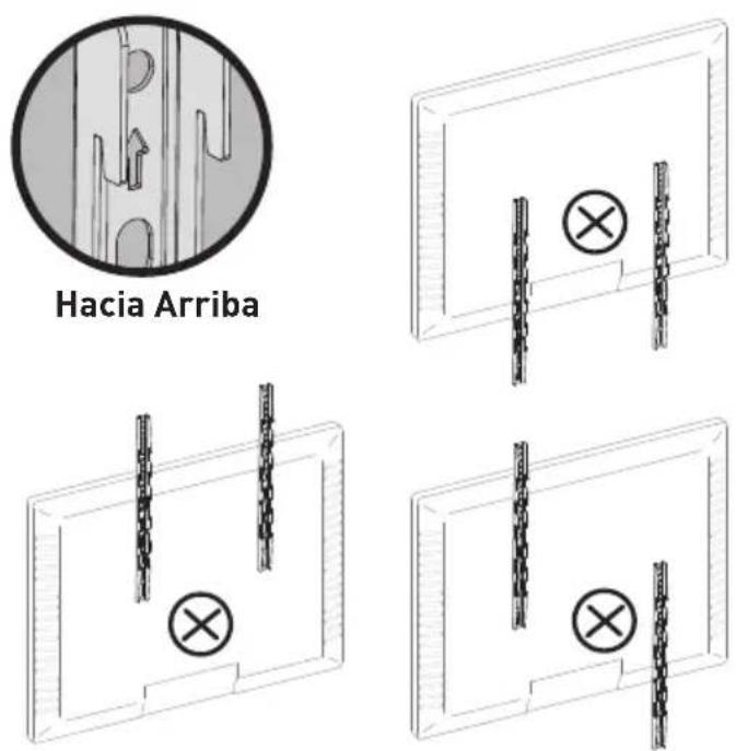
natural_image
Pure technical diagram of a mechanical component with no text, numbers, or symbols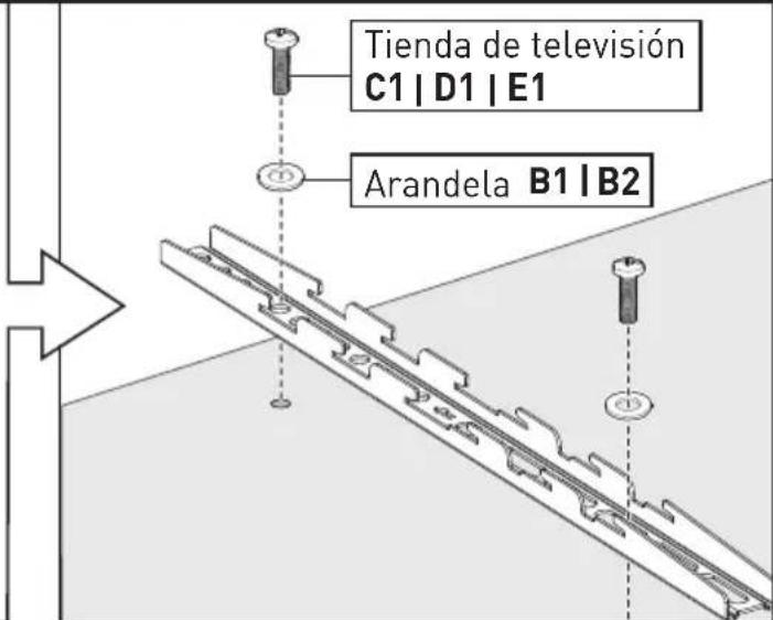
natural_image
Diagram of a device with two top views and a control panel, no text or symbols presentTelevisor curvo
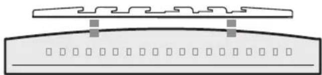
natural_image
Pure diagram of a mechanical or structural component with no text, numbers, or symbolsnatural_image
Technical line drawing of a rectangular mechanical part with two oval cutouts (no text or symbols)Placa de TV
05×1

M6 x 10mm
Perno
K 4
Almohadilla de EVA
H 4
4mm (5/32 pulg)
Llave Allen pequeña
P1 x 1

8.5×20×2mm
Arandela de acero
12

5mm (3/16 pulg)
Llave Allen grande
P2 x 1
natural_image
Technical line drawing of a T-shaped structural component with internal grid and flanged ends (no text or symbols)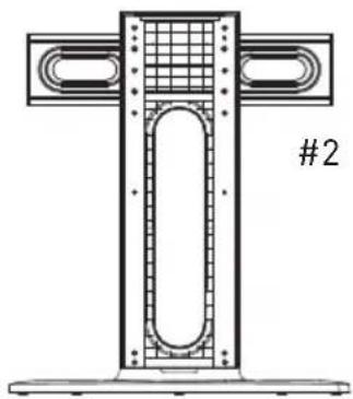
natural_image
Technical line drawing of a T-shaped structural component with internal grid and flanged ends (no text or symbols)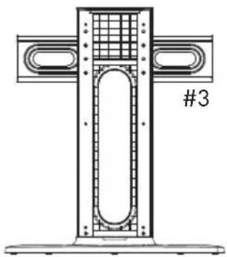
natural_image
Technical line drawing of a structural frame with grid and oval elements, labeled #3 (no text or symbols beyond label)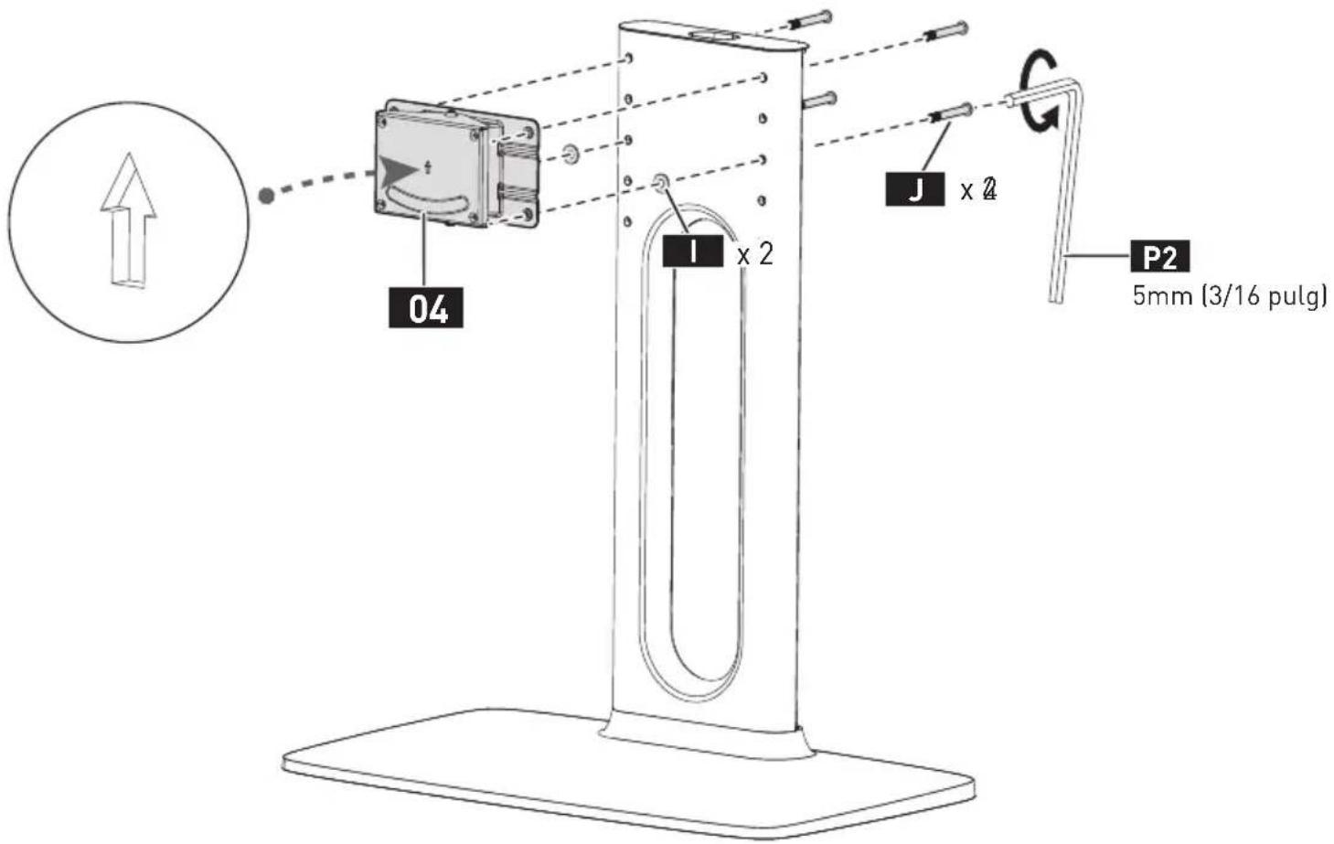
2
natural_image
Simple 3D diagram of a rectangular block with an arrow indicating rotation or compression (no text or symbols)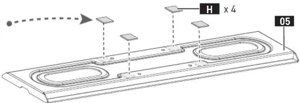
natural_image
Technical line drawing of a mechanical support structure with a circular component inserted (no text or symbols)2


natural_image
Technical line drawing of a computer monitor with a paperclip and scroll holder (no text or symbols)3
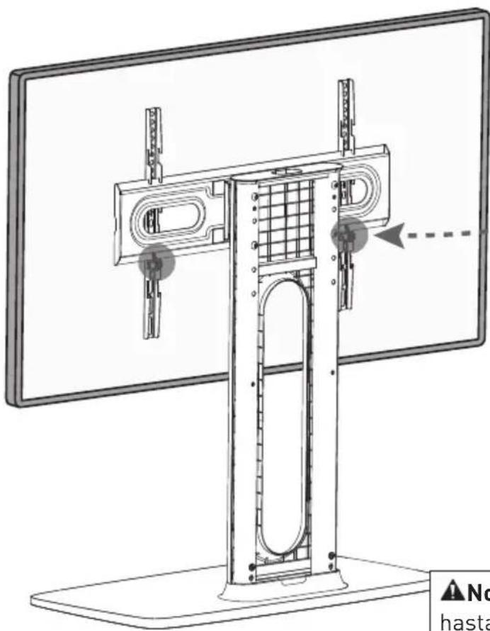
natural_image
Technical line drawing of a monitor stand with internal components and a dashed arrow indicating motion (no text or symbols)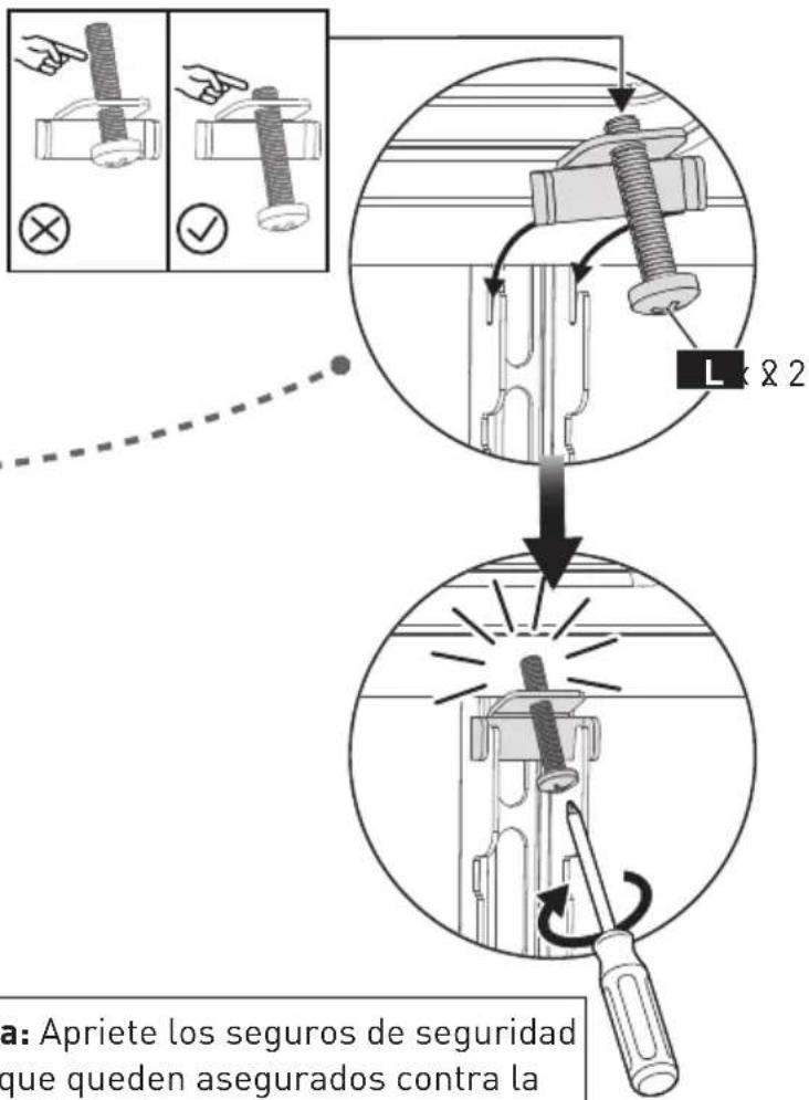
natural_image
Simple diagram with two empty circles inside a rectangle (no text or symbols)The image is too blurry to recognize any text content.
natural_image
Diagram showing two mechanical lever mechanisms with dashed alignment lines, no text or symbols present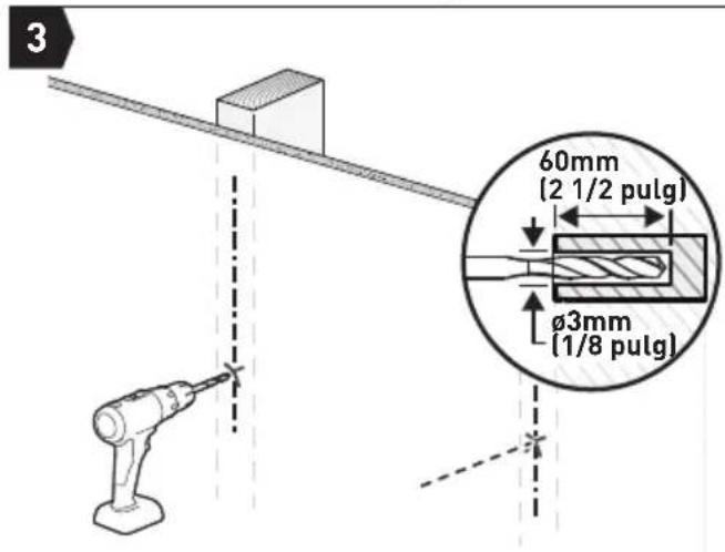
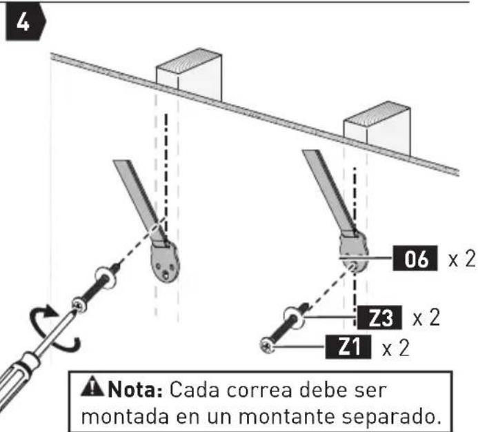
natural_image
Technical line drawing of a mechanical assembly with a vertical component and base (no text or symbols)natural_image
Diagram of two mechanical clamps hanging from a beam, with no text or symbols present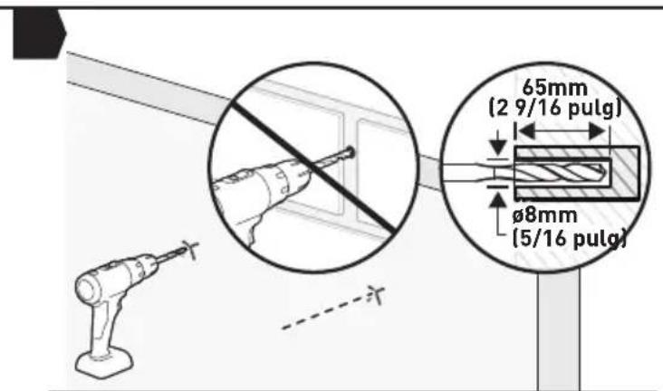
Nota:
natural_image
Technical line drawing of a mechanical assembly with a bracket and mounting base (no text or symbols)PASO 8 Ajuste giratorio
natural_image
Diagram of a computer monitor with directional arrows indicating rotation or movement (no text or symbols present)ERGOAV™
At ErgoAV, our goal is to provide the high-quality audio video solutions and product support that you need. If you have any questions, concerns, or feedback, please let us know!
natural_image
Technical line drawing of a mechanical assembly with no visible text or symbolsTV Mounts
natural_image
Simple line drawing of a vertical cylindrical structure with two legs and a central horizontal bar (no text or symbols)Speaker Stands
natural_image
Technical line drawing of a Y-shaped mechanical assembly with two arms and a central shaft (no text or symbols)Computer Monitor Mounts
(877) 419-7832 Mon-Fri 8am - 8pm (CST)
support@ergoav.com
www.ergoav.com
ErgoAV
9501 Louisiana Ave N, #200, Brooklyn Park, MN 55445

- ERTSX2
- Thank You for Choosing ErgoAV!
- BEFORE GETTING STARTED, LET'S MAKE SURE THIS STAND IS COMPATIBLE
- 1
- Compatible VESA Patterns:
- Maximum/Minimum:
- 2
- WARNING
- 3
- 4
- For safety bolt installation
- For safety strap installation into wood
- 5
- Supplied Parts and Hardware for Step 1
- M4
- M6
- M8
- STEP 1 Attach the TV Brackets to Your TV
- 1-1 Select TV Bolts
- 1-2 Position the TV Brackets
- 1-3 Secure the TV Brackets
- WARNING:
- Option A
- Flat-Back TV
- Option B
- Note:
- Supplied Parts and Hardware for Step 2
- STEP 2 Connect the Support Pillar to the Base
- Supplied Parts and Hardware for Step 3
- STEP 3 Secure the TV Plate to the Support Pillar
- Supplied Parts and Hardware for Step 4
- STEP 4 Hang the TV on the TV Plate
- Supplied Parts and Hardware for Step 5
- STEP 5 Manage the Cables and Attach the Back Cover
- Supplied Parts and Hardware for Step 6
- STEP 6 Secure the Base to the Wooden Table Furniture (Optional)
- Supplied Parts and Hardware for Step 7
- STEP 7 Secure the TV Stand against the Furniture or Wall
- Option A: For Wooden Table Furniture Installation
- Option B: For Wood Stud Installation
- Option C: For Concrete and Concrete Block Wall Installation
- STEP 8 Swivel Adjustment
- AVANT DE COMMENCER, ASSUREZ-VOUS QUE CE SUPPORT EST COMPATIBLE
- ⚠️ Remarque :
- ANTES DE EMPEZAR, ASEGURÉMONOS DE QUE ESTE SOPORTE SEA COMPATIBLE
- Nota:
- PASO 8 Ajuste giratorio
- ERGOAV™
Brand : ErgoAV
Model : ERTSX2-01B
Category : TV Stand