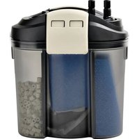
FES 200 - Water filter EDEN - Free user manual and instructions
Find the device manual for free FES 200 EDEN in PDF.


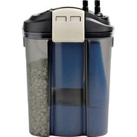
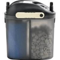
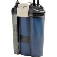
| Product type | External aquarium filter (model EDEN FES 200) |
| Brand | Eden |
| Model | FES 200 |
| Usage | Water filtration for freshwater or saltwater aquariums, indoor, private use |
| Recommended aquarium volume | Up to 200 L |
| Max flow rate | 800 L/h |
| Max delivery head | 1.1 m |
| Max water column | 1.8 m |
| Filter volume | 4.2 L |
| Pre-filter volume | 1.5 L |
| Dimensions (L x W x H) | 290 x 180 x 330 mm |
| Weight | 3.7 kg |
| Power supply | 230 V, 50 Hz |
| Power consumption (filter) | 17 W |
| Power consumption (optional heater) | 200 W (optional, via RCA 200 kit) |
| Protection rating | IPX8 (continuous immersion up to 1 m depth) |
| Protection class | II (reinforced insulation) |
| Supplied filter media | Filter foam 10 ppi (1), foam 20 ppi (1), ceramic substrate (2 bags of 420 g), activated carbon in filter bag (2) |
| Filtration types | Mechanical (foams), biological (ceramic), chemical (activated carbon) |
| Hose connection | Diameter 17 mm, supplied hose length 2.5 m |
| Power cable length | 1.5 m |
| Routine maintenance | Clean foams with hot water, replace carbon and substrate as needed |
| Wear parts | Suction cups, rotor block, filter foams, activated carbon, ceramic substrate |
| Included accessories | Suction tube, return tube, water distributor, suction cups, clips, adapters, intake strainer |
| Heater compatibility | Optional via EDEN RCA 200 conversion kit (ref. 95498) |
Frequently Asked Questions - FES 200 EDEN
User questions about FES 200 EDEN
0 question about this device. Answer the ones you know or ask your own.
Ask a new question about this device
Download the instructions for your Water filter in PDF format for free! Find your manual FES 200 - EDEN and take your electronic device back in hand. On this page are published all the documents necessary for the use of your device. FES 200 by EDEN.
USER MANUAL FES 200 EDEN
EN Operating instructions
FR Notice d'emploi
Original-Anleitung.
Sicherheitshinweise
FST0057
Heizer nachrüsten
FST0064
VORSICHT
FST0063
FST0067
Gerätekopf ausbauen
FST0069
Gerätekopf einbauen
DE
So gehen Sie vor:
FST0068
VORSICHT
FST0060
IN
OUT
FST0062
HINWEIS
FST0014
VORSICHT
EDEN
FES 100
FET 100
EDEN
FES 200
FET 200
EDEN
FES 300
FET 300
FST0070
Electrical connection
- Only connect the unit if the electrical data of the unit and the power supply match.
- Only plug the unit into a correctly installed outlet.
- Protect open plugs and sockets from moisture.
Safe operation
- Disconnect all electrical devices in the water from the power supply before reaching into the water. Otherwise there is a risk of severe injuries or death by electrocution.
- Do not use the unit, if electrical lines or the housing are damaged.
- The supply cord cannot be replaced. If the cord is damaged, the appliance should be scrapped.
- Never pull on electric cables. In particular, never carry units on their cables.
- Route lines in such a way that they are protected from damage and do not present a tripping hazard.
- Do not use the unit together with chemicals, food, flammable, explosive substances or other liquids aside from water.
- This unit can be used by children aged 3 and above and by persons with reduced physical, sensory or mental capabilities or lack of experience and knowledge if they are supervised or have been instructed on how to use the unit in a safe way and they understand the hazards involved. Do not allow children to play with the unit. Only allow children to carry out cleaning and user maintenance under supervision.
- Never carry out technical changes to the unit.
- Only use original spare parts and accessories.
- Should problems occur, please contact the authorised customer service or EDEN.
Intended use
Only use the product described in this manual as follows:
• Water filtering and recirculation
- For operation with freshwater or saltwater.
- Indoors and for private aquarium-keeping purposes.
- While adhering to the technical specifications. (→ Technical data)
Product Description
Overview
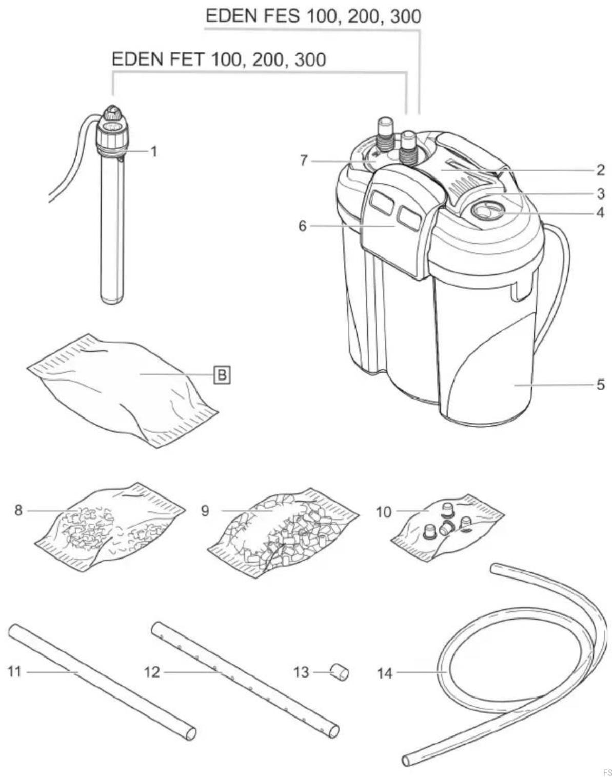
| EDEN FES 100, 200, 300EDEN FET 100, 200, 300 | Quantity | |||
| 100 | 200 | 300 | ||
| 1 | Thermo-control heater with passage ring (EDEN FET 100, 200, 300 only)EDEN FET 100: EDEN RCA 100EDEN FET 200: EDEN RCA 200EDEN FET 300: EDEN RCA 300 | 1 | 1 | 1 |
| 2 | Unit head | 1 | 1 | 1 |
| 3 | Handle, adjustable | - | 1 | 1 |
| 4 | Blind plug | 1 | 1 | 1 |
| 5 | Container, filled with filter media | 1 | 1 | 1 |
| 6 | Locking clip | 2 | 2 | 2 |
| 7 | Connection unit with hose connector, outlet (OUT) and inlet (IN) | 1 | 1 | 1 |
| 8 | Filter bag with activated carbon | - | 2 | 2 |
| 9 | Ceramic substrate | 1 | 2 | 3 |
| 10 | Bag with 4 feet | 1 | 1 | 1 |
| 11 | Suction pipe | 1 | 1 | 1 |
| 12 | Flow-out pipe | 1 | 1 | 2 |
| 13 | Hose section as connecting piece for flow-out pipe (12) | - | - | 1 |
| 14 | Hose | 1 | 1 | 1 |
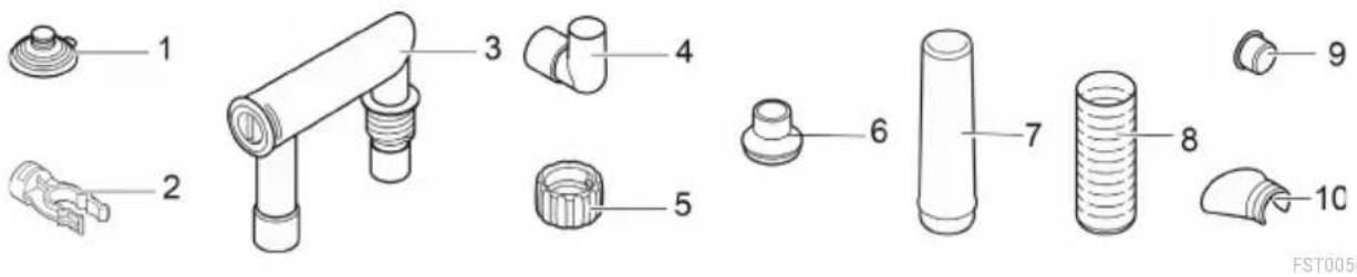
| EDEN FES 100, 200, 300EDEN FET 100, 200, 300 | Quantity | |||
| 100 | 200 | 300 | ||
| 1 | Suction cup | 5 | 5 | 5 |
| 2 | Terminal | 5 | 5 | 5 |
| 3 | Hose adapter, adjustable | 2 | 2 | 2 |
| 4 | Angle piece | 1 | 1 | 1 |
| 5 | Union nut | 4 | 4 | 4 |
| 6 | Adapter, suction pipeEDEN FES 100 | EDEN FET 100 | 1 | - | - |
| 7 | Adapter, suction pipeEDEN FES 200, 300 | EDEN FET 200, 300 | - | 1 | 1 |
| 8 | Suction basket | 1 | 1 | 1 |
| 9 | Cover cap | 1 | 1 | 1 |
| 10 | Water distributor | 1 | 1 | 1 |
Function description
Drawn in by a pump in the unit head, the water flows through two filter chambers arranged next to each other. Then the water flows back into the aquarium via the flow-out pipe or water distributor.
Foam filters with different pore densities, and activated carbon/ceramic substrate serve as filter media.
In units with heater, the water is heated during its passage through the filter system.
FST0057
Retrofitting the heater
EDEN FES 100, 200, 300 can be equipped with the heater EDEN RCA.
EDEN RCA
Assembly requires the heater retrofitting set:
• EDEN FES 100: EDEN conversion set 95497
• EDEN FES 200: EDEN conversion set 95498
• EDEN FES 300: EDEN conversion set 95499
Symbols on the unit
| IPX8 1.0 m | The unit is protected against the results of permanent immersion in water to a depth of 1 m. | |
 | Protection class II, reliable electrical isolation from the mains by reinforced or double insulation. | |
 | Only use the unit in indoor spaces. | |
 | Do not dispose of the unit with normal household waste. | |
 | Read the operating instructions. | |
Accessing the unit Removing the heater
CAUTION
The glass tube of the heater can break and cause cuts.
▶ Take care when handling the heater.
▶ Turn the heater off and let it cool down before removing it from the water.
▶ Do not immerse the hot heater in cold water or pour cold water over it.
CAUTION
Risk of burns from hot surface.
▶ Only switch on the heater when the bulb is submerged in water.
▶ Turn the heater off and let it cool down before removing it from the water.
The heater has to be removed for cleaning and maintenance, and for removing the unit head. How to proceed:
- Unscrew the holding ring together with the heater counter-clockwise.
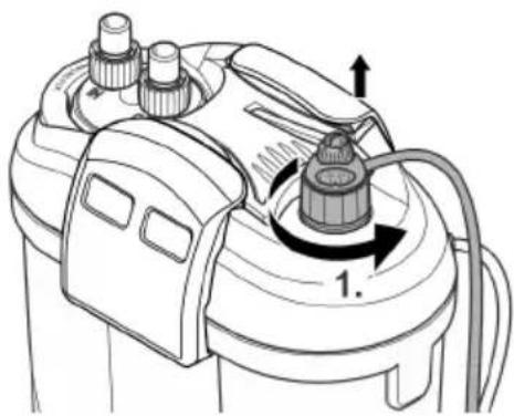
FST0064
Fitting the heater
CAUTION
The glass tube of the heater can break and cause cuts.
▶ Take care when handling the heater.
▶ Turn the heater off and let it cool down before removing it from the water.
▶ Do not immerse the hot heater in cold water or pour cold water over it.
How to proceed:
- Screw the holding ring with heater clockwise into the threaded hole.
- To exchange the heater: Moisten the glass bulb with water and push the heater into the holding ring as far as it goes.
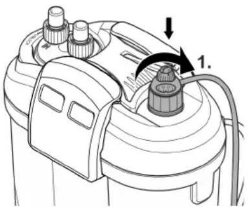
FST0063
Removing the connection unit
The heater has to be removed for cleaning and maintenance, and for removing the unit head when hoses are connected.
How to proceed:
- Turn the bayonet closure in the direction "UNLOCK".
- Remove the connection unit.
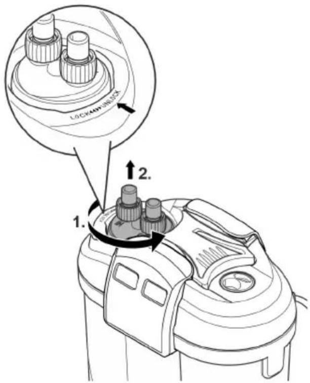
FST0065
Fitting the connection unit
How to proceed:
- Fit the connection unit.
- Ensure that the ridges on the connection unit are correctly aligned to the recesses on the unit head.
- Turn the bayonet closure in the direction "LOCK".
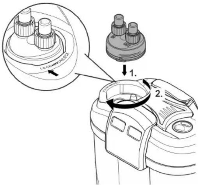
FST0067
Dismantling the unit head
It has to be removed for cleaning and maintenance and for changing the filter media.
Prerequisite:
- The heater has been removed. (→Removing the heater)
- The connection unit has been removed. (→Removing the connection unit)
How to proceed:
- Undo the fasteners.
- Remove the unit head.
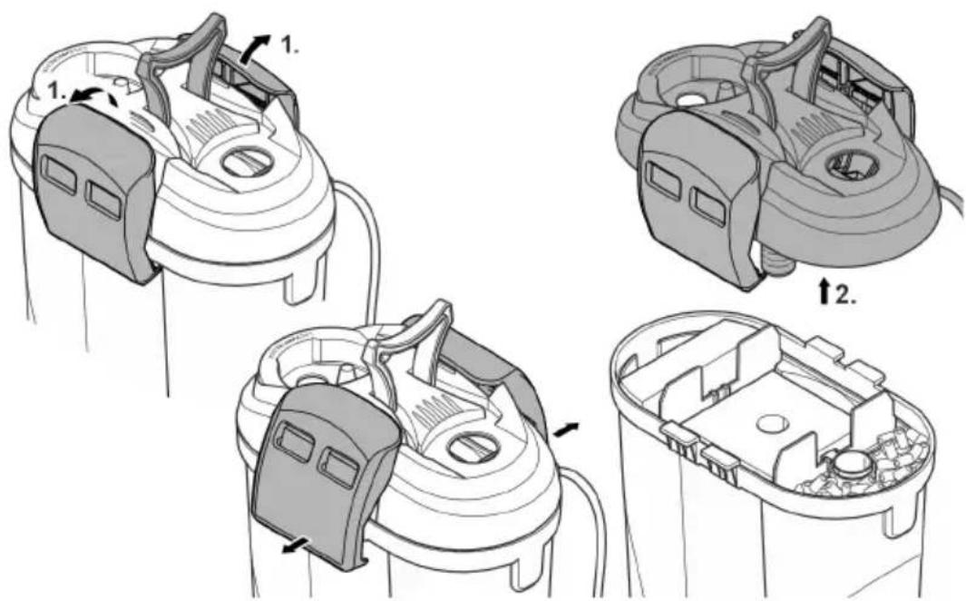
FST0069
Fitting the unit head
How to proceed:
- Check that the seal on the unit head is correctly positioned.
– Clean the seal, replace it if damaged. - Ensure that the vent hose is in place and is pointing upwards.
- Fit the unit head onto the container.
- Hinge all fasteners up and lock them in place.
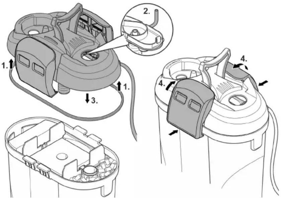
FST0068
CAUTION
The glass tube of the heater can break and cause cuts.
▶ Take care when handling the heater.
▶ Turn the heater off and let it cool down before removing it from the water.
▶ Do not immerse the hot heater in cold water or pour cold water over it.
EN
Prerequisite:
- The unit head is removed. (→ Dismantling the unit head)
How to proceed:
• Steps 1 and 2 do not apply to EDEN FES 100.
- Take out a separating plate.
- Remove any residue from the removal of the separating plate.
- Push the stand into the heater tube.
- Fit the heater tube with tube holder into the recess in the bottom of the container.
- Insert the separating plate again.
- Position the holder and fasten it to the separating plate (EDEN FES 200, 300) or to the container wall (EDEN FES 100).
-
Push the heater into the holding ring as far as it goes.
-
To facilitate installation, moisten the glass bulb of the heater with water.
- Do not fit the heater until all work has been completed. (→ Fitting the unit head)
- Ensure that the O ring is correctly positioned.
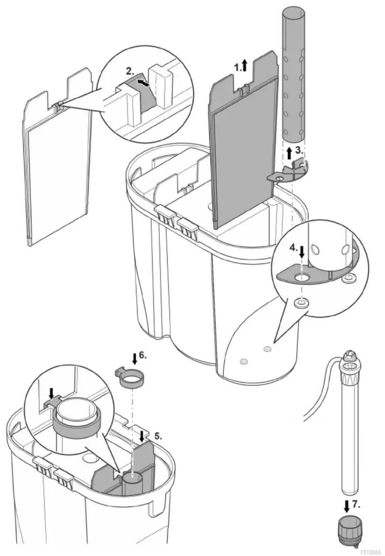
Installation and connection
Order of tasks to be carried out:
- If the unit is to be installed in a standing position: Fit the enclosed rubber feet onto the base of the container.
- Retrofit the heater unit if necessary ( → Fitting the retrofit set)
- Position the filter media (→ Cleaning/replacing the filter media)
- Install the unit.
— Install the unit next to or under the aquarium. Note the maximum head height.
(→ Technical data)
- Establish the connections (→ Establishing the connections)
Establishing the connections
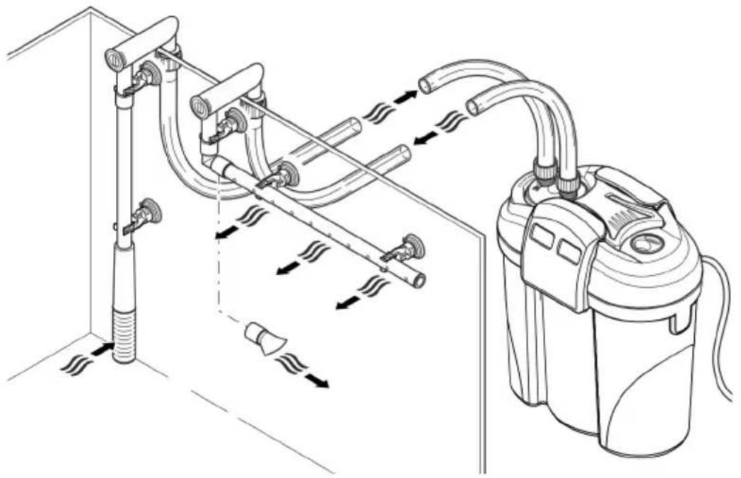
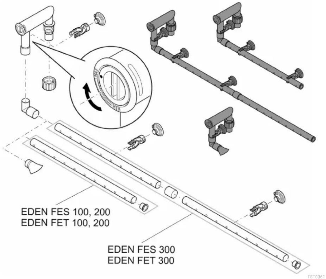
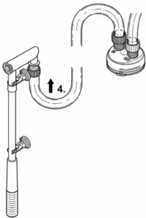
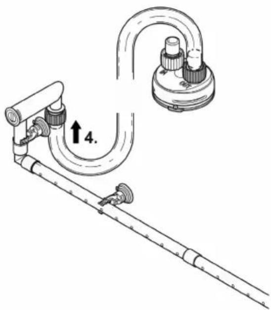
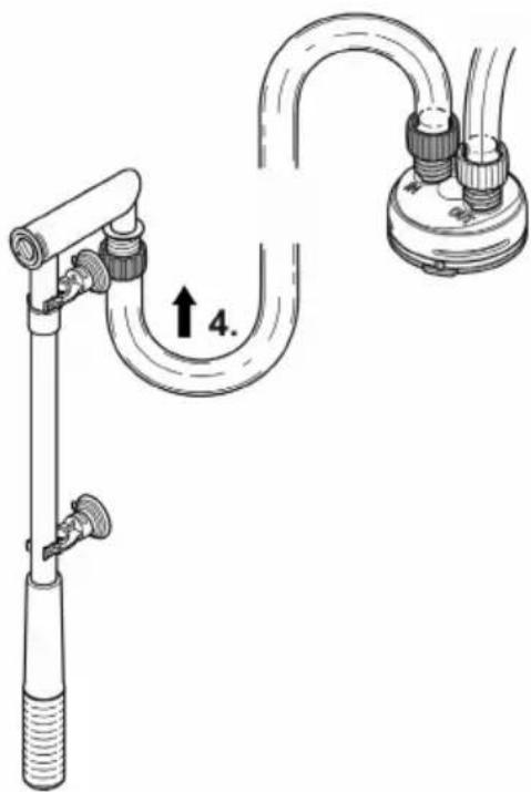
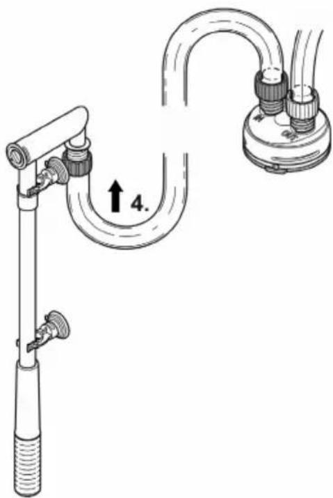
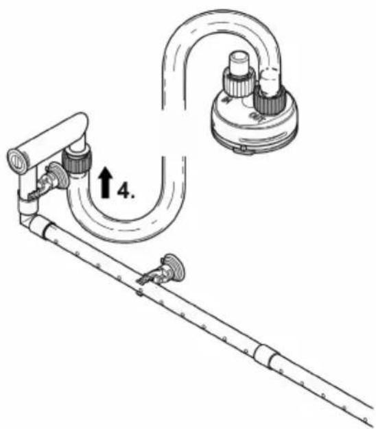
Assembling the suction unit
How to proceed:
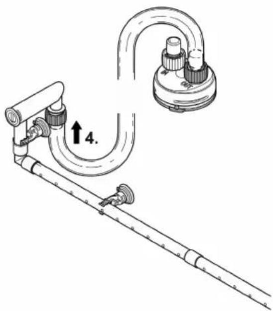
- Assemble the suction unit.
- Set the flow rate.
- Use a coin to turn the flow regulator in the hose adapter in the direction of MIN or MAX.
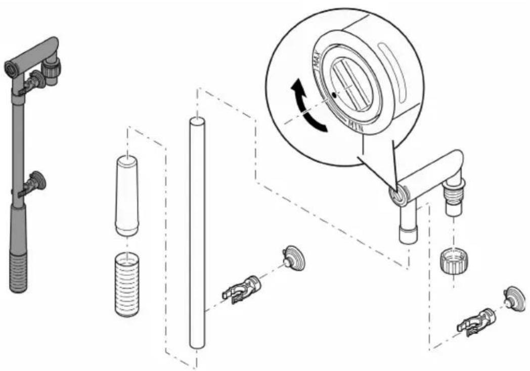
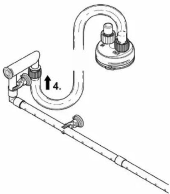
FST0060
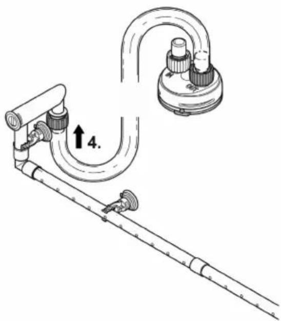
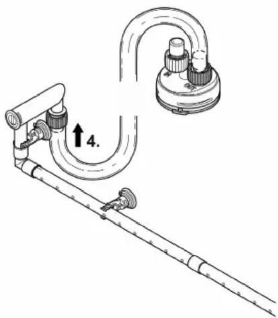
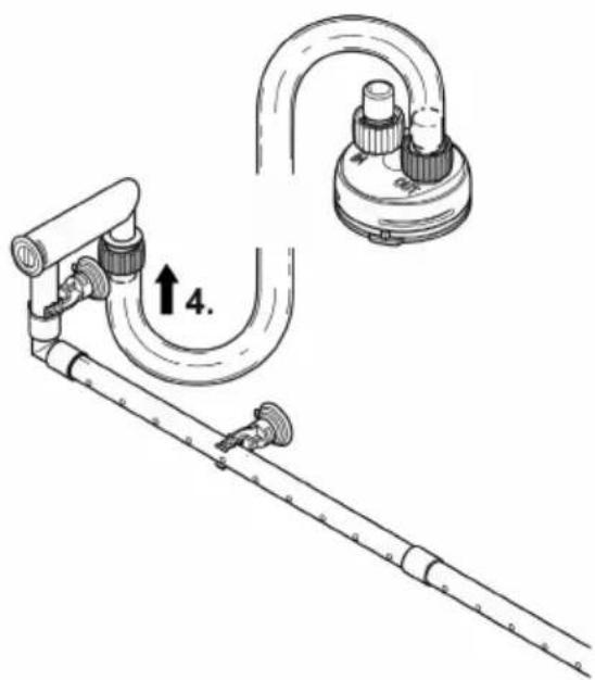
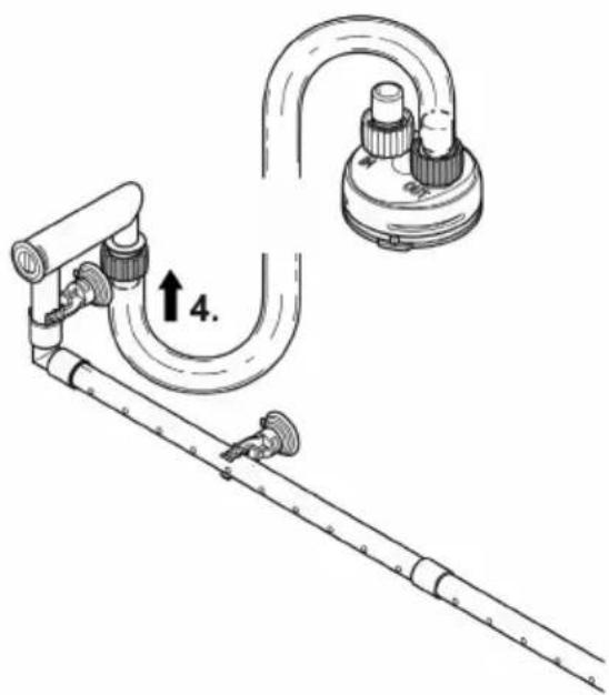
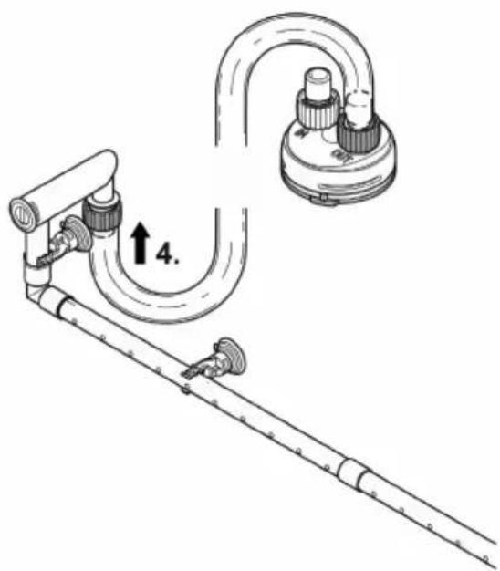
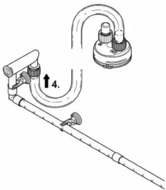
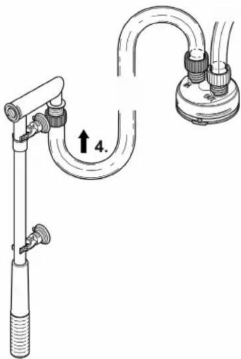
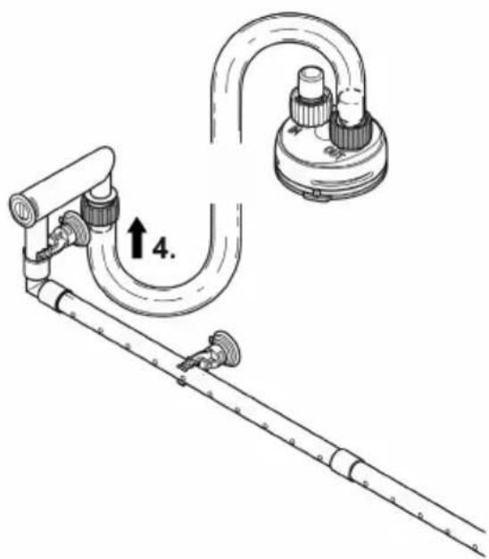
Assembling the flow-out unit
How to proceed:
The water distributor can be used in place of the flow-out pipe.
- Use a coin to turn the flow regulator in the hose adapter to MAX.
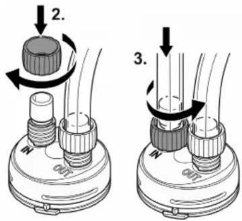
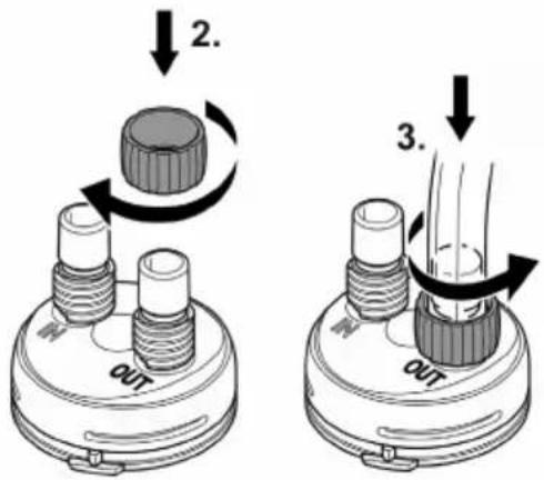
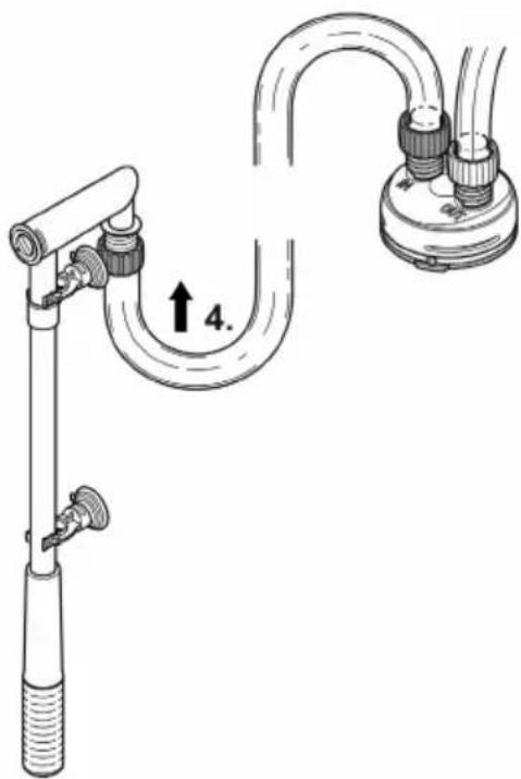
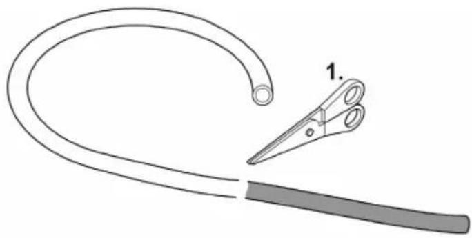
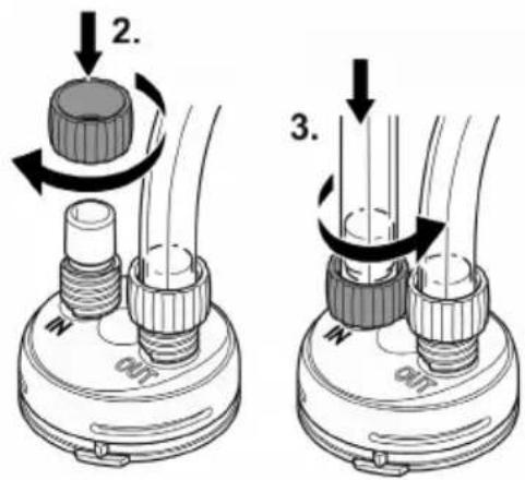
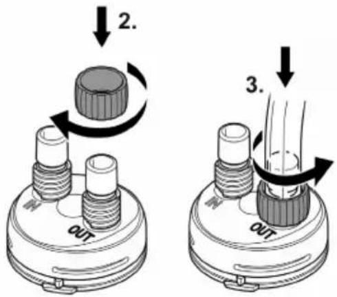
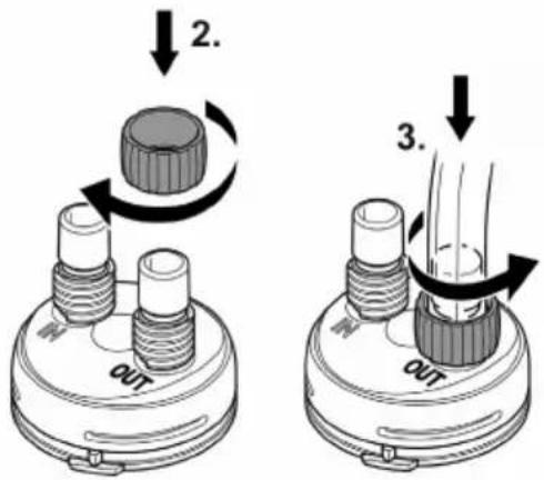
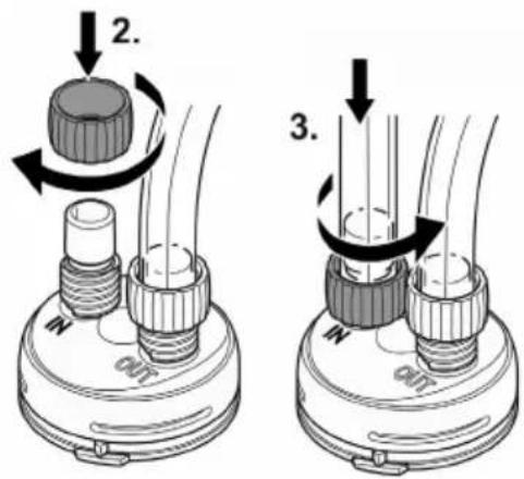
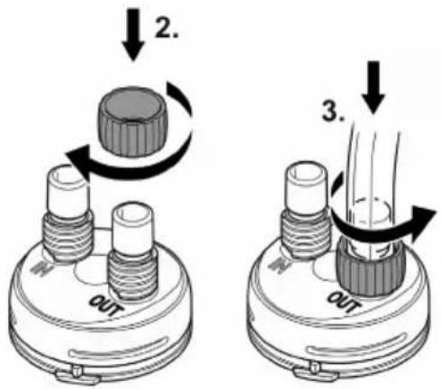
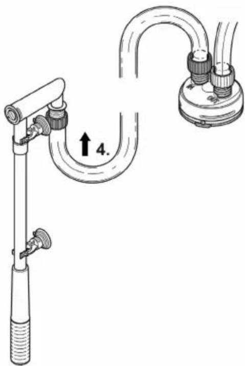
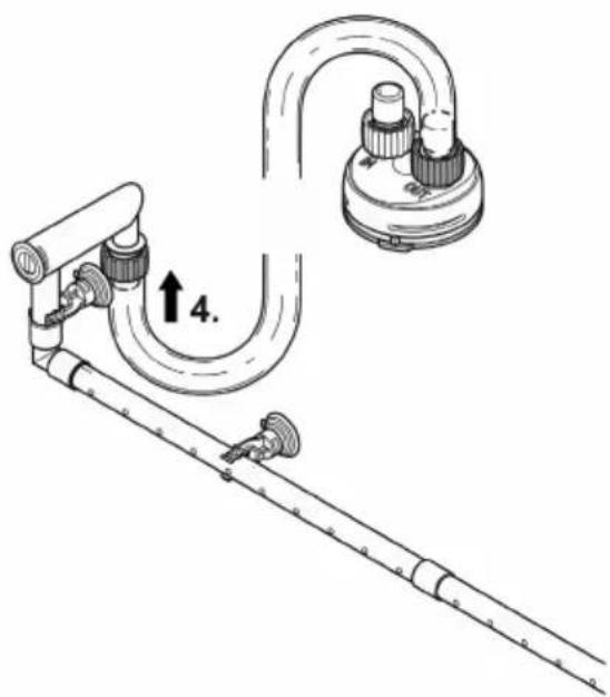
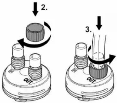
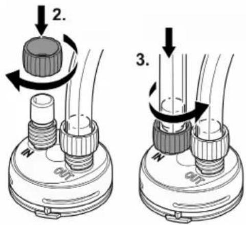
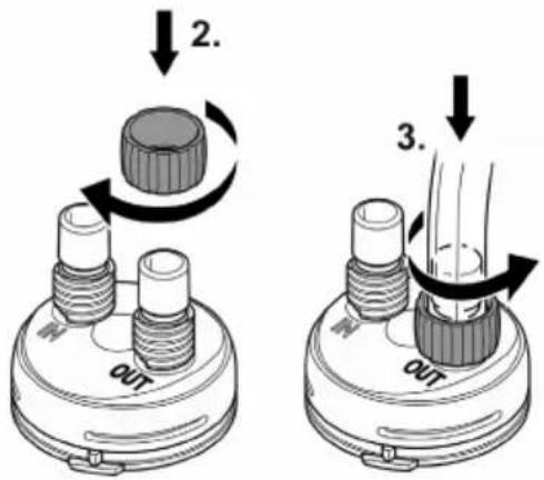
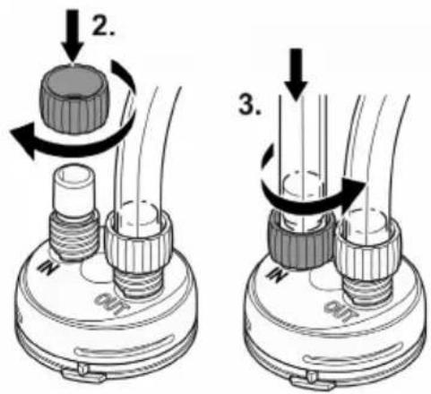
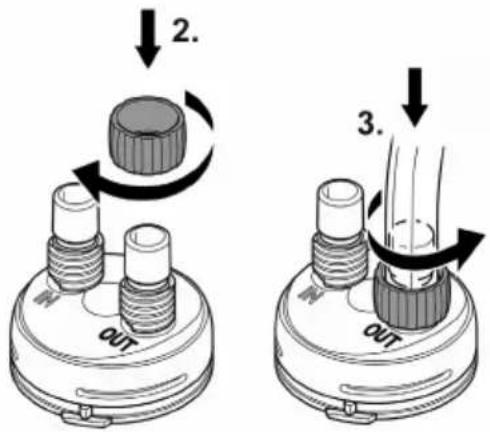
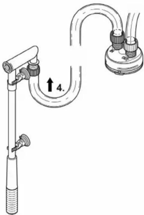
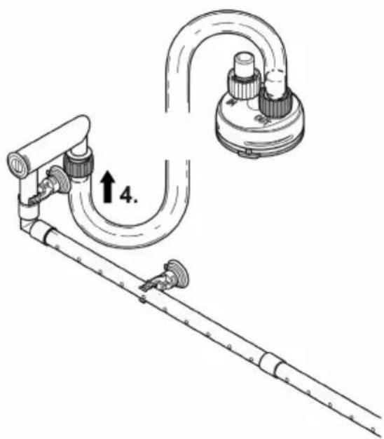
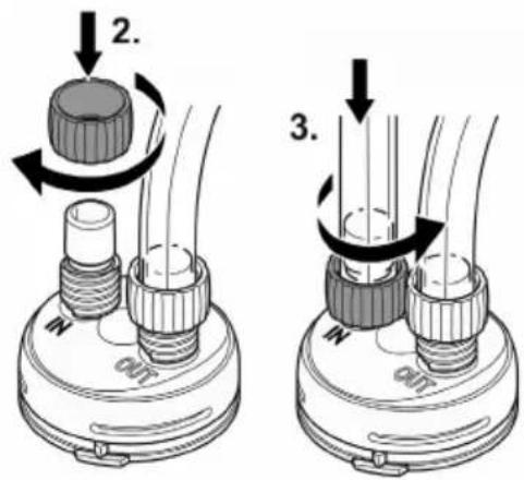
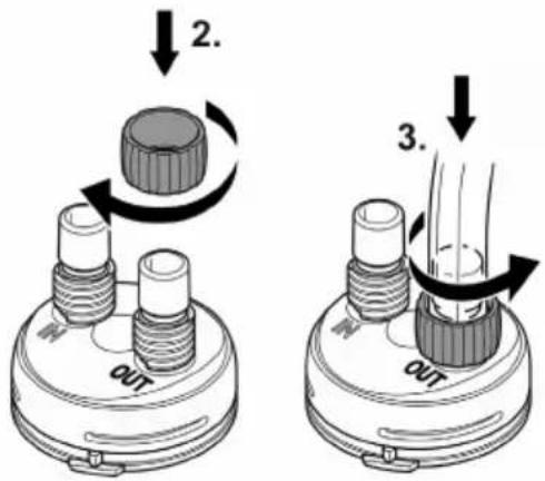
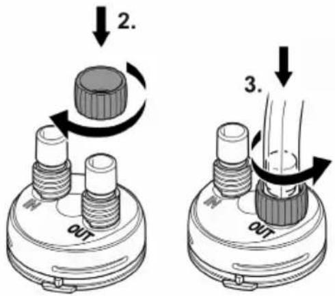
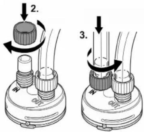
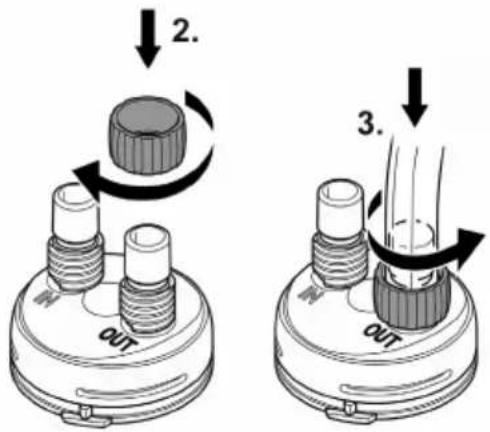
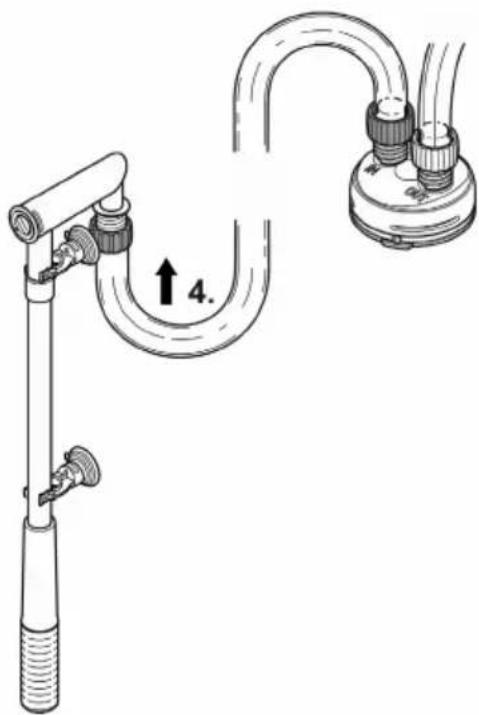
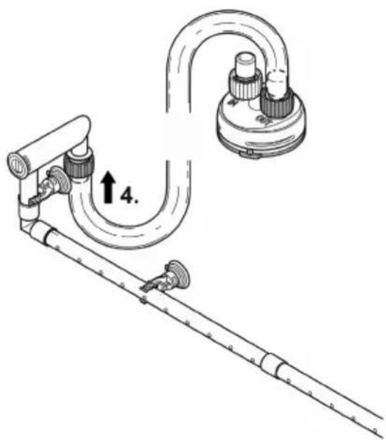
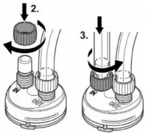
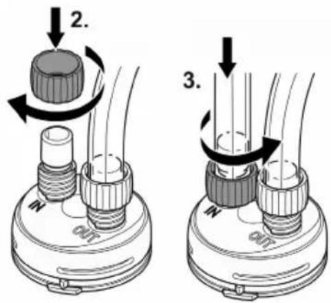
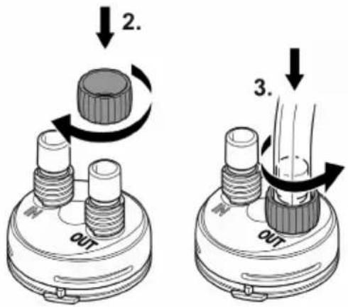
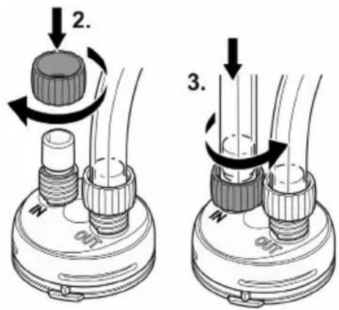
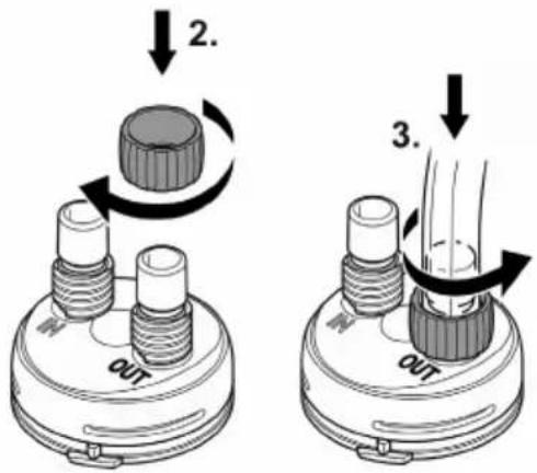
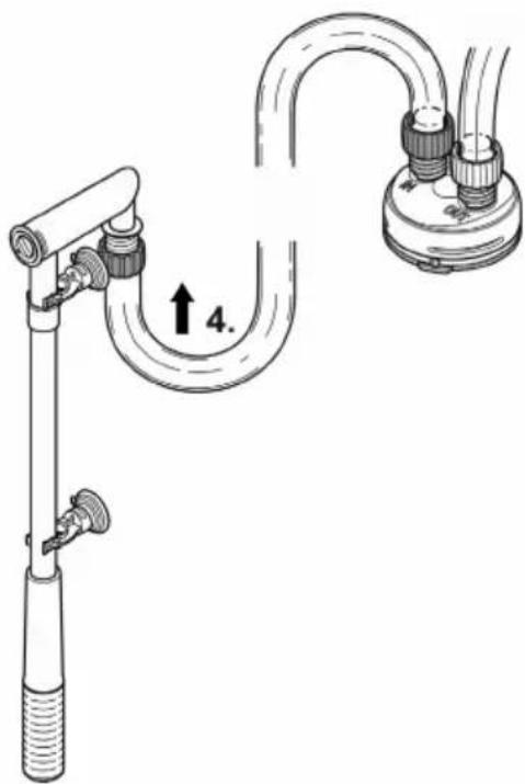
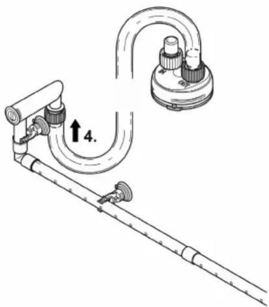
Connecting the hose
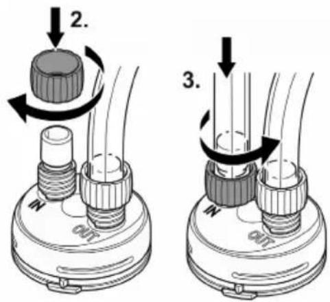
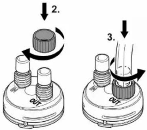
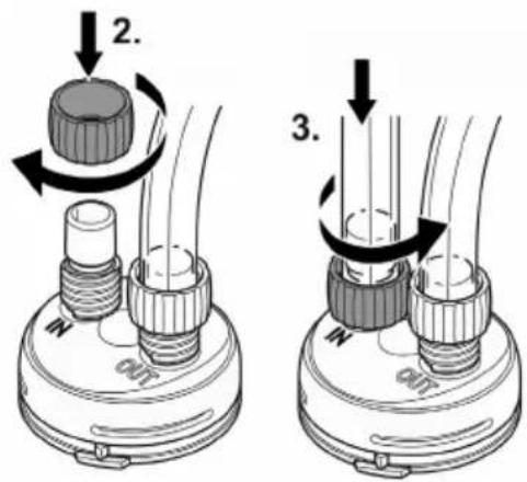
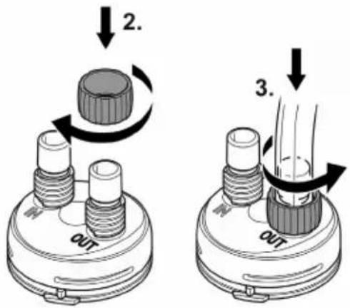
The procedure is identical for the inlet (IN) and outlet (OUT).
How to proceed:
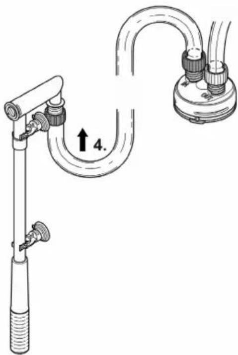
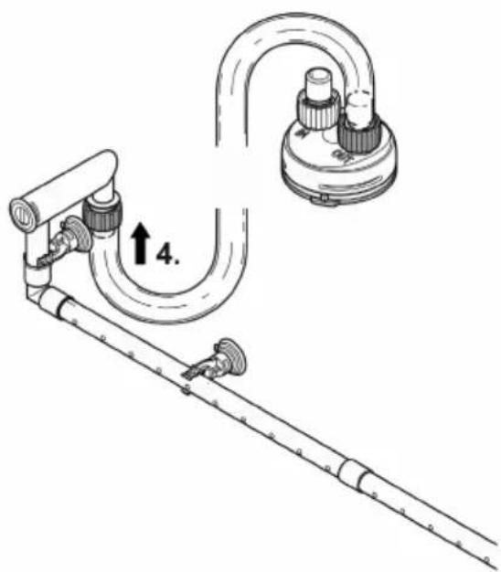
- Shorten the hose to the required length.
- Chose the length so that the hose cannot kink in the intended installation position.
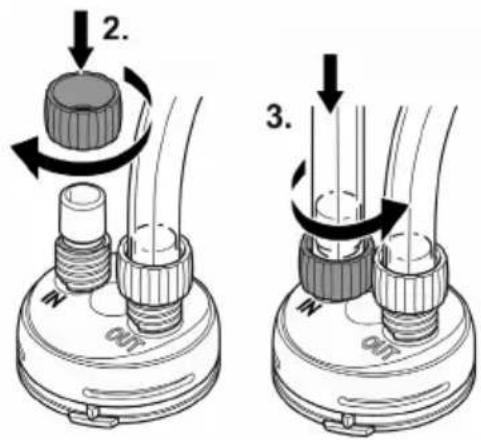
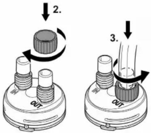
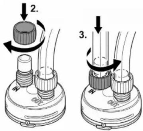
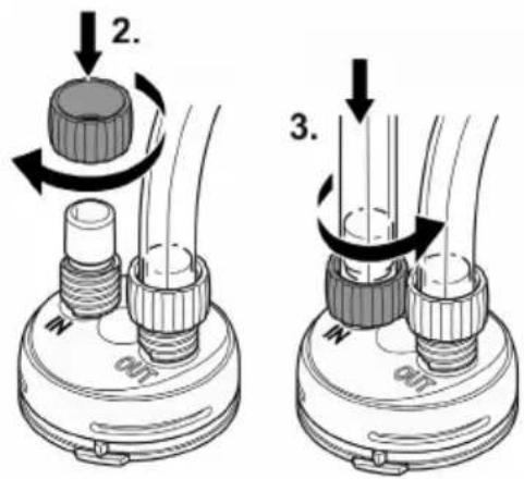
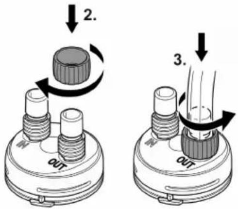
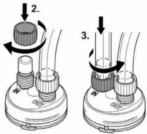
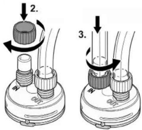
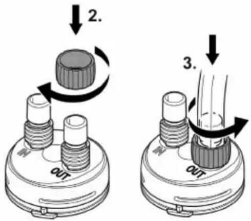
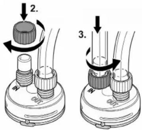
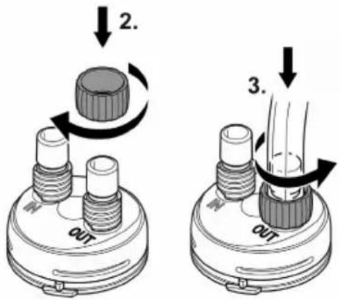
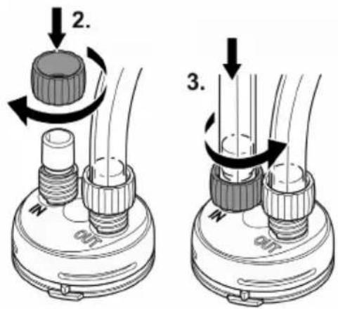
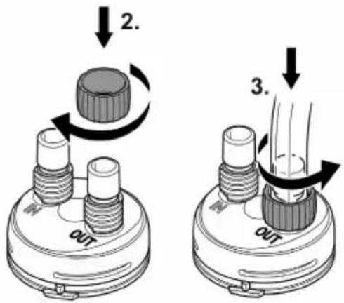
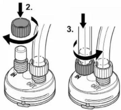
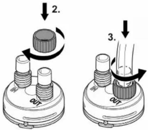
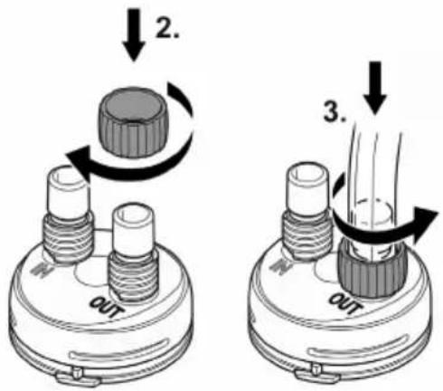
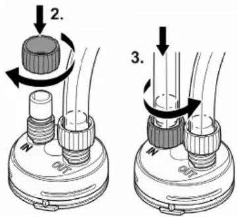
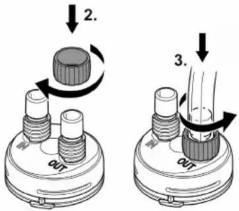
- Screw the union nut onto the hose connector of the connection unit.
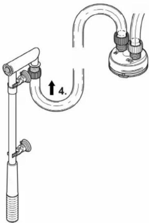
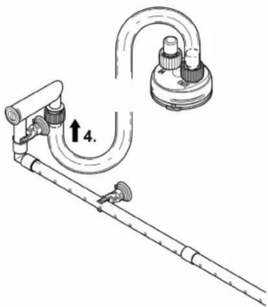
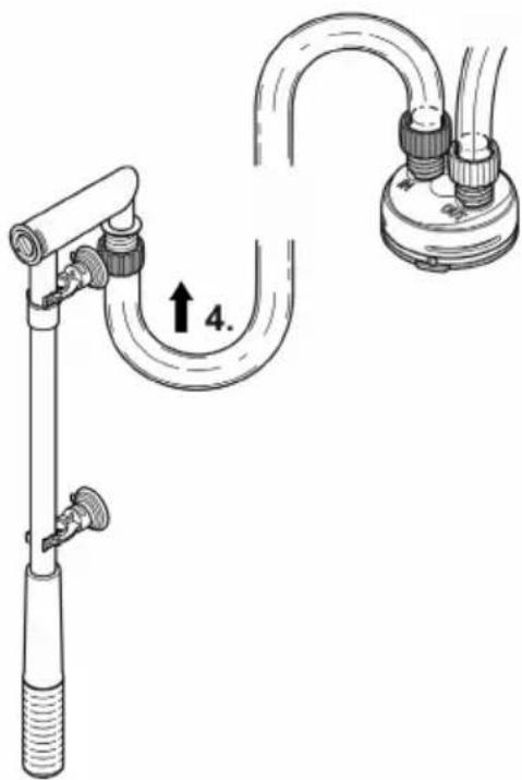
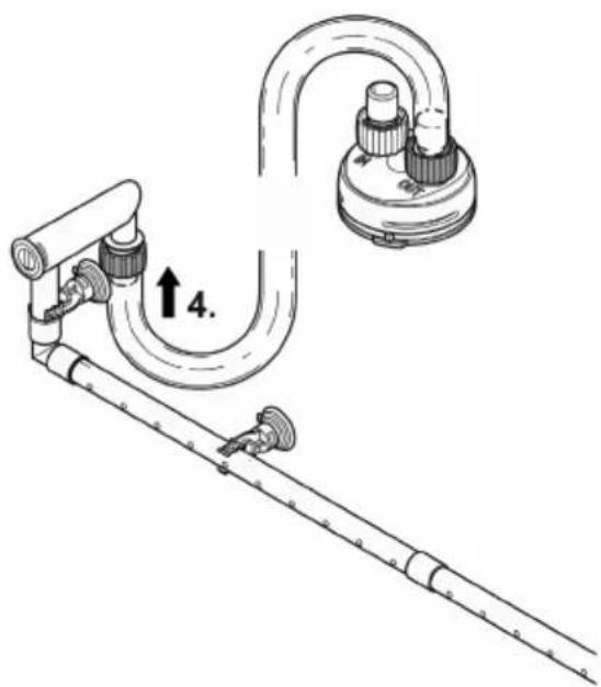
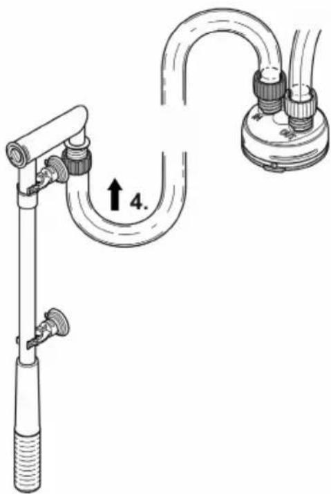
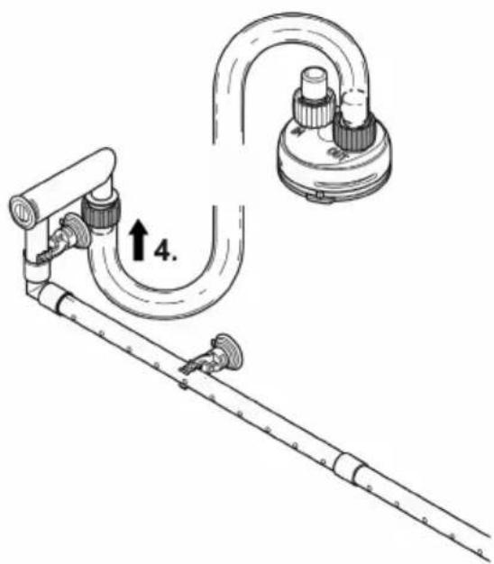
- Push the hose onto the hose connector and turn the union nut counter-clockwise to fix the hose in place.
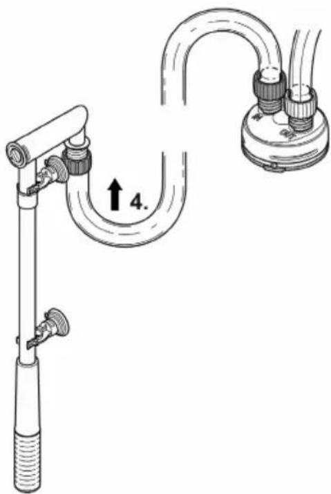
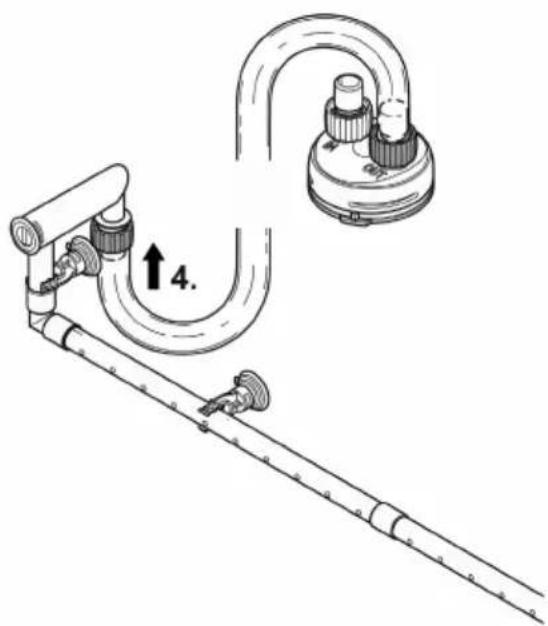
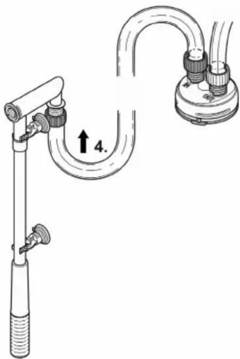
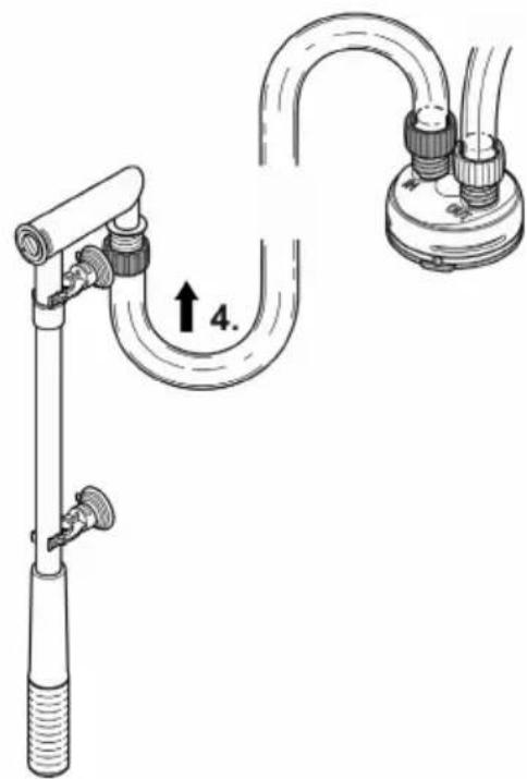
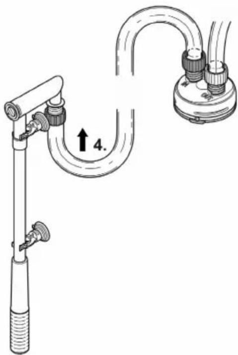
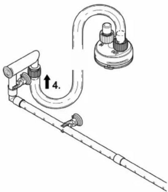
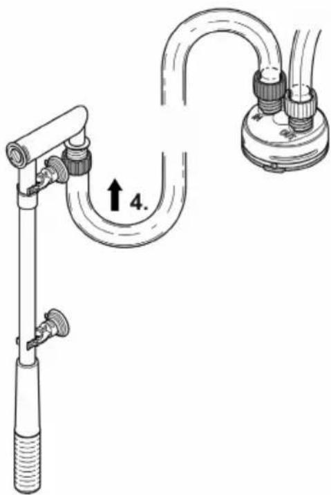
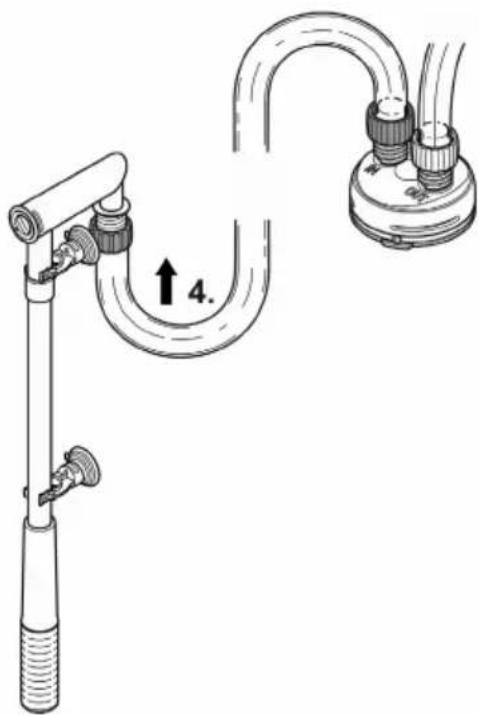
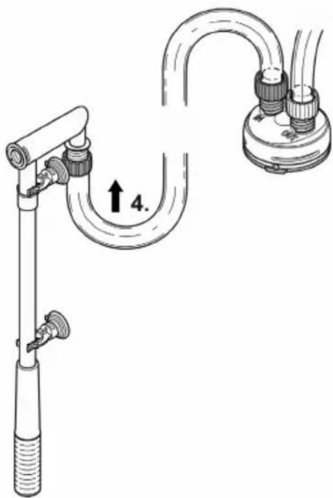
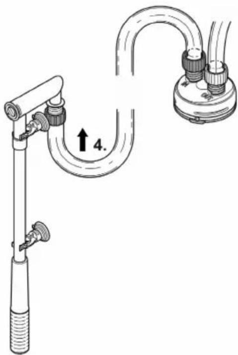
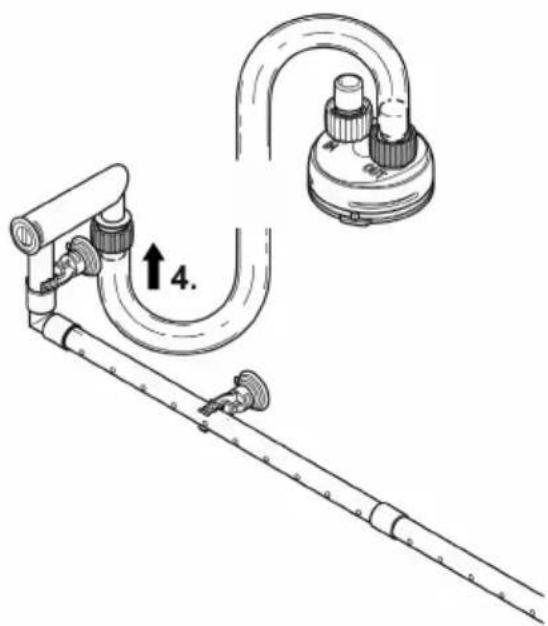
- Push the other end of the hose onto the hose connector at the suction unit/flow-out unit and turn the union nut counter-clockwise to fix the hose in place.
- Fasten the suction unit and flow-out unit in the aquarium using suction cups. (→ Function description)
EN
IN
OUT
FST0062
Commissioning/start-up
NOTE
Never allow the pump to run dry. Otherwise the pump may be destroyed.
▶ Regularly check the water level and circulation in the filter and in the aquarium.
NOTE
Fire hazard due to highly flammable material on hot surface.
▶ Only switch on the heater when it is completely submerged in water.
Remove the packaging from the filter medium. Thoroughly rinse out all filter material with warm tap water before using for the first time in order to remove any soil-ing.(→ Cleaning/replacing the filter media)
How to proceed:
- Completely fill the container with water and place it next to the aquarium.
- Fill the container via the opening for the heater. For this, remove the heater or blind plug. (→Removing the heater)
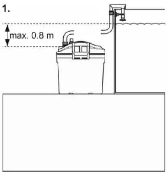
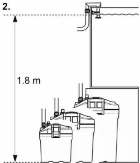
- When starting it up for the first time, ensure that the connection unit is max. 80 cm below the surface of the water. Ensure that the water outlet (flow-out pipe or water distributor) is not submerged.
- A completely filled filter may be more than 80 cm below the surface of the water. Note the maximum head height. (→ Technical data)
- Route each power connection cable such that it forms a drip loop.
- Unit with heater: Set the water temperature on the heater. (→ Heater operating manual).
FST0023
Switching ON/switching OFF
Switching on: Connect the unit to the mains. The unit switches on immediately. When the unit is switched on, it takes several minutes for the air to escape from the unit (this makes a noise).
- Adjust the flow at the flow regulator if necessary. (→ Assembling the suction unit)
Switching off: Disconnect the unit from the mains.
- Unit with heater: Disconnect the unit and heater from the power supply
Maintenance and cleaning
- If necessary, clean with clear water using a soft brush.
- Do not use aggressive cleaning agents or chemical solutions as they could attack the housing or impair the function of the unit.
- Cleaning and replacement cycles for filter media are dependent on the size of the aquarium and the number of fish. Therefore, it is necessary to clean and replace the filter media as required to ensure optimum filter performance.
- If there are several foam filters: Clean or replace the foam filters at different times. This saves enough useful bacteria to ensure good biological filtration of the water.
Cleaning/replacing the filter media
Remove the packaging from the filter medium. Thoroughly rinse out all filter material with warm tap water before using for the first time in order to remove any soil-ing.(→ Cleaning/replacing the filter media)
| Filter media quantity | EDEN FES, EDEN FET | |||
| 100 | 200 | 300 | ||
| a | Foam filter 10 ppi | 1 | 1 | 1 |
| b | Foam filter 20 ppi | 1 | 1 | 1 |
| c | Ceramic substrate (420 g bag) | 1 | 2 | 3 |
| d | Activated carbon | - | 2 | 2 |
| e | Foam filter 10 ppi | - | - | 1 |
EDEN FES 100
EDEN FET 100
EDEN FES 200
EDEN FET 200
EDEN FES 300
EDEN FES 300
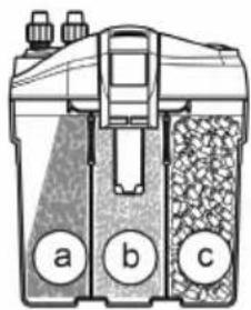
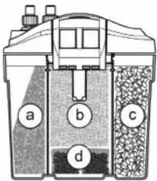
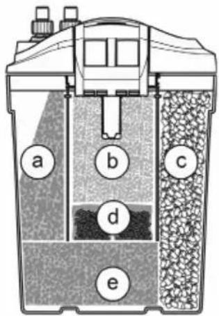
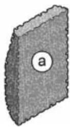
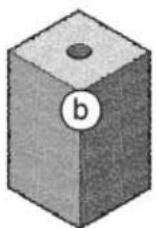
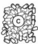

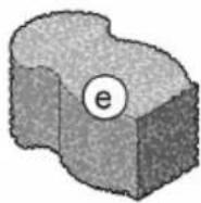
FST0059
Prerequisite:
- The unit head is removed. (→ Dismantling the unit head)
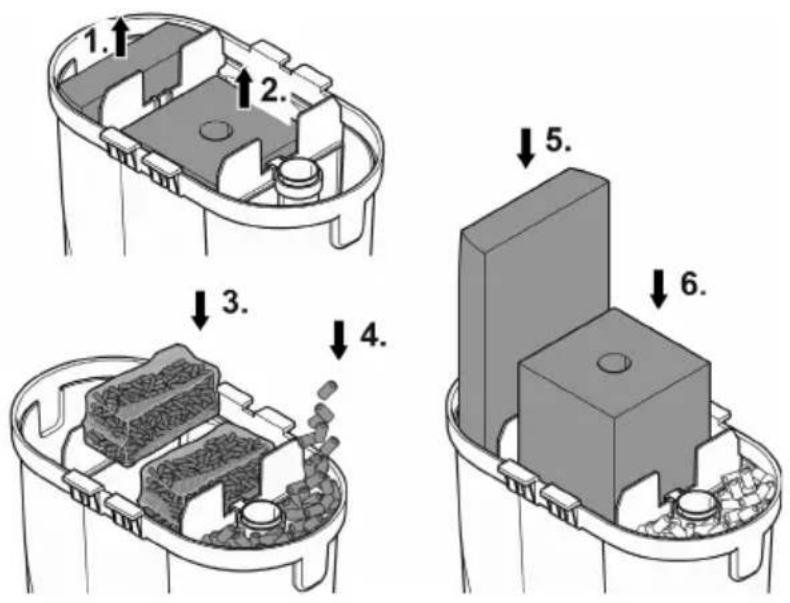
How to proceed:
- Remove the foam filters and rinse in warm water or replace.
- Position the foam filters and activated carbon. The activated carbon has to be taken out of the plastic packaging but remains in its filter bag.
- Rinse the ceramic substrate in warm water or replace.
— Required number of bags (420 g) of ceramic substrate:
- Before using for the first time, remove the ceramic substrate from the plastic bag, rinse it in warm water and put it loosely into the filter container.
- Cover the heater tube, if applicable, when adding the ceramic substrate to ensure that no substrate can enter the heater tube.
FST0014
Cleaning the heater unit
CAUTION
The glass tube of the heater can break and cause cuts.
▶ Take care when handling the heater.
▶ Turn the heater off and let it cool down before removing it from the water.
▶ Do not immerse the hot heater in cold water or pour cold water over it.
CAUTION
Risk of burns from hot surface.
▶ Only switch on the heater when the bulb is submerged in water.
▶ Turn the heater off and let it cool down before removing it from the water.
- Unscrew the holding ring and clean the heater according to the separately provided manual or, to replace it, pull it out of the holding ring.
- (→Removing the heater)
- Reassemble the unit in the reverse order.
- (→ Fitting the heater)
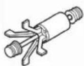
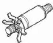
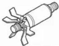
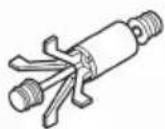
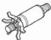
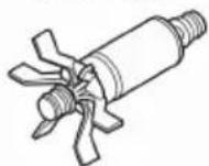
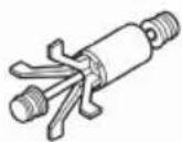
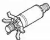
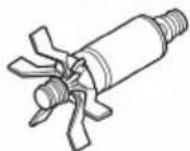
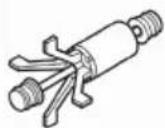
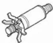
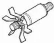
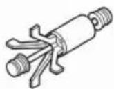
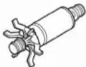
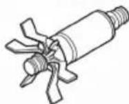
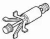
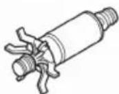
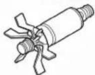
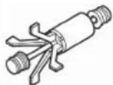
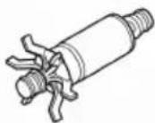
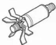
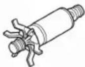
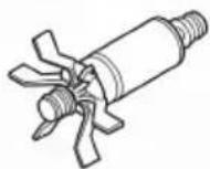
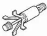
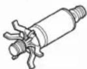
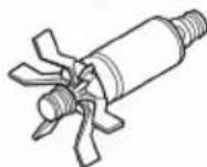
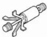
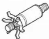
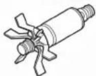
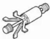
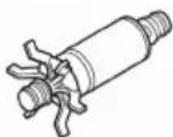
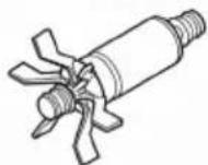
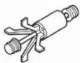
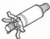
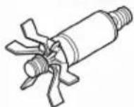
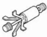
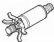
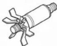
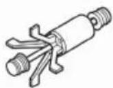
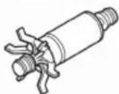
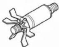
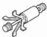
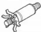
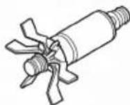
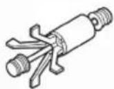
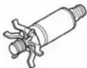
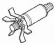
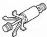
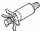
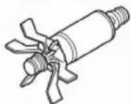
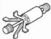
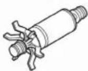
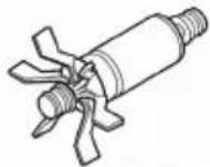
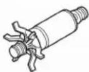
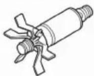
Cleaning/replacing the impeller unit
Prerequisite:
- The unit head is removed. (→ Dismantling the unit head)
- Pull the pump lid off downward.
- EDEN FES 200, 300, EDEN FET 200, 300: Push the tab down.
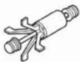
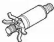
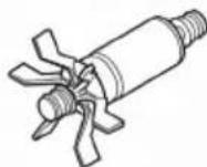
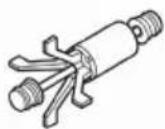
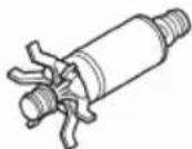
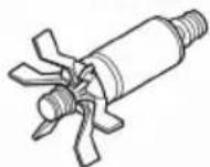
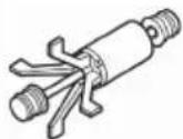
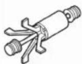
- Remove the impeller unit, clean or replace.
- Reassemble the unit in the reverse order.
- Ensure that the two rubber bearings are correctly seated.
- Ensure that the vent hose is in place and is pointing upwards so that the air can escape.
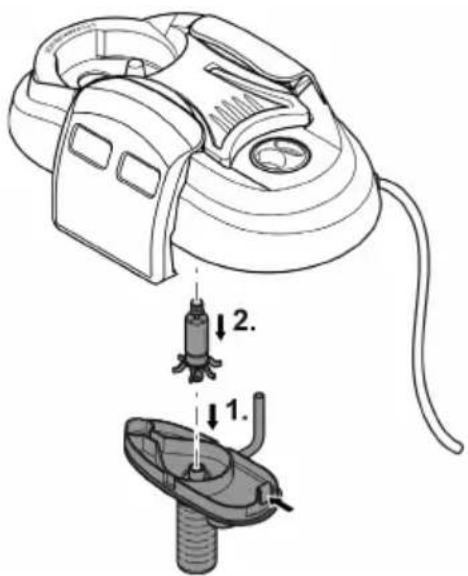
EDEN
FES 100
FET 100
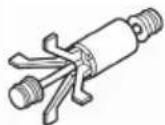
EDEN
FES 200
FET 200
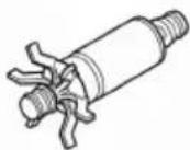
EDEN
FES 300
FET 300
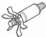
FST0070
Re-installing the unit
- Reassemble the unit head and filter unit. (→ Fitting the unit head)
EN
Malfunction remedy
| Malfunction | Cause | Remedy |
| Unit does not start up. | No mains voltage | Check the mains voltage. |
| Impeller unit blocked | Clean | |
| Excessive height difference between the top edge of the aquarium and the suction unit | Reduce the height difference | |
| Water level in the unit too low | Top up water | |
| Water flow insufficient | Filter housing or impeller unit soiled | Clean |
| Impeller unit worn | Replace the impeller unit. | |
| Flow incorrectly set | Correct the setting. | |
| Foam filter soiled | Clean | |
| Activated carbon soiled | Clean | |
| Ceramic substrate soiled | Clean | |
| Suction basket clogged | Clean suction basket. | |
| Pipework soiled | Clean suction unit, flow-out unit and hoses. | |
| Insufficient filtering performance | Foam filter soiled | Clean |
| Foam filter worn | Replace | |
| Ceramic substrate soiled | Clean | |
| Ceramic substrate worn | Replace | |
| Activated carbon exhausted | Replace | |
| Insufficient water heating (only units with heater) | Heater defective | Replace |
| Heater not calibrated | Calibrate | |
| Water temperature incorrectly set on the heater | Correct the water temperature setting on the heater. | |
| Increased noise | Air in the filter, vent hose on the pump not correctly positioned. | Correct the position of the vent hose |
Wear parts
- Suction cups
- Impeller unit
- Foam filters
- Activated carbon
- Ceramic substrate
Technical data
| Description | EDEN FES, EDEN FET | ||||
| 100 | 200 | 300 | |||
| Rated voltage | V AC | 230 | 230 | 230 | |
| Mains frequency | Hz | 50 | 50 | 50 | |
| Protection type | IPX8 | IPX8 | IPX8 | ||
| Power consumption, filter | W | 11 | 17 | 23 | |
| Power consumption, heater | W | 100 | 200 | 300 | |
| Max. delivery rate | l/h | 600 | 800 | 1000 | |
| Maximum head height | m | 1.1 | 1.1 | 1.3 | |
| Maximum water column | m | 1.8 | 1.8 | 1.8 | |
| Filter volume | l | 1.25 | 4.2 | 6.4 | |
| Pre-filter volume | l | 0.7 | 1.5 | 1.5 | |
| Suitable for aquarium up to max. | l | 100 | 200 | 300 | |
| Length of power connection cable (filter, heater) | m | 1.5 | 1.5 | 1.5 | |
| Hose length | m | 2.5 | 2.5 | 2.5 | |
| Hose diameter for connection to hose sleeves | mm | 13 | 17 | 17 | |
| Dimensions | Length | mm | 200 | 290 | 290 |
| Width | mm | 120 | 180 | 180 | |
| Height | mm | 240 | 330 | 420 | |
| Weight | EDEN FES | kg | 1.8 | 3.7 | 4.4 |
| EDEN FET | kg | 2.1 | 4.0 | 4.8 | |
Disposal
NOTE
Do not dispose of this unit with household waste.
▶ Dispose of the unit by using the return system provided for this purpose.
▶ Should you have questions, please contact your local disposal company. They will give you information on how to correctly dispose of the unit.
▶ Render the unit unusable by cutting the cables.
FST0057
FST0064
FST0063
FST0069
FST0068

PRUDENCE
FST0060
FR
IN
OUT
FST0062
Mise en service
REMARQUE
FST0014
EDEN
FES 100
FET 100
EDEN
FES 200
FET 200
EDEN
FES 300
FET 300
FST0070
| EDEN FES 100, 200, 300EDEN FET 100, 200, 300 | Aantal | |||
| 100 | 200 | 300 | ||
| 1 | Zuignap | 5 | 5 | 5 |
| 2 | Klem | 5 | 5 | 5 |
| 3 | Slangadapter, regelbaar | 2 | 2 | 2 |
| 4 | Bocht | 1 | 1 | 1 |
| 5 | Dopmoer | 4 | 4 | 4 |
| 6 | Adapter aanzuigbuisEDEN FES 100 | EDEN FET 100 | 1 | - | - |
| 7 | Adapter aanzuigbuisEDEN FES 200, 300 | EDEN FET 200, 300 | - | 1 | 1 |
| 8 | Zuigkorf | 1 | 1 | 1 |
| 9 | Afsluitdop | 1 | 1 | 1 |
| 10 | Waterverdeler | 1 | 1 | 1 |
Functiebeschrijving
FST0057
Verwarming naderhand monteren
FST0064
Verwarming monteren
VOORZICHTIG
FST0063
FST0069
Apparaatkop monteren
Zo gaat u te werk:
FST0068

VOORZICHTIG
FST0060
NL
IN
OUT
FST0062
Ingebruikname
OPMERKING
FST0014
Verwarmingseenheid reinigen

VOORZICHTIG
EDEN
FES 100
FET 100
EDEN
FES 200
FET 200
EDEN
FES 300
FET 300
Apparaat weer installeren
- Apparaatkop en filtereenheid weer samenbouwen. (→ Apparaatkop monteren)
Storing verhelpen
| EDEN FES 100, 200, 300EDEN FET 100, 200, 300 | Cantidad | |||
| 100 | 200 | 300 | ||
| 1 | Ventosa | 5 | 5 | 5 |
| 2 | Borne | 5 | 5 | 5 |
| 3 | Adaptador de manguera, regulable | 2 | 2 | 2 |
| 4 | Pieza angular | 1 | 1 | 1 |
| 5 | Tuerca racor | 4 | 4 | 4 |
| 6 | Adaptador tubo de aspiraciónEDEN FES 100 | EDEN FET 100 | 1 | - | - |
| 7 | Adaptador tubo de aspiraciónEDEN FES 200, 300 | EDEN FET 200, 300 | - | 1 | 1 |
| 8 | Cesta de aspiración | 1 | 1 | 1 |
| 9 | Tapa | 1 | 1 | 1 |
| 10 | Distribuidor de agua | 1 | 1 | 1 |
FST0057
FST0064
FST0063
FST0068

CUIDADO
FST0060
ES
IN
OUT
FST0062
Puesta en marcha
INDICACIÓN
FST0014
EDEN
FES 100
FET 100
EDEN
FES 200
FET 200
EDEN
FES 300
FET 300
FST0070
FST0057
FST0064
FST0063
Montar a cabeça
FST0068

CUIDADO!
Posicionar e conectar
FST0060
IN
OUT
PT
FST0062
FST0014
EDEN
FES 100
FET 100
EDEN
FES 200
FET 200
EDEN
FES 300
FET 300
FST0070
Instalar o aparelho
FST0064
FST0063
FST0069
FST0068

ATTENZIONE
FST0060
IN
OUT
FST0062
Messa in funzione
NOTA
FST0014
EDEN
FES 100
FET 100
EDEN
FES 200
FET 200
EDEN
FES 300
FET 300
FST0070
| EDEN FES 100, 200, 300EDEN FET 100, 200, 300 | Antal | |||
| 100 | 200 | 300 | ||
| 1 | Sugekop | 5 | 5 | 5 |
| 2 | Klemme | 5 | 5 | 5 |
| 3 | Slangeadapter, regulerbar | 2 | 2 | 2 |
| 4 | Vinkelstykke | 1 | 1 | 1 |
| 5 | Omløbsmøtrik | 4 | 4 | 4 |
| 6 | Adapter til indsugningsrørEDEN FES 100 | EDEN FET 100 | 1 | - | - |
| 7 | Adapter til indsugningsrørEDEN FES 200, 300 | EDEN FET 200, 300 | - | 1 | 1 |
| 8 | Sugesi | 1 | 1 | 1 |
| 9 | Lukkehætte | 1 | 1 | 1 |
| 10 | Vandfordeler | 1 | 1 | 1 |
DA
FST0057
FST0064
Montering af varmer

FORSIGTIG
FST0069
Montering af apparathoved
Sådan gør du:
DA
FST0068

FORSIGTIG
FST0060
IN
OUT
FST0062
Ibrugtagning
BEMÆRK
FST0014
Rengør varmeenhed

FORSIGTIG
EDEN
FES 100
FET 100
EDEN
FES 200
FET 200
EDEN
FES 300
FET 300
FST0070
Installer apparatet igen
- Sæt apparathoved og filterenhed sammen igen. (→ Montering af apparathoved)
Fejlafhjælpning
| EDEN FES 100, 200, 300EDEN FET 100, 200, 300 | Antall | |||
| 100 | 200 | 300 | ||
| 1 | Sugekopp | 5 | 5 | 5 |
| 2 | Klemme | 5 | 5 | 5 |
| 3 | Slangeadapter, regulerbar | 2 | 2 | 2 |
| 4 | Vinkelstykke | 1 | 1 | 1 |
| 5 | Overfalsmutter | 4 | 4 | 4 |
| 6 | Adapter innsugsrørEDEN FES 100 | EDEN FET 100 | 1 | - | - |
| 7 | Adapter innsugsrørEDEN FES 200, 300 | EDEN FET 200, 300 | - | 1 | 1 |
| 8 | Sugekurv | 1 | 1 | 1 |
| 9 | Lukkehette | 1 | 1 | 1 |
| 10 | Vannfordeler | 1 | 1 | 1 |
NO
FST0057
Ettermontere varmeelement
EDEN FES 100, 200, 300 kan utstyres med varmeelementet EDEN RCA.
EDEN RCA
FST0064
FST0069

FORSIKTIG
FST0060
IN
OUT

FST0062
Igangsetting
MERK
FST0014
EDEN
FES 100
FET 100
EDEN
FES 200
FET 200
EDEN
FES 300
FET 300
FST0070
| EDEN FES 100, 200, 300EDEN FET 100, 200, 300 | Antal | |||
| 100 | 200 | 300 | ||
| 1 | Sugkopp | 5 | 5 | 5 |
| 2 | Klämma | 5 | 5 | 5 |
| 3 | Slangadapter, reglerbar | 2 | 2 | 2 |
| 4 | Vinkelstycke | 1 | 1 | 1 |
| 5 | Överfallsmutter | 4 | 4 | 4 |
| 6 | Adapter insugningsrörEDEN FES 100 | EDEN FET 100 | 1 | - | - |
| 7 | Adapter insugningsrörEDEN FES 200, 300 | EDEN FET 200, 300 | - | 1 | 1 |
| 8 | Sugkorg | 1 | 1 | 1 |
| 9 | Lock | 1 | 1 | 1 |
| 10 | Vattenfördelare | 1 | 1 | 1 |
SV
FST0057
FST0064
Montera värmaren
! OBS
Demontera anslutningsenheten
FST0069
Montera apparatens ovandel
Gör så här:
SV
FST0068

OBS
FST0060
Montera samman utströmmarenheten
Gör så här:
IN
OUT
FST0062
Driftstart
ANVISNING
FST0014
EDEN
FES 100
FET 100
EDEN
FES 200
FET 200
EDEN
FES 300
FET 300
FST0070
Installera apparaten på nytt
FST0064
Lämmittimen asennus
HUOMIO
FST0069
Laitepään asennus
Toimit näin:
HUOMIO
FST0060
IN
OUT
FST0062
Käyttöönotto
OHJE
FST0014
EDEN
FES 100
FET 100
EDEN
FES 200
FET 200
EDEN
FES 300
FET 300
FST0070
HU
FST0057
FST0064
A fűtő beszerelése
VIGYÁZAT
HU
FST0063
FST0069
HU
FST0068

VIGYÁZAT
FST0060
IN
OUT
FST0062
Üzembe helyezés
TUDNIVALÓ:
FST0014
EDEN
FES 100
FET 100
EDEN
FES 200
FET 200
EDEN
FES 300
FET 300
FST0070
FST0057
PL
FST0064
FST0063
PL
FST0069
PL
FST0068

OSTROŻNIE
FST006C
IN
OUT
FST0062
Rozruch
WSKAZÓWKA
FST0014
EDEN
FES 100
FET 100
EDEN
FES 200
FET 200
EDEN
FES 300
FET 300
FST0070
FST0057
Přidání topení
FST0064
Montáž topení
POZOR
FST0063
FST0069
FST0068

POZOR
FST0060
IN
OUT
FST0062
Uvedení do provozu
UPOZORNĚNÍ
FST0014
EDEN
FES 100
FET 100
EDEN
FES 200
FET 200
EDEN
FES 300
FET 300
FST0070
| EDEN FES 100, 200, 300EDEN FET 100, 200, 300 | Počet | |||
| 100 | 200 | 300 | ||
| 1 | Prísavka | 5 | 5 | 5 |
| 2 | Svorka | 5 | 5 | 5 |
| 3 | Adaptér na hadicu, regulovatel'ný | 2 | 2 | 2 |
| 4 | Spojka – koleno | 1 | 1 | 1 |
| 5 | Prevlečná matica | 4 | 4 | 4 |
| 6 | Adaptér na nasávaciu rúrkuEDEN FES 100 | EDEN FET 100 | 1 | - | - |
| 7 | Adaptér na nasávaciu rúrkuEDEN FES 200, 300 | EDEN FET 200, 300 | - | 1 | 1 |
| 8 | Nasávací kôš | 1 | 1 | 1 |
| 9 | Uzatváracia hlavica | 1 | 1 | 1 |
| 10 | Rozvádzač vody | 1 | 1 | 1 |
Popis funkcie
FST0057
FST0064
Montáž ohrievača
POZOR
FST0063
SK
FST0069
FST0068
SK
POZOR
FST0060
IN

OUT
FST0062
EDEN
FES 100
FET 100
EDEN
FES 200
FET 200
EDEN
FES 300
FET 300
FST0070
| EDEN FES 100, 200, 300EDEN FET 100, 200, 300 | Število | |||
| 100 | 200 | 300 | ||
| 1 | Prisesek | 5 | 5 | 5 |
| 2 | Objemka | 5 | 5 | 5 |
| 3 | Adapter cevi, možna regulacija | 2 | 2 | 2 |
| 4 | Kotni kos | 1 | 1 | 1 |
| 5 | Blokirna matica | 4 | 4 | 4 |
| 6 | Adapter sesalne ceviEDEN FES 100 | EDEN FET 100 | 1 | - | - |
| 7 | Adapter sesalne ceviEDEN FES 200, 300 | EDEN FET 200, 300 | - | 1 | 1 |
| 8 | Sesalna košara | 1 | 1 | 1 |
| 9 | Zaporni pokrovček | 1 | 1 | 1 |
| 10 | Razdelilnik vode | 1 | 1 | 1 |
Opis funkcij
FST0057
Dodatno opremljanje grelca
EDEN FES 100, 200, 300 lahko naknadno opremite z grelcem EDEN RCA.
EDEN RCA
FST0064
Vgraditev grelca
PREVIDNO
FST0063
SL
FST0069
FST0068
SL

PREVIDNO
Postavitev in priklop
FST0060
Sestava iztočne enote
IN
OUT
FST0062
Zagon
NASVET
FST0014
EDEN
FES 100
FET 100
EDEN
FES 200
FET 200
EDEN
FES 300
FET 300
FST0070
| EDEN FES 100, 200, 300EDEN FET 100, 200, 300 | Količina | |||
| 100 | 200 | 300 | ||
| 1 | Sisaljka | 5 | 5 | 5 |
| 2 | Stezaljka | 5 | 5 | 5 |
| 3 | Adapter za crijevo, namjestiv | 2 | 2 | 2 |
| 4 | Koljenasti zglob | 1 | 1 | 1 |
| 5 | Natična matica | 4 | 4 | 4 |
| 6 | Adapter usisne cijeviEDEN FES 100 | EDEN FET 100 | 1 | - | - |
| 7 | Adapter usisne cijeviEDEN FES 200, 300 | EDEN FET 200, 300 | - | 1 | 1 |
| 8 | Usisna košara | 1 | 1 | 1 |
| 9 | Zaporni čep | 1 | 1 | 1 |
| 10 | Razdjelnik vode | 1 | 1 | 1 |
Opis rada
FST0057
Naknadno opremanje grijača
EDEN FES 100, 200, 300 možete naknadno opremiti s grijačem EDEN RCA.
EDEN RCA
FST0064
Montaža grijača
OPREZ
FST0063
HR
FST0069
Montiranje glave uređaja
FST0068
HR

OPREZ
FST0060
Sastavljanje izlazne jedinice
IN
OUT
FST0062
Stavljanje u pogon
NAPOMENA
FST0014
EDEN
FES 100
FET 100
EDEN
FES 200
FET 200
EDEN
FES 300
FET 300
FST0070
FST0057
FST0064
! ATENTIE
FST0063
RO
FST0069
FST0068

ATENTIE
FST0060
Asamblati unitatea de evacuare
IN
OUT
FST0062
FST0014
EDEN
FES 100
FET 100
EDEN
FES 200
FET 200
EDEN
FES 300
FET 300
FST0070
FST0057
ВНИМАНИЕ
FST0063
FST0069
FST0068
BG

ВНИМАНИЕ
BG
Монтаж и свързване
FST0060
IN
OUT
FST0062
EDEN
FES 100
FET 100
EDEN
FES 200
FET 200
EDEN
FES 300
FET 300
FST0070
FST0057
FST0064
FST0063
UK
FST0069
FST0068
UK

ОБЕРЕЖНО
UK
FST0060
IN
OUT
FST0062
FST0014
EDEN
FES 100
FET 100
EDEN
FES 200
FET 200
EDEN
FES 300
FET 300
FST0070
FST0057
ОСТОРОЖНО
FST0063
RU
FST0069
FST0068

ОСТОРОЖНО
RU
FST0060
IN
OUT
FST0062
Пуск в эксплуатацию
УКАЗАНИЕ
FST0014

ОСТОРОЖНО
EDEN
FES 100
FET 100
EDEN
FES 200
FET 200
EDEN
FES 300
FET 300
FST0070
| EDEN FES 100, 200, 300EDEN FET 100, 200, 300 | 数量 | |||
| 100 | 200 | 300 | ||
| 1 | 吸盘 | 5 | 5 | 5 |
| 2 | 夹子 | 5 | 5 | 5 |
| 3 | 软管连接器,可调节 | 2 | 2 | 2 |
| 4 | 肘管 | 1 | 1 | 1 |
| 5 | 锁紧螺母 | 4 | 4 | 4 |
| 6 | 吸管转接器EDEN FES 100 | EDEN FET 100 | 1 | — | — |
| 7 | 吸管转接器EDEN FES 200, 300 | EDEN FET 200, 300 | — | 1 | 1 |
| 8 | 吸滤网 | 1 | 1 | 1 |
| 9 | 螺塞 | 1 | 1 | 1 |
| 10 | 配水器 | 1 | 1 | 1 |
功能说明
FST0057
加装加热器
FST0064
安装加热器
小心
加热器的玻璃壳可能会破碎并造成割伤。
FST0063
拆卸连接单元
FST0069
ZH
安装设备头
步骤如下:
FST0068
小心
加热器的玻璃壳可能会破碎并造成割伤。
安装和连接
需要执行的作业的顺序:
FST0060
组装流出单元
步骤如下:
另外,也可以使用配水器代替出水管。
IN
OUT
FST0062
调试
提示
泵不得无水运转。否则会毁坏该泵。
EDEN
FES 100
FET 100
EDEN
FES 200
FET 200
EDEN
FES 300
FET 300
FST0070
重新安装设备
48477 Hörstel | Germany

info@pfg-gmbh.com
www.edensrl.com
- SICHERHEITSHINWEISE
- HEIZER NACHRÜSTEN
- VORSICHT
- GERÄTEKOPF AUSBAUEN
- GERÄTEKOPF EINBAUEN
- HINWEIS
- ELECTRICAL CONNECTION
- SAFE OPERATION
- INTENDED USE
- PRODUCT DESCRIPTION
- OVERVIEW
- FUNCTION DESCRIPTION
- RETROFITTING THE HEATER
- SYMBOLS ON THE UNIT
- ACCESSING THE UNIT REMOVING THE HEATER
- CAUTION
- FITTING THE HEATER
- HOW TO PROCEED
- REMOVING THE CONNECTION UNIT
- FITTING THE CONNECTION UNIT
- DISMANTLING THE UNIT HEAD
- FITTING THE UNIT HEAD
- PREREQUISITE
- INSTALLATION AND CONNECTION
- ESTABLISHING THE CONNECTIONS
- ASSEMBLING THE SUCTION UNIT
- ASSEMBLING THE FLOW-OUT UNIT
- CONNECTING THE HOSE
- COMMISSIONING/START-UP
- NOTE
- SWITCHING ON/SWITCHING OFF
- MAINTENANCE AND CLEANING
- CLEANING/REPLACING THE FILTER MEDIA
- CLEANING THE HEATER UNIT
- CLEANING/REPLACING THE IMPELLER UNIT
- RE-INSTALLING THE UNIT
- WEAR PARTS
- DISPOSAL
- PRUDENCE
- MISE EN SERVICE
- REMARQUE
- FUNCTIEBESCHRIJVING
- VERWARMING NADERHAND MONTEREN
- VERWARMING MONTEREN
- VOORZICHTIG
- APPARAATKOP MONTEREN
- INGEBRUIKNAME
- OPMERKING
- VERWARMINGSEENHEID REINIGEN
- APPARAAT WEER INSTALLEREN
- CUIDADO
- PUESTA EN MARCHA
- INDICACIÓN
- MONTAR A CABEÇA
- POSICIONAR E CONECTAR
- INSTALAR O APARELHO
- ATTENZIONE
- MESSA IN FUNZIONE
- NOTA
- MONTERING AF VARMER
- FORSIGTIG
- MONTERING AF APPARATHOVED
- SÅDAN GØR DU
- IBRUGTAGNING
- BEMÆRK
- RENGØR VARMEENHED
- INSTALLER APPARATET IGEN
- ETTERMONTERE VARMEELEMENT
- FORSIKTIG
- IGANGSETTING
- MERK
- MONTERA VÄRMAREN
- OBS
- DEMONTERA ANSLUTNINGSENHETEN
- MONTERA APPARATENS OVANDEL
- GÖR SÅ HÄR
- MONTERA SAMMAN UTSTRÖMMARENHETEN
- DRIFTSTART
- ANVISNING
- INSTALLERA APPARATEN PÅ NYTT
- LÄMMITTIMEN ASENNUS
- HUOMIO
- LAITEPÄÄN ASENNUS
- TOIMIT NÄIN
- KÄYTTÖÖNOTTO
- OHJE
- A FŰTŐ BESZERELÉSE
- VIGYÁZAT
- ÜZEMBE HELYEZÉS
- TUDNIVALÓ
- OSTROŻNIE
- ROZRUCH
- WSKAZÓWKA
- PŘIDÁNÍ TOPENÍ
- MONTÁŽ TOPENÍ
- POZOR
- UVEDENÍ DO PROVOZU
- UPOZORNĚNÍ
- POPIS FUNKCIE
- MONTÁŽ OHRIEVAČA
- OPIS FUNKCIJ
- DODATNO OPREMLJANJE GRELCA
- VGRADITEV GRELCA
- PREVIDNO
- POSTAVITEV IN PRIKLOP
- SESTAVA IZTOČNE ENOTE
- ZAGON
- NASVET
- OPIS RADA
- NAKNADNO OPREMANJE GRIJAČA
- MONTAŽA GRIJAČA
- OPREZ
- MONTIRANJE GLAVE UREĐAJA
- SASTAVLJANJE IZLAZNE JEDINICE
- STAVLJANJE U POGON
- NAPOMENA
- ATENTIE
- ASAMBLATI UNITATEA DE EVACUARE
- ВНИМАНИЕ
- МОНТАЖ И СВЪРЗВАНЕ
- ОБЕРЕЖНО
- ОСТОРОЖНО
- ПУСК В ЭКСПЛУАТАЦИЮ
- УКАЗАНИЕ
- 功能说明
- 加装加热器
- 安装加热器
- 小心
- 拆卸连接单元
- 安装设备头
- 安装和连接
- 组装流出单元
- 调试
- 提示
- 重新安装设备
Brand : EDEN
Model : FES 200
Category : Water filter