basic HmIP-SK24 - Thermostat Homematic IP - Free user manual and instructions
Find the device manual for free basic HmIP-SK24 Homematic IP in PDF.


| Product type | Smart radiator thermostat |
| Brand | Homematic IP |
| Model | basic HmIP-SK24 |
| Power supply | 2 LR6/Mignon/AA batteries (1.5 V) |
| Dimensions (W x H x D) | 57 x 68 x 102 mm |
| Protection rating | IP20 |
| Operating temperature | 0 °C to 50 °C |
| Valve type | M30 x 1.5 mm (Danfoss RA adapter included) |
| Valve stroke | 4.3 ± 0.3 mm |
| Adjustment force | > 80 N |
| Radio range | Up to 250 m in free field |
| Radio frequency | 868.0-868.6 MHz / 869.4-869.65 MHz |
| Display | LCD screen |
| Main functions | Manual, automatic, holiday modes, Boost function, weekly programming, command lock, open window detection (with accessory) |
| Package contents | Thermostat, Danfoss RA adapter, support ring, M4 nut, M4 screw, batteries, instruction manual |
| Care and cleaning | Clean with a soft dry cloth, no solvents |
| Safety | Do not open, use only recommended battery type, do not dispose in fire |
| Spare parts and repairability | AA batteries, adapters available; repairs by a professional |
Frequently Asked Questions - basic HmIP-SK24 Homematic IP
User questions about basic HmIP-SK24 Homematic IP
0 question about this device. Answer the ones you know or ask your own.
Ask a new question about this device
Download the instructions for your Thermostat in PDF format for free! Find your manual basic HmIP-SK24 - Homematic IP and take your electronic device back in hand. On this page are published all the documents necessary for the use of your device. basic HmIP-SK24 by Homematic IP.
USER MANUAL basic HmIP-SK24 Homematic IP
Installation and operating manual

text_image
A B C D F E G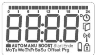
text_image
0 6 12 18 24 8:00:08 AUTOMANU BOOST Start Ende MoTu WeThFrSaSu Offset PrgAbbildung 1
5 Allgemeine
Systeminformationen
natural_image
Line drawing of a hand holding a camera with a blue arrow pointing to the lens (no text or symbols)Abbildung 2
text_image
4 s ↓ ← → ✓Abbildung 3
natural_image
Line drawing of a hand inserting a device into a device (no text or symbols)text_image
Technical diagram of a mechanical gear assembly with numbered components and directional arrows indicating motion or rotation.Abbildung 5
natural_image
Technical line drawing of a mechanical component with a blue arrow pointing to a circular feature (no text or symbols)Abbildung 6
natural_image
Mechanical assembly diagram showing a connector with threaded shaft and screwdriver (no text or labels)Abbildung 7
natural_image
Hand holding a battery pack with blue arrows indicating internal components (no text or symbols)Abbildung 10
1 Package contents......25
2 Information about this manual....25
3 Hazard information 25
4 Function and device overview.... 26
5 General system information 27
6 Start-up....27
6.1 Pairing 27
6.1.1 Direct pairing with a Homematic IP device 27
6.1.2 Pairing with the Access Point 28
6.2 Installation....29
6.2.1 Removing a thermostat....30
6.2.2 Mounting the radiator thermostat 30
6.2.3 Support ring....31
6.2.4 Danfoss RA adapter 31
6.3 Adjustment run.... 31
7 Configuration menu....32
7.1 Manual mode 32
7.2 Automatic mode 33
7.3 Holiday mode 33
7.4 Operating lock 33
7.5 Time and date....34
7.6 Offset temperature....34
7.7 Programming a heating schedule 34
8 Operation 35
9 Changing the batteries ....35
10 Troubleshooting 36
10.1 Weak batteries....36
10.2 Command not confirmed 36
10.3 Duty cycle 36
10.4 Error codes and flashing sequences 37
11 Restoring factory settings 39
12 Maintenance and cleaning 39
13 General information about radio operation 39
14 Disposal.... 40
15 Technical specifications....41
Documentation © 2022 eQ-3 AG, Germany
All rights reserved. Translation from the original version in German. This manual may not be reproduced in any format, either in whole or in part, nor may it be duplicated or edited by electronic, mechanical or chemical means, without the written consent of the publisher.
Typographical and printing errors cannot be excluded. However, the information contained in this manual is reviewed on a regular basis and any necessary corrections will be implemented in the next edition. We accept no liability for technical or typographical errors or the consequences thereof.
All trademarks and industrial property rights are acknowledged.
Changes may be made without prior notice as a result of technical advances.
157367 (web) | Version 1.3 (04/2024)
1 Package contents
1x Radiator Thermostat – Evo
1x Danfoss RA adapter
1x Support ring
1x Nut M4
1x Cylinder head screw M4 x 12 mm
2x 1.5 V LR6/Mignon/AA batteries
1x Operating manual
2 Information about this manual
Please read this manual carefully before operating your Homematic IP components. Keep the manual so you can refer to it at a later date if you need to. If you hand over the device to other persons for use, please hand over this manual as well.
Symbols used:

Important! This indicates a hazard.

Please note. This section contains important additional information!
3 Hazard information

Caution! There is a risk of explosion if the batteries are not replaced correctly. Replace only with the same or equivalent type. Never recharge non-rechargeable batteries. Do not throw the batteries into a fire. Do not expose batteries to excessive heat. Do not short-circuit batteries. Doing so will present a risk of explosion.

Contact with batteries that are dead or damaged can cause skin irritation. Use protective gloves in this case.

Do not open the device. It does not contain any parts that need to be maintained by the user. In the event of an error, please have the device checked by an expert.

For safety and licensing reasons (CE), unauthorised change and/or modification of the device is not permitted.

The device may only be operated in a dry and dust-free environment and must be protected from the effects of moisture, vibrations, solar or other methods of heat radiation, cold and mechanical loads.

The device is not a toy: do not allow children to play with it. Do not leave packaging material lying around. Plastic films/bags, pieces of polystyrene, etc., can be dangerous in the hands of a child.

We accept no liability for damage to property or personal injury caused by improper use or the failure to observe the hazard warnings. In such cases, all warranty claims are void. We accept no liability for any consequential damage.

The device must only be operated within residential buildings.

Using the device for any purpose other than that described in this operating manual does not fall within the scope of intended use and will invalidate any warranty or liability.
4 Function and device overview
The Homematic IP Radiator Thermostat offers time-controlled and demand-based regulation of the room temperature via a heating schedule with individual heating phases. You can directly configure the radiator thermostat on the device and adjust it to suit your needs. Alternatively, you can control the radiator thermostat in connection with a Homematic IP Access Point comfortably via the free smartphone app. In connection with a Homematic IP Window and Door Contact, the temperature is reduced automatically during ventilation. The radiator thermostat fits to all common radiator valves and is easy to mount – without having to drain any water or intervene in the heating system. With the additional boost function, cool rooms can be heated within short times by opening the heating valve.
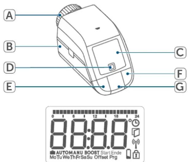
Device overview:
(A) Union nut
(B) Battery compartment (and cover)
(C) Display
(D) System button (pairing button and LED)
(E) Minus button
(F) Plus button
(G) Menu/Boost button
Display overview:
| °C | Setpoint temperature |
| Open window symbol | |
| Empty batteries | |
| Radio transmission | |
| BOOST | Boost function |
| MANU | Manual mode* |
| AUTO | Automatic mode* |
| Holiday mode* | |
| Operating lock* | |
| Overview of heating phases | |
| Time and date* | |
| Offset | Offset temperature* |
| Prg | Programming a heating schedule* |
| Mo Tu We Th Fr Sa Su | Days of the week |
| * (see „7 Configuration menu“ on page 32) | |
text_image
A B C D F E G 0 1 6 12 18 24 88:8.8 AUTOMANU BOOST Start Ende MoTu We Th Fr Sa Su Offset PrgFigure 1
5 General system information
This device is part of the Homematic IP Smart Home system and communicates via the Homematic IP wireless protocol. All devices in the Homematic IP system can be configured easily and individually with a smartphone using the Homematic IP app. Alternatively, you have the option of operating Homematic IP devices via the CCU3 or in conjunction with many partner solutions. The available functions provided by the system in combination with other components are described in the Homematic IP User Guide. All current technical documents and updates can be found at www.homematic-ip.com.
6 Start-up
6.1 Pairing

Please read this entire section before starting the pairing procedure.
You can either pair the radiator thermostat directly with one or more Homematic IP devices or add the device to the Homematic IP Access Point (HmIP-HAP). After direct pairing, configuration must be done directly on the device. After pairing with the Access Point, configuration is done via the Homematic IP app.
6.1.1 Direct pairing with a Homematic IP device

You can directly pair the Homematic IP Radiator Thermostat – basic (HmIP-eTRV-B-2) with the Homematic IP Window / Door Contact with magnet (HmIP-SWDM-2) and/or the Homematic IP Wall Thermostat (HmIP-WTH-B-2).

Please make sure you maintain a distance of at least 50 cm between the devices during pairing.

You can cancel the pairing procedure by briefly pressing the system button (D) again. This will be indicated by the device LED (D) lighting up red.
To connect the device with another Homematic IP device, the pairing mode of both devices must be enabled. To do this, proceed as follows:
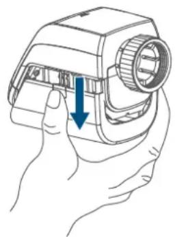
- Open the battery compartment (B) by pulling the battery compartment downwards.
natural_image
Line drawing of a hand holding a camera with a blue arrow pointing to the lens (no text or symbols)Figure 2
- Remove the insulation strip from the battery compartment.
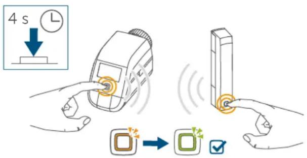
- Press and hold the system button (D) for at least 4 seconds to enable the pairing mode. The device LED (D) starts to flash orange. The pairing mode is active for 3 minutes.
- Press and hold the system button of the device you would like to connect (e.g. the Homematic IP Window / Door Contact with magnet) for at least 4 seconds to enable the pairing mode. The device LED starts to flash orange. For further information, please refer to the operating manual of the corresponding device.
text_image
4 s ↓ ← → ✓Figure 3 The device LED lights up green to indicate that pairing has been successful. If pairing has failed, the device LED lights up red. Please try again.
i If no pairing operations are performed, pairing mode is exited automatically after 3 minutes.
If you would like to add another device to an existing device group, first enable the pairing mode of the existing device in the group and afterwards the pairing mode of the new device.
If you would like to add a wall thermostat to an existing device group including a radiator thermostat and a window and door contact, you first need to pair the wall thermostat with the radiator thermostat. Afterwards, you can pair the wall thermostat with the window and door contact.
If you are using several devices in one room, you should pair all devices with each other.
6.1.2 Pairing with the Access Point
If you have already directly paired the device with another Homematic IP device, you first have to restore the factory settings of the device before you can pair the radiator thermostat with the Homematic IP Access Point or the Central Control Unit CCU3 (see „11 Restoring factory settings“ on page 39).
i First set up your Homematic IP Access Point using the Homematic IP app so that you can use other Homematic IP devices in the system. For further information, please refer to the Access Point operating manual.
For more information on pairing and setting up the wall thermostat using a CCU3, please refer to the WebUI manual on our homepage at www.homematic-ip.com.
The device must first be paired with the Homematic IP Access Point so that it can be integrated into your system and communicate with other Homematic IP devices.
To add the device, proceed as follows:
- Open the Homematic IP app on your smartphone.
- Select the menu item "Pair device".
- Open the battery compartment (B) by pulling the battery compartment cover downwards ( see figure).
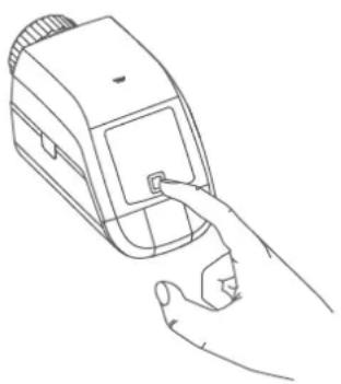
- Remove the insulation strip from the battery compartment. The pairing mode is active for 3 minutes.

You can manually start the pairing mode for another 3 minutes by briefly pressing the system button (D).
natural_image
Line drawing of a hand inserting a digital device into a device (no text or symbols)Figure 4 Your device will automatically appear in the Homematic IP app.
- To confirm, enter the last four digits of the device number (SGTIN) in your app, or scan the QR code. The
device number is on the sticker in the package contents or attached to the device.
- Wait until pairing is completed.
- If pairing was successful, the LED (D) lights up green. The device is now ready for use.
- If the LED lights up red, please try again.
- In the app, give the device a name and allocate it to a room.
6.2 Installation

Please read this entire section before starting the installation.
The Homematic IP Radiator Thermostat is easy to install, and can be done without draining heating water or intervening in the heating system. No special tools are required, nor does the heating have to be switched off.
The union nut (A) attached to the radiator thermostat can be used universally and without accessories for all valves with a thread size of M30 x 1.5 mm from the most popular manufacturers, such as:
- Heimeier
• MNG - Junkers
- Landis&Gyr (Duodyr)
• Honeywell-Braukmann - Oventrop
- Schlösser
- Comap
- Valf Sanayii
- Mertik Maxitrol
- Watts
• Wingenroth (Wiroflex)
• R.B.M
- Tiemme
- Jaga
- Siemens
- Idmar
The device can also be installed on type Danfoss RA (see „6.2.4 Danfoss RA adapter“ on page 31) radiator valves using the enclosed adapter.
6.2.1 Removing a thermostat

In case of visible damage to the existing thermostat, valve or heating pipes, please consult a specialist.
Remove the old thermostatic head from your radiator valve:
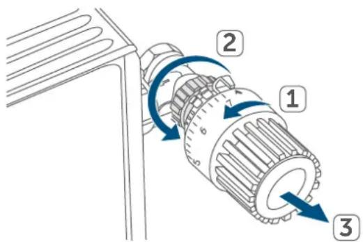
- Rotate the thermostatic head anticlockwise to the maximum value (1). The thermostatic head then no longer presses against the valve spindle, making it easier to remove.
text_image
Technical diagram of a mechanical gear assembly with numbered components and directional arrows indicating motion or flow.Figure 5
The thermostatic head may be held in place in various ways:
- Union nut: Unscrew the union nut in an anticlockwise direction (2). The thermostatic head can then be removed (3).
- Snap-on fastenings: Thermostatic heads that are fastened this way can be detached by turning the fastener/union nut anticlockwise a little. The thermostatic head can then be removed.
- Compression fittings: The thermostatic head is held in place by a mounting ring, which is held together with a screw. Loosen this screw and remove the thermostatic head from the valve.
- Threaded connection with set screw: Loosen the set screw and remove the thermostatic head.
6.2.2 Mounting the radiator thermostat
After removing the old thermostatic head, you can mount the new radiator thermostat on the heating valve:
- Place the radiator thermostat with the metal nut (A) on the heating valve.

If required, you can use one of the supplied adapters for Danfoss valves, (see „6.2.4 Danfoss RA adapter“ on page 31), or the supplied support ring.
6.2.3 Support ring
With some manufacturers' valves, the part of the valve that protrudes into the device has only a small diameter, which causes the radiator thermostat to sit more loosely on the valve. In this case, the provided support ring should be placed into the flange before installing the radiator thermostat. You can then mount the radiator thermostat again as described above.
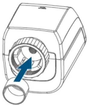
natural_image
Technical line drawing of a mechanical device with a blue arrow pointing to a circular component (no text or symbols)Figure 6
6.2.4 Danfoss RA adapter
The provided adapter is required to attach to Danfoss RA valves.
The RA adapter has been manufactured with pre-tension to provide better fit. Use a screwdriver during installation if necessary and bend the adapter open slightly in the vicinity of the screw.
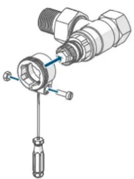
natural_image
Mechanical assembly diagram showing a threaded connector with a screwdriver inserted (no text or symbols present)Figure 7
Danfoss valve bodies have elongated notches around their circumference, which also ensure that the adapter is properly seated when it snaps on.

During installation, please ensure that the pins inside the adapter are lined up with the notches on the valve.

Please be careful not to trap your fingers between the two halves of the adapter!
After clipping onto the valve body, please attach the adapter using the provided screw and nut.
6.3 Adjustment run

When the batteries are inserted, the motor retracts to simplify installation. Meanwhile, "InS" and the activity symbol (n) are displayed.
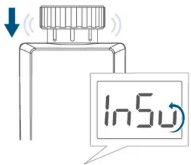
text_image
In5uFigure 8

If the adjustment run was initiated prior to assembly or if an error message is displayed (F1, F2, F3), press the menu/boost button.
After the radiator thermostat has been mounted successfully, an adjustment run (AdA) has to be performed to adapt
the device to the valve. To do this, proceed as follows:
- As soon as "AdA" is displayed, press the menu/boost button (G) to start the adjustment run.
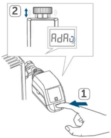
text_image
2 AdRv 1Figure 9
7 Configuration menu
If you operate the device without a Homematic IP Access Point, after start-up you can use the configuration menu to directly select the following modes and adjust the settings to adapt the device to your personal needs:
- Press and hold the menu button (G) to enter the configuration menu.
- Select the desired icon via the plus and minus buttons (E + F) by pressing the menu button briefly to change the settings of the different menu items.

Press and hold the menu button (G) to return to the previous level.
The menu automatically closes without applying changes if there is no operation for more than 1 minute.

If you pair the device with the Homematic IP Access Point, you can easily adjust the settings using the free Homematic IP app.

If you have already adjusted the settings in the configuration menu, or if you have already directly paired the device with another Homematic IP device, you first have to restore the factory settings of the device before you can pair the radiator thermostat with a Homematic IP Access Point or a Central Control Unit CCU3 (see „11 Restoring factory settings“ on page 39).
7.1 Manual mode
In manual mode, the temperature is controlled in accordance with the current temperature set via the push-buttons (E + F). The temperature remains enabled until the next manual change. To enable the manual mode, proceed as follows:
- Press and hold the menu button (G) for approx. 2 seconds to open the configuration menu.
- Select the "Manu" menu item using the plus and minus buttons (E + F).
- Confirm with the menu button.
To confirm, the symbol briefly flashes twice and the device changes back to automatic mode.
7.2 Automatic mode
In automatic mode, the temperature is controlled in accordance with the set heating schedule. Manual changes are enabled until the next point at which the profile changes. Afterwards, the defined heating schedule will be enabled again. To enable automatic mode, proceed as follows:
- Press and hold the menu button (G) for approx. 2 seconds to open the configuration menu.
- Select the "Auto" menu item using the plus and minus buttons (E + F).
- Confirm with the menu button.
To confirm, the symbol briefly flashes twice and the device changes back to automatic mode.
7.3 Holiday mode
If you would like to maintain a constant temperature for a certain period, e.g. during your holidays or a party, the holiday mode can be used. To enable the holiday mode, proceed as follows:
- Press and hold the menu button (G) for approx. 2 seconds to open the configuration menu.
- Select the "Holiday" menu item using the plus or minus buttons (E + F) and confirm with the menu button.
- Use the plus and minus buttons to select the time until which you would like to enable the holiday mode and confirm with the menu button.
- Use the plus and minus buttons to select the date until which you would like to enable the holiday
mode and confirm with the menu button.
- Use the plus and minus buttons to select the temperature for the holiday mode and confirm with the menu button.
To confirm, the symbol briefly flashes twice and the device changes to holiday mode.
7.4 Operating lock
Operation of the device can be locked to avoid settings being changed unintended (e.g. through involuntary touch). To enable or disable the operating lock, proceed as follows:
- Press and hold the menu button (G) for approx. 2 seconds to open the configuration menu.
- Select the "Operating lock" menu item using the plus and minus buttons (E + F).
- Confirm with the menu button.
- Use the plus button to select "On" if you would like to enable the operating lock or "OFF" to disable the operating lock and confirm with the menu button.
To confirm, On or OFF flashes twice and the device changes back to the standard display.
After activating the operating lock, the "lock" symbol is shown in the display. To disable the operating lock, proceed as follows:
- Press and hold the menu button (E) for approx. 2 seconds to open the configuration menu.
- Confirm with the menu button.
- Select "OFF" using the minus button (D) to disable the operating lock.
7.5 Time and date
To set the date and time, please proceed as follows:
- Press and hold the menu button (G) for approx. 2 seconds to open the configuration menu.
- Select the "Date/time" menu item using the plus and minus buttons (E + F).
- Confirm with the menu button.
- Select the desired year using the plus and minus buttons and confirm with the menu button.
- Select the desired month using the plus and minus buttons and confirm with the menu button.
- Select the desired day using the plus and minus buttons and confirm with the menu button.
- Select the desired hours using the plus and minus buttons and confirm with the menu button.
- Select the desired minutes using the plus and minus buttons and confirm with the menu button.
To confirm, the time flashes twice, and the device changes back to the standard display.
7.6 Offset temperature
As the temperature is measured on the wall thermostat, the temperature distribution can vary throughout a room. You can set a temperature offset of ±3.5^ to adjust this. If, for example, 18^ is measured instead of the 20^ set, an offset of -2.0^ must be set. An offset temperature of 0.0^ is set in the factory settings. To adjust the offset temperature, please proceed as follows:
- Press and hold the menu button (G) for approx. 2 seconds to open the configuration menu.
- Select the "Offset" menu item using the plus and minus buttons (E + F).
- Confirm with the menu button.
- Select the desired offset temperature using the plus and minus buttons and confirm with the menu button.
To confirm, the temperature flashes twice and the device changes back to the standard display.
7.7 Programming a heating schedule
In this menu item, you can create a heating schedule with six heating and cooling phases (13 change settings) according to your personal needs:
- Press and hold the menu button (G) for approx. 2 seconds to open the configuration menu.
- Select the "Prg" menu item using the plus or minus buttons (E + F) and confirm with the menu button.
- Under the menu item "DAY", use the plus and minus buttons to select individual weekdays, all weekdays, the weekend or the entire week for your heating schedule and confirm with the menu button.
- Confirm the start time 00:00 hours with the menu button.
- Select the desired temperature and start time using the plus and mi-
nus buttons and confirm with the menu button.
- The next time is shown in the display. You can adjust this time using the plus and minus buttons.
- Select the desired temperature for the next time period using the plus and minus buttons and confirm with the menu button.
- Repeat this procedure until temperatures are stored for the entire period between 0:00 and 23:59 h.
To confirm, the time flashes twice, and the device changes back to the standard display.
8 Operation
After configuration, simple operations are available directly on the device.

If the radiator thermostat is in standby mode, please press the system button (D) once before operation to activate the device.
- Temperature: Press the left (E) or right (F) push-button to manually change the temperature of the radiator. In automatic mode, the manually set temperature will remain the same until the next point at which the schedule changes. Afterwards, the defined heating schedule will be enabled again. During manual mode, the temperature remains activated until the next manual change.
- Boost function: Briefly press the boost button (G) to enable the boost function for heating up the radiator quickly and briefly by
opening the valve. There will be a pleasant room temperature right away because of the radiated heat.
9 Changing the batteries
If the symbol for empty batteries (☐) appears in the display or in the app, please replace the used batteries with two new LR6/Mignon/AA batteries. You must observe the correct battery polarity.
To insert new batteries, proceed as follows:
- Open the battery compartment (B) by pulling the battery compartment cover downwards ( see figure).
- Remove the batteries.
- Insert two new 1.5 V LR6/Mignon/AA batteries into the battery compartment, making sure that you insert them the right way round.

natural_image
Hand holding a battery pack with blue arrows indicating direction of movement (no text or symbols)Figure 10
- After inserting the batteries, pay attention to the flashing sequences of the LED (see „10.4 Error codes and flashing sequences“ on page 37).
Once the batteries have been inserted, the radiator thermostat will perform a self-test and an adjustment run, if required (approx. 2 seconds). Afterwards, initialisation is carried out. The LED test display will indicate that initialisation is complete by lighting up orange and green.
10 Troubleshooting
10.1 Weak batteries
Provided that the voltage value permits it, the radiator thermostat will remain ready for operation even if the battery voltage is low. Depending on the particular load, it may be possible to send transmissions again repeatedly once the batteries have been allowed a brief recovery period.
If the voltage drops too far during transmission, the empty battery symbol (☐) and the corresponding error code will be displayed on the device, (see „10.4 Error codes and flashing sequences“ on page 37). In this case, replace the empty batteries with two new ones (see „9 Changing the batteries“ on page 35).
10.2 Command not confirmed
If at least one receiver does not confirm a command, the LED (D) lights up red at the end of the failed transmission process. The reason for the failed transmission may be radio interference, (see „13 General information about radio operation“ on page 39). This may be caused by the following:
- Receiver cannot be reached.
- Receiver is unable to execute the
command (load failure, mechanical blockade, etc.).
- Receiver is faulty.
10.3 Duty cycle
The duty cycle is a legally regulated limit of the transmission time of devices in the 868 MHz range. The aim of this regulation is to safeguard the operation of all devices working in the 868 MHz range.
In the 868 MHz frequency range we use, the maximum transmission time of any device is 1% of an hour (i.e. 36 seconds in an hour). Devices must cease transmission when they reach the 1% limit until this time restriction comes to an end. Homematic IP devices are designed and produced with 100% conformity to this regulation.
During normal operation, the duty cycle is not usually reached. However, repeated and radio-intensive pairing processes mean that it may be reached in isolated instances during start-up or initial installation of a system. If the duty cycle is exceeded, this is indicated by three slow flashes of the device LED, and may manifest itself in the device temporarily working incorrectly. The device starts working correctly again after a short period (max. 1 hour).
10.4 Error codes and flashing sequences
| Flashing code / LC display | Meaning Solution | |
| F1 Valve drive sluggish | Please check whether the valve pin is stuck. | |
| F2 | Adjustment range too large | Please check the fastening of the radiator thermostat |
| F3 | Adjustment range too small | Please check whether the valve pin is stuck. |
| Battery symbol (a) Battery voltage low | Replace the device batteries (see „9 Changing the batteries“ on page 35). | |
| Battery symbol (a) and --- | Valve moved to error position* | Replace the device batteries (see „9 Changing the batteries“ on page 35). |
| *If empty batteries are not replaced, the radiator thermostat moves to a “valve error position”. This avoids a situation where the set temperature in the room cannot be reached any more due to a low battery. A valve error position of 15% is set in the factory settings. | ||
| Antenna symbol (ψ) flashes | Communication problem with Homematic IP Access Point or connected device | Please check the connection with the Homematic IPAccess Point or the connected devices. |
| Lock symbol (π) Operating lock enabled | Disable the operating lock via the app. | |
| Short orange flashes | Radio transmission/attempting to transmit/configuration data is transmitted | Wait until the transmission is completed. |
| 1x long green flash Transmission confirmed | You can continue operation. | |
| 1x long red flash | Transmission failed or duty cycle limit reached | Please try again (see „10.2 Command not confirmed“ on page 36) or (see „10.3 Duty cycle“ on page 36). |
| Brief steady orange light (after green or red confirmation) | Batteries empty | Replace the batteries (see „9 Changing the batteries“ on page 35). |
| Short orange flashes (every 10 s) | Pairing mode active | Enter the last four digits of the device serial number to confirm (see „6.1.2 Anlernen an den Access Point“ on page 7). |
| Fast orange flashing | Direct pairing mode active | Enable the pairing mode of the device you would like to add (see „6.1.1 Direct pairing with a Homematic IP device“ on page 27). |
| 6x long red flashes Device de | defective | Please see your app for error message or contact your retailer. |
| 1x orange and 1x green light (after inserting batteries) | Test display | You can continue once the test display has stopped. |
| Alternating long and short orange flashing | Device software updating (OTAU) | Wait until the update is completed. |
11 Restoring factory settings

The factory settings of the device can be restored. If you do this, you will lose all your settings.
To restore the factory settings of the wall thermostat, please proceed as follows:
- Open the battery compartment (B) by pulling the battery compartment cover downwards ( see figure).
- Remove one battery.
- Re-insert the battery, making sure that it is right way around, while pressing the system button (D) at the same time. Press and hold the system button until the device LED (D) starts to quickly flash orange.
- Release the system button briefly and then press and hold the system button again until the orange flashing changes to a green lighting.
- Release the system button to conclude the procedure.
The device will perform a restart.
12 Maintenance and cleaning

The device does not require you to carry out any maintenance other than replacing the battery when necessary. Leave any maintenance or repair to a specialist.
Clean the device using a soft, clean, dry and lint-free cloth. You may dampen the cloth a little with lukewarm water to remove more stubborn marks. Do not use any detergents containing solvents, as they could corrode the plastic housing and label.
13 General information about radio operation
Radio transmission is performed on a non-exclusive transmission path, which means that there is a possibility of interference occurring. Interference can also be caused by switching operations, electrical motors or defective electrical devices.

The transmission range within buildings can differ significantly from that available in open space. Besides the transmitting power and the reception characteristics of the receiver, environmental factors such as humidity in the vicinity play an important role, as do on-site structural/screening conditions.
eQ-3 AG, Maiburger Strasse 29, 26789 Leer, Germany, hereby declares that the radio equipment type Homematic IP HmlP-eTRV-B-2 is compliant with Directive 2014/53/EU. The full text of the EU declaration of conformity is available at the following internet address:
www.homematic-ip.com
14 Disposal
Instructions for disposal

This symbol means that the device and the batteries or accumulators must not be disposed of with household waste, the residual waste bin or the yellow bin or yellow bag. For the protection of health and the environment, you must take the product, all electronic parts included in the scope of delivery, and the batteries to a municipal collection point for old electrical and electronic equipment to ensure their correct disposal. Distributors of electrical and electronic equipment or batteries must also take back obsolete equipment or batteries free of charge. By disposing of it separately, you are making a valuable contribution to the reuse, recycling and other methods of recovery of old devices and old batteries. You must separate any old batteries and accumulators of old electrical and electronic devices from the old device if they are not enclosed by the old device before handing it over to a collection point and to dispose of them separately at the local collection points. Please also remember that you, the end user, are responsible for deleting personal data on any old electrical and electronic equipment before disposing of it.
Information about conformity

The CE mark is a free trademark that is intended exclusively for the authorities and does not imply any assurance or guarantee of properties.

For technical support, please contact your retailer.
15 Technical specifications
Device short description: HmIP-eTRV-B-2
Supply voltage: 2x 1.5 V LR6/Mignon/AA
Current consumption: 100 mA max.
Battery life: 2 years (typical)
Protection rating: IP20
Pollution degree: 2
Ambient temperature: 0 to 50°C
Dimensions (W x H x D): 57 x 68 x 102 mm
Weight: 185 g (including batteries)
Radio frequency band: 868.0 – 868.6 MHz 869.4 – 869.65 MHz
Max. radio transmission power: 10 dBm
Receiver category: SRD category 2
Typical range in open space: 250 m
Software class: Class A
Method of operation: Type 1
Connection: M30 x 1.5 mm
Controlling torque: > 80 N
Valve travel: 4.3 ± 0.3 mm
Maximum travel position: 14.3 ± 0.3 mm
Minimum travel position: 10.0 ± 0.3 mm
Subject to modifications.
Table des matières
natural_image
Line drawing of a hand holding a projector with a blue arrow indicating the handle (no text or symbols present)Figure 2
text_image
4 s ↓ ← → ✓Figure 3
natural_image
Line drawing of a hand inserting a device into a device (no text or symbols)Figure 4
text_image
Technical diagram of a mechanical gear assembly with numbered components and directional arrows indicating motion or flow.Figure 5
natural_image
Technical line drawing of a mechanical device with a blue arrow pointing to a circular component (no text or symbols)Figure 6
natural_image
Mechanical assembly diagram showing a threaded connector with a screwdriver inserted (no text or labels)Figure 7
natural_image
Hand holding a battery pack with arrows indicating internal components (no text or symbols)Figure 10
Poids : 185 g (piles comprises)
natural_image
Line drawing of a hand holding a device with a blue arrow pointing to the handle (no text or symbols)Figura 2
text_image
4 s ↓ L □ → □ ✓Figura 3
natural_image
Line drawing of a hand inserting a small object into a device (no text or symbols)Figura 4
text_image
Technical diagram of a mechanical gear assembly with numbered components and directional arrows indicating motion or flow.Figura 5
natural_image
Technical line drawing of a mechanical device with a blue arrow pointing to a circular component (no text or symbols)Figura 6
6.2.4 Adaptadores para Danfoss RA
natural_image
Mechanical assembly diagram showing a threaded connector with a screwdriver inserted (no text or symbols present)Figura 7
natural_image
Hand holding a battery pack with arrows indicating internal components (no text or symbols)Figura 10
natural_image
Line drawing of a hand holding a handheld device with a blue arrow pointing to the handle (no text or symbols)Figura 2
text_image
4 s L → □ → □ ✓Figura 3
natural_image
Line drawing of a hand holding a medical device with a button (no text or symbols)Figura 4
text_image
Technical diagram of a mechanical gear assembly with numbered components and directional arrows indicating rotation or movement.Figura 5
natural_image
Technical line drawing of a mechanical device with a blue arrow pointing to a circular component (no text or symbols)Figura 6
natural_image
Mechanical assembly diagram showing a connector with threaded shaft and screwdriver (no text or labels)Figura 7
natural_image
Hand holding a battery pack with blue arrows indicating direction of movement (no text or symbols)Figura 10
text_image
A B C D F E G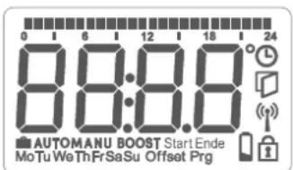
text_image
0 1 6 12 18 24 8:00:8 AUTOMANU BOOST Start Ende MoTu WeThFrSaSu Offset Prgnatural_image
Line drawing of a hand holding a camera with a blue arrow pointing to the lens (no text or symbols)Afbeelding 2
text_image
4 s ↓ ← → ✓Afbeelding 3
natural_image
Line drawing of a hand inserting a device into a device (no text or symbols)text_image
Technical diagram of a mechanical gear assembly with numbered components and directional arrows indicating rotation or movement.Afbeelding 4
natural_image
Technical line drawing of a mechanical device with a blue arrow pointing to a circular component (no text or symbols)Afbeelding 5
natural_image
Mechanical assembly diagram showing a threaded connector with a screwdriver inserted (no text or symbols present)Afbeelding 6
natural_image
Hand holding a battery pack with arrows indicating internal components (no text or symbols)Afbeelding 9
Free download of the Homematic IPapp!

text_image
Blue QR code image, scannable for digital content retrieval
Download on the
App Store

text_image
Blue QR code image, scannable for digital content retrieval
GET IT ON
Google Play
Bevollmächtigter des Herstellers: Manufacturer's authorised representative

eQ-3 AG
Maiburger Straße 29
26789 Leer / GERMANY
www.eQ-3.de