PSS-640 - Projector wall mount SONY - Free user manual and instructions
Find the device manual for free PSS-640 SONY in PDF.

| Product Type | Wall Mount for Projector |
| Brand | Sony |
| Model | PSS-640 |
| Weight | Approximately 4.8 kg (10 lb 9 oz) |
| Maximum Load | 10 kg (22 lb 1 oz) |
| Horizontal Distance Adjustment Range | 280 mm - 690 mm (11 1/32 - 27 5/32 inches) |
| Adjustable Angle (Vertical Tilt) | ± 5° |
| Adjustable Angle (Horizontal Rotation) | ± 5° |
| Adjustable Angle (Horizontal Roll) | ± 5° |
| Arm Attachment Methods | Method A (Y=370-690 mm) or Method B (Y=280-600 mm) |
| Supplied Accessories | Mounting Plate, Wall Plate Template, Wall Plate Cover, Anchor Bolts 11×50 (5), Self-tapping Screws M6×55, Bolts M6×10 mm (4), Bolts M4×10 mm (4), Bolts M5×10 mm (4) |
| Materials | Steel (estimated) |
| Color | Black (estimated) |
| Installation | By authorized Sony dealer or qualified technician only |
| Intended Use | Recommended Sony projectors |
| Maintenance | Check screw tightness every two months |
| Repairability | Do not disassemble or modify; contact an authorized technician |
| Safety Standards | Use of metal cables to prevent swinging |
| Dimensions (Method A, side view) | 370-690 mm (from wall to mounting center) |
| Dimensions (Method B, side view) | 280-600 mm (from wall to mounting center) |
| Warranty | Not specified; contact Sony |
Frequently Asked Questions - PSS-640 SONY
User questions about PSS-640 SONY
0 question about this device. Answer the ones you know or ask your own.
Ask a new question about this device
Download the instructions for your Projector wall mount in PDF format for free! Find your manual PSS-640 - SONY and take your electronic device back in hand. On this page are published all the documents necessary for the use of your device. PSS-640 by SONY.
USER MANUAL PSS-640 SONY
Projector Wall Mount
| 特約店様用取付説明書 | JP |
| Installation manual for Dealers | CB |
| Manuel d'installation destiné aux revendeurs | FR |
| Installationshandbuch für Händler | LS |
| Manual de instalación para proveedores | DE |
| Manuale d'installazione per i rivenditori | IT |
| 经销商用安装说明书 | CS |
Sony Corporation Printed in China
PSS-640
© 2012 Sony Corporation

• BAUART GEPRÜFT • TYPE APPROVED
日本語
ご注意
natural_image
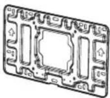
Technical line drawing of a mechanical assembly with mounting flanges and a central rod (no text or symbols)壁用プレート (1)
natural_image
Pure technical diagram of a mechanical component with no text, numbers, or symbols壁用プレートテンプレート
natural_image
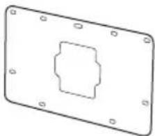
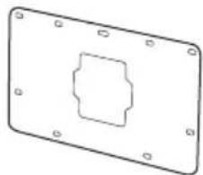
Simple line drawing of a rectangular plate with a central square cutout and corner holes (no text or symbols)壁用プレートカバー (1)
natural_image
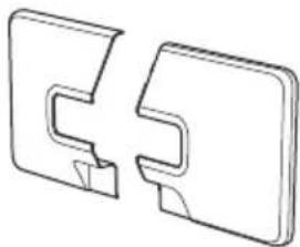
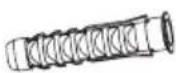
Technical line drawing of two mechanical component parts (no text or symbols)M4 × 10 留め具 (4)

M6 × 10 留め具 (4)

六角レンチ (1)
| VPL-SW536C/SW536/SW526C/SW526/SW535C/SW535/SW525C/SW525/SX536/SX535 | VPL-SW630C/SW620C/SW630/SW620/SX630 |
| 190.0 189.4 |
| VPL-SW536C/SW536/SW526C/SW526/SW535C/SW535/SW525C/SW525/SX536/SX535 | VPL-SW630C/SW620C/SW630/SW620/SX630 |
| 65 77 |
投写距離表
VPL-SW536C/SW536/SW526C/SW526/SW535C/SW535/SW525C/SW525
单位:m
VPL-SW536C/SW536/SW526C/SW526/SW535C/SW535/SW525C/SW525/SX536/SX535
VPL-SW630C/SW620C/SW630/SW620/SX630
natural_image
Technical line drawing of a device with a mounted component and a base, showing no text or symbols.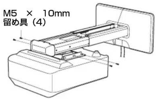
natural_image
Technical illustration of a mechanical device with a magnified inset showing a rotating component (no text or symbols present)垂直方向に傾斜させる

水平方向に旋回させる
水平方向に対して回転させる

flowchart
graph TD
    A["Operating Device"] --> B{Control}
    B -->|A| C["Assembly Unit"]
    B -->|B| D["Product Package"]
    C --> E["Output Box"]
    D --> F["Final Box"]
前後ヘスライドして調整する

仕様
項目 說明
VPL-SW536C/SW536/SW526C/SW526/SW535C/SW535/SW525C/SW525/SX536/SX535
A の方法でアームを固定したとき
This installation manual is for Sony dealers.
This manual shows the correct handling of the projector wall mount and important precautions necessary to prevent accidents. Be sure to read this manual thoroughly and to do the installation work safely. Keep this manual available for future reference.
To Customers
Sufficient expertise is required for installing this projector wall mount. Be sure to subcontract the installation to Sony dealers or licensed contractors and pay special attention to safety during the installation.
To Sony dealers
Sufficient expertise is required for installing this projector wall mount. Be sure to read this manual thoroughly to do the installation work. Sony is not liable for any damage or accident, such as falling, etc., caused by mishandling or improper installation. Please give this manual to the customer after installation.
This projector wall mount is for Sony projectors. Do not mount any projectors other than the recommended Sony projectors.
Maximum load: 10 kg (22 lb 1 oz)
On Safety
Important Safety Instructions
- For safety reasons, check the strength of the wall before installation. If the wall is not strong enough, reinforce it sufficiently before installation.
- Be sure to assemble and attach the projector wall mount in the order indicated. Otherwise the projector may fall, and it may lead to death or serious injury.
-
When you attach the projector wall mount, be sure to attach wires to prevent swinging when a vibration such as an earthquake strikes.
-
PSS-640 is a support kit for the Sony projector wall mount. Do not use the projector wall mount for purposes other than for which it is designed.
- For installation, consult with the dealer of your projector wall mount or qualified Sony personnel.
- After the installation of projector wall mount and projector, check that they are sufficiently secure and safe to use. Ensure that the screws are still tight every two months.
- Do not use the projector wall mount for purposes other than for which it is designed. Do not attach it to the ceiling, floor, or desk.
- Do not install the projector wall mount on a wall subject to vibration or impact.
- Moving the installation location on your own may lead to physical injury. Consult with the dealer of your projector wall mount, qualified Sony personnel, or qualified service personnel.
- Only qualified service personnel (two or more) should carry out installation or dismounting of the projector from the projector wall mount. If the projector is dismounted when hot, serious injury or fire may result from the product toppling over. Be sure that the projector is not hot when dismounting it from the projector wall mount.
- To avoid fire or electric shock, do not install the projector with the projector wall mount in a humid or excessively dusty place.
- When dismounting the projector from the projector wall mount, be sure to unplug the AC power cord and other connecting cables beforehand.
- If you disassemble or modify the projector wall mount, it may lead to injury. Consult with the dealer of your projector wall mount or qualified Sony personnel for inspection or repair.
- If the screws are not fastened securely, the projector may fall and you may get injury.
- Do not perform installation work at an unstable location. Otherwise you may damage your back or the projector may fall, and it may lead to serious injury.
Notes
• Always verify that the unit is operating properly before use. SONY WILL NOT BE LIABLE FOR DAMAGES OF ANY KIND INCLUDING, BUT NOT LIMITED TO, COMPENSATION OR REIMBURSEMENT ON ACCOUNT OF THE LOSS OF PRESENT OR PROSPECTIVE PROFITS DUE TO FAILURE OF THIS UNIT, EITHER DURING THE WARRANTY PERIOD OR AFTER EXPIRATION OF THE WARRANTY, OR FOR ANY OTHER REASON WHATSOEVER.
• SONY WILL NOT BE LIABLE FOR CLAIMS OF ANY KIND MADE BY USERS OF THIS UNIT OR MADE BY THIRD PARTIES.
- SONY WILL NOT BE LIABLE FOR THE TERMINATION OR DISCONTINUATION OF ANY SERVICES RELATED TO THIS UNIT THAT MAY RESULT DUE TO CIRCUMSTANCES OF ANY KIND.
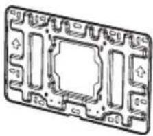
Checking the Supplied Accessories
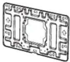
Setting plate (1)
natural_image
Technical line drawing of a mechanical assembly with mounting flanges and a central rod (no text or symbols)Wall plate (1)
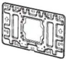
natural_image
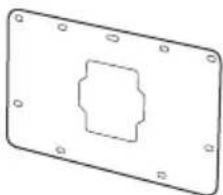
Technical line drawing of a mechanical component with no visible text or symbolsWall plate template

natural_image
Pure technical drawing of a rectangular plate with a central square cutout and mounting holes (no text or symbols)Wall plate cover (1)

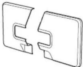
natural_image
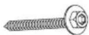
Two 3D mechanical component diagrams showing front and side views (no text or symbols)M4 × 10 fastener (4)

M6 × 10 fastener (4)

Allen key (1)

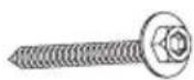
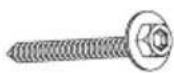
M6 × 55 self-tapping screw (5)

dia.11 × 50 anchor bolt (5)

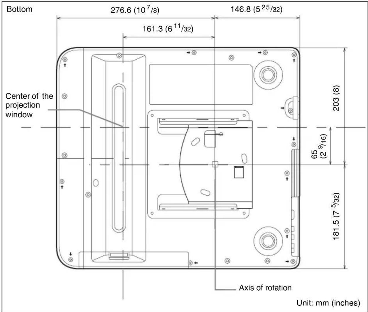
Checking the Installation Position
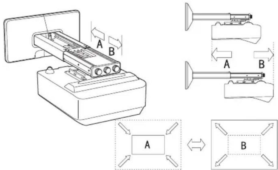
Determining the method to secure the arm
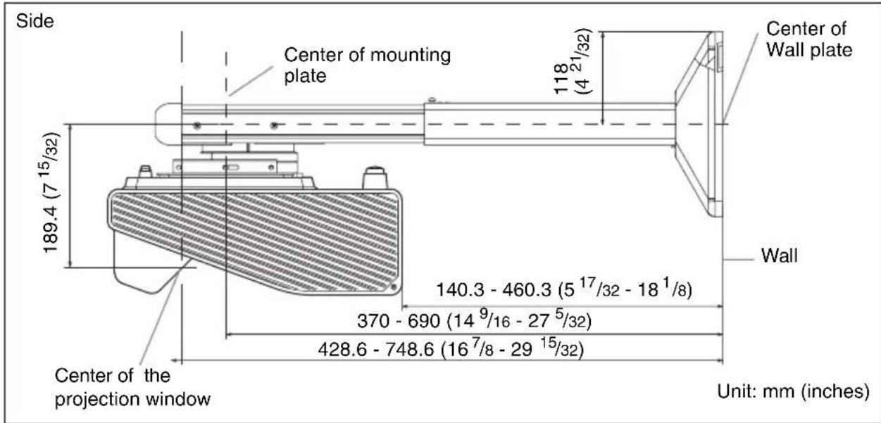
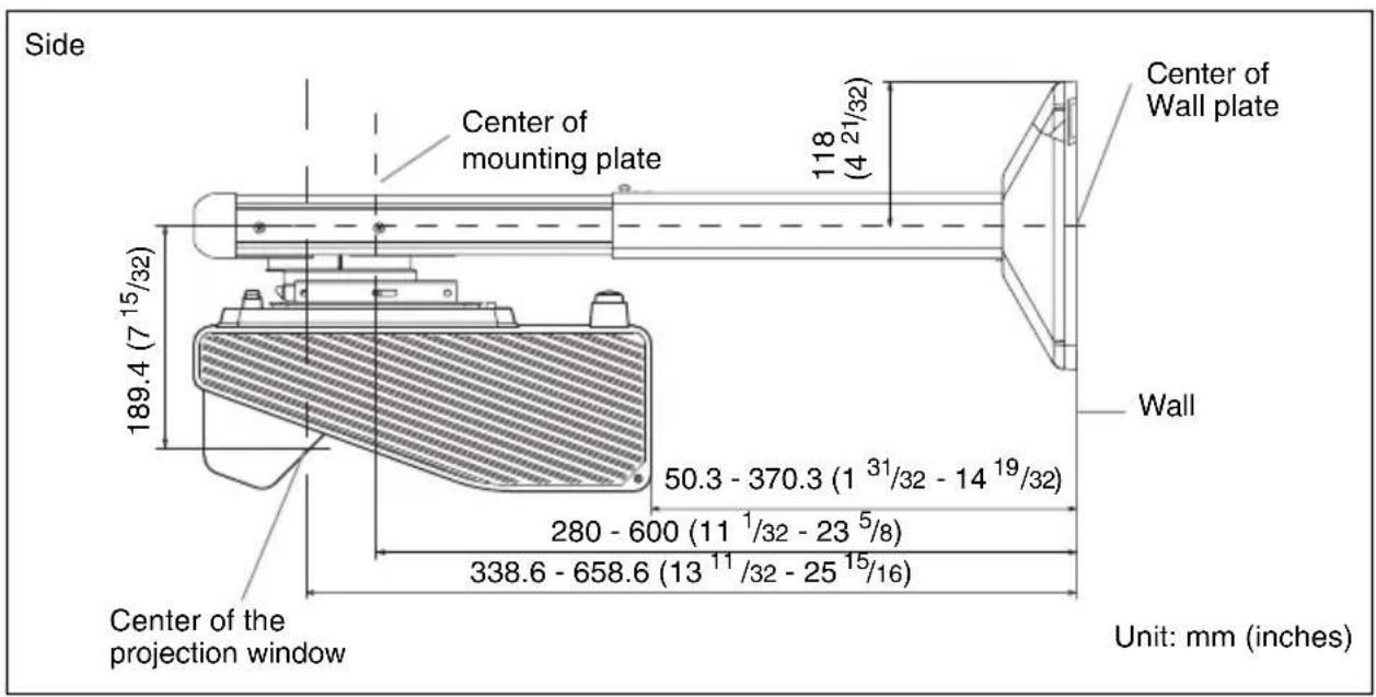
Use method A or B to secure the arm, depending on the distance between the center of projector mounting plate and the wall.
Y = Distance between the center of projector mounting plate and wall
Method A Y=370 mm - 690 mm (14 ^9 / 16 inches - 27 ^5 / 32 inches)
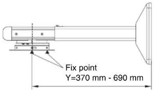
Method B Y=280 mm - 600 mm (11 ^1 / 32 inches - 23 ^5 / 8 inches)
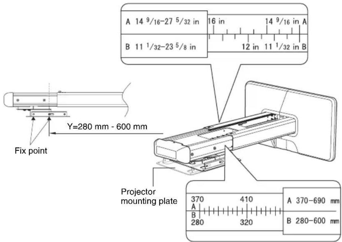
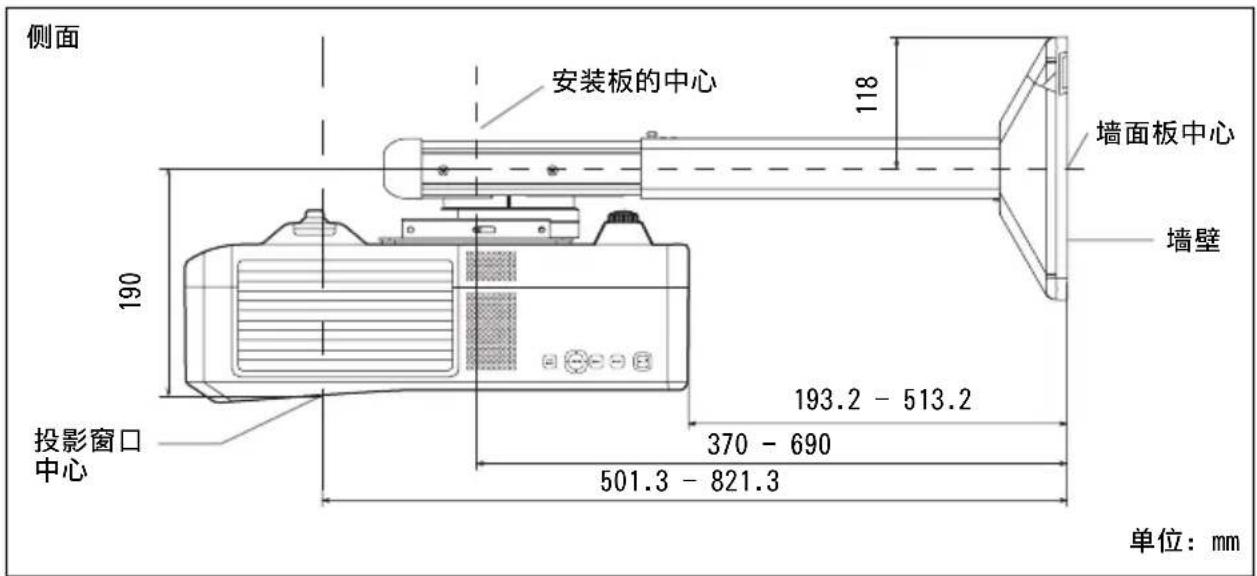
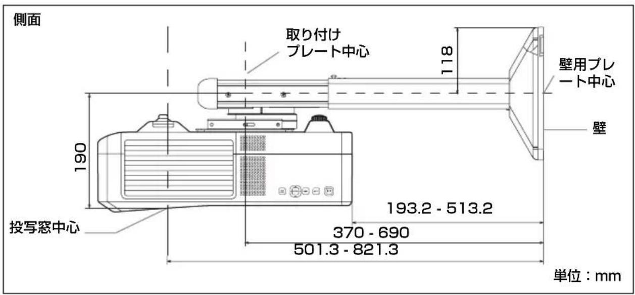
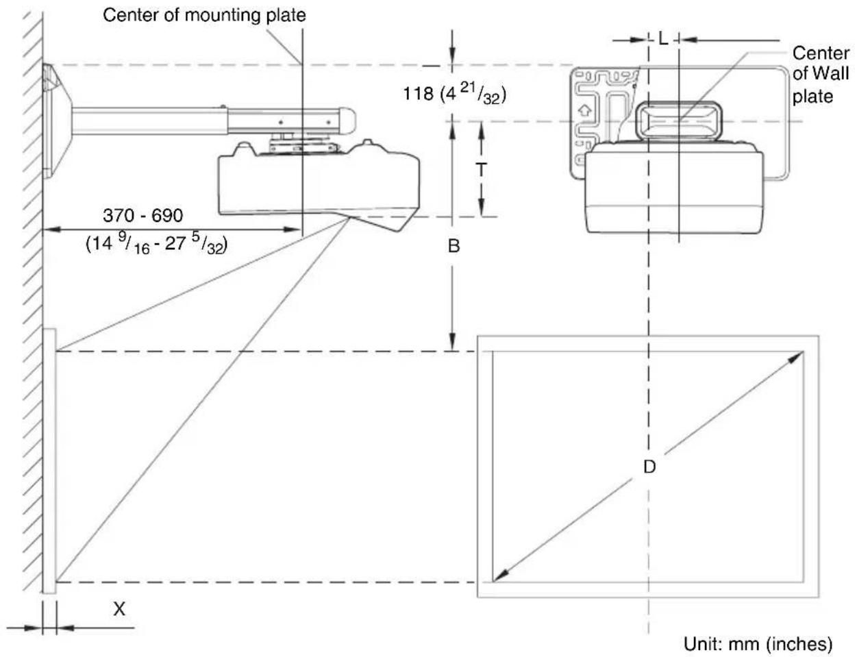
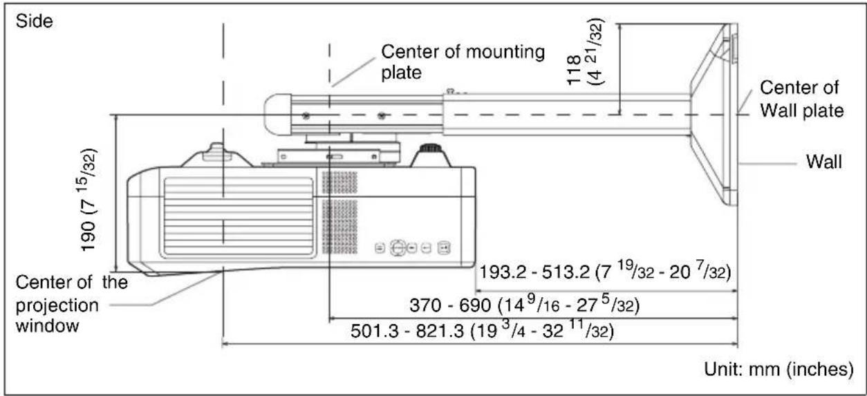
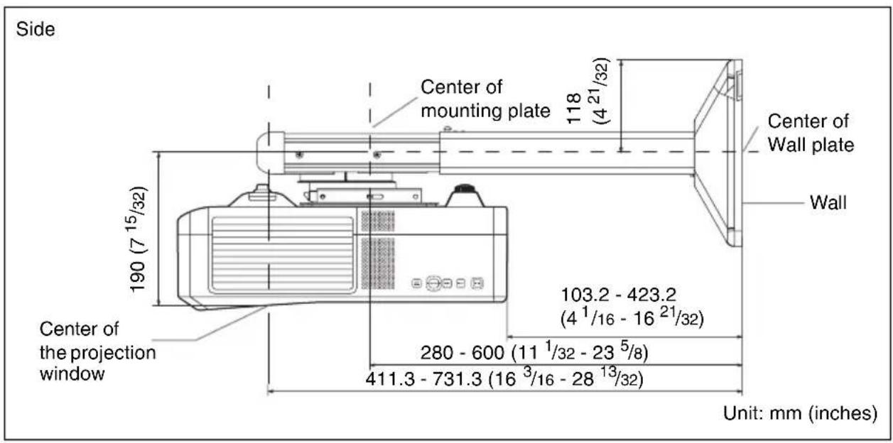
Installation Diagram
While installing the projector wall mount, refer to the projection distance table.
Arm adjustment range: 0 mm - 320 mm (0 inch - 12 ^19 / _32 inches) (arm securing method [A] or [B])
D: Projected image size (Diagonal)
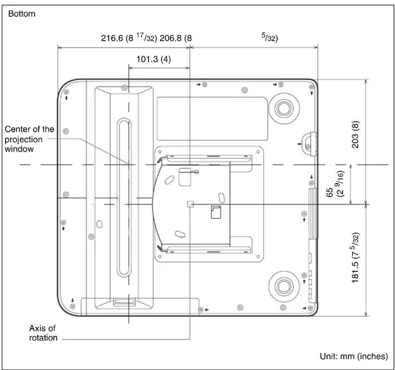
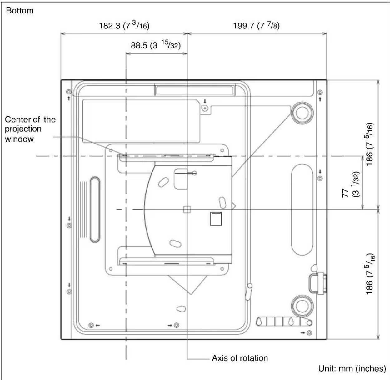
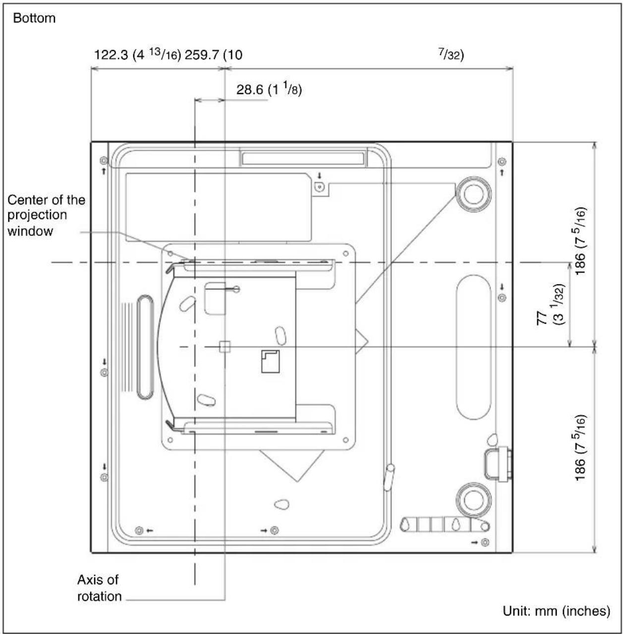
T: Vertical distance from the center of the wall plate to the center of the projection window
L: Horizontal distance from the center of the wall plate to the center of the projection window
X: Distance between projected image and wall
Method A
Method B
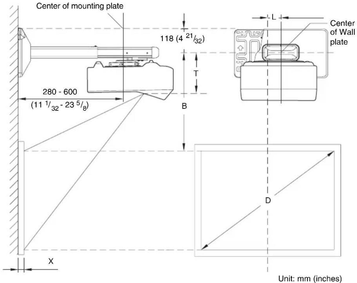
Vertical distance T from the center of the wall plate to the center of the projection window
Unit: mm (inches)
| VPL-SW536C/SW536/SW526C/SW526/SW535C/SW535/SW525C/SW525/SX536/SX535 | VPL-SW630C/SW620C/SW630/SW620/SX630 |
| 190.0 (7 1/2) 189.4 (7 1/2) |
Horizontal distance L from the center of the wall plate to the center of the projection window
Unit: mm (inches)
| VPL-SW536C/SW536/SW526C/SW526/SW535C/SW535/SW525C/SW525/SX536/SX535 | VPL-SW630C/SW620C/SW630/SW620/SX630 |
| 65 (2 5/8) 77 (3 1/8) |
Projection Distance Table
VPL-SW536C/SW536/SW526C/SW526/SW535C/SW535/SW525C/SW525
| Screen Size | Projection Distance Y-X | Height B from wall plate center to edge of screen | |
| Diagonal D Width × Height | |||
| 70 inch(1.78 m) | 1.51 × 0.94(59 × 37) | 0.284-0.296(11 1/4-11 5/8) | 0.328(13) |
| 80 inch(2.03 m) | 1.72 × 1.08(68 × 42) | 0.344-0.358(13 5/8-14) | 0.349(13 3/4) |
| 90 inch(2.29 m) | 1.94 × 1.21(76 × 48) | 0.403-0.419(15 7/8-16 1/2) | 0.369(14 5/8) |
| 100 inch(2.54 m) | 2.15 × 1.35(85 × 53) | 0.462-0.480(18 1/4-18 7/8) | 0.390(15 3/8) |
| 130 inch(3.30 m) | 2.80 × 1.75(110 × 69) | 0.640-0.664(25 1/4-26 1/8) | 0.452(17 7/8) |
Unit: m (inches)
VPL-SX536/SX535
| Screen Size | Projection Distance Y-X | Height B from wall plate center to edge of screen | |
| Diagonal D Width × Height | |||
| 60 inch(1.52 m) | 1.22 × 0.91(48 × 36) | 0.293-0.305(11 5/8-12) | 0.353(14) |
| 70 inch(1.78 m) | 1.42 × 1.07(56 × 42) | 0.364-0.377(14 3/8-14 3/4) | 0.382(15 1/8) |
| 80 inch(2.03 m) | 1.63 × 1.22(64 × 48) | 0.434-0.450(17 1/8-17 5/8) | 0.410(16 1/4) |
| 90 inch(2.29 m) | 1.83 × 1.37(72 × 54) | 0.505-0.523(19 7/8-20 1/2) | 0.439(17 3/8) |
| 110 inch(2.79 m) | 2.24 × 1.68(88 × 66) | 0.646-0.668(25 1/2-26 1/4) | 0.495(19 1/2) |
Unit: m (inches)
VPL-SW630C/SW620C/SW630/SW620
| Screen Size | Projection Distance Y-X | Height B from wall plate center to edge of screen | ||
| Diagonal D Width × Height | Projection Distance Y-X (Min.) | Projection Distance Y-X (Max.) | ||
| 65 inch(1.65 m) | 1.40 × 0.88(55 × 34) | 0.309-0.320(12 1/4 - 12 5/8) | 0.445(17 5/8) | 0.446(17 5/8) |
| 70 inch(1.78 m) | 1.51 × 0.94(59 × 37) | 0.340-0.352(13 1/2-13 7/8) | 0.466(18 3/8) | 0.467(18 1/2) |
| 80 inch(2.03 m) | 1.72 × 1.08(68 × 42) | 0.403-0.417(15 7/8-16 1/2) | 0.509(20 1/8) | 0.510(20 1/8) |
| 90 inch(2.29 m) | 1.94 × 1.21(76 × 48) | 0.466-0.482(18 3/8-19) | 0.551(21 3/4) | 0.552(21 3/4) |
| 100 inch(2.54 m) | 2.15 × 1.35(85 × 53) | 0.529-0.547(20 7/8-21 5/8) | 0.593(23 3/8) | 0.595(23 1/2) |
| 110 inch(2.79 m) | 2.37 × 1.48(93 × 58) | 0.592-0.612(23 3/8-24 1/8) | 0.636(25 1/8) | 0.637(25 1/8) |
Unit: m (inches)
VPL-SX630
| Screen Size | Projection Distance Y-X | Height B from wall plate center to edge of screen | ||
| Diagonal D Width × Height | Projection Distance Y-X (Min.) | Projection Distance Y-X (Max.) | ||
| 70 inch(1.78 m) | 1.42 × 1.07(56 × 42) | 0.315-0.327(12 1/2-12 7/8) | 0.362(14 3/8) | 0.362(14 3/8) |
| 80 inch(2.03 m) | 1.63 × 1.22(64 × 48) | 0.375-0.388(14 7/8-15 3/8) | 0.389(15 3/8) | 0.390(15 3/8) |
| 90 inch(2.29 m) | 1.83 × 1.37(72 × 54) | 0.434-0.449(17 1/8-17 3/4) | 0.417(16 1/2) | 0.417(16 1/2) |
| 100 inch(2.54 m) | 2.03 × 1.52(80 × 60) | 0.494-0.510(19 1/2-20 1/8) | 0.444(17 1/2) | 0.445(17 5/8) |
| 110 inch(2.79 m) | 2.24 × 1.68(88 × 66) | 0.553-0.571(21 7/8-22 1/2) | 0.472(18 5/8) | 0.472(18 5/8) |
| 115 inch(2.92 m) | 2.34 × 1.75(92 × 69) | 0.583-0.602(23-23 3/4) | 0.485(19 1/8) | 0.486(19 1/4) |
Unit: m (inches)
Installation Procedures
To set the projector wall mount on the wall
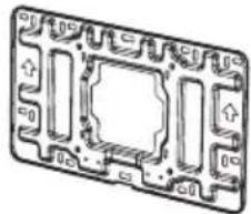
1 Install the wall plate on the wall.
Use M6 × 55 self-tapping screws and dia.11 × 50 anchor bolts for the installation.
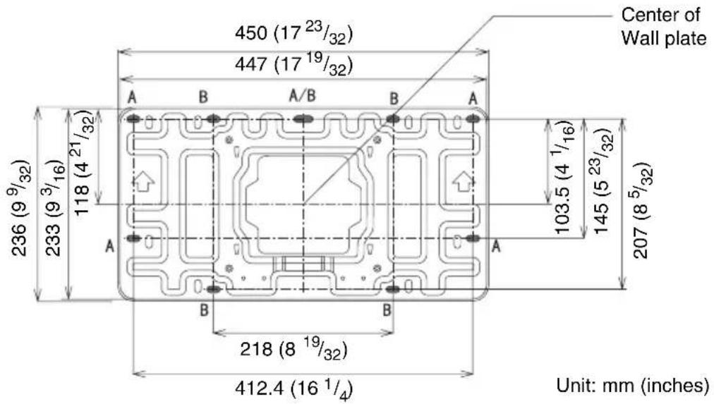
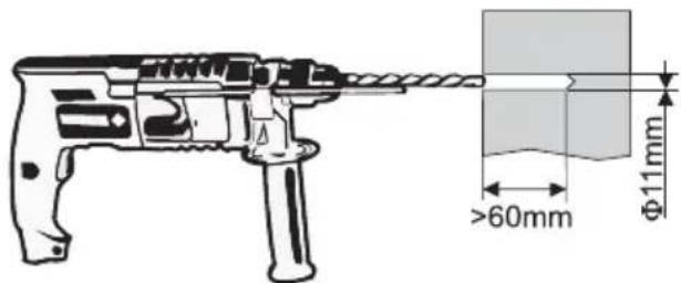
If installing the wall plate on the wall using securing 5 positions, drill the holes indicated by A or B using 11mm . (You can use the supplied wall plate template to determine the position of the holes.) After drilling the holes, insert a 11× 50 anchor bolt into each hole and secure the wall plate with M6× 55 self-tapping screws. Make sure the arrows on the wall plate point upward, and it is kept level.
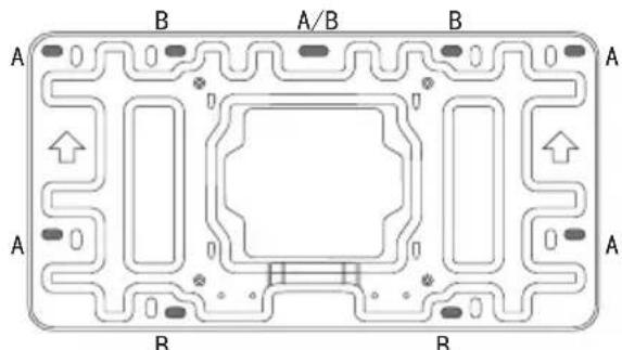
Securing 5 positions
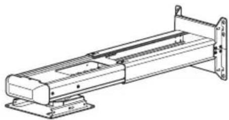
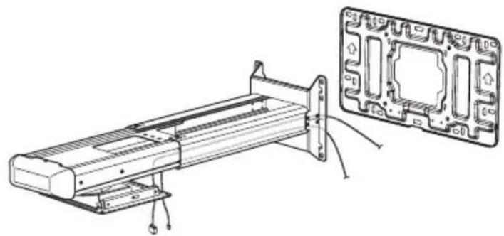
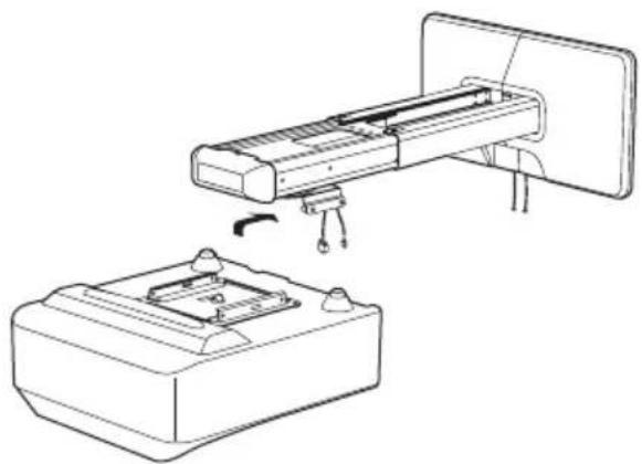
2 Thread the necessary cables in the projector wall mount.
After thread the cables in the projector wall mount, hook the setting plate on the wall plate. Then fix them together using fasteners (4). As shown below.
natural_image
Technical line drawing of a mechanical assembly with a close-up inset showing internal components (no text or symbols)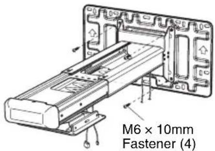
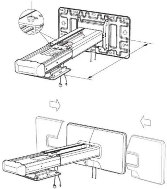
3 Adjust the arm length and attach the wall plate cover.
Adjustment fasteners (M4)
Computer Cables
To install the projector on the projector wall mount
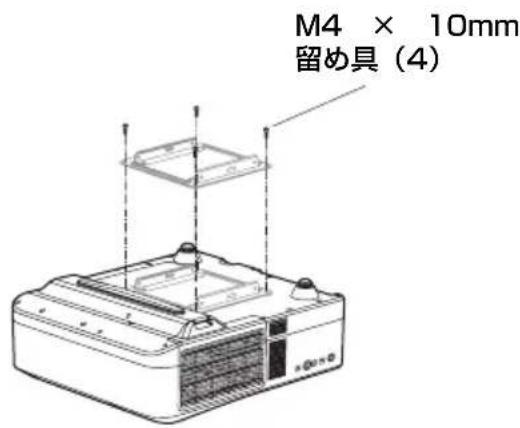
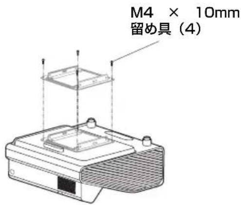
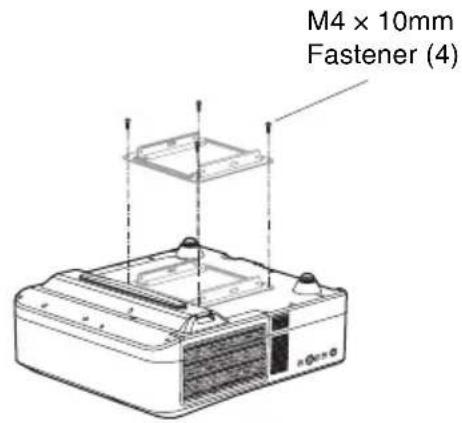
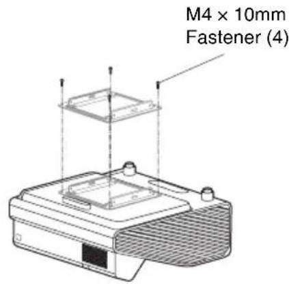
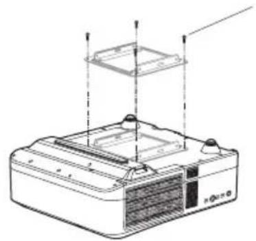
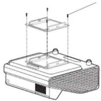
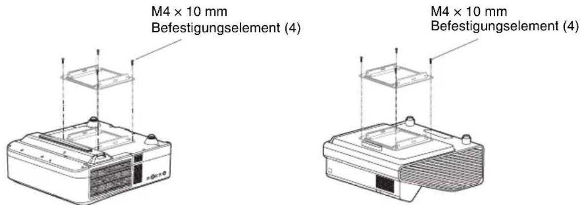
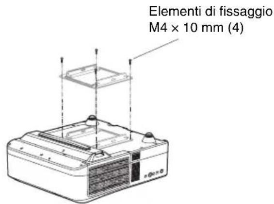
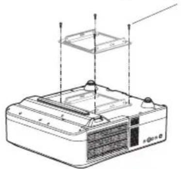
1 Attach the mounting plate to the projector using M4 × 10mm fasteners (4).
VPL-SW536C/SW536/SW526C/SW526/SW535C/SW535/SW525C/SW525/SX536/SX535
VPL-SW630C/SW620C/SW630/SW620/SX630
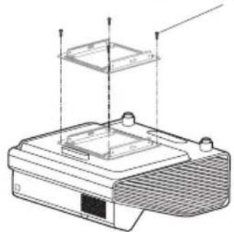
2 Install the projector on the Projector Wall Mount.
Slide the mounting plate with projector attached onto the setting plate. Secure the mounting plate with M5 × 10 mm fasteners (4), as shown below.
natural_image
Technical line drawing of a device assembly showing a mounted component and a base with mounting holes (no text or symbols)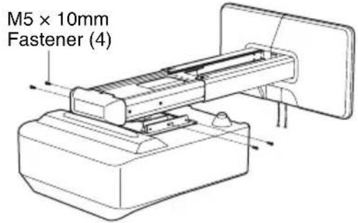
3 Connect the power cable and other cables to the projector.
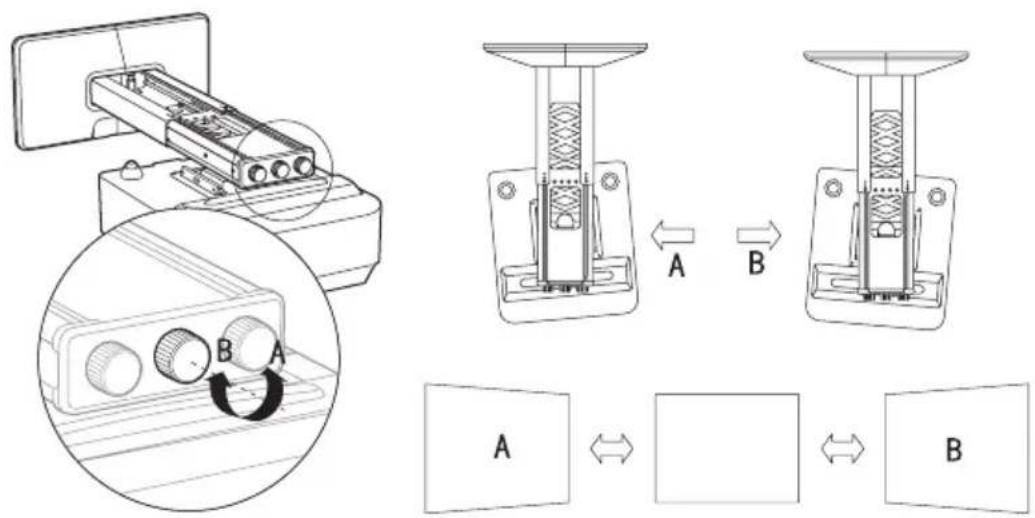
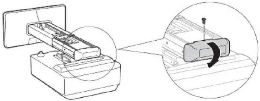
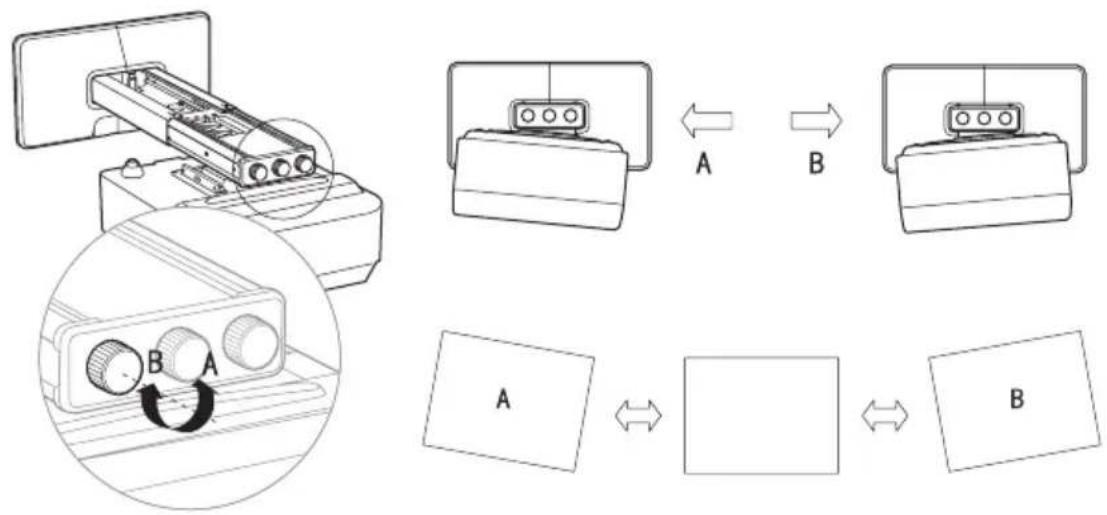
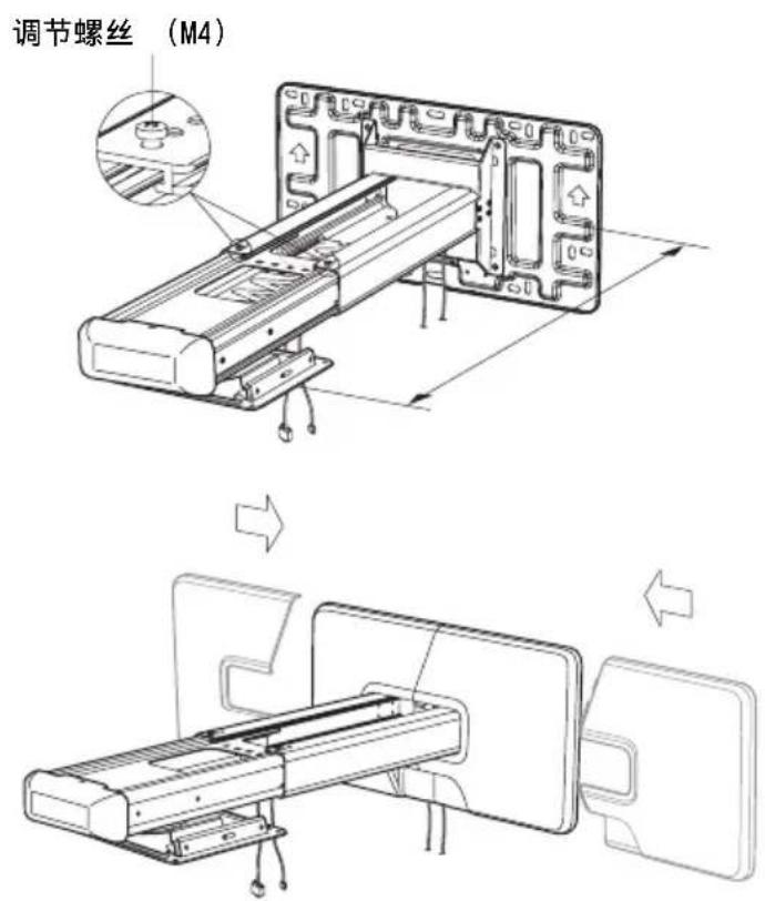
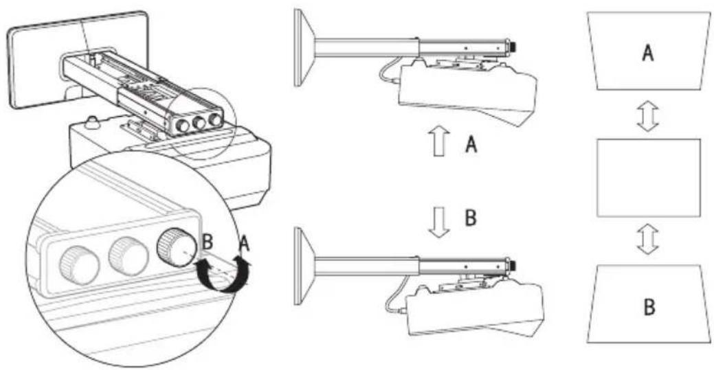
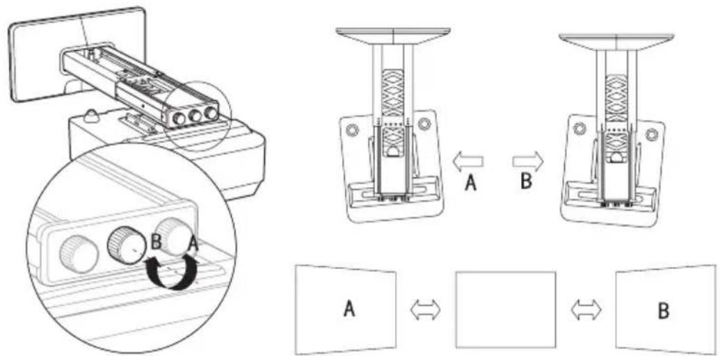
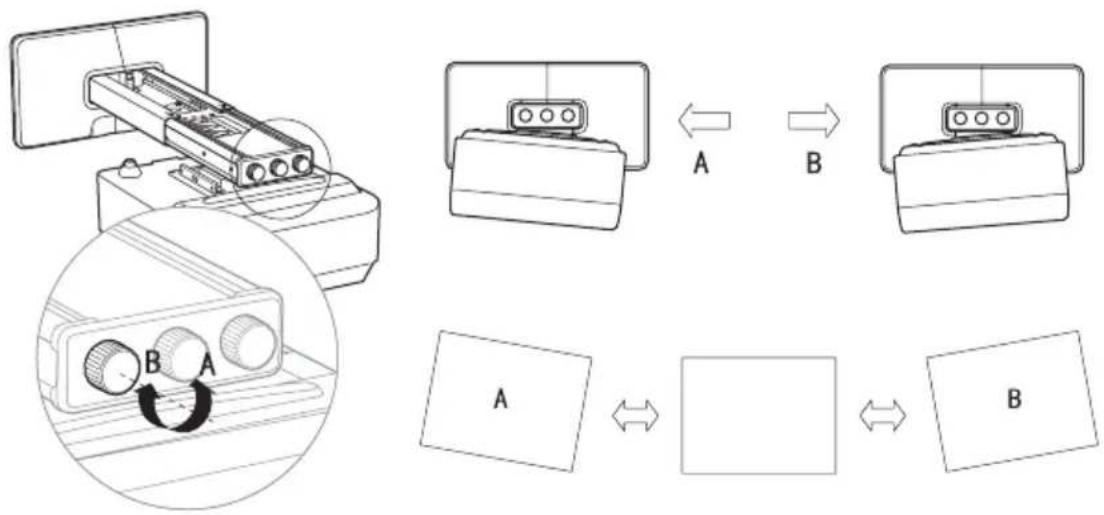
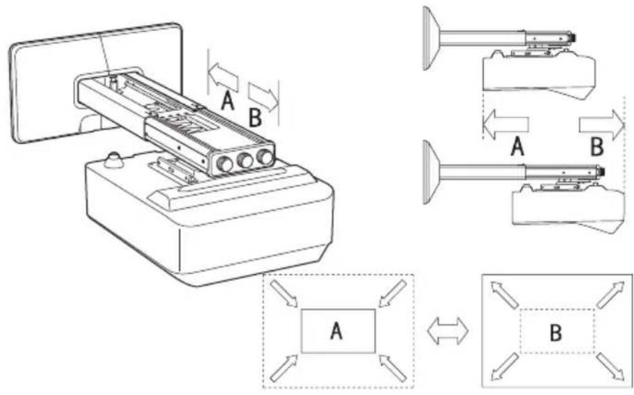
Adjusting the Projection Screen
Remove the dial cover before adjustment. Re-attach the dial cover after adjustment.
natural_image
Diagram showing a printer with internal components being processed, and a close-up of the printer's internal structure with a rotating arrow (no text or symbols present)To adjust the vertical tilt

To adjust the horizontal rotation

To adjust the horizontal roll
flowchart
graph TD
    A["Device 1"] -->|A| B["Component 1"]
    B -->|B| C["Component 2"]
    C --> D["Data Transfer"]
    D --> E["Output Box 1"]
    style A fill:#f9f,stroke:#333
    style B fill:#ccf,stroke:#333
    style C fill:#cfc,stroke:#333
    style D fill:#fcc,stroke:#333
    style E fill:#cff,stroke:#333
To adjust the forward/backward slide
Specification
| Item Description |
| Mass Approx. 4.8 kg (10 lb 9 oz) |
| Adjustable angle Vertical tilt, horizontal rotation, horizontal roll ± 5^ (in 3 directions) |
| Adjustable range Horizontal distance from the center of mounting plate280 mm - 690 mm ( 11^1/_32 inches - 27^5/_32 inches) |
| Maximum load 10 kg (22 lb 1 oz) |
Holder: Sony (China) Limited, Shanghai Branch
Address: 8/F, One Corporate Avenue, 222 Hu Bin Rd., Huangpu District, Shanghai
Dimensions
VPL-SW536C/SW536/SW526C/SW526/SW535C/SW535/SW525C/SW525/SX536/SX535
When the arm is secured with the method A
When the arm is secured with the method B
VPL-SW630C/SW620C/SW630/SW620/SX630
When the arm is secured with the method A
When the arm is secured with the method B
Français
ATTENTION
natural_image
Technical line drawing of a mechanical assembly with mounting flanges and a central rod (no text or symbols)Plaque murale (1)
natural_image
Technical line drawing of a mechanical component with mounting holes and internal cavity (no text or symbols)natural_image
Pure technical drawing of a rectangular plate with a central square cutout and mounting holes (no text or symbols)natural_image
Two 3D mechanical component cutouts (no text or symbols)Boulon M4 × 10 (4)

Boulon M6 × 10 (4)

Clé hexagonale (1)
Vis auto-taraudeuse M6 × 55 (5)
| VPL-SW536C/SW536/SW526C/SW526/SW535C/SW535/SW525C/SW525/SX536/SX535 | VPL-SW630C/SW620C/SW630/SW620/SX630 |
| 190,0 (7 1/2) 189,4 (7 1/2) |
| VPL-SW536C/SW536/SW526C/SW526/SW535C/SW535/SW525C/SW525/SX536/SX535 | VPL-SW630C/SW620C/SW630/SW620/SX630 |
| 65 (2 5/8) 77 (3 1/8) |
VPL-SW536C/SW536/SW526C/SW526/SW535C/SW535/SW525C/SW525
| Taille de l’écran | Distance de projection Y-X | Hauteur B du centre de la plaque du mur au bord de l’écran | |
| Diagonale D | Largeur × Hauteur | ||
| 70 pouces (1,78 m) | 1,51 × 0,94 (59 × 37) | 0,284-0,296 (11 1/4-11 5/8) | 0,328 (13) |
| 80 pouces (2,03 m) | 1,72 × 1,08 (68 × 42) | 0,344-0,358 (13 5/8-14) | 0,349 (13 3/4) |
| 90 pouces (2,29 m) | 1,94 × 1,21 (76 × 48) | 0,403-0,419 (15 7/8-16 1/2) | 0,369 (14 5/8) |
| 100 pouces (2,54 m) | 2,15 × 1,35 (85 × 53) | 0,462-0,480 (18 1/4-18 7/8) | 0,390 (15 3/8) |
| 130 pouces (3,30 m) | 2,80 × 1,75 (110 × 69) | 0,640-0,664 (25 1/4-26 1/8) | 0,452 (17 7/8) |
Unité : m (pouces)
VPL-SX536/SX535
| Taille de l’écran | Distance de projection Y-X | Hauteur B du centre de la plaque du mur au bord de l’écran | |
| Diagonale D | Largeur × Hauteur | ||
| 60 pouces (1,52 m) | 1,22 × 0,91 (48 × 36) | 0,293-0,305 (11 5/8-12) | 0,353 (14) |
| 70 pouces (1,78 m) | 1,42 × 1,07 (56 × 42) | 0,364-0,377 (14 3/8-14 3/4) | 0,382 (15 1/8) |
| 80 pouces (2,03 m) | 1,63 × 1,22 (64 × 48) | 0,434-0,450 (17 1/8-17 5/8) | 0,410 (16 1/4) |
| 90 pouces (2,29 m) | 1,83 × 1,37 (72 × 54) | 0,505-0,523 (19 7/8-20 1/2) | 0,439 (17 3/8) |
| 110 pouces (2,79 m) | 2,24 × 1,68 (88 × 66) | 0,646-0,668 (25 1/2-26 1/4) | 0,495 (19 1/2) |
Unité : m (pouces)
VPL-SW630C/SW620C/SW630/SW620
| Taille de l’écran | Distance de projection Y-X | Hauteur B du centre de la plaque du mur au bord de l’écran | ||
| Diagonale D | Largeur × Hauteur | Distance de projection Y-X (min.) | Distance de projection Y-X (max.) | |
| 65 pouces(1,65 m) | 1,40 × 0,88(55 × 34) | 0,309-0,320(12 1/4 - 12 5/8) | 0,445(17 5/8) | 0,446(17 5/8) |
| 70 pouces(1,78 m) | 1,51 × 0,94(59 × 37) | 0,340-0,352(13 1/2-13 7/8) | 0,466(18 3/8) | 0,467(18 1/2) |
| 80 pouces(2,03 m) | 1,72 × 1,08(68 × 42) | 0,403-0,417(15 7/8-16 1/2) | 0,509(20 1/8) | 0,510(20 1/8) |
| 90 pouces(2,29 m) | 1,94 × 1,21(76 × 48) | 0,466-0,482(18 3/8-19) | 0,551(21 3/4) | 0,552(21 3/4) |
| 100 pouces(2,54 m) | 2,15 × 1,35(85 × 53) | 0,529-0,547(20 7/8-21 5/8) | 0,593(23 3/8) | 0,595(23 1/2) |
| 110 pouces(2,79 m) | 2,37 × 1,48(93 × 58) | 0,592-0,612(23 3/8-24 1/8) | 0,636(25 1/8) | 0,637(25 1/8) |
Unité : m (pouces)
VPL-SX630
| Taille de l’écran | Distance de projection Y-X | Hauteur B du centre de la plaque du mur au bord de l’écran | ||
| Diagonale D | Largeur × Hauteur | Distance de projection Y-X (min.) | Distance de projection Y-X (max.) | |
| 70 pouces(1,78 m) | 1,42 × 1,07(56 × 42) | 0,315-0,327(12 1/2-12 7/8) | 0,362(14 3/8) | 0,362(14 3/8) |
| 80 pouces(2,03 m) | 1,63 × 1,22(64 × 48) | 0,375-0,388(14 7/8-15 3/8) | 0,389(15 3/8) | 0,390(15 3/8) |
| 90 pouces(2,29 m) | 1,83 × 1,37(72 × 54) | 0,434-0,449(17 1/8-17 3/4) | 0,417(16 1/2) | 0,417(16 1/2) |
| 100 pouces(2,54 m) | 2,03 × 1,52(80 × 60) | 0,494-0,510(19 1/2-20 1/8) | 0,444(17 1/2) | 0,445(17 5/8) |
| 110 pouces(2,79 m) | 2,24 × 1,68(88 × 66) | 0,553-0,571(21 7/8-22 1/2) | 0,472(18 5/8) | 0,472(18 5/8) |
| 115 pouces(2,92 m) | 2,34 × 1,75(92 × 69) | 0,583-0,602(23-23 3/4) | 0,485(19 1/8) | 0,486(19 1/4) |
Unité : m (pouces)
natural_image
Technical line drawing of a mechanical assembly with exploded and assembled views (no text or symbols)Câbles d'ordinateur
VPL-SW536C/SW536/SW526C/SW526/SW535C/SW535/SW525C/SW525/SX536/SX535
VPL-SW630C/SW620C/SW630/SW620/SX630
Boulon M4 × 10 mm (4)
natural_image
Technical line drawing of a portable air conditioner unit with mounting base and ventilation slots (no text or symbols)Boulon M4 × 10 mm (4)
natural_image
Technical line drawing of a mechanical assembly with layered components and mounting holes (no text or symbols)natural_image
Technical line drawing of a device with an open base and internal components, no text or symbols present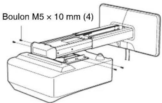
natural_image
Diagram showing a printer or scanner device being processed, with an inset close-up illustrating the process (no text or symbols present)Spécifications
VPL-SW536C/SW536/SW526C/SW526/SW535C/SW535/SW525C/SW525/SX536/SX535
VPL-SW630C/SW620C/SW630/SW620/SX630
natural_image
Technical line drawing of a mechanical assembly with mounting flanges and a central rod (no text or symbols)Placa de pared (1)
natural_image
Pure technical diagram of a mechanical component with no text, numbers, or symbolsPlantilla de placa de pared
natural_image
Pure technical drawing of a rectangular plate with a central square cutout and mounting holes (no text or symbols)Tapa de la placa de pared (1)

natural_image
Technical line drawing of two mechanical component parts (no text or symbols)Fijador M4 × 10 (4)

Fijador M6 × 10 (4)

Llave allen (1)
Tornillo autorroscante M6 × 55 (5)
| VPL-SW536C/SW536/SW526C/SW526/SW535C/SW535/SW525C/SW525/SX536/SX535 | VPL-SW630C/SW620C/SW630/SW620/SX630 |
| 190,0 (7 1/2) 189,4 (7 1/2) |
| VPL-SW536C/SW536/SW526C/SW526/SW535C/SW535/SW525C/SW525/SX536/SX535 | VPL-SW630C/SW620C/SW630/SW620/SX630 |
| 65 (2 5/8) 77 (3 1/8) |
VPL-SW536C/SW536/SW526C/SW526/SW535C/SW535/SW525C/SW525
VPL-SW536C/SW536/SW526C/SW526/SW535C/SW535/SW525C/SW525/SX536/SX535
VPL-SW630C/SW620C/SW630/SW620/SX630
natural_image
Technical line drawing of a device with mounting holes and a base plate (no text or symbols)natural_image
Technical line drawing of a mechanical assembly with layered components and mounting holes (no text or symbols)natural_image
Technical line drawing of a device with an open base and internal components, showing no text or symbols.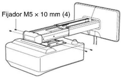
natural_image
Diagram showing a printer or scanner device being processed, with an inset close-up illustrating the process (no text or symbols present)Especificaciones
Dirección: 8/F, One Corporate Avenue, 222 Hu Bin Rd., Huangpu District, Shanghai
Dimensiones
VPL-SW536C/SW536/SW526C/SW526/SW535C/SW535/SW525C/SW525/SX536/SX535
VPL-SW630C/SW620C/SW630/SW620/SX630
natural_image
Technical line drawing of a mechanical assembly with mounting flanges and a central rod (no text or symbols)Inbusschlüssel (1)

natural_image
Technical line drawing of a mechanical component with no visible text or symbolsDurchm. 11 × 50 Ankerbolzen (5)
natural_image
Simple line drawing of a rectangular plate with a central square cutout and corner holes (no text or symbols)natural_image
Technical line drawing of two mechanical components (no text or symbols)| VPL-SW536C/SW536/SW526C/SW526/SW535C/SW535/SW525C/SW525/SX536/SX535 | VPL-SW630C/SW620C/SW630/SW620/SX630 |
| 65 77 |
VPL-SW536C/SW536/SW526C/SW526/SW535C/SW535/SW525C/SW525
VPL-SW630C/SW620C/SW630/SW620
VPL-SW536C/SW536/SW526C/SW526/SW535C/SW535/SW525C/SW525/SX536/SX535
VPL-SW630C/SW620C/SW630/SW620/SX630
natural_image
Technical line drawing of a device assembly showing a mounted component and a base with mounting holes (no text or symbols)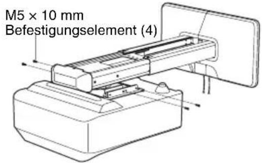
natural_image
Diagram showing a printer or scanner device being processed, with an inset close-up illustrating the process (no text or symbols present)Spezifikation
Inhaber: Sony (China) Limited, Niederlassung Shanghai Adresse: 8/F, One Corporate Avenue, 222 Hu Bin Rd., Huangpu District, Shanghai
Abmessungen
VPL-SW536C/SW536/SW526C/SW526/SW535C/SW535/SW525C/SW525/SX536/SX535
VPL-SW630C/SW620C/SW630/SW620/SX630
natural_image
Technical line drawing of a mechanical assembly with mounting flanges and a central rod (no text or symbols)natural_image
Technical line drawing of a mechanical component with no visible text or symbolsnatural_image
Simple line drawing of a rectangular plate with a central square cutout and corner holes (no text or symbols)natural_image
Two 3D mechanical parts with cutouts, no text or symbols visible| VPL-SW536C/SW536/SW526C/SW526/SW535C/SW535/SW525C/SW525/SX536/SX535 | VPL-SW630C/SW620C/SW630/SW620/SX630 |
| 65 77 |
VPL-SW536C/SW536/SW526C/SW526/SW535C/SW535/SW525C/SW525
VPL-SW630C/SW620C/SW630/SW620
VPL-SW536C/SW536/SW526C/SW526/SW535C/SW535/SW525C/SW525/SX536/SX535
VPL-SW630C/SW620C/SW630/SW620/SX630
natural_image
Technical line drawing of a device assembly showing a mounted component and its base case (no text or symbols)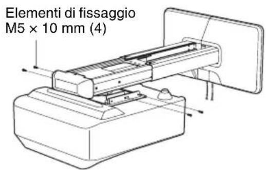
natural_image
Diagram showing a printer or scanner device being processed, with a magnified inset illustrating the process (no text or symbols present)flowchart
graph TD
    A["Component A"] --> B["Component B"]
    B --> C["Assembly Step A"]
    C --> D["Assembly Step B"]
    D --> E["Final Assembly Box"]
VPL-SW536C/SW536/SW526C/SW526/SW535C/SW535/SW525C/SW525/SX536/SX535
VPL-SW630C/SW620C/SW630/SW620/SX630
natural_image
Technical line drawing of a mechanical assembly with mounting flanges and a central shaft (no text or symbols)墙面板 (1)
natural_image
Technical line drawing of a mechanical component with mounting holes and internal cavity (no text or symbols)墙面安装模板
natural_image
Simple line drawing of a rectangular plate with a central square cutout and corner holes (no text or symbols)墙面板盖 (1)
natural_image
Two 3D mechanical component cutouts, one with a V-shaped notch and the other a rectangular plate (no text or symbols)M4 × 10 螺丝 (4)

M6 × 10 螺丝 (4)

L 形内六角扳手 (1)
M6 × 55 自攻螺丝 (5)
直径 11 × 50 锚定螺栓 (5)

检查安装位置
确定固定支撑臂的方法
| VPL-SW536C/SW536/SW526C/SW526/SW535C/SW535/SW525C/SW525/SX536/SX535 | VPL-SW630C/SW620C/SW630/SW620/SX630 |
| 190.0 189.4 |
| VPL-SW536C/SW536/SW526C/SW526/SW535C/SW535/SW525C/SW525/SX536/SX535 | VPL-SW630C/SW620C/SW630/SW620/SX630 |
| 65 77 |
投影距离表
VPL-SW536C/SW536/SW526C/SW526/SW535C/SW535/SW525C/SW525
natural_image
Technical line drawing of a mechanical assembly with an inset showing a component detail (no text or symbols present)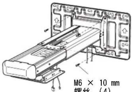
3调节支撑臂的长度并安装墙面板盖。
将投影机安装在投影机吊架上
VPL-SW536C/SW536/SW526C/SW526/SW535C/SW535/SW525C/SW525/SX536/SX535
VPL-SW630C/SW620C/SW630/SW620/SX630
M4 × 10 mm 螺丝 (4)
natural_image
Technical line drawing of a device with mounting holes and a central panel (no text or symbols)M4 × 10 mm 螺丝 (4)
natural_image
Technical line drawing of a mechanical assembly with two components and mounting base (no text or symbols)2 将投影机安装在投影机吊架上。
natural_image
Technical line drawing of a device assembly showing a component being inserted into a housing (no text or symbols present)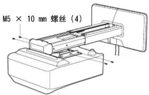
3将电源线和其他电缆连接至投影机。
调节投影画面
natural_image
Diagram showing a printer or scanner device being processed, with an inset close-up of the device's internal structure (no text or symbols present)调节纵向倾斜度
调节水平转角
调节横向摆角
flowchart
graph TD
    A["Device 1"] -->|A| B["Component 1"]
    B -->|B| C["Component 2"]
    C --> D["Data Table"]
    D -->|A| E["Output Box"]
    D -->|B| F["Final Output Box"]
调节前 / 后滑动距离
规格
项目 说明
质量 约 4.8 kg
VPL-SW536C/SW536/SW526C/SW526/SW535C/SW535/SW525C/SW525/SX536/SX535
使用方法 A 固定支撑臂时