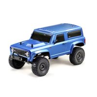
CR3.4eco - Remote control toy Absima - Free user manual and instructions
Find the device manual for free CR3.4eco Absima in PDF.


| Product type | Radio-controlled off-road car |
| Brand | Absima |
| Model | CR3.4eco |
| Radio frequency | 2.4 GHz |
| Number of channels | 4 (CH1 steering, CH2 throttle/brake, CH3 3-position switch, CH4 push button) |
| Transmitter power supply | 4 LR6 (AA) 1.5 V batteries or LiPo 2S 7.4 V battery (optional) |
| Vehicle power supply | LiPo 2S-3S or NiMH 5-9 cell battery |
| Motor type | Brushed 540/550 |
| Speed controller (ESC) | 60 A with brake, compatible with 2-3S LiPo / 5-9 NiMH, BEC output 3A/6V |
| Drivetrain | 4-wheel drive |
| Main functions | Forward, brake, reverse (double-click mode), steering, trim and dual rate adjustments |
| Beginner mode | Speed limitation at 50% |
| Protections | Battery undervoltage, overheating, radio signal loss |
| Routine maintenance | Cleaning after use, checking bearings and differentials, lubrication |
| Safety | Do not use in rain, on public roads, or near unsupervised children |
| Spare parts and repairability | Available at www.absima.com |
| Warranty | Manufacturer's warranty on material and functional defects at the time of purchase |
| Certifications | CE conformity |
Frequently Asked Questions - CR3.4eco Absima
User questions about CR3.4eco Absima
0 question about this device. Answer the ones you know or ask your own.
Ask a new question about this device
Download the instructions for your Remote control toy in PDF format for free! Find your manual CR3.4eco - Absima and take your electronic device back in hand. On this page are published all the documents necessary for the use of your device. CR3.4eco by Absima.
USER MANUAL CR3.4eco Absima
CR3.4 1:10 SCALE 4WD ELECTRIC CRAWLER eco
Notiz

This manual is written in german language only. If you need a manual in your language please visit our website or contact your distributor!
Thank you for purchasing this ABSIMA Product.
Please take some time to read through to get familiar with the shown steps.
We continually improve our products, due to that, actual parts my be different to the illustrations.
Please check our website for the latest versions manuals and tips before you start to built this model.
This manual is written in english language only. If you need a manual in your language please visit our website or contact your distributor!
Not suitable for children under 14 years of age without adult supervision.
This is a high performance vehicle, for safety reason don't run on public streets, in crowded areas, environmentally areas or near children or animals.
This model contains rotationg parts and parts which become hot during operation. Care must be taken to avoid damage or injuries.
This product may require some assembly and routine maintenance.
This product is covered by warranty based on material defectives. Crash damage or maintenance failures are not covered under warranty.
Batteries should be used in good condition only, and need to be fully charged.
Keep chemicals stored out of the range of small children.
Make sure your model and equipment is in perfect condition before you use it, to ensure savety and fun while driving.

natural_image
Abstract green and black geometric logo design (no text or symbols)
ABSIMA
Basic information for a safety operation of a rc model car.
Dear customer,
thank you that you have chosen a high-performance product from Absima.
Our products have been designed for beginners, hobby pilots and competition ambitious drivers. Absima wants you to have fun and success with your new model and we therefore recommend that you read the following points carefully.
Before each driving:
- Please check all screws are properly fitting.
- For screws which abut on metal, you should check whether there is enough security screws paint.
- The servo saver should always be set so that it works smoothly and is not too tight otherwise the servo gets damaged.
- Check on your remote control and the vehicle the batteries whether these are still fully charged.
- Check on your remote control, the TRIM settings that the wheels are straight and that you have enough steering angle.
After each driving:
• If you have driven in dirty terrain, it is advisable to clean the completely car.
- If you are driving through rain or water you have to dry the entire vehicle, otherwise all metal parts will rust. To displace moisture is WD40 just right.
• After several trips we recommend that you check the bearings if they are still functioning properly.
• After several trips we recommend that you check out the differentials in the vehicle.
• General visual check after every ride
Electric cars:
- Before you driving an electric vehicle for the first time, you should retract the electric motor. Proceed as follows:
-
Drive the first 2 batteries only with half throttle.
-
Then you can go on as usual normal.
Adjusting the distance between the motor pinion and main gear (if needed).
Loosen the motor screws from motor mount and push the motor away from the main gear. Take a sheet of paper and hold it between the motor pinion and main gear. Now slide the engine completely to the main gear. Pull out the sheet of paper, now the correct distance between the motor pinion and main gear is made.
Declaration of conformity
The manufacturer hereby declares that the product complies with the essential requirements and other relevant provisions of the EU Directive.
The declaration of conformity can be found at http://absima.com/index.php/downloads/erklaerungen/
or can be consulted under
Absima GmbH - Gibitzenhofstrasse 127a/RG - 90443 Nuremberg, Germany can be requested.

ABSIMA

General Information
ATTENTION: Batteries and rechargeable batteries in your transmitter should always be fully charged! Never use the model when they are completely empty. Why? The transmitter could switch itself off, the signal would be lost to your RC Model and it could have a mind of its own.
- this could be very expensive
Getting Started:
Switch on transmitter, hold vehicle clear of the ground, connect battery pack and switch on receiver. Test the transmitter to check control of the vehicle with wheels off the ground. Start driving slowly and if the vehicle does not go straight, adjust steering trim dial on Transmitter. For the very first run use the throttle gently, to help the driver become accustomed to the vehicles behaviour and controls
Always keep in mind:
This is NOT a toy and must be operated with caution and common sense. Failure to operate this product in a safe and responsible manner could result in damage, injury or damage to other property"
If you switch on the car first, before the transmitter your RC Model could have a mind of its own and could drive off.
Please observe:
Driving in wet conditions:
You shouldn't drive your model through big puddles unnecessarily. The vehicle is not designed to be completely submerged in water. The components of Absima RC Models are water resistant but are not water proof. Components like the motor are only splash proof. Most of all you should take care of the plug connections.
Jumps:
Your RC models is designed to take some rough and tumble and moderate pumps, please bare in mind the bigger the pump the more likely you could damage your RC vehicle.
ABSIMA
SAFETY INSTRUCTIONS ABSIMA RC CAR MODELS
- Please read the manual in full before using your model to ensure safe operation
- Do not use your model at night or if the visibility is bad, this could cause damage to you and your model.
- Do not use the model in direct proximity of people. ABSIMA RC models can reach high speed and could cause serious injuries in case of an accident.
- Do not touch drive components, tires or rims of the model while in use, this could cause serious injuries.
- Do not touch any electronic components of the model after driving, this could cause serious injuries.
- Your model is radio controlled, no radio control system is completely free from interference. You could lose control of your model if this occurs, always use your model in a safe area. If you see signs of interference, stop using your model immediately.
- It's not allowed to use your model in public spaces.
• Only use the recommended rechargeable batterie for your model. - Rechargeable batteries need to be charged with appropriate charger. Please read the instructions for the batteries being used before operating your model, misuse of the batteries could cause serious damage or injury.
• Never leave your rechargeable batteries unattended during charging!
• ALL ABSIMA MODELS GOT AGE 14! - ATTENTION: Before you use your model, the transmitter must be switched on first and turned off last, this way you will not lose control of the model.
Necessary Service-features
This is a preinstalled RTR-model, the following service instructions have to be checked before using for the first time and before every use, for safety. Check the following as a guide and if necessary make the correct adjustments/repairs according to the manual.
- Check all wheels and steering parts are correctly fitted, if necessary adjust accordingly to the supplied manual
- Check the motor pinion and main gear before and after each use to ensure they are securely fixed. If required use thread lock glue on all metal-to-metal screws.
- Clean the model after each use as good as possible, check for any debris or small stones which could get jammed between moving parts.
• If the car has been used in damp weather conditions, ensure the model is fully dried
Warranty Terms

By purchasing and using your Absima product, you agree to the warranty terms of Absima GmbH.
The warranty applies only to material and/or functional defects already present at the time of purchase of the product.
Excluded from the guarantee:
• Damage caused by incorrect use
• Damage due to neglect of duty of care
• Damage due to improper handling and maintenance errors
- Fluid damages
Please report warranty claims to your dealer.
If it is necessary to return your product, please enclose your proof of purchase and a detailed description of the fault with the shipment. We also need your complete contact details (legible).
The direct sending to the service department of Absima GmbH requires the previous arrangement. This can be done by telephone under +49 911 65084130 or by e-mail to service@absima.com
The shipping costs are borne by the sender. Parcels that are not free of charge or are subject to charges will not be accepted.
Each incoming warranty case is first checked by our service department for admissibility. Complaints that are not covered by the warranty may incur costs for the inspection. Repairs or services that are not covered by the warranty will be charged in advance.
Disclaimer
Since Absima GmbH cannot at any time monitor the observance of the operating instructions as well as the operation and conditions of use of the product, Absima GmbH does not assume any liability for damages, costs, losses resulting from incorrect handling and/or incorrect operation or in any way related thereto. To the extent permitted by law, the obligation to pay damages, for whatever legal reason, will be limited to the invoice value of the Absima product involved in the event. This does not apply as far as we have to assume unlimited liability due to mandatory legal regulations or gross negligence.
Declaration of conformity
The manufacturer hereby declares that the product complies with the essential requirements and other relevant provisions of the EU Directive.
The declaration of conformity can be found at
http://absima.com/index.php/downloads/erklaerungen/
or can be consulted under
Absima GmbH - Gibitzenhofstrasse 127a/RG - 90443 Nuremberg, Germany can be requested.
Disposal


Waste electronic equipment is a raw material and should not be disposed of with household waste. If the product is at the end of its service life, dispose of it at your local collection points in accordance with the applicable legal regulations. Disposal with household waste or at the expense of the environment is prohibited.
Important! Remove the batteries or rechargeable batteries before disposal. A separate take-back system applies to batteries and rechargeable batteries.
By properly disposing of your old appliances, you make an important contribution to environmental protection.
Absima GmbH
Gibitzenhofstrasse 127 a / RG
90443 Nürberg, Germany
Phone: +49 911 65084130 / Fax: +49 911 65084140
www.absima.com
Technical changes, design and equipment subject to change without notice.
INFORMATIONS GENERALES

Remove Body-Clip from body post
natural_image
Line drawing of a multi-wheeled SUV with visible tracks and suspension (no text or symbols)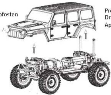
Press down slightly to close the battery mount
natural_image
Technical line drawing of a mechanical assembly with directional arrows indicating motion (no text or symbols)Easily pull up the battery mount
Open the bodyshell and the battery mount
Insert the fully charged battery and close the battery mount
Radio System Instructions
natural_image
Technical line drawing of a battery pack with four cells and two terminals (no text or symbols)Functions of radio switches
Make sure that the ESC is off and connect the battery cable with the ESC
After switch on the radio, you could also activate the ESC/Car
Slide in the direction of the arrow to open the radio battery cover
Install 4* AA batteries with sufficient power – pay attention for polarity +/- - and close the cover
CH 1 - Steering wheel
- CH 1 - Lenkrad
Ch 1 – Le volant
CH 2 - Throttle trigger
- CH 2 - Gashebel
CH 2 - Accélérateur
Push button switch (Ch4)
- Drucktaste (CH4)
bouton-poussoir (CH4)
Three-position toggle switch (Ch3)
- 3-Positionen Kippschalter (CH3)
Pull Throttle trigger for vehicle forward.
Push trigger one time for brake, pause will auto return trigger to center. Push second time for Reverse.
Turn the steering wheel to turn left/right
natural_image
Technical line drawing of a mechanical fan or wheel assembly with directional arrows indicating motion (no text or symbols)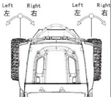
1. Sicherheit
natural_image
Diagram of a device rear panel with internal grid layout and polarity indicators (no text or symbols)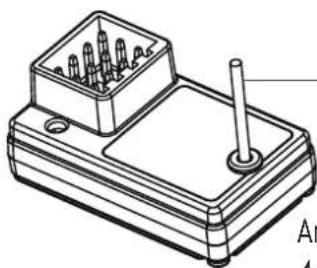
natural_image
Technical line drawing of a mechanical component with a base and top plate (no text or symbols)Pay close attention to the following symbols and their meanings. Failure to follow these warnings could cause damage, injury or death.
 | Danger | • Not following these instructions may lead to serious injuries or death. |
 | Warning | • Not following these instructions may lead to major injuries. |
 | Attention | • Not following these instructions may lead to minor injuries. |
1.2 Safety Guide

Prohibited

Mandatory

- Do not use the product at night or in bad weather like rain or thunderstorm. It can cause erratic operation or loss of control.
- Do not use the product when visibility is limited.
- Do not use the product on rain or snow days. Any exposure to moisture (water or snow) may cause erratic operation or loss of control.
- Interference may cause loss of control. To ensure the safety of you and others, do not operate in the following places:
• Near any site where other radio control activity may occur
• Near power lines or communication broadcasting antennas
• Near people or roads
• On any body of water when passenger boats are present
- Do not use this product when you are tired, uncomfortable, or under the influence of alcohol or drugs. Doing so may cause serious injury to yourself or others.
- The 2.4GHz radio band is limited to line of sight. Always keep your model in sight as a large object can block the RF signal and lead to loss of control.
- Do not touch any part of the model that may generate heat during operation, or immediately after use. The engine, motor or speed control, may be very hot and can cause serious burns.

- Misuse of this product may lead to serious injury or death. To ensure the safety of you and your equipment, read this manual and follow the instructions.
- Make sure the product is properly installed in your model. Failure to do so may result in serious injury.
• Make sure to disconnect the reveiver battery before turning off the transmitter. Failure to do so may lead to unintended operation and cause an accident. - Ensure that all motors operate in the correct direction. If not, adjust the direction first.
• Make sure the model stays within the systems maximum range to prevent loss of control.
2. Introduction
The CR4S is a simple 4 channel transmitter using the latest 2.4GHz ATN frequency hopping technology from Absima. The transmitter is lightweight and compact in design, comfortable and ergonomic. It has a beginner mode and is easy for beginner players to use.
2.1 Transmitter overview
![[1] [2] [3] [4] [5] [6]](/content/2026/04/723656/images/6ac0dc5a515235351be81b8d875345250ad765bc08abf50ff15772cee7097a7c.jpg)
![[7] [8] [9] [10] [11] [12] [13] [14] [15] [16]](/content/2026/04/723656/images/d88906544f53c31a176928da1c125acb07fd04c02994b7171189dd3e44ed0949.jpg)
| [1] | Traversing handwheel, 35 degrees on each side (Ch1) | [9] | ST. D/R |
| [2] | Throttle button, 25 degrees in front and 12.5 degrees at rear (CH2) | [10] | TH. D/R |
| [3] | Push button switch (Ch4) [Push button function is flip type] | [11] | TH. REV |
| [4] | Three-position toggle switch (Ch3) | [12] | G. LED |
| [5] | Handle BIND Button | [13] | |
| [6] | Battery compartment, 4 x 1.5V LR6 (AA) | [14] | ST. TRIM |
| [7] | ST. REV TH. TRIM | [15] | |
| [8] | R. LED Power Switch | [16] |
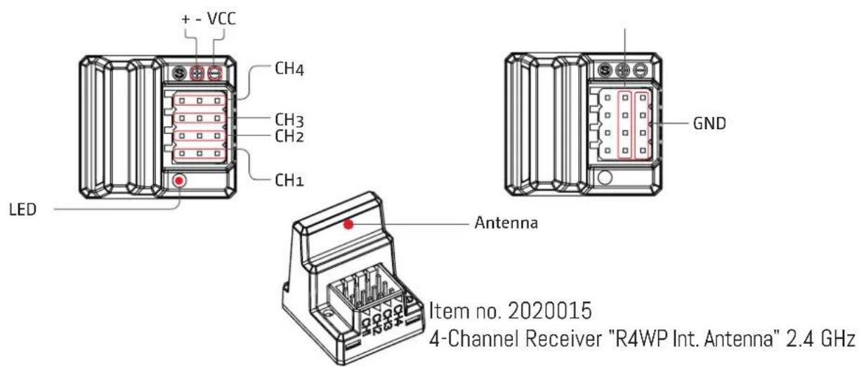
2.2 Receiver overview

natural_image
Diagram of a device rear panel with internal grid and terminal connections (no text or symbols)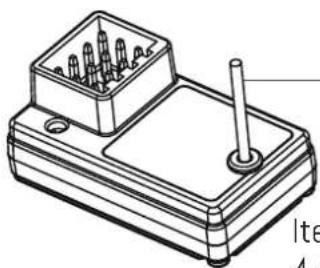
natural_image
Technical line drawing of a mechanical component with pins and a shaft (no text or symbols)Antenna
Item no. 2020016
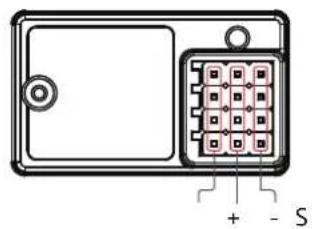
4-Channel Receiver "R4WP-Micro" 2.4 GHz

Note
- To ensure the best signal quality make sure that the antenna is mounted perpendicular to the model body in an upright position.
Accessories sold separately
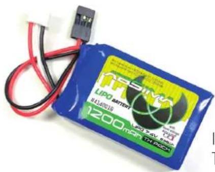
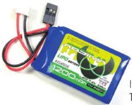
Item no. 4140016
TX LiPo 2S 7.4V 1200mAh SC with LiPo Protect (JR/FUT)
3. Getting Started
Before operation, install the battery and connect the system as instructed below.
3.1 Transmitter Battery Installation
| Danger· | Only use specified battery. |
| Danger· | Do not open, disassemble, or attempt to repair the battery. |
| Danger | · Do not crush/puncture the battery, or short the external contacts. |
| Danger· | Do not expose to excessive heat or liquids. |
| Danger | · Do not drop the battery or expose to strong shocks or vibrations. |
| Danger· | Always store the battery in a cool, dry place. |
| Danger· | Do not use the battery if damaged. |
| Danger · | Only use specified battery. |
| Danger · | Do not open, disassemble, or attempt to repair the battery. |
| Danger | · Do not crush/puncture the battery, or short the external contacts. |
| Danger · | Do not expose to excessive heat or liquids. |
| Danger | · Do not drop the battery or expose to strong shocks or vibrations. |
| Danger · | Always store the battery in a cool, dry place. |
| Danger · | Do not use the battery if damaged. |
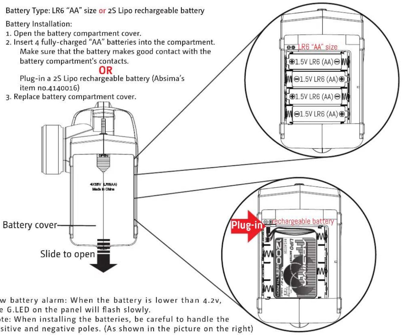

4.Instructions
After setting up, follow the instructions below to operate the system.
4.1 Power On
Follow the steps below to turn on the transmitter:
- Check to make sure that that battery is fully charged and installed correctly.
- Toggle the switch to the [ON] position. When active the R.LED will be lit.
- Connect the receiver to power.
- For safety always power on the transmitter before the receiver.

Note
• Operate with caution in order to avoid damage or injury.

Note
• Make sure that the throttle is at its lowest position and the switches are set to their up position.
4.2 LED
- R.LED: Red power indicator;
- G.LED: Green status indicator;
- Low battery alarm: When the battery is lower than 4.2v, the G.LED on the panel will flash slowly.
4.3 Binding
The transmitter and receiver have already been bound at the factory.
However if the receiver needs to be replaced or additional receivers bound follow these steps:
- Turn on the transmitter while holding the bind button to enter bind mode. G.LED will start flashing quickly.
- Once in bind mode release the bind button.
- The receiver will enter bind mode atomically when powered on.
- Once e binding is successful the receiver's LED will flash slowly and the transmitter's LED will remain solid after being rebooted.
Note: When binding, put the transmitter into bind mode first, then the receiver.
- applicable to the CR4S transmitter and the R4WP receiver. Different receivers have different bind procedures. For more information visit the ABSIMA website for manuals and other related information.
Product information is updated regularly, please visit our website for more information.
4.4 Stick Calibration
This function is used to set the neutral position for throttle and wheel.
Every transmitter is calibrated before leaving the factory, however if recalibration is required, please follow these steps:
- Turn and hold the wheel as far clockwise as it will turn, hold the throttle all the way forward, then turn on the transmitter in calibration mode.
• The R.LED and G.LED will flash twice. - Calibrate wheel: Turn the wheel completely clockwise, then completely counterclockwise.
- When calibration is completed the R.LED will be off.
- Trigger calibration: Pull the trigger back then forward as far as it will go.
- When calibration is completed the G.LED will be off.
- Once calibration is complete press the bind key to save and exit.
4.5 Power Off
Follow the steps below to turn off the system:
- Disconnect the receiver power.
- Toggle the transmitter's power switch to the off position.

Danger
- Make sure to disconnect the receiver power before turning off the transmitter. Failure to do so may lead to damage or serious injury.
5. System Functions
This section focuses on the functions and how to use them.
5.1 Channel Description
The transmitter outputs a total of 4 channels, which are allocated as follows:
- CH1: Steering Wheel
- CH2 : Throttle Trigger
- CH3 : Three-position Switch
- CH4 : Reset Button
Note: By default the output of CH4 is 1000us, after which pressing the button will toggle between 1000 and 2000us.
5.2 Channel Reverse
This function is used to adjust the action direction of the servo or motor.
The ST.REV / TH.REV knobs are the reverse buttons for CH1 and CH2. If the knob is up it indicates reverse, and the down indicates normal.
5.3 Trims
The ST.TRIM is the trims for CH1 (steering), and can be multiplexed as Trims of CH3;
The TH.TRIM is the trims for CH2 (throttle). and can be multiplexed as Trims of CH4;
For multiplexing switching mode, see [5.5 Mode Switching].
Adjustment range: -120us- + 120us;
ST.TRIM/TH.TRIM: counterclockwise adjustment to increase the trim value. The maximum value is 120 us.
ST.TRIM- / TH.TRIM-: clockwise adjustment to decrease the trim value. The minimum value is -120 us.
5.4 D/R
The ST.D/R is the trims for CH1 (steering), and can be multiplexed as Trims of CH3;
The ST.D/R is the trims for CH2 (throttle). and can be multiplexed as Trims of CH4;
For multiplexing switching mode, see [5.5 Mode Switching].
Adjustment range: 0-120%;
ST.D/R: counterclockwise adjustment to increase the servo amount. The maximum value is 120%.
ST.D/R: clockwise adjustment to decrease the servo amount. The minimum value is 0%.
TH.D/R: counterclockwise adjustment to increase the servo amount. The maximum value is 100%.
TH.D/R: clockwise adjustment to decrease the servo amount. The minimum value is 10%.
5.5 Mode switching
This function is for reusing the ST.TRIM and ST.D / R buttons for different channels (see [5.3 Trims], [5.4 D/R]).
Function setting:
Under normal power-on condition, press the BIND button twice (within 1S) to switch between mode 1 and mode 2. By default, mode 1 is used.
Mode 1: R.LED is always on. G.LED is off. ST.TRIM is for CH1 trim. ST.D/R is for CH1 servo adjustment. TH.TRIM is for CH2 throttle trim. TH.D/R is for CH2 throttle servo adjustment.
Mode 2: R.LED and G.LED are flashing alternately. ST.TRIM is for CH3 trim. ST.D/R is for CH3 servo adjustment. TH.TRIM is for CH4 trim. TH.D/R is for CH4 servo adjustment.
5.6 Failsafe
This function dictates what the receiver will do in the event that it loses signal from the transmitter, this includes servo position etc.
Setup:
When the transmitter is switched on in normal communication state, keep the channel to be set at the position of the failsafe setup, and press and hold the BIND button for 3S. The G.LED flashes for 2S, indicating that the setting is successful. That is, when the receiver cannot receive the signal, it will output the set failsafe value.
Note: The fail-sa fe function has no default set at the factory and as such must be set manually. If no failsafe setting has been set, then the receiver will not output anything when signal is lost.
5.7 Beginner Mode
Beginner mode is designed for people new to the hobby.
In this mode the throttle will be limited to 50 percent, The channel range defaults to 1250\~1500\~1750us.
Setup:
To switch between beginner and normal modes, first press and hold the channel 4 button and Turn the handwheel to the bottom counterclockwise, then turn on the transmitter.
Note: By default, the system is set to normal mode. The GLED will flash slowly for 3 seconds during power on if the system is set to beginner mode.
8. Certification
8.1 Warranty Terms
By purchasing and using your Absima product, you agree to the warranty terms of Absima GmbH.
The warranty applies only to material and/or functional defects already present at the time of purchase of the product.
Excluded from the guarantee:
• Damage caused by incorrect use
• Damage due to neglect of duty of care
• Damage due to improper handling and maintenance errors
- Fluid damages
Please report warranty claims to your dealer.
If it is necessary to return your product, please enclose your proof of purchase and a detailed description of the fault with the shipment. We also need your complete contact details (legible).
The direct sending to the service department of Absima GmbH requires the previous arrangement. This can be done by telephone under +49 911 65084130 or by e-mail to service@absima.com
The shipping costs are borne by the sender. Parcels that are not free of charge or are subject to charges will not be accepted.
Each incoming warranty case is first checked by our service department for admissibility. Complaints that are not covered by the warranty may incur costs for the inspection. Repairs or services that are not covered by the warranty will be charged in advance.
8.2 Disclaimer
Since Absima GmbH cannot at any time monitor the observance of the operating instructions as well as the operation and conditions of use of the product, Absima GmbH does not assume any liability for damages, costs, losses resulting from incorrect handling and/or incorrect operation or in any way related thereto. To the extent permitted by law, the obligation to pay damages, for whatever legal reason, will be limited to the invoice value of the Absima product involved in the event. This does not apply as far as we have to assume unlimited liability due to mandatory legal regulations or gross negligence.
8.3 Declaration of conformity
The manufacturer hereby declares that the product complies with the essential requirements and other relevant provisions of the EU Directive.
The declaration of conformity can be found at
http://absima.com/index.php/downloads/erklaerungen/
or can be consulted under
Absima GmbH - Gibitzenhofstrasse 127a/RG - 90443 Nuremberg, Germany can be requested.

8.4 Disposal
Waste electronic equipment is a raw material and should not be disposed of with household waste. If the product is at the end of its service life, dispose of it at your local collection points in accordance with the applicable legal regulations. Disposal with household waste or at the expense of the environment is prohibited.
Important! Remove the batteries or rechargeable batteries before disposal. A separate take-back system applies to batteries and rechargeable batteries.
By properly disposing of your old appliances, you make an important contribution to environmental protection.
Absima GmbH
Gibitzenhofstrasse 127 a / RG
90443 Nürberg, Germany
Phone: +49 911 65084130 / Fax: +49 911 65084140
www.absima.com
Technical changes, design and equipment subject to change without notice.
1. Sécurité
natural_image
Diagram of a device rear panel with internal grid layout and polarity indicators (no text or symbols)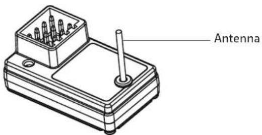

Note
Item no. 2020015
4-Channel Receiver "R4WP Int. Antenna" 2.4 GHz
Item no. 4140016
• Water-proof and dust-proof, suitable for all-weather condition races.
- Small size with built-in capacitor module.
- Three running modes: Forward /Brake, Forward/Brake/Reverse and Forward /Reverse, fits for various vehicles.
• Great current endurance capability.
• Great built-in BEC output capacity.
• Automatic throttle range calibration, easy to use.
- Easy to set the ESC parameters with jumpers.
- Multiple protections: Low voltage cut-off protection for battery / Over-heat protection / Throttle signal loss protection.
ESC Specification:
Fwd. Cont. /Peak Current: 60A/360A
Voltage Range:
2-3S LiPo or 5-9 NiMH
Motor Limit 2S or 6 NIMH:
540/550 Motor ≥12T or RPM<30000 @7.2V
Motor Limit 3S or 9 NiMH:
540 or 550 Size Motor: ≥18T or RPM< 20000 @7.2V
Resistance:
Forward 0.001Ω, Reverse 0.002Ω
BEC Output: 3A / 6V (Switch Mode)
Dimension/Weight: 36.5x32x18 mm / 39g
Cooling Fan: Without cooling fan
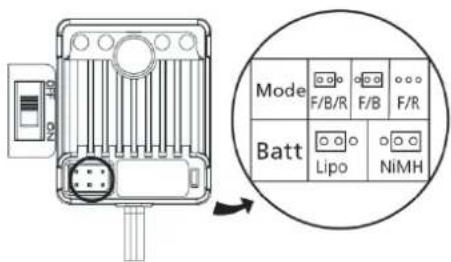
Set the ESC parameters:
How to set:
1060-BRUSHED ESC uses the jumper cap to set running mode & battery type.
Way to set: We suggest users use the tweezers to set parameters by plugging / unplugging the jumper cap (as shown in the picture beside); For example, if want set the battery type to the "LiPo" mode, you only need to plug the jumper cap into left two pins of the battery pin header.
Programmable items:
- Running Mode: 3 Options (Fwd / Br / Rev, Fwd / Br, Fwd / Rev). "Fwd / Br / Rev" is the default option (Fwd=Forward, Br=Brake, Rev=Reverse)
"Fwd / Br / Rev" mode indicates the vehicle can go forward, backward and brake. This mode uses "Double-click" method to make the vehicle reverse. When moving the throttle stick from the neutral zone to backward zone for the 1st time, the ESC begins to brake the motor and the motor slows down but still running, so the backward action is NOT performed immediately. When the throttle stick is moved to the backward zone again, if the motor speed slows down to zero (i.e. stopped), the backward action will happen. This "Double-click" method prevents mistakenly reversing action when the brake function is frequently used in steering. Therefore, this mode is often used in daily practice. For the "Fwd / Br" mode, the vehicle can go forward and brake, but no reversing, so this mode is often used in competition. And the "Fwd / Rev" mode uses "Single-click" method to make the vehicle reverse, when moving the throttle stick from neutral zone to backward zone, the vehicle
reverses immediately, so this mode is usually used for rock crawling.
- Battery Type: Lipo or NiMH, the "Lipo" is the default option.
Protection Features:
- Low Voltage Cutoff Protection: If the voltage of battery pack is lower than the threshold for 2 seconds, the ESC will enter the protection mode, so the motor speed will be lowered (when voltage is lower than the 1st trigger point) till stopped (when voltage is lower than the 2nd trigger point). When the car stops, the red LED blinks to indicate the low voltage cut-off protection has been activated.
2S LiPo: When voltage is below 6.5V, the output power will be halved. When the voltage is lower than 6.0V, the output will be cut off and won't be resumed again.
3S LiPo: When voltage is below 9.75V, the output power will be halved. When the voltage is lower than 9.0V, the output will be cut off and won't be resumed again.
-
Over-heat Protection: When the internal temperature of the ESC is higher than 100^ C, this protection will be activated and the output power will be reduced till cut off. The RED LED blinks when the vehicle stops, and the ESC will not resume output power until its temperature is below 80^ C.
-
Throttle signal loss protection: The ESC will cut off the output power if the throttle signal has been lost for 0.1 second. The "Fail Save" function of the radio system is strongly recommended to be activated.
Trouble Shooting:
| Troubles | Possible Causes | Solutions |
| After power on, no LED lights up, no self-test and no beep sound. | No power is drawn to the ESC; The switch of the ESC is broken. | Check the connections between battery and ESC. Re-solder the connectors if needed; Change the ESC switch. |
| After turn on, the RED LED blinks but the motor doesn't work. | Throttle wire is wrongly plugged or into the incorrect channel; The ESC can't successfully complete the throttle range self-calibration. | Plug the throttle signal wire correctly into the throttle channel (usually Ch2) of the receiver; Set the “TRIM” of throttle channel to 0 or turn the knob to its neutral position. |
| The car runs backwards when accelerating forward on the transmitter. | Direction setting of the throttle channel is incorrect in the transmitter or the motor wires are wrongly connected. | Reverse the direction of the throttle channel, from the original “NOR” to “REV” or “REV” to “NOR”; Swap the wires between the ESC and motor. |
| The vehicle can't reach to the full speed even at the full throttle, and the RED LED doesn't keep lighting. | There are some incorrect settings in the transmitter. | Set D/R, EPA, ATL to 100% or turn the knobs to maximum value. Set TRIM to 0 or turn the knob to its neutral position. |
| Vehicle can't reverse. | The corresponding jumper is plugged into the wrong position; Neutral point of throttle is drifted or deviated. | Insert the jumper into the right location; Set the “TRIM” of the throttle channel to 0 or turn the knob to its neutral point. |
| Motor suddenly stops running. | The throttle signal is lost; The low voltage cutoff protection or thermal protection (i.e. over heat protection) of the ESC is activated. | Check connection between ESC and receiver). Check battery voltage of the transmitter if it is too low; The red LED on the ESC blinks, denoting the ESC is under low voltage cut-off protection or over-heat protection. Let the ESC cool down. If the battery voltage is low, please change the battery. |
| Vehicle neither go forward no reverse, but the LED indicators work normally. | The connection between ESC and motor is interrupted; The motor is damaged. | Check the connectors between the motor and ESC to ensure all connections are firm and reliable; Replace a new motor. |
| The motor accelerates rapidly at the startup moment, but has lockout or cogging problem. | The discharge capacity of the battery is not strong enough; Motor rotates too fast; gear ratio is too aggressive; driveline not ok | Change battery with better discharge capability; Use a motor with lower RPM, or smaller pinion to soften the gear ratio; Check the driveline of the vehicle. |
Differential Gear Assembly

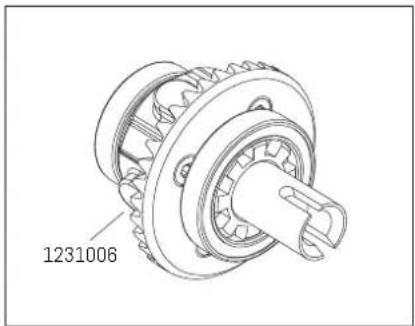
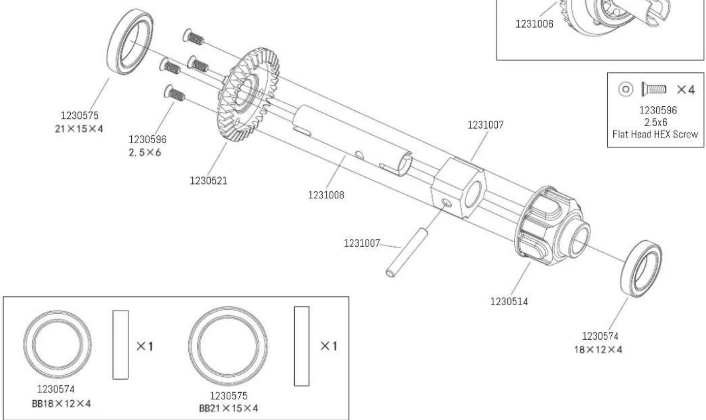
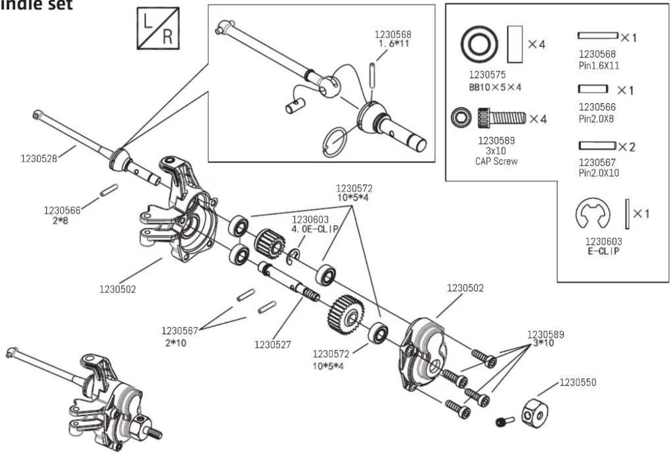
Spindle set
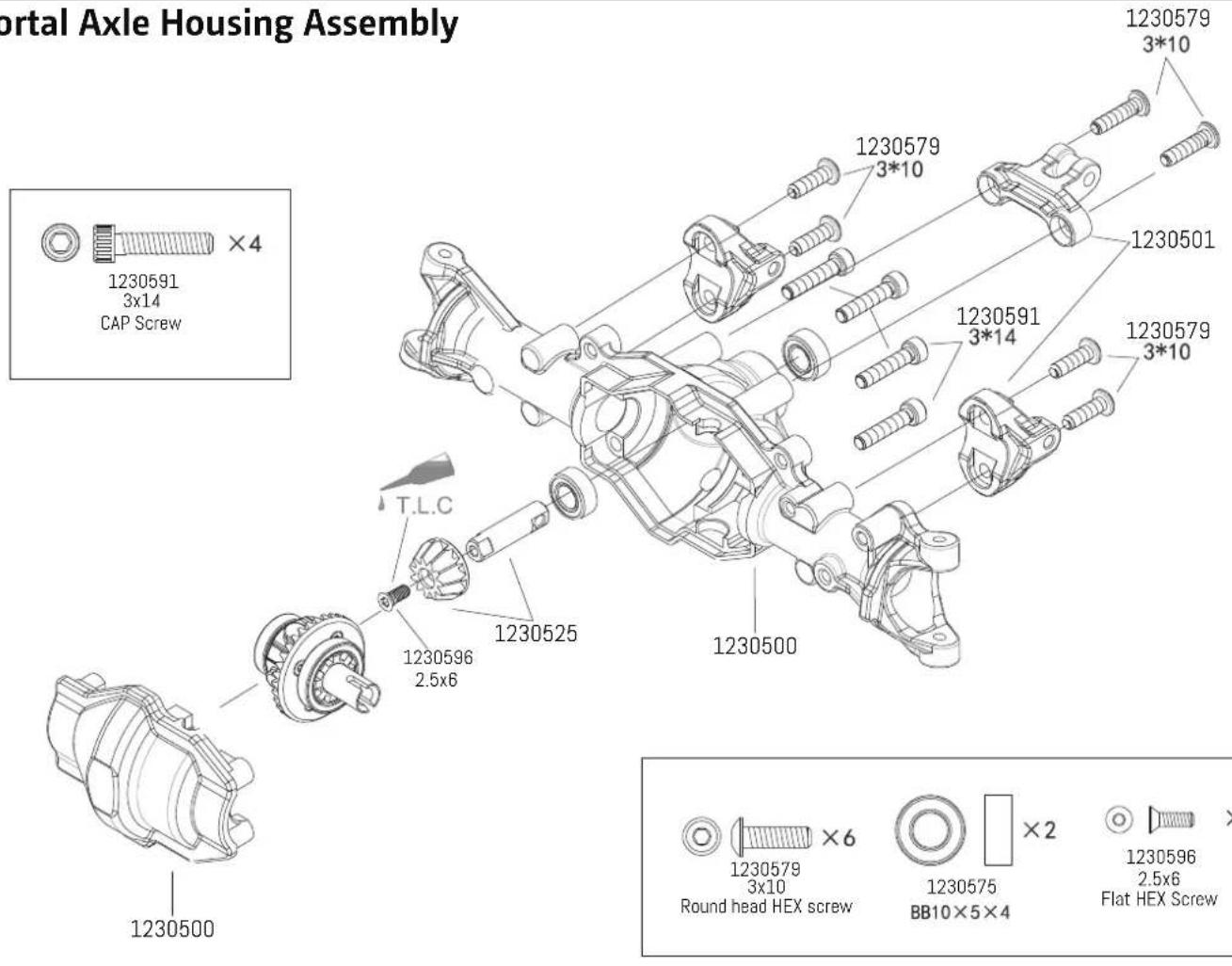
Portal Axle Housing Assembly
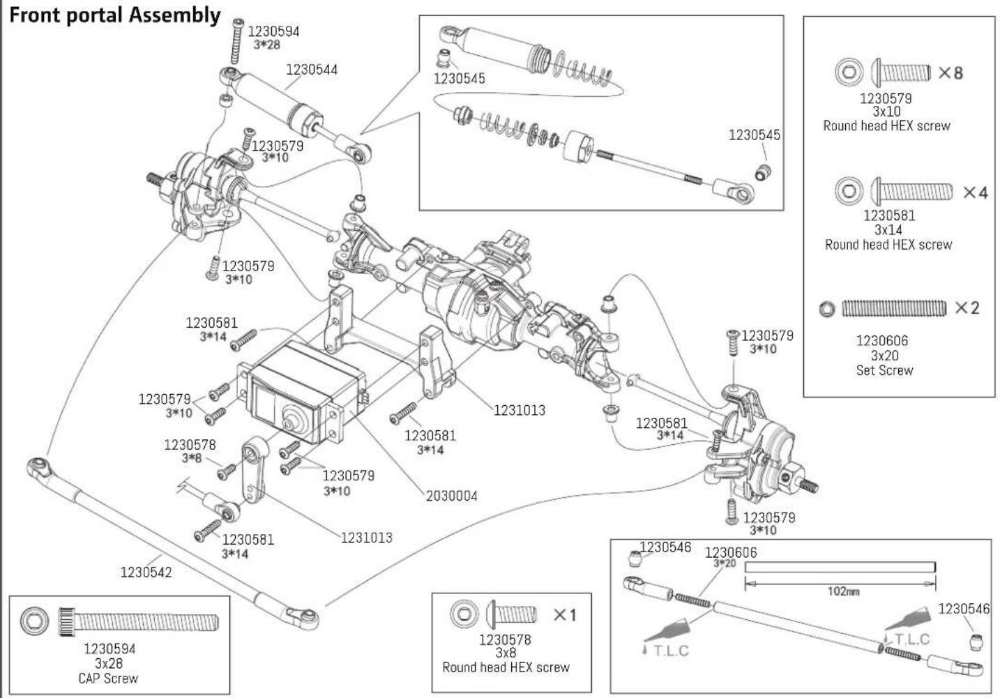
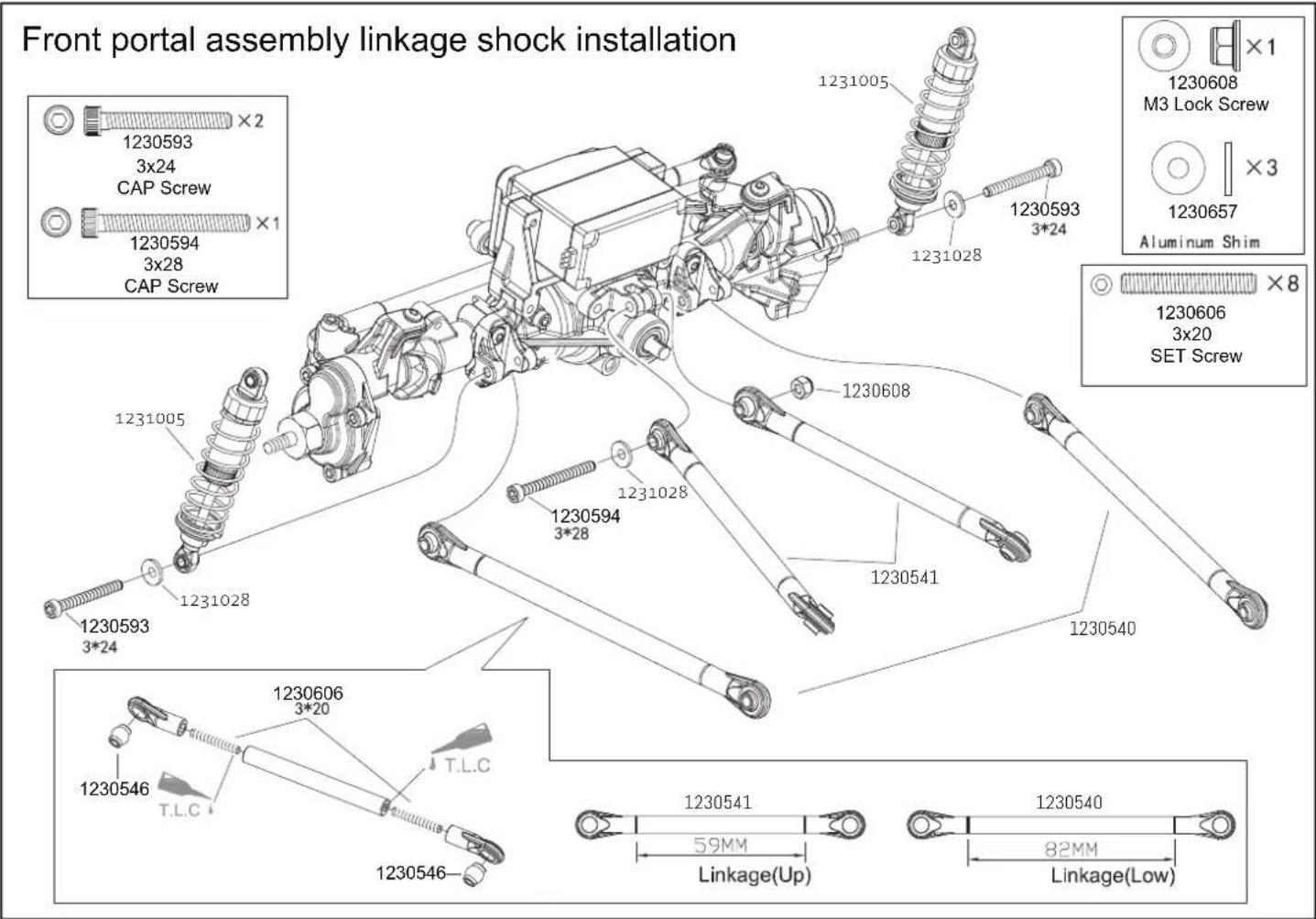
Front portal Assembly
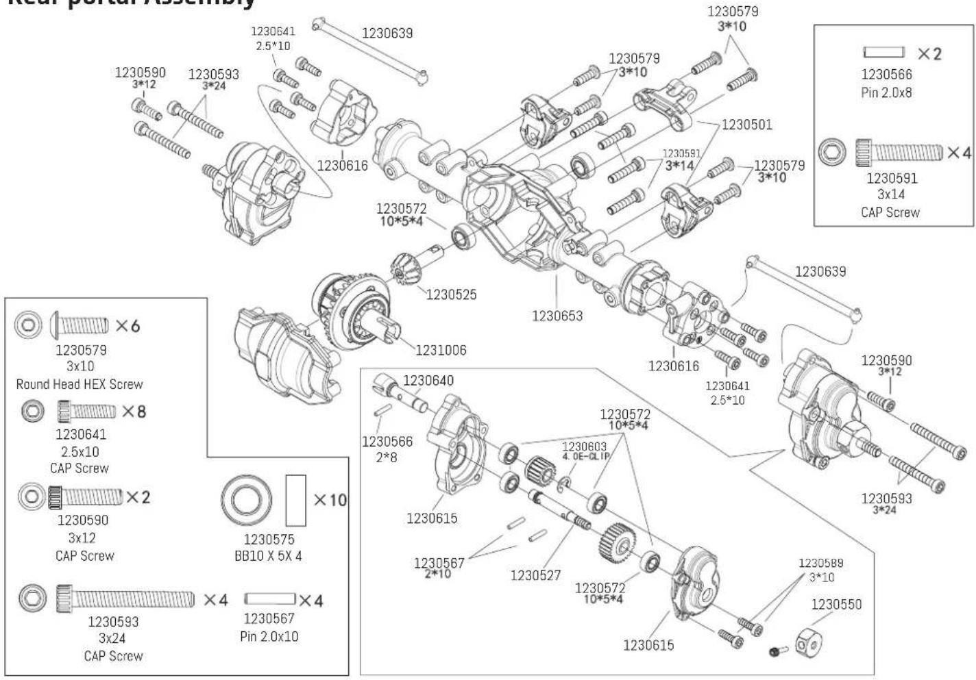
Rear portal Assembly
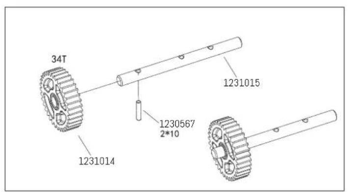
Gearbox Assembly
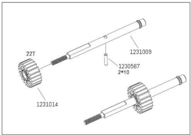
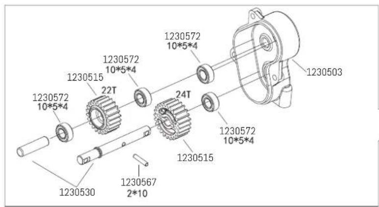
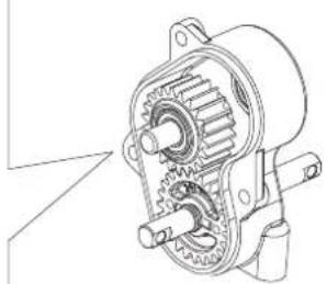
natural_image
Technical line drawing of a mechanical gear assembly (no text or symbols)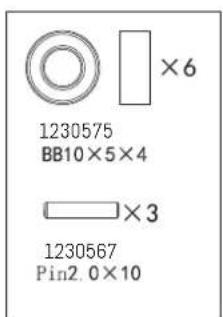
Gearbox Assembly

Battery box Assembly
Receiver box Assembly
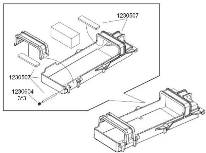
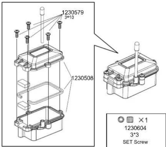


1230604
3*3
SET Screw


1230579
3x10
Round Head HEX Screw
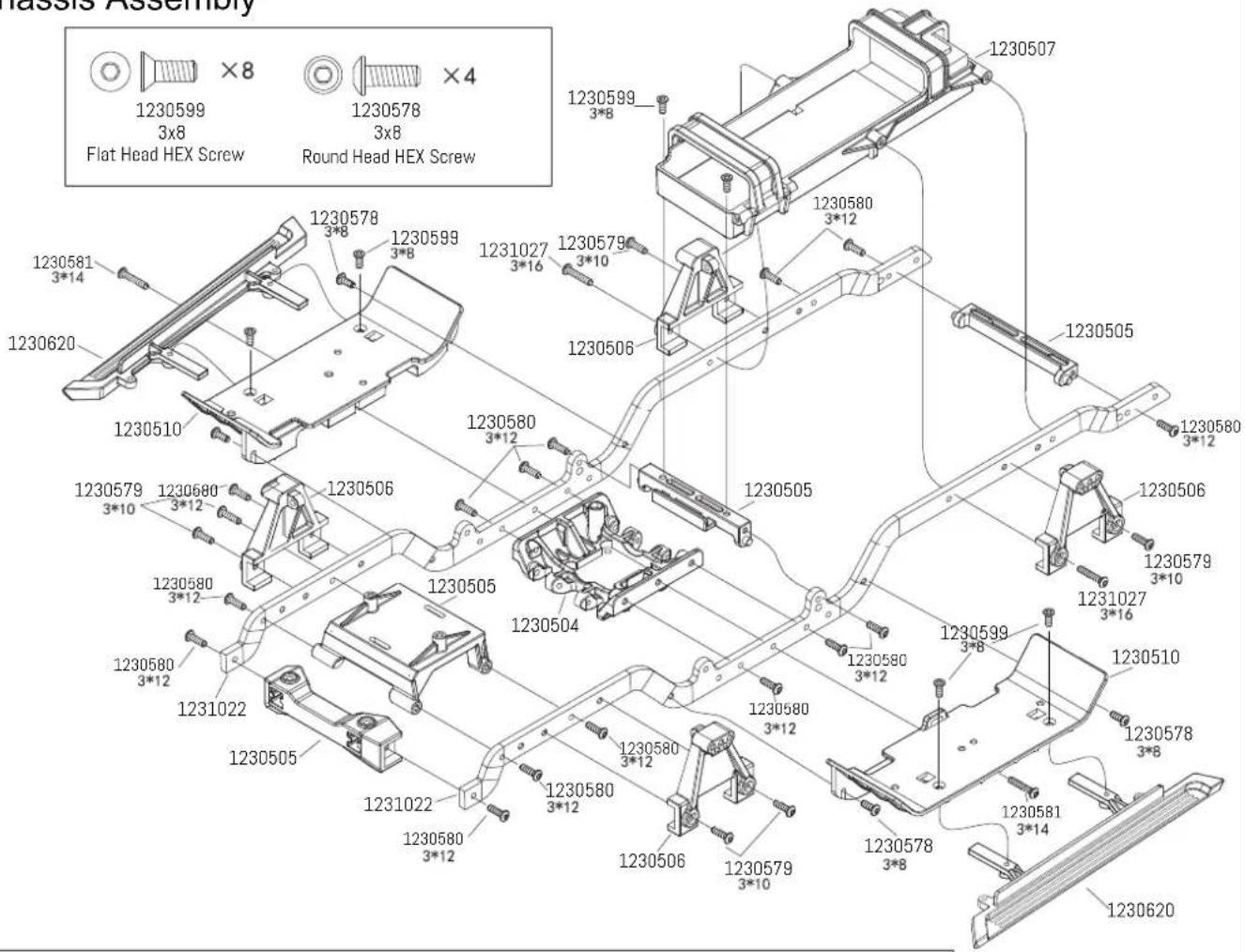
Chassis Assembly


1230599
3×8
Flat Head HEX Screw


1230578
3×8
Round Head HEX Screw


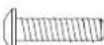
1230579
3×10
Round Head HEX Screw


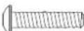
1230580
3×12
Round Head HEX Screw


1230581
3×14
Round Head HEX Screw

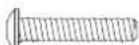

1230582
3×16
Round Head HEX Screw
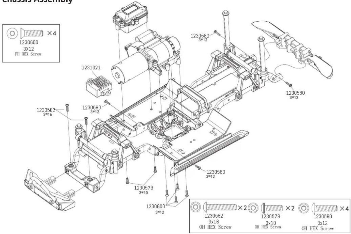
Chassis Assembly
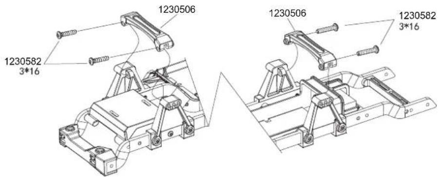

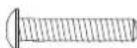
1230582
3×16
Round Head HEX Screw
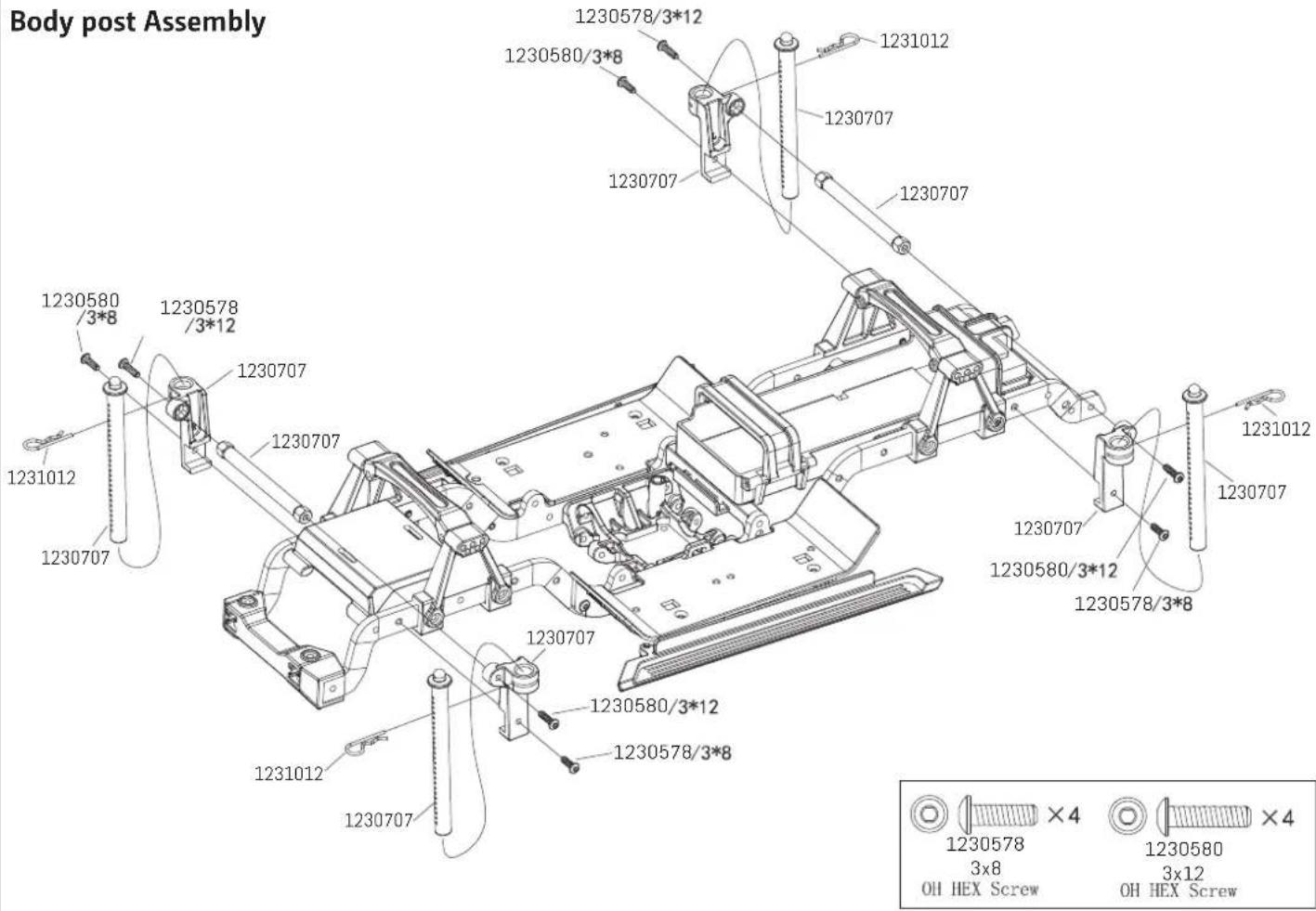
Chassis Assembly
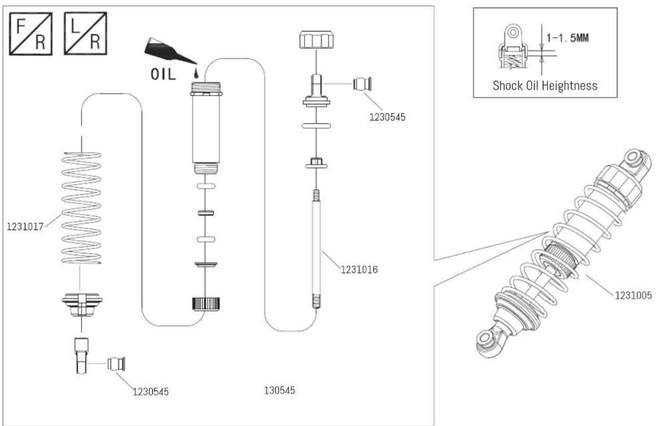
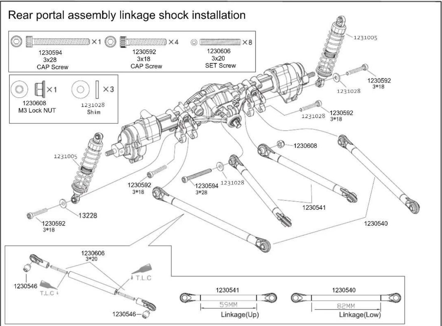
Shock Assembly
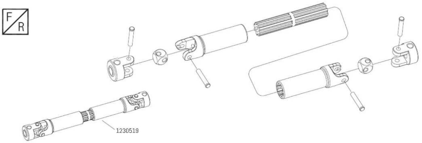
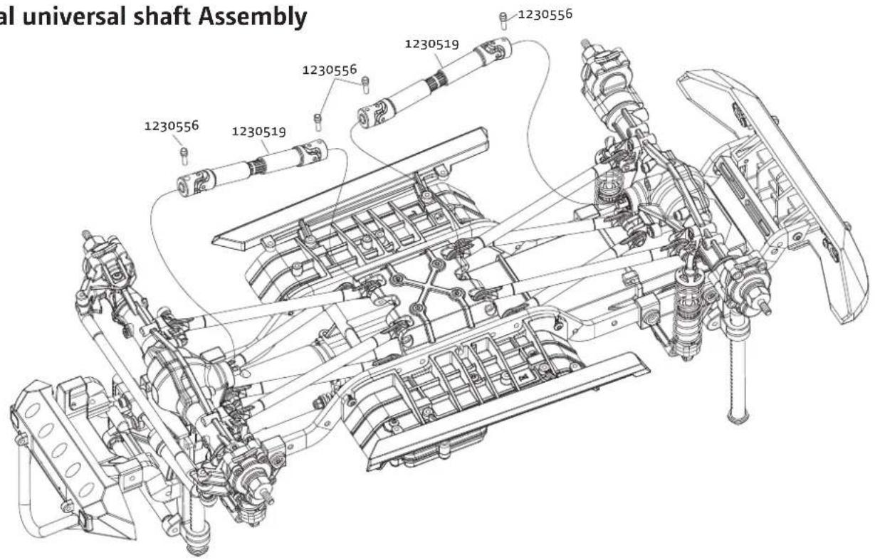
Vertical Universal Shaft Assembly
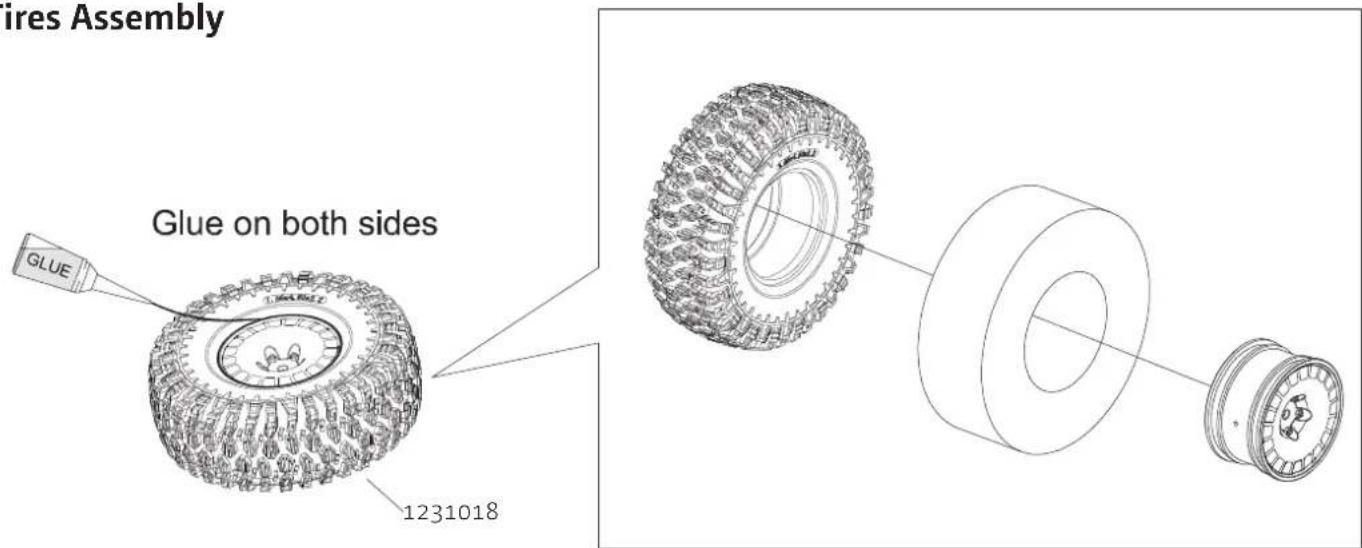
Tires Assembly
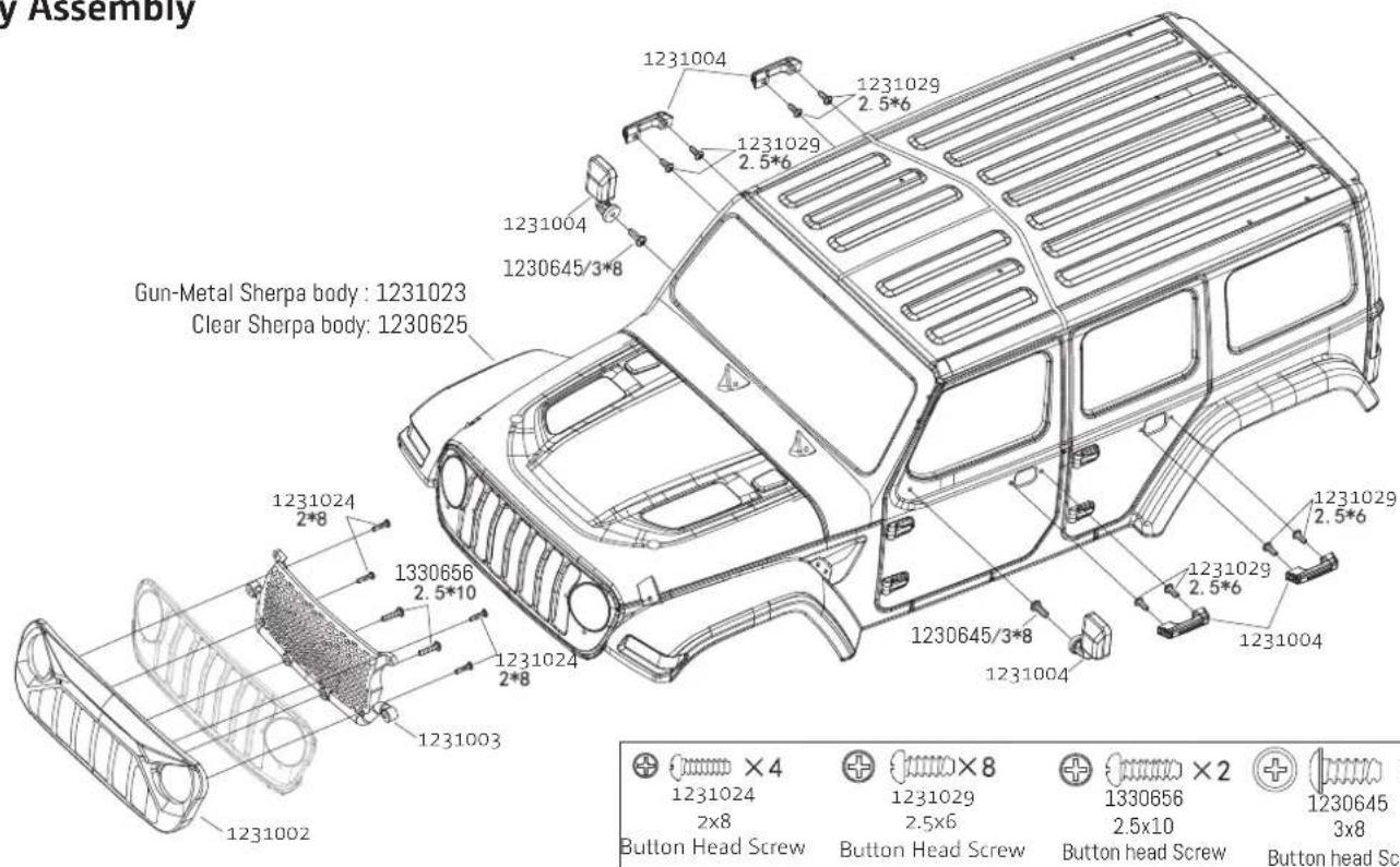
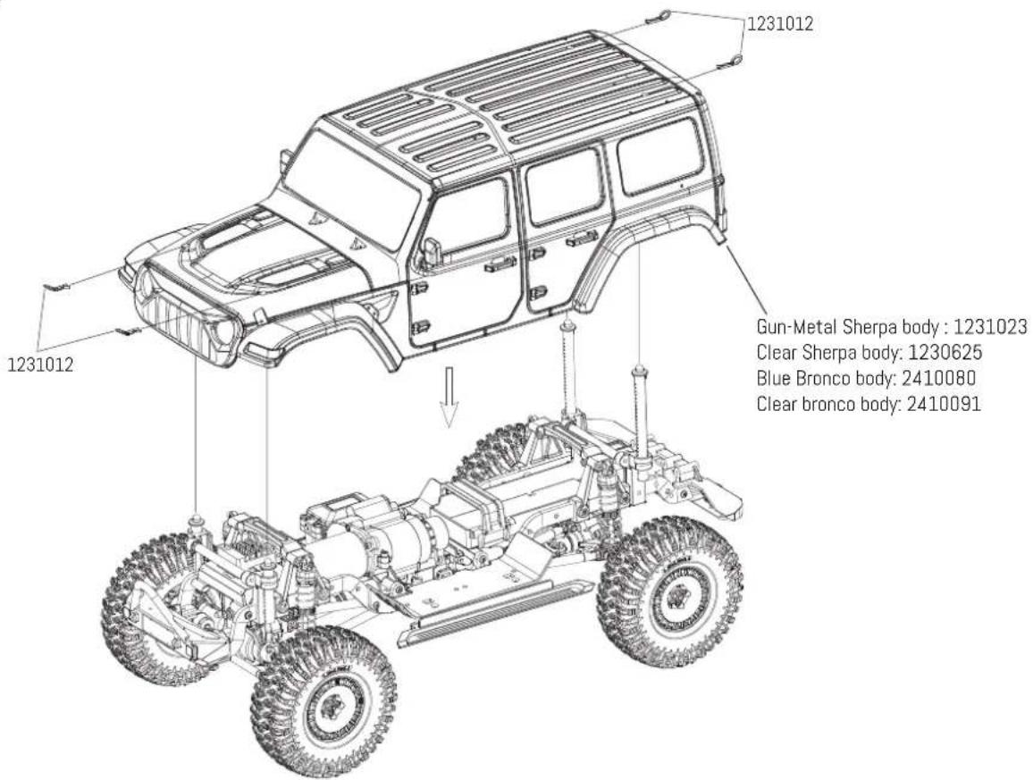
Body Assembly
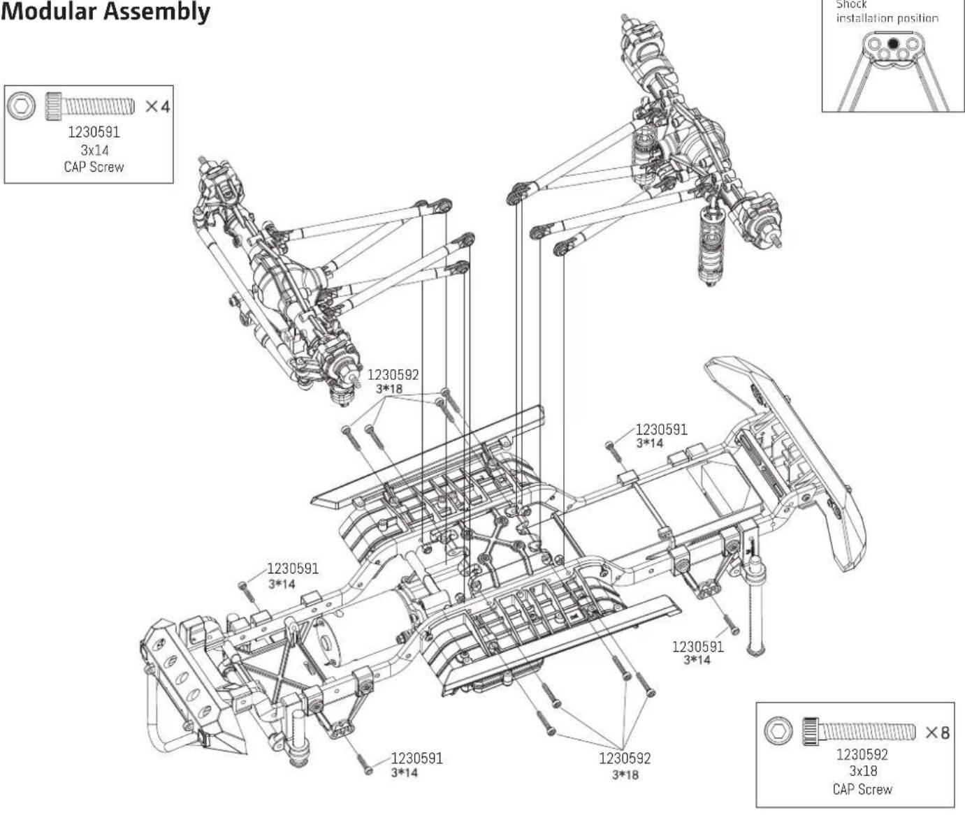
Modular Assembly
Vertical universal shaft Assembly
Tires Assembly
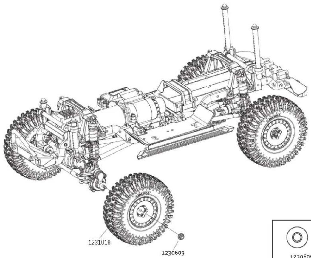


×4
1230609
M4 Lock NUT
Body Assembly
Spare Part List
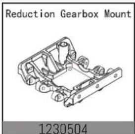
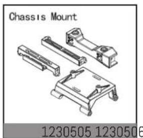
natural_image
Technical illustration of a chassis mount assembly (no text or symbols on the diagram itself)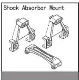
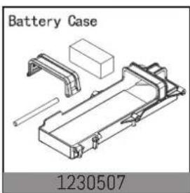
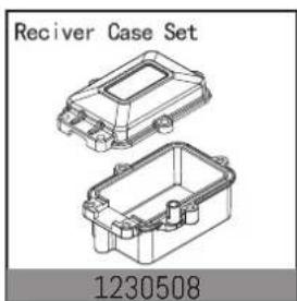
natural_image
Technical line drawing of two labeled electronic case sets (no text or symbols on the cases themselves)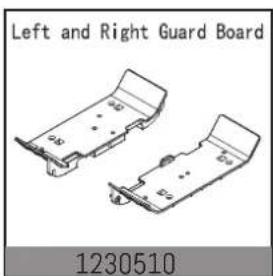
natural_image
Technical drawing of two mechanical components with no visible text or symbols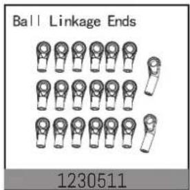
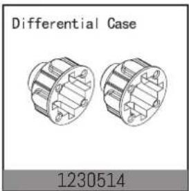
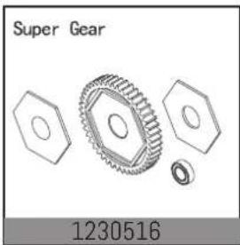
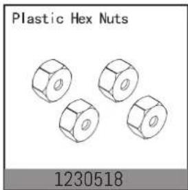
natural_image
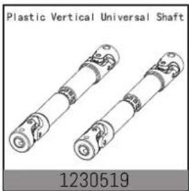
Two plastic vertical universal shaft components with no visible text or symbols on the shaft body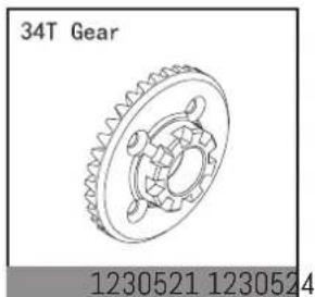
natural_image
Technical drawing of a 34T Gear component with no visible text or symbols on the gear itself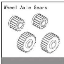
natural_image
Illustration of four different wheel axles (no text or symbols on the gears)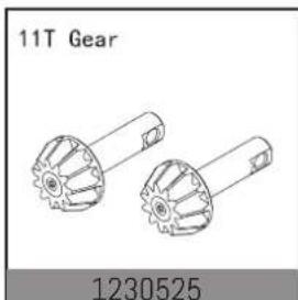
natural_image
Technical line drawing of two mechanical gears with no text or symbols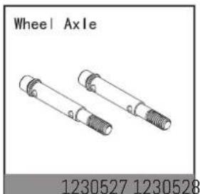
natural_image
Technical line drawing of two mechanical components labeled 'Wheel Axle' and part numbers 1230527 and 1230528 (no text or symbols on the components themselves)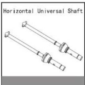
natural_image
Technical line drawing of a Horizontal Universal Shaft with two cylindrical components (no text or symbols)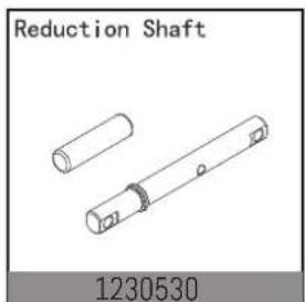

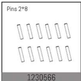
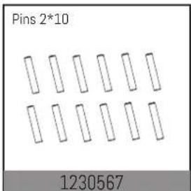
Spare Part List
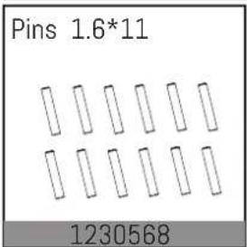
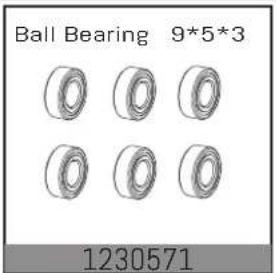
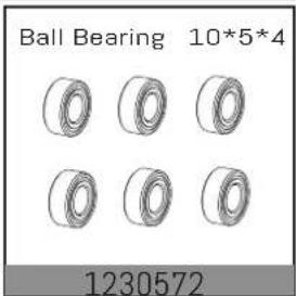
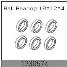
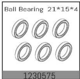
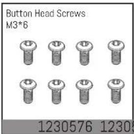
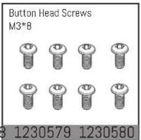
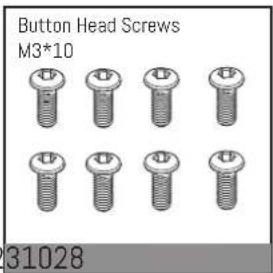
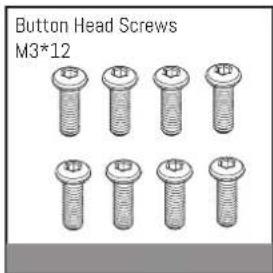
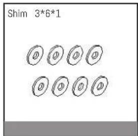
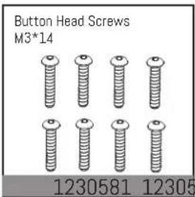

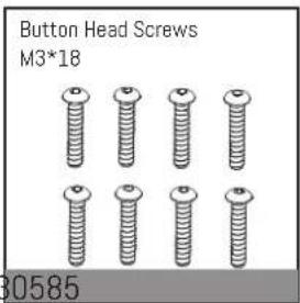
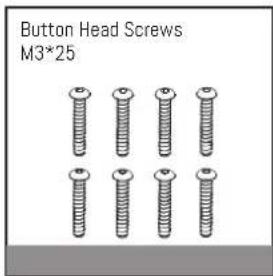
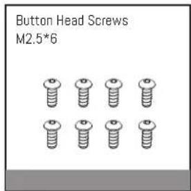
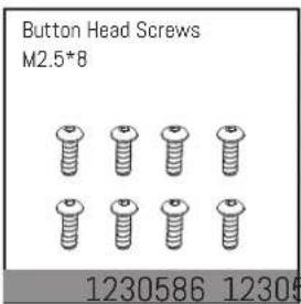
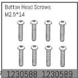
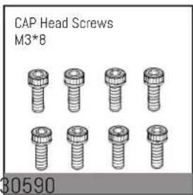
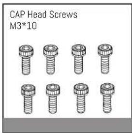
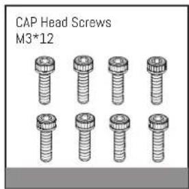
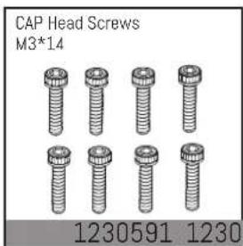
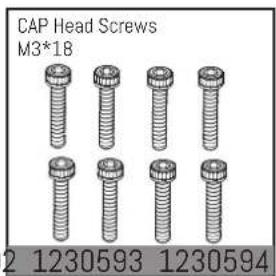
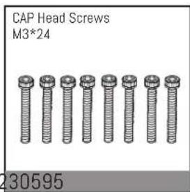
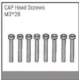
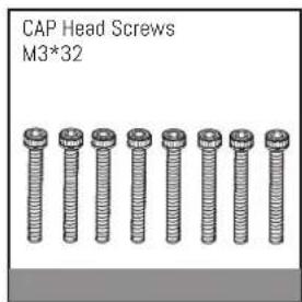
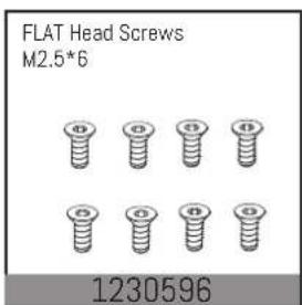
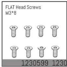
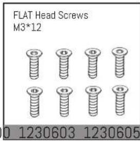
natural_image
Six identical cylindrical mechanical components arranged in two rows (no text or symbols)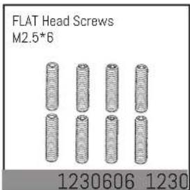

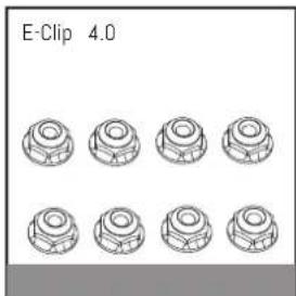
natural_image
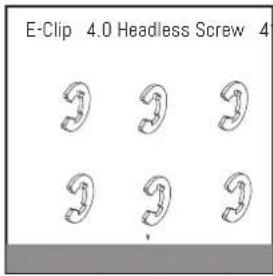
Diagram of eight circular mechanical components arranged in two rows, labeled 'E-Clip 4.0' at top (no other text or symbols)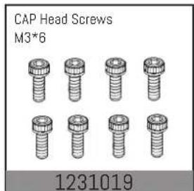
Spare Part List
Button head Self-Tappling Screw ST2*8
1231024 1231029
Button head Self-Tappling Screw ST2.5*6
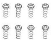
Button head Self-Tappling Screw ST2.5*10
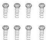
1230641
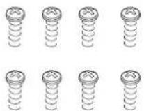
Button head Self-Tappling Screw ST3*8
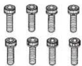
CAP head Screw M2.5*10
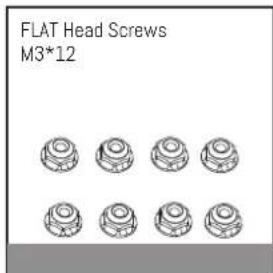
FLAT head Screw M3*6
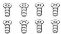
1231020 1230653
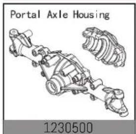
Portal Axle Housing
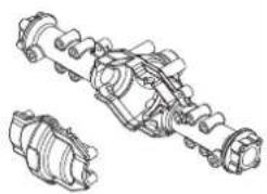
natural_image
Technical line drawing of a mechanical assembly with two views (no text or symbols)1330672 1231006
Rear Linkage Mount
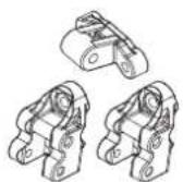
1231007
Ring gear set without differential
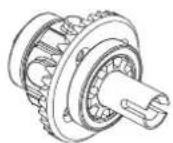
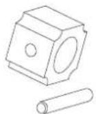
Driveshaft block
Outdrives
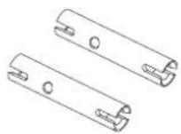
1231008 123063
Rear Driveshaft
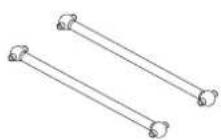
1230640 1231010
Rear wheel Axle
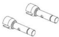
1231011
Motor Plate
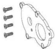
Motor Adjustment Plate

Rear Hub Set
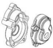
1230615 1230616
Rear axle connector
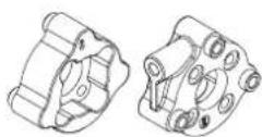
1231013 1231014
Servo Mount
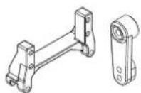
1231015
Reduction Gears
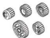
Transmission Gear Shaft
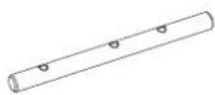
Reduction Shaft
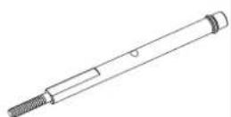
1231009 1231012
Body Clip
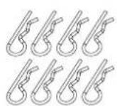
1231005 1231016
Damper
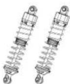
1231017
Shock Absorber Shaft
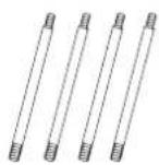
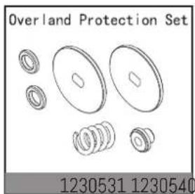
Shock Absorber Springs
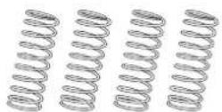
Body Mount Set CR 3.4
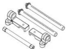
1230707 1231018
Tires wheel set
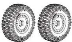
1231021
40A Brushed Speed controller
9kg Metal gear Servo
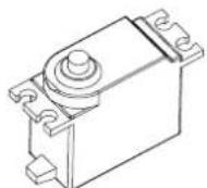
2040004 1231022
Chassis Frame
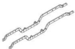
natural_image
Pure mechanical linkage diagram without any text, numbers, or symbolsGun-Metal Sherpa body
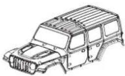
natural_image
Line drawing of a vehicle's front bumper frame (no text or symbols)1231023 1230625
Clear Sherpa body
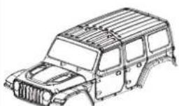
natural_image
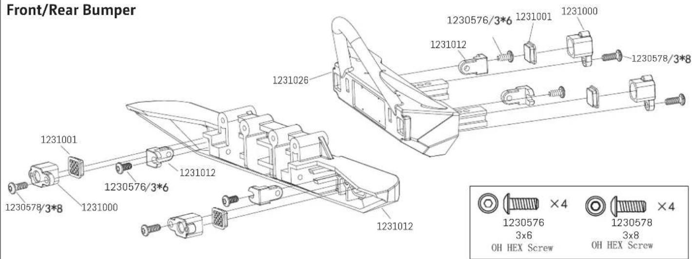
Line drawing of a vehicle chassis frame with no text or symbols1231026 1231000
Front And Rear Bummper
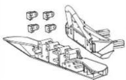
natural_image
Technical line drawing of a mechanical assembly with no visible text or symbols1231001
Lamp Cups
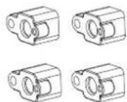
Lamp Shade
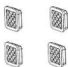
Spare Part List
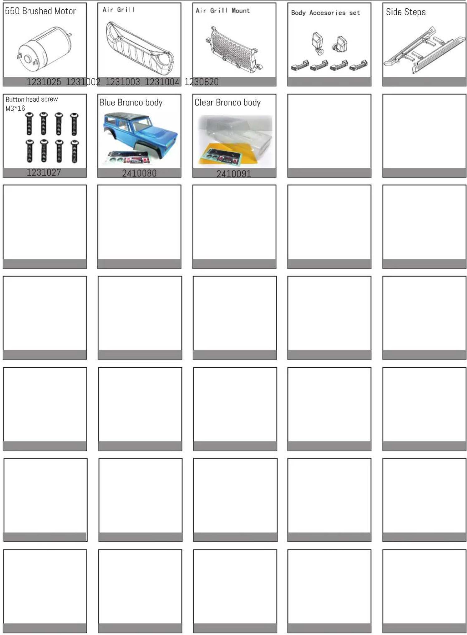
1231025 1231002
1231003 1231004
1230620
1231027
2410080
2410091
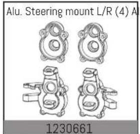
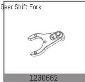
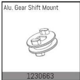
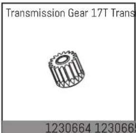
Upgrade Part List / Tuningteile
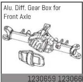
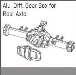
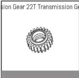
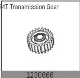
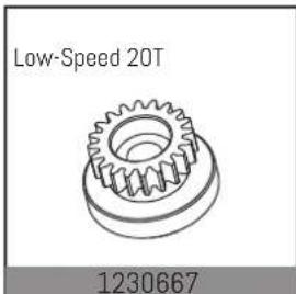
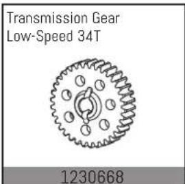
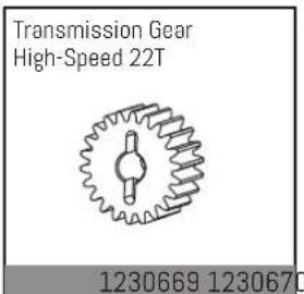
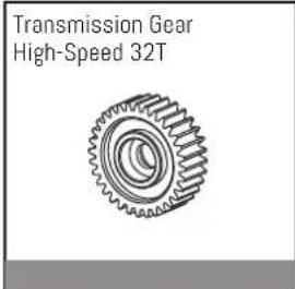
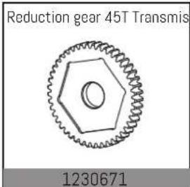
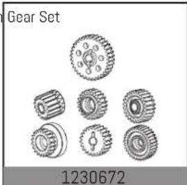
natural_image
Collection of mechanical gear components with no visible text or symbols on the gears themselves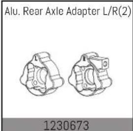
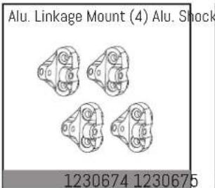
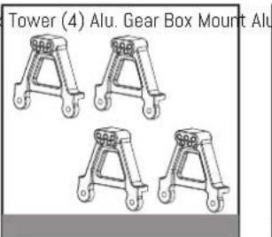
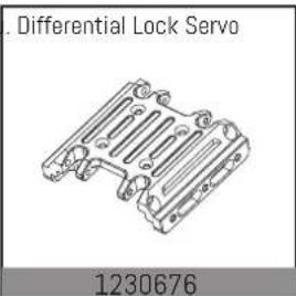
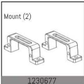
natural_image
Technical drawing of two mechanical bracket components labeled Mount (2) and 1230677, with no additional text or symbols present.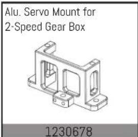
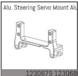
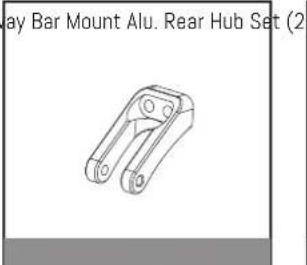
natural_image
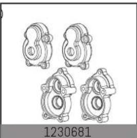
Technical line drawing of four mechanical bearing housing components (no text or symbols)
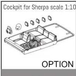
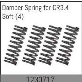
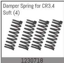
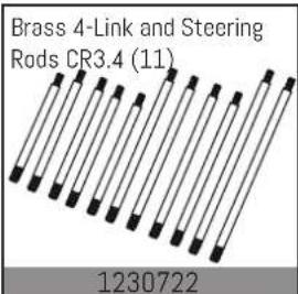
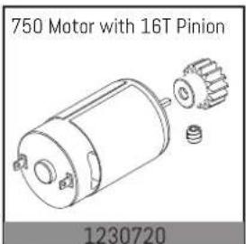
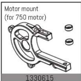
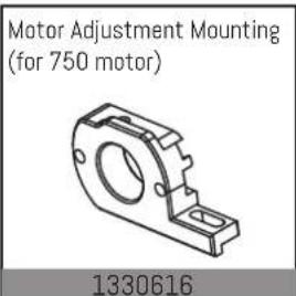
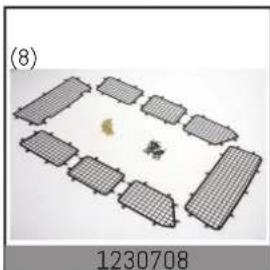
natural_image
Floor plan layout with grid-like compartments and a central circular object (no text or symbols)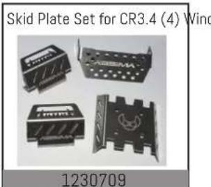
Upgrade Part List / Tuningteile

natural_image
Grid of 12 empty white squares with gray horizontal bars at the bottom, arranged in 3x3 pattern (no text or symbols)More add-on and tuning parts you will find at:
natural_image
Abstract black and white geometric symbol with interlocking curved shapes (no text or symbols)ABSiMA




- CR3.4 1:10 SCALE 4WD ELECTRIC CRAWLER eco
- Notiz
- ABSIMA
- Basic information for a safety operation of a rc model car.
- Before each driving:
- After each driving:
- Electric cars:
- Adjusting the distance between the motor pinion and main gear (if needed).
- Declaration of conformity
- General Information
- Getting Started:
- Always keep in mind:
- Please observe:
- Driving in wet conditions:
- Jumps:
- SAFETY INSTRUCTIONS ABSIMA RC CAR MODELS
- Necessary Service-features
- Warranty Terms
- Disclaimer
- Disposal
- INFORMATIONS GENERALES
- Sicherheit
- Safety Guide
- Prohibited
- Mandatory
- Introduction
- Receiver overview
- Accessories sold separately
- Getting Started
- Transmitter Battery Installation
- 4.Instructions
- Power On
- LED
- Binding
- Stick Calibration
- Power Off
- System Functions
- Channel Description
- Channel Reverse
- Trims
- D/R
- Mode switching
- Function setting:
- Failsafe
- Setup:
- Beginner Mode
- Certification
- Warranty Terms
- Disclaimer
- Declaration of conformity
- Disposal
- Sécurité
- ESC Specification:
- Set the ESC parameters:
- Protection Features:
- Spare Part List
- Upgrade Part List / Tuningteile
Brand : Absima
Model : CR3.4eco
Category : Remote control toy