
CR4T - Remote control Absima - Free user manual and instructions
Find the device manual for free CR4T Absima in PDF.


| Product Type | 4-channel radio control system for model cars and boats |
| Brand | Absima |
| Model | CR4T |
| Frequency Range | 2.40 - 2.48 GHz FHSS |
| Number of Channels | 4 (CH1-CH4) |
| Bandwidth | 500 KHz |
| Power Supply (Transmitter) | 4.8V - 6V (4x AA NiMH 1000 mAh included) |
| Power Supply (Receiver) | 4.0V - 6.5V |
| Range | >200 m |
| Dimensions (L x H x W) | 170 x 206 x 130 mm |
| Weight | Approx. 380 g |
| Low Battery Warning (Transmitter) | < 4.5V |
| Display Type | LCD Touchscreen |
| Programming Options | Reverse, End points, Subtrims, Exponential, Steering speed, Throttle curve, ABS, Mixes, Race timer, Key function, Model memory (20 profiles) |
| Telemetry Modules Included | Voltage, Speed (optical), Temperature |
| Binding | Digital binding via RX setup menu |
| Failsafe | Programmable servo positions on signal loss |
| Charging | Internal battery charger via micro USB (for firmware only); batteries charged externally |
| Languages | English, French, German |
| Safety Certifications | CE, complies with directive 1999/5/EC |
Frequently Asked Questions - CR4T Absima
User questions about CR4T Absima
0 question about this device. Answer the ones you know or ask your own.
Ask a new question about this device
Download the instructions for your Remote control in PDF format for free! Find your manual CR4T - Absima and take your electronic device back in hand. On this page are published all the documents necessary for the use of your device. CR4T by Absima.
USER MANUAL CR4T Absima
natural_image
Abstract green and black geometric logo design (no text or symbols)ABSIMA

natural_image
Black CR4T 24Hz Radio System ABSiMA controller with visible branding and control panel (no text-heavy elements)CR4T
2,4Ghz Radio System
Version 01/13

Index
Page
- Introduction....4
- Correct use....5
- Product description....5
- Scope of delivery ....5
- Symbols explanation....6
- Safety instructions....6
a) General....6
b) Operation....7
- Battery details 8
8 Charge batteries....9 - Radio controls....10
- Commissioning of radio.... 11
a) Insert and charge battery....11
b) Turn on the radio control....11
c) Test and setting the digital trim....12
- Commissioning of receiver....13
a) Receiver connection....13
b) Install the receiver....14
c) Install the servo 14
d) Binding function....15
- Install telemetry module .... 15
- Test the steering-, drive-, and shift function....16
a) Test the steering function 16
b) Test the drive function....17
- Programming the radio control....18
a) Programming the radio control....18
b) Symbol explanation....19
c) Handling the LC-Touchscreen Display....19
- Adjustments in the main menu....20
a) Adjustments main menu....20
b) Reverse 21
c) End points....22
d) Subtrims ....23
e) Steering exponential....24
f) Steering speed 24
g) Steering mix....25
Page
h) Throttle neutral....25
i) Throttle exponential 26
j) Throttle curve....26
k) A.B.S. 27
I) Throttle speed....28
m) Throttle middle position....29
n) Throttle idle up....29
o) Engine cut....30
p) Boat mode ....30
q) Brake mixing....31
r) Mixes....31
s) Display servos ....33
t) Race timer ....33
u) Key function....34
v) Models 35
w) RX setup 36
x) System....38
-
Service and support....39
-
Disposal....39
a) General....39
b) Batteries....39
-
Elimination of errors....40
-
Technical specifications....41
a) Radio....41
b) Receiver....41
- Declaration of conformity(DOC) 41
1. Introduction
Dear Madam, dear Sir,
Thank you for purchasing this product.
This product complies with the applicable national and European requirements.
To maintain this condition and to ensure safe operation, you need to request the user Manual!

This manual belongs to the product. It contains important information for handling the unit. Bear this in mind if you pass it on to third parties.
Keep these instructions for future reference!
All company names and products are trademarks of their respective owners. All rights reserved.
For technical questions, contact:
Fr. 8.00-15.00 o'clock
2. Correct use
The 4 channel radio control is designed exclusively for the private use in model range with the associated operating hours. Stand for a industrial use, for example the control of machines or installations, this system is not suitable.
A another use, described as previously, may damage the product.
The radio control system may not be technically modified or rebuilt! The safety instructions must be observed!

Follow all safety instructions in this manual. These contain important information about using the product.
You alone are responsible for the safe operation of your remote control and your model!
3. Product description
With the 4-channel radio control, you have a radio control system that is ideal for model cars and model boats. On the two proportional control channels the driving and the steering functions are independently operated remotely.
Additionally, there are two more switching channels is now accessible so you can use to serve special functions or manual transmission.
The ergonomically designed body fits comfortably in the hand and allows for convenient operation of the transmitter and the safe control of the model.
To operate the radio are AA Mignon batteries required. Unless a speed controller with BEC is used for the receiver, you need four AA batteries (Art.-No.: 4100030, 4er Pack, please order 1 time) or a Mignon accumulator.
4. Scope of delivery
- Radio control
- Receiver
• Voltage telemetry module
• Speed telemetry module (optical)
• Temperature telemetry module
• 4x AA NiMH Mignon batteries 1000 mAh 1,2V
5. Symbols explanation

The icon with an exclamation point indicates a particular risk associated with handling, operation and control.

The "arrow" icon puts everyone in special tips and operating information.
6. Safety instructions

Damages caused by non-compliance with these instructions will invalidate the warranty / guarantee. For damages we take no liability!
For property damage or personal injury caused by improper use or failure to observe the safety we take no liability! In such cases, the warranty / guarantee expires.
Excluded from the warranty and guarantee is normal abrasion during use and accidental damage (for example broken receiver antenna, broken receiver housing, etc.).
Dear Madam, Dear Sir,
these precautions are not only for protection of the product, but also for your own safety and that of other people.
Read therefore, this chapter very carefully before using the product in use!
a) General

Attention, important note!
During the operation of a model can lead to property damage or personal injury occur.
Therefore make sure that you for the operation of the model are adequately insured as available via a liability insurance. If you already have one, so check before commissioning of the model with your insurance company, if the operation of the model is covered.
- For security and admission (CE) the unauthorized conversion and/or modification of the product is not allowed.
- The product is not a toy and is not suitable for children under 14 years.
• The product must not becoming wet or damp. - Plug in electric models on the drive motor only after the complete installation of the receiving system. To prevent the drive motor suddenly starts unintentionally.
-
Do not leave the packaging material lying around, this could be dangerous for children.
-
Check that they are before putting into operation the reliability of your model and the remote control system.
Look out for any signs of damage, such as faulty connections or damaged cables. All moving parts have to function smoothly, but no play in the main in storage have. - If questions arise that can not be ascertained with the help of the manual, please contact with our "technical advice" (contact information, see Chapter 1) or other qualified installer.

The operation and use of radio controlled models must be learned! If you have never seen a remote controlled model, so start very careful and be familiar with the reactions of the model on the remote control commands. Have patience!
b) Operation
- Shouldn't they feature sufficient knowledge available via the use of radio-controlled models, please contact an experienced modeller or a model club.
- First, turn on the transmitter. After that turn on the receiver. Doing so may cause, unpredictable reactions of the model! Angles from the side of the transmitter antenna to the model, so as to obtain an optimal radiation of transmitter signals. Avoid placing the antenna on top of the model.
- Check before operating on the stationary model, whether it is responding as expected to the remote control commands.
- When operating a model, always make sure that never, body parts or objects within the range of motors or other moving drive components are located.
- Improper operation may cause serious injury and damage to property! Always maintain direct eye contact with the model, and therefore does not operate at night.
- Control your model only if your reaction is given indefinitely. Fatigue, alcohol or medication can influence lead to incorrect responses.
• Always operate your model in an area where you do not endanger other people, animals or objects. Use the device on private or specially designated for that purpose. - Set the operation of your model in the event of a fault, and correct the cause of the malfunction before using the model further.
- Don't run your remote control system during a thunderstorm, under power lines or near cell towers.
- Always leave the remote control on (transmitter), while the model is running. After the race, always turn off the motor an after that turn off the remote control. Only then the remote control transmitter is turned off.
- Protect your remote control from wetness and heavy contamination.
- Don't place the transmitter a long time directly in the sun or extreme heat.
- Low batteries (or rechargeable batteries) in the remote control decreases the range. If the receiver battery is low, the model does not respond correctly to the remote control.
☒ In this case, stop the driving immediately. Then replace the batteries with new ones or recharge the batteries.
- Be careful when operating the product! Their own safety and that of your environment depend alone on your responsible use of the model.
7. Battery details
- Batteries / rechargeable batteries out of reach of children.
- Don't leave batteries / rechargeable batteries open, there is a risk that can be swallowed by children or pets. In such a case, contact a doctor immediately.
- Don't shorting the batteries / rechargeable batteries or throw into fire. Danger of explosion!
- Leaking or damaged batteries / rechargeable batteries can cause acid burns, you therefore use suitable protective gloves.
- Conventional batteries from maintaining not be charged. Risk of fire and explosion! Only charge batteries provided instead, use suitable rechargeable battery chargers.
- Pay attention when inserting the batteries / rechargeable batteries on the correct polarity (postive + / negative -).
- Remove the batteries / rechargeable batteries of the remote control and of the model when not in use. This is to avoid damage due to leak of batteries.
☒ Recharge your battery every 3 months, since this can come through the self-discharge to a so-called deep discharge, so that the battery may become unusable.
- Always replace the whole set of batteries or rechargeable batteries. Do not mix complete with half-full batteries / rechargeable batteries. Always use batteries of the same type and manufacturer.
- Never mix batteries with rechargeable batteries! Use for the remote control batteries or rechargeable batteries.

The lower capacity of battery leads to a reduction of the operating time. This usually plays no role, since the operating time of the transmitter is widely available via the model.
When using rechargeable batteries can cause a loss of range.
8. Charge batteries
Required for the remote control battery is normally upon delivery empty and needs to be recharged.

Please note:
Before a battery that offers maximum performance, several complete discharge and recharge cycles are required.
Discharge the batteries at regular intervals, as may occur when multiple charging a "half-full" batteries for so-called memory effect. This means that the battery will lose its capacity. It is no longer the entire energy stored in the operating time of the model or of the transmitter is lower.
If you use multiple batteries, may be worth buying a quality charger. This usually offers a quick charge for battery.
9. Radio controls
- LCD-Touchscreen-Display
- TR1 (exponential function throttle/brake)
- TR4 (exponential function steering)
- TR5 (channel 3)
- SW1 (channel 3)
- SW2 (channel 4)
- POWER (on/off)
- SW3 (A.B.S.)
- TR3 (trim throttle/brake)
- Steering wheel
- TR2 (trim steering)

Picture 1.a
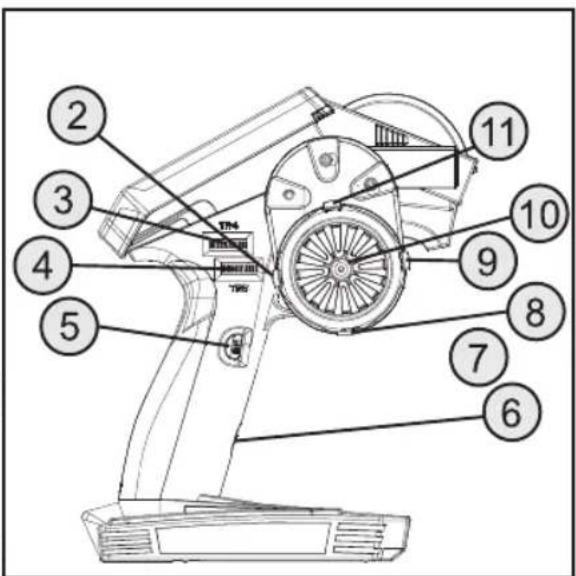
Picture 1.b
- Micro USB-connection
- Throttle/brake lever

Picture 2
10. Commissioning of the radio

Later in the guide, the numbers in the text always on the adjacent image or the images within the section. Cross-references to other pictures are given with the corresponding image number.
a) Insert the battery
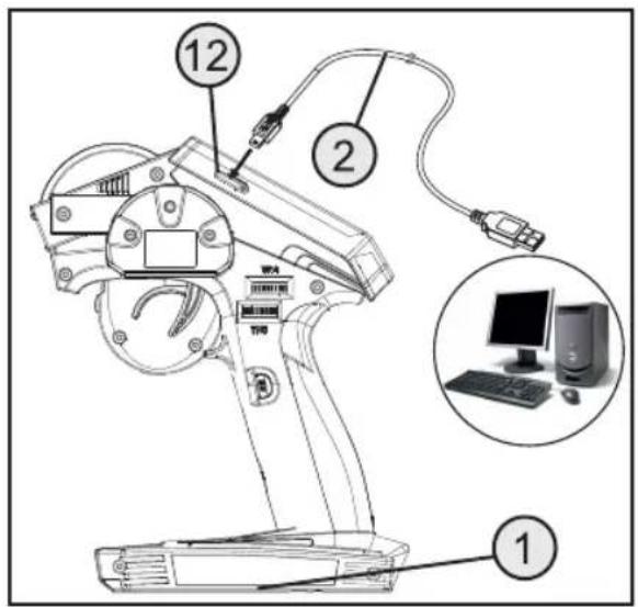
The battery cover (1) is located on the bottom of the transmitter. Please push on the ribbed surface and slide off the cover. Finally, the battery can be inserted. Slide the battery compartment cover (1) back onto the battery compartment. The cover must audibly lock.
Connect a Micro USB cable (2) into the micro USB port (12) of the transmitter. The other end of the micro-USB cable (2) should be connected to USB port of a computer, only for firmware update or emulator.
Picture 3
b) Turn on the radio control
If the battery is charged, turn on for testing the transmitter via the power button (see Figure 1.a, Item 7). To save power, the backlight turns off after turning on about 3 seconds. Only when any key or the LCD touch-screen display are pressed, the light switches on for about 3 seconds later.
c) Test and setting the digital trim
Before operate adjustments to their model or start programming your product, you need to make sure that the digital trim for the steering and driving function is in the central position (0).
Center position of the steering function
With the trim button (TR2) for the steering function, the center position for the steering servo will be adjusted (ST). Press therefor the trim button (TR2) to either the left or right to set the value to 0. If you hold the trim button pressed, the value is changed continuously. The adjustable value is between left and right in each case maximum 30.

Picture 4

Each press of the programming and control keys is confirmed by an acoustic signal.
If a button is pressed longer, the values change continuously and the product are made sounds in quick succession.
Center position of the driving function
With the trim button (TR3) for the steering function, the center position for the throttle servo will be adjusted (TH). Press therefore the trim button (TR3) either to the left or right to set the value to 0. If you hold the trim button pressed, the value is changed continuously. The adjustable value is between left and right in each case maximum 30.

Each press of the programming and control keys is confirmed by an acoustic signal.
If a button is pressed longer, the values change continuously and the product are made sounds in quick succession.

Adjust the average exactly even then, if you are replacing a throttle-servos through an electronic speed controller.
11. Commissioning of the receiver
a) Receiver connection
The receiver provides connectivity for up to four servos (CH1, CH2, CH3, CH4) and a receiver battery (B/VCC).
Always pay attention the correct polarity of the connector when you connect the servos. Plug contact for the pulse line should be on the inner (left) pin connected (depending on the manufacturer of yellow, white or orange). Plug contact for the negative line should be in the outside (right) pin connected (depending on the manufacturer black or brown).
Turn on the transmitter and then the receiver. If correctly binding function, the red LED indicator on the receiver flashes. Check the correct function of the receiver and then turn it off again.

If the LED doesn't flash or the servos have no function, you have to do the binding process. For more information you can read about in the next section "Binding function".

flowchart
graph TD
    A["Device"] --> B["BVCC"]
    B --> C["CH4"]
    C --> D["CH3"]
    C --> E["CH2"]
    C --> F["CH1"]
    D --> G["Component 1"]
    D --> H["Component 2"]
    D --> I["Component 3"]
    D --> J["Component 4"]
Picture 5
Require in addition to the steering servo on receiver output "CH1" and the throttle servo/speed controller receiver output "CH2" can be connected additional a servo to receiver output "CH3". This servo takes at the push of a button functions on the transmitter.
In an electric model with mechanical speed controller is for the power supply of the receiver a battery box or a separate receiver battery required. The power connector which is mounted on the mechanical speed controller must not be used because the voltage at the plug from 7.2 V (at 6 cell battery) is too high for the receiver and the servos.
In an electric model with electronic speed controller is a separate receiver battery for port „B/VCC“ required if the used motor controller has no BEC-circuit. For more information, please refer to the technical documentation of the controller.
b) Install the receiver
Installation of the receiver is always dependent on the model. Therefore, you should follow with respect to the incorporation of the recommendations of the manufacturer's model.
In general, you should always try to position the receiver so that it is optimally protected from dust, dirt, moisture and vibration. Suitable for mounting double-sided adhesive foam or rubber rings that hold the receiver in foam wrapped securely in place.
Drove the antenna wire directly out of the model.

The antenna wire of the receiver has a precisely measured length. For this reason, the antenna wire do not wound, laid in loops or cut. The range of the transmitter would be severely limited and has been pose a significant security risk.
c) Install the servo
The installation of a servo is always dependent on the used model. Detailed information is given in the manual of the model.
Of hard to process rowing servos and linkages can not run into the required position. They consume electricity unnecessarily, and the model has an unclean control behavior.
Mount the servo arm always at a 90^ angle to the steerin linkage. In an angel to the pushrod standing servo arm are not both control directions must be equal.

Make sure before installing the servo arm for the drive and steering function that the trim function of the respective channel is in the center position. For more information, see the section "Setting and check the digital trims" manual.
The servo arm to channel 3 (CH3) must be mounted so that it can run when switching from one end to the other ..
d) Binding function
Thus, the transmitter and receiver can communicate with each other, you need through the same digital code are bound together. When delivered, the transmitter and receiver already matched and can be used immediately. The renewal of the binding function is primarily required for a transmitter or receiver changes or to correct faults.
If a new connection between the transmitter and receiver may be necessary, please proceed as follows:
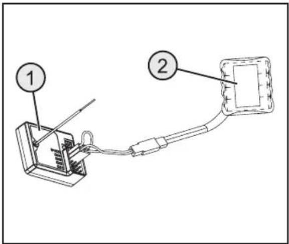
Unplug all servos from the receiver. Turn on the transmitter. Then open the main menu and select the submenu "RX setup". Now select the function
"Bind with a receiver". Connect a battery to the receiver and the corresponding BIND cable insert at (B / VCC). The LED on the receiver will flash briefly.
Picture 6
The transmitter ends the binding function when a secure connection has been established. Now unplug the battery from the receiver and plug in the servos. After that make a restart to make sure that every servos works well.
12. Install telemetry module
a) Install a speed telemetry module
The receiver allows you to connect a speed sensor on the model. For this purpose you need to draw a line on the rotating part with a permanent marker. If a white rim is installed, you have to draw a black line.
The distance between the line (3) and the sensor (2) may not be larger than 2 mm. The line (3) must be parallel to the sensor (2). The line must have the width of the sensor.
Once you have turned on the transmitter and receiver, the message "engine speed RPM 2:0" is on the LCD screen. Then open the main menu and select the submenu "RX setup". Now select the function "Speed and distance". Set this to the circumference of the tire, so that the speed sensor is working properly.

Picture 7
b) Install a voltage telemetry module
Connect the red and the black connector directly to the battery, or the battery balancer.
The red wire is positive and the black wire is negative. If you have connected the connector correctly, the display will show "Ext voltage2": and the voltage.
c) Install a temperature telemetry module
Connect the temperature sensor to a component which can be warm. The display will show "Temperature 2" and the respective temperature.
To connect the respective sensors you need the included black / white / red wire in the plug "IN" input on the receiver and plug the sensors in the "OUT" output. To connect more than one telemetry module, simply plug the cable continuously in the respective inputs of the sensors.
13. Testing the steering-, drive-, and shift function

Place the model on a suitable base (wooden block or similar) to test the steering and handling functions. The wheels should rotate freely.
a) Test the steering function
For the testing turn on the transmitter and the receiver. If you did everything correctly connected and installed, the steering should respond to the rotary motion of the steering wheel.
When the steering wheel is in the middle position, the wheels need to be aligned.
If the wheels are at an angle, even though the steering wheel is in the center position, you also check whether the servo arm to the steering linkage is wrong.
In this case, disconnect the servo arm and screw it on a "teeth" offset again.
If necessary, other variations of the wheel positions can be corrected by adjusting the steering linkage.
If you steer left, the wheels have to turn to the left. If you steer right, the wheels have to turn to the right.

natural_image
Top-down view of a CRL-T robotic vehicle with front-mounted sensor and two side-view diagrams showing internal components (no text or symbols)Picture 8

If the control direction exactly opposite to react to control, you can easily re-program the direction of the transmitter. See therefor in the chapter "Selection of Menus" and then "Reverse".
b) Test the drive function
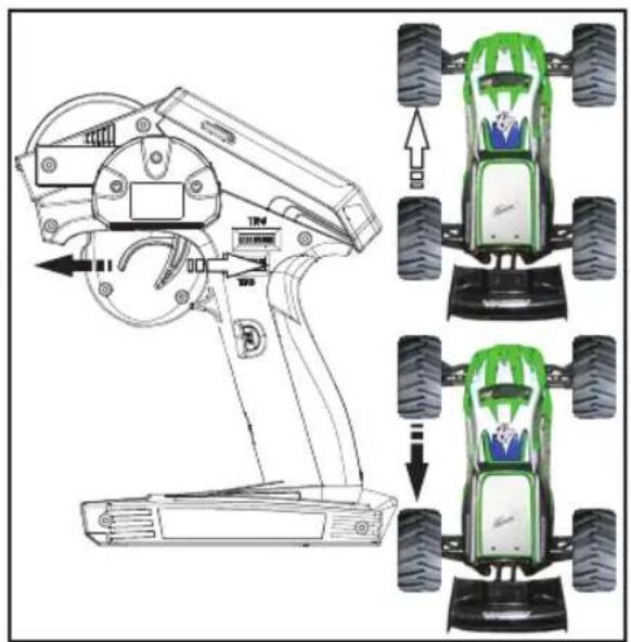
To accelerate the model you have to pull the throttle/brake trigger in the direction of the handle.
To decelerate the model you have to push the throttle/brake trigger in front of the handle.

If the control direction exactly opposite to the direction of the transmitter control you can easily re-program. See therfor in the chapter "Selection of Menus" and then "reverse".
Picture 9
14. Programming the radio control
a) Programming the radio control
This product offers you the opportunity to tune the ride, steering and control functions of your model individually and save the values stored permanently. Only an adjusted to the rider's model offers maximum driving pleasure.
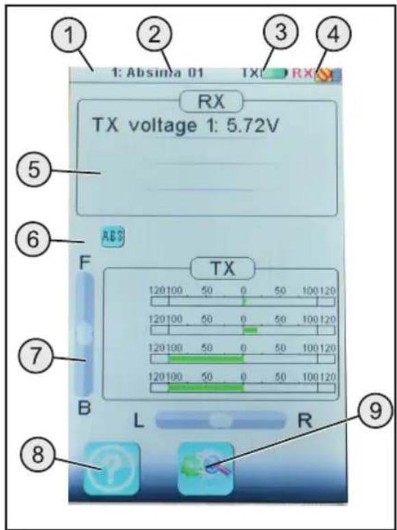
The command of the product is carried out via the touch screen display. Once you turn on the product, the following informations are on the LCD display:
- Receiver signal
- Profile
- Radio contorl battery
- Receiver battery
- Receiver status
- Settings
- Radio control status
- Help
- Main menu
Picture 10
b) Icon explanation
| Icon | ||
 | Main menu This icon will take you to the main menu, where you can program your product individual. | |
 | Back This icon allows you to return back to the previous menu. | |
 | Activate/Deactivate | With these icons you activate or deactivate your customizations. |
 | Re-establish This icon restores the factory setting of the customized menu point. | |
 | Help Use this icon to call up the help function (only German, French and English). | |
 | Control This icon restores individually the selected parameters. | |
c) Handling the LC-Touchscreen-Display
By hand or with a suitable pen you can select for the operation of a LCD touchscreen display the individual menu items and adjust the values. The selected parameters are always highlighted in yellow.

Thus, the LCD screen protect from being scratched, we recommend the use of a suitable pen for the operation of the LCD.
15. Adjustments in the main menu
a) Adjustments main menu
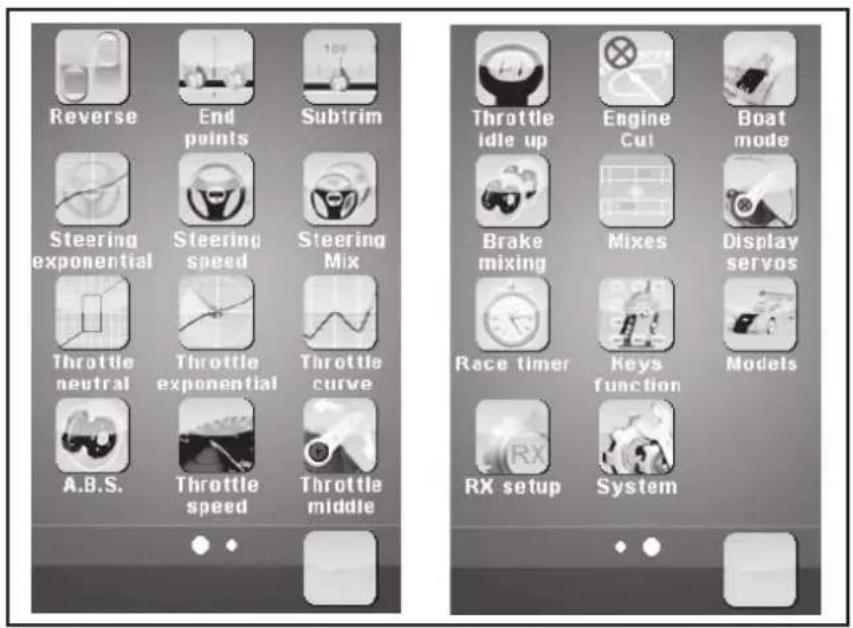
Turn on the transmitter and select the main menu. The following setting options are at your disposal:
Picture 11
b) Reverse
With this function, you can change the direction of servo rotation of all four channels (CH1 to CH4). Depending on the installation location and linkages in the model, it may be necessary to change the direction of rotation of the servo.
Tap therfor the controller to change the servo direction of the desired channel from normal (NOR) to Reverse (REV).

Picture 12
c) End points

Picture 13
This feature allows you to specify how large can the maximum allowable deflection for the steering, gas or auxiliary power is on each side. This function is normally used to protect the servos at full deflection before the mechanical abutment set in. You can use a value between 0 - 120%. The smaller the value, the smaller the servo travel on the relevant page.
Set the value for the steering servo (CH1)
On channel 1 (CH 1) you can set the maximum possible driving rash. Select therefor the parameter to change to the appropriate stop side (left or right). Move the controller to the right or left to adjust the value according to your wishes. Tap the button "back" in order to save the changes and return to the menu.
Set the value for the throttle servo (CH2)
On channel 2 (CH2) you can set the maximum motor speed. Select therefor the parameter to change to the appropriate stop side (left or right). Move the controller to the right or left to adjust the value according to your wishes. Tap the button "back" in order to save the changes and return to the menu.
Set the value for add-on servos (CH3 and CH4)
On channel 3 (CH3) and channel 4 (CH4) you can set the value for add-on servos. Select therefor the parameter to change to the appropriate stop side (left or right). Move the controller to the right or left to adjust the value according to your wishes. Tap the button "back" in order to save the changes and return to the menu.
d) Subtrims

Picture 14
This feature allows an individual adjustment of the center position of the driving and steering servo. A slight pull to the left of the model can be compensated/corrected with the help of trim. Thus the correct straight is ensured when the steering wheel is on the transmitter in the central position.
Select therefor the parameter to change. Move the controller to the right or left to adjust the value according to your wishes. Tap the button "back" in order to save the changes and return to the menu.
e) Steering exponential
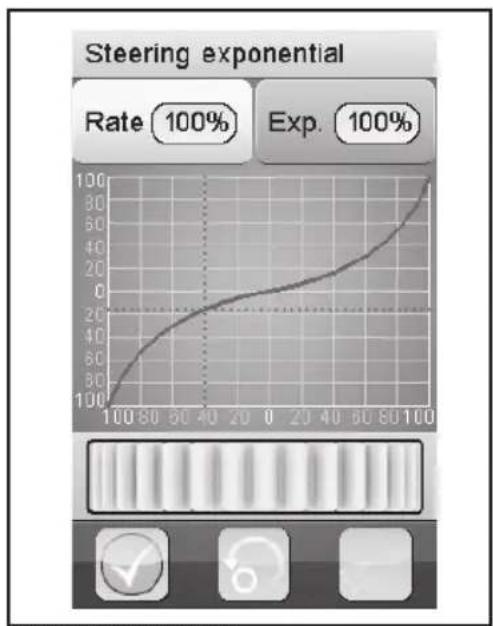
This feature allows you to influence the steering sensitivity. Thereby the linear distance between the transmitter control and servo is changed in a non-linear (exponential) way. A fine control to the neutral position is possible. The maximum control path is not changed.
„Exp.“:
The setting value is -100% to 100% , wherein the value corresponding to 0% of the linear control. A change of the set always affects simultaneously on both sides of the servo rash.
„Rate“:
Here, the slope of the curve is set. The adjustable value for the slope of the curve is 0% to 100%. The smaller the increase, the smaller the steering.
Select the button "activate". Select therefor the parameter to change. Move the controller to the right or left to adjust the value according to your wishes. Tap the button "back" in order to save the changes and return to the menu.
line
| Rate | Exp. | |------|------| | 100% | 100% |Picture 15
f) Steering speed
This function allows the speed of the steering servo perfectly match your model. When not setting the steering servo, threatened a loss of control of your model.
„Turn speed“:
The adjustable value for the turn speed is 0% to 100%.
„Return speed“:
The adjustable value for the return speed is 0% to 100%.
The values in the LCD display are shown in real time. The red bar represents the position of the steering wheel, the green bar represents the position of the steering servo.
Select therefor the parameter to change. Move the controller to the right or left to adjust the value according to your wishes. Tap the button "back" in order to save the changes and return to the menu.

Picture 16
g) Steering mix
This function allows you to set four different steering modes on the model.
„Front side“:
Only the front wheel steering is controlled.
„Rear side“:
Only the rear wheel steering is controlled.
„Same Phase“:
Front and rear wheels are equal sorted controlled.
„Rev. Phase“:
Front and rear wheels are driven oppositely.
Select the parameter to be changed to adjust the desired steering mode. Tap the button "back" in order to save the changes and return to the menu.

Picture 17
h) Throttle neutral
This feature allows to set the behavior of the throttle/brake trigger near its neutral position.
"Forward":
Here the point is defined at which the model begins the operation of the acceleration.
„Dead zone“:
Here the size of the neutral position is defined in which the throttle/brake trigger elicits no response.
„Backward“:
Here the point is defined at which the model begins upon actuation of the braking.
Select therefor the parameter to change. Move the controller to the right or left to adjust the value according to your wishes.
Tap the button "back" in order to save the changes and return to the menu.

line
| Position | Value | |--------|-------| | Forward | 30% | | Dead zone | 20% | | Backward | 40% |Picture 18
i) Throttle exponential
This feature allows you to influence the sensitivity of the throttle/brake servos. Thereby the linear distance between the transmitter control and servo is changed in a non-linear (exponential) way. A fine control to the neutral position is possible. The maximum control path is not changed.
„Exp.“:
The adjustable value of this function is -100% to 100%, wherein the value corresponding to 0% of the linear control. A change of the set always affects simultaneously on both sides of the servo rash.
„Rate“:
Here the slope of the curve is set. The adjustable value for the slope of the curve is 0% to 100%.
Select the button "activate".
Select therefor the parameter to change. Move the controller to the right or left to adjust the value according to your wishes.
Tap the button "back" in order to save the changes and return to the menu.

line
| Rate | Exp. | |------|------| | 100% | 40% |Picture 19
j) Throttle curve
This feature allows you to adjust the throttle response of the throttle/brake servos in a 5-point curve. Each point, you can adjust independently. Adjustable are values from -100% to 100%
Select the button "activate".
Select therefor the parameter to change. Move the controller to the right or left to adjust the value according to your wishes. Tap the button "back" in order to save the changes and return to the menu.
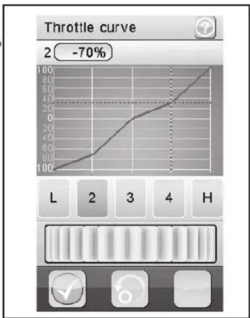
line
| Point | Value | |-------|-------| | L | 100 | | 2 | 80 | | 3 | 60 | | 4 | 40 | | H | 20 |Picture 20
k) A.B.S.

Picture 21
This feature allows the wheels from locking during braking by automatically pulsing (opening and closing the brakes) to prevent. Thus it is possible to retain the control over the model even during heavy braking.
„Brake return“:
This determines how far the brake is released with each impulse. At 100%, the brake opens completely and the brake servo returns after each pulse back to its neutral position. A value of 0% will be deactivate the "ABS function."
„Delay“:
Here can be set a time delay between the initiation of the "ABS" and the start of the braking action. A value of 0% means no delay, a value of 100% means a delay of approximately 2 seconds.
„Cycle length“:
Here can be determined the duration of an ABS braking period (closed brake, brake open). A value of 20% corresponds to about 100 ms, a value of 100% corresponds to about 500 ms.
„Trigger point“:
Here can be set a trigger point for the "ABS" function. The higher the value is, the longer the „ABS“ is activated. A value of 100% means that the "ABS" function is activated only when braking hard.
„Duty cycle“:
Here can be set the behavior between closed and open brake, must be adjusted during a "ABS braking period." At a value of -4 the brake while the "ABS braking period" is opened to about 10%, at a value of +4 to about 90%.
„Steering mix“:
Here can be coupled the activation of the "ABS" on the steering angle. A positive value (N) is activated the "ABS" only, if they are within the range of steering to the neutral position. A negative value (E) is activated the "ABS" only, when the steering system is located outside the area around the neutral position.
Select therefor the parameter to change. Move the controller to the right or left to adjust the value according to your wishes. Tap the button "back" in order to save the changes and return to the menu.
I) Throttle speed
This function allows the speed of the throttle/brake servos perfectly match to your model.
„Go“:
The adjustable value for the „go“ is 0% to 100%.
„Return“:
The adjustable value for the „return“ is 0% to 100%.
The values in the LCD display are shown in real time. The red bar represents the position of the throttle lever, the position of the green bar represents the throttle/brake servos.
Select therefor the parameter to change. Move the controller to the right or left to adjust the value according to your wishes. Tap the button "back" in order to save the changes and return to the menu.

Picture 22
m) Throttle middle position
This feature allows you to adjust the center servo horn between accelerator and brake operation. This may be necessary in particular when the servo-way between the gas and brake operation are not identical.
Move the controller to the right or left to adjust the value according to your wishes. Tap the button "back" in order to save the changes and return to the menu.

Picture 23
n) Throttle idle up
This feature allows you to adjust the neutral position of throttle/brake servos. This can be especially useful if you use a gasoline-powered model. So you can increase the idle speed when the engine is not really warm.
Select the button "activate / deactivate". Move the controller to the right or left to adjust the value according to your wishes.
Tap the button "back" in order to save the changes and return to the menu. Tap the button "activate / deactivate" to deactivate the set value.

Picture 24
o) Engine cut
With this function, the position of the throttle/brake trigger from the radio control is ignored and the throttle/brake servo set to a predefined position.
Select the button "Activate". Move the controller to the right or left to adjust the value according to your wishes. Select the button "activate" button to save the current value. Tap the button "back" in order to save the changes and return to the menu.
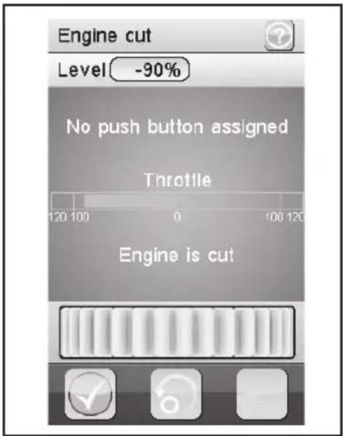
Picture 25
p) Boat mode
This feature allows you to deactivate the brake function, such as when a ship model to be controlled.
Select the parameter to activate or deactivate the braking function.

Picture 26
q) Brake mixing
This feature allows you to control the brakes via two or three independent servos. Channels 3 (CH3), or 4 (CH4) can be used as the slave channels for throttle/brake servo, whereby only the brake function has an influence on the slave channels. After activating one of the two channels, can be adjusted for this channel the ABS and the exponential function of the individually throttle/brake servo.
Select therefor the parameter to change. Move the controller to the right or left to adjust the value according to your wishes. Tap the button "back" in order to save the changes and return to the menu.
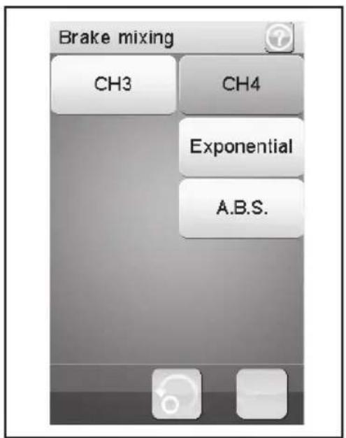
Picture 27
r) Mixes
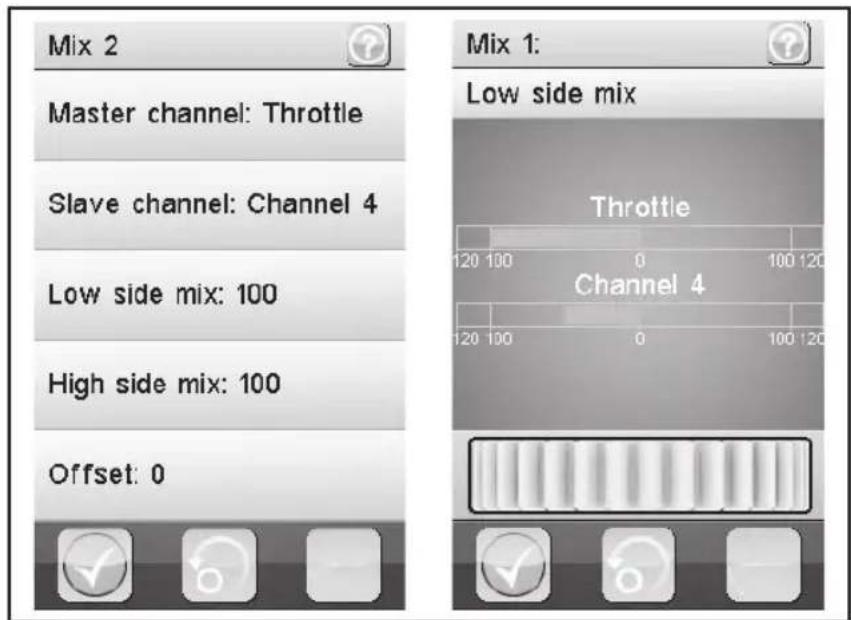
This feature allows you to simultaneously control two servos. The electronic portion of the main channel (master) is hereby mixed on a further channel (slave). You can adjust the direction individually. You can mix between all four channels.
Select a parameter to be mixed. Select the button "activate / deactivate". Move the controller to the right or left to adjust the value according to your wishes. Tap the button "back" in order to save the changes and return to the menu. Tap the button "activate / deactivate" to deactivate the set value.
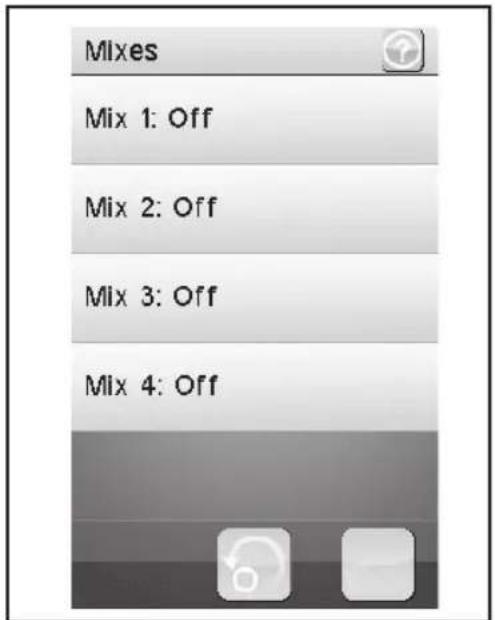
Picture 28
Picture 29
„Master channel“:
Here the master channel is selected.
„Slave channel“:
Here the slave channel is selected.
„Low side mix“:
Here the influence of the left master channel is mixed on the slave channel. A value of 50% shares of the impact on both channels.
„High side mix“:
Here the influence of the right master channel is mixed on the slave channel. A value of 50% shares of the impact on both channels.
„Offset“:
Here is an offset value is added to the slave channel. A negative value shifts the slave channel to its smallest point.
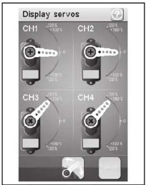
s) Display servos
This feature shows you in real time the position of all four servo arms. Using the "Test" button to investigating whether the mechanism in the model is working properly. Therefore the servo arms moved slowly between its end points back and forth.
Picture 30
t) Race timer
This feature allows the measurement of time in four different modes. Tap on the "Mode" to switch between the four different modes. The following modes are at your disposal:
„Up timer“:
This mode starts the timer and terminated them after touching the "Stop" button.
Tap the "Start" button to start the timer. Then tap the "Stop" button to stop the timer. To set the counter back to "0", tap the "Reset" button.
„Down timer“:
This mode allows you to individually set a countdown time.
Move the controller to the left or right to set a specific time. The adjustable time intervals can be adjusted by one minute.
Tap the "Start" button to start the timer. Then tap the "Stop" button to stop the timer. To set the counter back to "0", tap the "Reset" button.

Picture 31

The timing continues even when the set timing is counted. In this case, the product will automatically switch to the mode "up timer".
„Lap timer“:
This mode allows you to save a certain lap time.
Tap the "Start" button to start the timer. Then tap the button "Lap" to save a lap time. To stop the timer, tap the "Reset" button.

After each activation of the key "Lap" the current lap time is displayed for about 3 seconds on the LCD display and then saved. Meanwhile, the timer runs normally.
„Lap memory“:
This mode displays all stored lap times. You can store up to 100 laps.
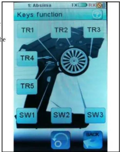
u) Key function
This feature allows you to assign functions for the various trim and switch keys.
Tap one of the trim or switch buttons to give such a specific function. This will open a menu, where you can select the available functions. Tap the button "back" in order to save the changes and return to the menu.
Picture 32
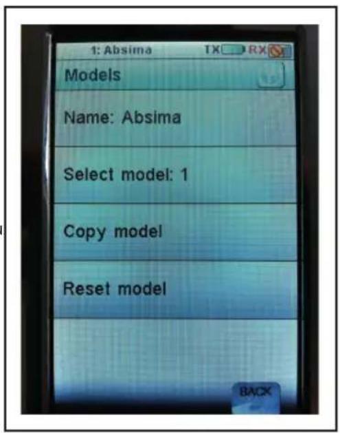
v) Models
This feature allows you to save from 20 model-specific profiles.
„Name“:
Enter the name of the profile. Tap the button "back" in order to save the changes and return to the menu.
„Select model“:
Choose from the list the desired profile. Tap the button "back" in order to activate the selected profile and to get back into the menu
„Copy model“:
Select a profile that you want to copy. Then select a profile that will be overwriting with the new data. Tap the button "back" in order to save the changes and return to the menu.
Picture 33

The selected profile is replaced by the copied profile. All previous settings will be deleted irrevocably.
„Reset model“:
Select a profile to be deleted. Confirm that you really want to delete the profile. Tap the button "back" in order to save the changes and return to the menu.

From the selected profile only the individual settings are deleted, there is the memory for the profile.
w) RX setup
This feature allows you to program the receiver. The following setting options are at your disposal:
„Bind with a receiver“:
Select this when the radio control will be connected to a receiver again.
This feature displays the following information of the receiver battery:
„External sensor“:
Activate this feature if you use an external sensor. This is especially useful if the receiver is powered available via an electronic speed controller with power. Connect therefor the sensor directly to the main battery.
„Low voltage“:
Here you set the minimum voltage stand for a nearly dead battery „Alarm voltage“:

Picture 34
Set here, when the product is to issue an audible alarm when a certain voltage is reached.
„High voltage“:
Here you set the maximum voltage stand for a fully charged battery.
Select therefor the parameter to change. Move the controller to the right or left to adjust the value according to your wishes. Tap the button "back" in order to save the changes and return to the menu.
„Failsafe“:
This feature allows you to program the servo position, which can be adjusted automatically in case of loss the signal from the transmitter. If the setting to "Off" position, the servos remain with signal loss in their last position.
To change the values of the individual servo positions:
Tap the button "activate / deactivate". Move the controller to the right or left to adjust the value according to your wishes. Tap the button "back" in order to save the changes and return to the menu.
Tap the button "activate / deactivate". Pull the throttle/brake trigger forward or backward and hold the desired position.
Tap the button "back" in order to save the changes and return to the menu.
„Throttle“ deactivate:
Select the function "throttle". Tap the button "activate / deactivate" to deactivate the set value.
„Display sensors“:
his feature displays all the information about all connected sensors.
„Choose sensors“:
This function displays information from up to four sensors on the main screen. Tap the parameters and select the desired sensor.
„Speed and distance“:
This feature allows you to program an tachometer connected to the receiver and a displacement measuring device.
Tap on the "Speed sensor" to select a tachometer. "None" means that no one has been selected.
Tap the "Set rotation length" to the circumference of the tire, where the tachometer is connected to cease.
Tap on "Reset odometer 1" or "reset odometer 2" to the virtual odometer again set to "0".
„Servo setup“:
This feature allows you to connect the servo system to an external serial interface. This serves as a channel for the servos. Tap the desired parameters to assign them an external serial interface.
„Servos frequency“:
This feature allows you to adjust the servo frequency. Therefor tap on the desired frequency.
x) System
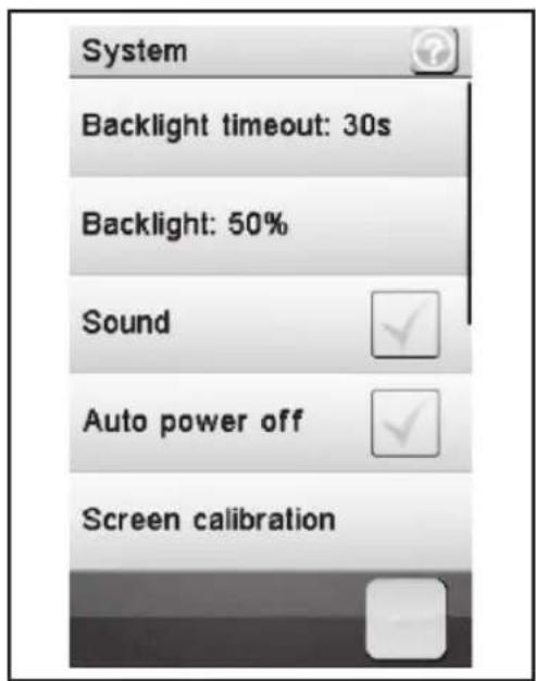
This menu allows different settings for your product.
„Backlight timeout“:
You can set the duration of the backlight of the LCD when it is not touched.
„Backlight“:
This adjusts the brightness of the backlight for the LCD display. A higher value makes for better recognition on the LCD screen, and also for a rapid discharge of the battery.
„Sound“:
Here you can activate or deactivate the speaker or the product.

If you deactivate the speaker, the product will give no warning signals, if the battery voltage is to low.
Picture 35
„Auto power off“:
If the product is not about five minutes in use, an acoustic signal sounds. After another five minutes, the product will shut down automatically. Put a check mark here to activate this feature.
„Screen calibrate“:
You can calibrate the screen display on the LCD screen.
„USB function“:
"ABS-iT 4 emulator" means that the product is connected to a PC and can be operated on this.
„Language“:
Here you can change the menu language of the product. The options are english, french and german
„Firmware update“:
You can arrange a firmware update. Therefore connect the product to a PC available via a Micro USB cable. During the firmware update never remove the battery or the Micro USB cable. The product will lose its functionality and can be rendered unusable.
„Factory reset“:
Here you can put the product back to the factory settings. All previous settings will be deleted.
„About ABS-iT4“:
This shows you the product to the latest firmware version.
16. Service and support
Externally, the remote control can be cleaned with a soft, dry cloth or brush. Do not use abrasive cleaners or chemical solvents, as the surface of the housing could be damaged.
17. Disposal
a) General
Later in the guide, the numbers in the text always on the adjacent image or the images within the section. Cross-references to other pictures are given with the corresponding image number.
b) Batteries
The user is required (Battery Ordinance) to restitution used batteries and accumulators; disposal available via the consumer waste is prohibited!

Contaminated batteries / accumulators are with adjacent symbols, which indicate that it is prohibited to dispose of household waste. The designations for the respective heavy metals are: Cd = cadmium, Hg = mercury, Pb = lead (name on battery / battery as shown in the left waste container symbols).

Their used batteries / accumulators can free vote in the community collection or where batteries / accumulators are sold.
You must comply with the legal obligations and make your contribution to environmental protection.
18. Elimination of errors
Although this remote control system was built using state of the art, it can still cause a malfunction or fault. For this reason, we want to show you how any disturbances can eliminate.
| Problem Corrective | |
| Radio control has no function • Check the batteries.• Check the polarity of the batteries.• Checking function switch. | |
| Servos have no function | • Check the receiver batteries.• Check the switch cable.• Check the BEC.function of the speed controller.• Check the polarity of the servo plugs.• Check the binding function. |
| The servos shiver | • Check the batteries from the transmitter and the receiver.• Any moisture in the receiver gently dry with a heat gun. |
| A servo buzzing | • Check the batteries from the receiver.• Check the steering linkage.• Servo operated for test purposes without servo arm. |
| The radio has only a short range | • Check the batteries from transmitter and the receiver.• Check receiver antenna if is defective.• Receiving antenna in the model for testing different embarrassed. |
| The transmitter turns off immediately even after a short time | • Check the batteries of the transmitter. |
19. Technical specifications
a) Radio
Frequency range: 2,40 - 2,48 GHz FHSS
Bandwidth: 500 KHz
Channels: 4
Power supply:....4,8V - 6V
Measurements (L x H x W): 170 x 206 x 130 mm
Weight: ca. 380 g
Range: >200m
Low battery warning: < 4,5V
b) Receiver
Frequency range: 2,40 - 2,48 GHz FHSS
Channels: 4
Power supply: 4,0V - 6,5V
20. Declaration of conformity (DOC)
The manufacturer hereby declares that this product complies with the essential requirements and other relevant provisions of directive 1999/5/EC.
The declaration of conformity for this product can be found at www.absima.com.
Imprint
This manual is published by the company Absima GmbH, Gibitzenhofstr. 127A, D-90433 Nuremberg (www.absima.com). All rights reserved including translation. Reproduction by any method, for example Photocopying, microfilming or storage in electronic data processing systems, need to the written permission of the publisher. Reproduction in whole or in part is illegal.
This manual suit by the technical status at printing. Changes in technology and equipment are reserved.
© Copyright 2013 by Absima GmbH.



- ABSIMA
- CR4T
- Index
- Page
- Introduction
- For technical questions, contact:
- Correct use
- Product description
- Scope of delivery
- Symbols explanation
- Safety instructions
- a) General
- b) Operation
- Battery details
- Charge batteries
- Please note:
- Radio controls
- Commissioning of the radio
- a) Insert the battery
- b) Turn on the radio control
- c) Test and setting the digital trim
- Center position of the steering function
- Center position of the driving function
- Commissioning of the receiver
- a) Receiver connection
- b) Install the receiver
- c) Install the servo
- d) Binding function
- Install telemetry module
- a) Install a speed telemetry module
- b) Install a voltage telemetry module
- c) Install a temperature telemetry module
- Testing the steering-, drive-, and shift function
- a) Test the steering function
- b) Test the drive function
- Programming the radio control
- a) Programming the radio control
- b) Icon explanation
- c) Handling the LC-Touchscreen-Display
- Adjustments in the main menu
- a) Adjustments main menu
- b) Reverse
- Set the value for the steering servo (CH1)
- Set the value for the throttle servo (CH2)
- Set the value for add-on servos (CH3 and CH4)
- e) Steering exponential
- f) Steering speed
- g) Steering mix
- h) Throttle neutral
- i) Throttle exponential
- j) Throttle curve
- „Brake return“:
- „Delay“:
- „Cycle length“:
- „Trigger point“:
- „Duty cycle“:
- „Steering mix“:
- I) Throttle speed
- m) Throttle middle position
- n) Throttle idle up
- o) Engine cut
- p) Boat mode
- q) Brake mixing
- r) Mixes
- s) Display servos
- t) Race timer
- „Lap timer“:
- „Lap memory“:
- u) Key function
- v) Models
- w) RX setup
- „Failsafe“:
- x) System
- Service and support
- Disposal
- b) Batteries
- Elimination of errors
- Technical specifications
- a) Radio
- b) Receiver
- Declaration of conformity (DOC)
- Imprint
Brand : Absima
Model : CR4T
Category : Remote control