
CR7P - Remote control Absima - Free user manual and instructions
Find the device manual for free CR7P Absima in PDF.
| Product Type | Remote control (transmitter) with receiver for RC models |
| Brand | Absima |
| Model | CR7P |
| Radio protocol | ANT 2.4 GHz (Enhanced Automatic Frequency Hopping Digital System) |
| Number of channels | 7 (CH1 to CH7) |
| Transmitter power supply | 4 AA batteries or LiPo 2S 7.4V battery (JST connector) |
| Receiver power supply | 4.8–6.0 V (via ESC or battery) |
| Display | LCD screen with menus |
| Estimated range | Up to 200 m (depending on conditions) |
| Main functions | Channel reversal (REV), end point adjustment (EPA), sub-trim (SUB TR), dual rate (D/R), curve (CURVE), beginner mode, mixing (MIX), timer, switch assignment, failsafe, range test, sensor, ESC settings, i-BUS, 20 model management |
| Receiver type | R7FS, external antenna, PWM/PPM/i-BUS/S.BUS outputs |
| Calibration | Yes, via the ADJUSTING menu (wheel, trigger, VR2) |
| Firmware update | Yes, via PC (USB cable) from www.absima.com |
| Transmitter dimensions (approx.) | Approximately 200 × 130 × 80 mm |
| Transmitter weight (approx., without batteries) | Approximately 350 g |
| Safety | Configurable failsafe, range test recommended before each use, power off: receiver first |
| Maintenance and cleaning | Store in a cool, dry place, do not expose to moisture, clean with a dry cloth |
| Spare parts and repairability | R7FS receiver available separately, standard batteries, Absima after-sales service |
| Warranty | Manufacturer warranty on material and functional defects (Absima GmbH conditions) |
Frequently Asked Questions - CR7P Absima
User questions about CR7P Absima
0 question about this device. Answer the ones you know or ask your own.
Ask a new question about this device
Download the instructions for your Remote control in PDF format for free! Find your manual CR7P - Absima and take your electronic device back in hand. On this page are published all the documents necessary for the use of your device. CR7P by Absima.
USER MANUAL CR7P Absima
ABSIMA
Achtung • Not following these instructions may lead to minor injuries.
[1] CH1/P(PWM/PPM)
[2]-[5] CH2-CH5
6.4 Einstellungen – D/R (Dual Rate):
Curve function is used to set the output data curve adjustment of the direction channel channel 1, throttle channel channel 2 upper, and brake channel 2 lower channel. The range is -100 to +100. It can change the output sensitivity of each channel. When the data is bigger, the sensitivity of the middle position is bigger and the two end positions are smaller. It is vice versa when the data is smaller.
Function settings:
- In the SET menu, select the CURVE function and press the OK key.
- Select the channel to be adjusted by pressing the UP/DOWN key. Press the OK key to enter the edit state. Select the EXP by pressing the UP/DOWN key and press the OK key. Then press UP/DOWN key to adjust the data. After adjustment, press the return key. If you need to enable this function, select the application item by pressing the UP/DOWN key, and press the OK key to enter the edit state. Press UP/DOWN key to switch on. Then press the return key.
- Test the function to confirm that the adjusted channel output operates normally as expected.
6.6 Settings-Smart Vehicle Control (SVC):
6.27 TX UPDATE (Firmware-Update):
6.30 ABOUT (Version)
This chapter contains the specifications of CR7P transmitter and R7FS receiver.
8.1 Transmitter Specification CR7P
| Model Type Cars, Boats | |
| Channels 7 | |
| RF Frequency 2.4GHz ISM | |
| 2.4G Protocol ANT | |
| Maximum Power <20dBm | (e.i.r.p.) (EU) |
| Reception Sensitivity ≤-99dBm | |
| Channel Resolution 1024 | |
| Low Voltage Warning YES | |
| Input power 4-9V/DC | |
| Battery 1.5AA*4/2S Lipo | (JST) |
| Data Output Type-C Interface | |
| Charging Interface NO | |
| Antenna Type | Built-in single coaxial cable antenna |
| Display Mode 128*64 LCD | (Black and white dot matrix screen) |
| Online Update Absima Assistant Update | |
| Distance ≥300m | (Ground) |
| Working Current | About 110mA/6V |
| Temperature Range | -10°C ~+60°C |
| Humidity Range | 20-90% |
| Size | 136.4*111.8*197.5mm |
| Weight | 305g |
| Certification | CE, FCC ID: N4ZG7Poo |
| Channels 7 | |
| RF Frequency 2.4GHz ISM | |
| 2.4G Protocol ANT | |
| Reception sensitivity ≤-99dBm | |
| Maximum Power | < 20dBm(e.i.r.p.) (EU) |
| Input power 3.5-9V/DC | |
| Distance ≥300m | (Ground) |
| Temperature Range -10 | °C ~+60°C |
| Humidity Range 20-90% | |
| Online Update Absima Assistant Update | |
| Antenna Type External single antenna | |
| Weight 8g | |
| Size 35*23.3*13.3mm | |
| Certification CE, FCC ID | :2A2UNR7Poo |
9. Lieferumfang
CR7P Sender *1
R7FS Empfänger *1
Thank you for purchasing our products.
Read the manual carefully to ensure your personal safety as well as the safety of your equipment.
If you encounter any problems during using, please refer to this manual first. If the problem is still not resolved, please contact the local dealer directly or contact the customer service staff via the website below:
http://www.absima.com

Contents
1. Safety....1
1.1 Safety Symbols ....1
1.2 Safety Guide....1
2. Product Introduction....2
2.1 Transmitter Overview ...... 2
2.2 Receiver Overview ....3
2.2.1 Status LED....3
2.2.2 Interface....3
2.3Antenna .... 3
3. Preparation ....4
3.1 Installing Transmitter Battery....4
3.2 Installing Receiver and Servo....4
4. Operation guide....5
4.1 Power-on....5
4.2 Bind....5
4.3 Setting Transmitter LED and Audio....5
4.4 Calibration....6
4.5 Restoring Factory Settings....6
4.6 Power-off....6
5. System Interface....7
6. Function Menu....8
6.1 Settings-Channel Reverse 9
6.2 Settings-Servo Travel....9
6.3 Settings-Neutral Trim....10
6.4 Settings-Dual Rate....10
6.5 Settings-Curve....11
6.6Settings-Smart Vehicle Control (SVC)....11
6.7 Settings-Beginner Mode....11
6.8 Auxiliary Channels-CH3 to CH7....12
6.9 Mixes 12
6.10 Mixes-Steering Mixes....12
6.11 Mixies-Programming Mixes....13
6.12 Timer....13
6.13 Timer-Timer....13
6.14 Timer-Lap List....13
6.15 Switch Assignment....14
6.16 Receiver Settings....14
6.17 Receiver Settings-Failsafe....14
6.18 Receiver Settings-Bind Settings....15
6.19 Receiver Settings-Range Test....16
6.20 Receiver Settings-Sensor....16
6.21 Receiver Settings-ESC Settings....16
6.22 Receiver Settings-i-BUS Settings ....17
6.23 Model 17
6.24 System Settings....18
6.25 System Settings-System Settings....18
6.26 System Settings-Stick Calibration....19
6.27 System Settings-Firmware Update....19
6.28 System Settings-Factory Reset....20
6.29 System Settings-Help Center....20
6.30 System Settings-About....20
- R7FS Function Instructions....21
7.1 Attentions ......21
7.2 Binding....21
7.3 Firmware update....21
7.4 Failsafe....22
8. Product Specifications....23
8.1 Transmitter Specification CR7P 23
8.2 Receiver Specification R7FS 24
9. Packing List....25
10. Certification....26
10.1 DoC Declaration ....26
10.2 CE Warning 26
10.3 Appendix 1 FCC Statement ......26
11. Environmentally friendly disposal....27
1. Safety
1.1 Safety Symbols
Pay close attention to the following symbols and their meanings. Failure to follow these warnings could cause damage, injury or death.

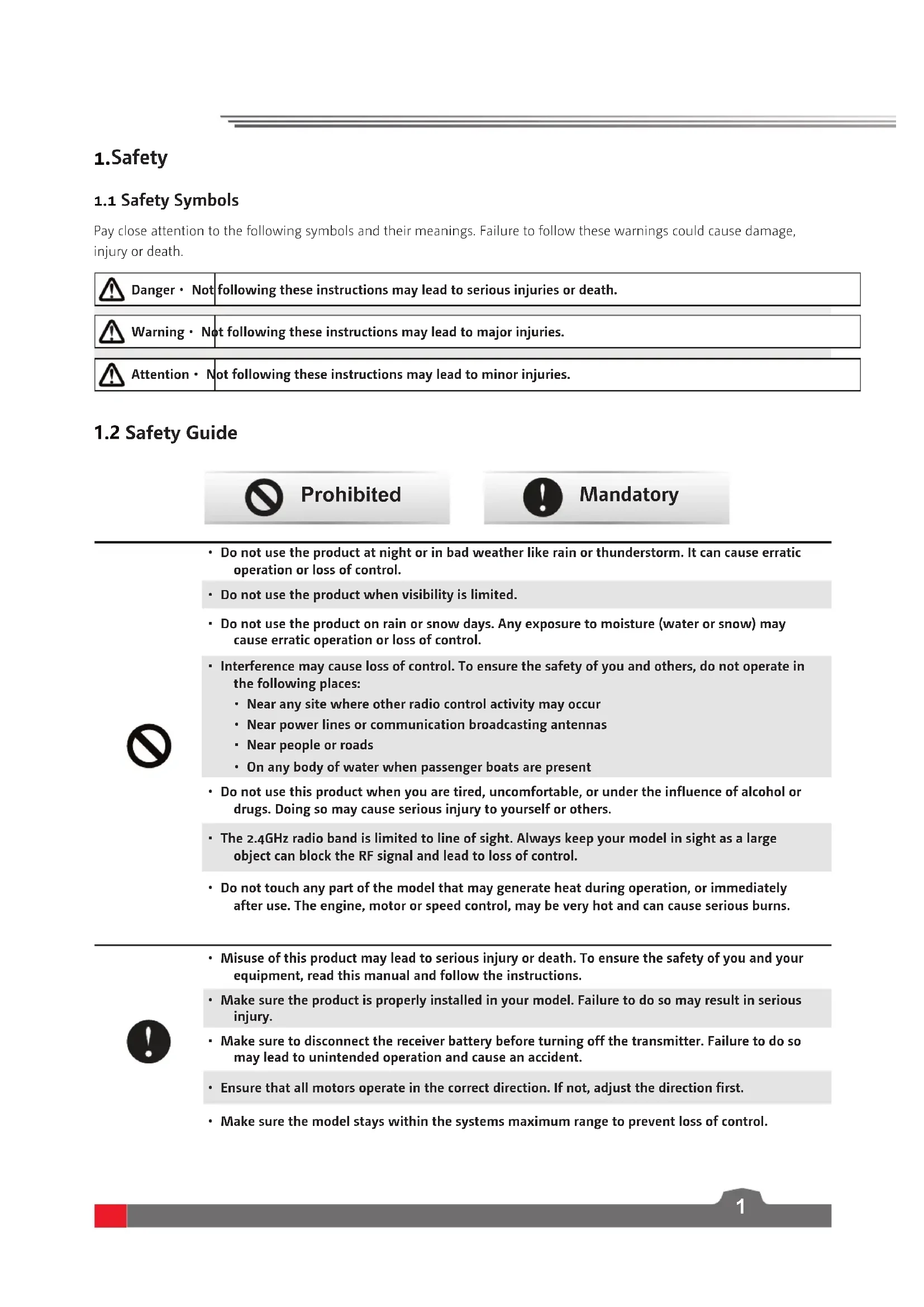
Danger • Not following these instructions may lead to serious injuries or death.

Warning • Not following these instructions may lead to major injuries.

Attention • Not following these instructions may lead to minor injuries.
1.2 Safety Guide

Prohibited

Mandatory

- Do not use the product at night or in bad weather like rain or thunderstorm. It can cause erratic operation or loss of control.
- Do not use the product when visibility is limited.
- Do not use the product on rain or snow days. Any exposure to moisture (water or snow) may cause erratic operation or loss of control.
- Interference may cause loss of control. To ensure the safety of you and others, do not operate in the following places:
• Near any site where other radio control activity may occur
- Near power lines or communication broadcasting antennas
- Near people or roads
- On any body of water when passenger boats are present
- Do not use this product when you are tired, uncomfortable, or under the influence of alcohol or drugs. Doing so may cause serious injury to yourself or others.
- The 2.4GHz radio band is limited to line of sight. Always keep your model in sight as a large object can block the RF signal and lead to loss of control.
- Do not touch any part of the model that may generate heat during operation, or immediately after use. The engine, motor or speed control, may be very hot and can cause serious burns.

- Misuse of this product may lead to serious injury or death. To ensure the safety of you and your equipment, read this manual and follow the instructions.
- Make sure the product is properly installed in your model. Failure to do so may result in serious injury.
- Make sure to disconnect the receiver battery before turning off the transmitter. Failure to do so may lead to unintended operation and cause an accident.
- Ensure that all motors operate in the correct direction. If not, adjust the direction first.
- Make sure the model stays within the systems maximum range to prevent loss of control.
2.Product Introduction
This product uses the 2.4 GHz New ANT(Ant protocol) enhanced automatic frequency hopping digital system, consisting of CR7P transmitter and R7FS receiver. It has an output of 7 channels, compatible with model cars, boats, etc.
2.1 Transmitter Overview
![VR1-Knob SW1-Key [2] Display [1] [4] [5] CH1: Traverding handwheel [7] LED [6] Five-way switch, and keys for menu navigation operations Upward (UP) Downward (DOWN) Right (ENTER) Left (BACK) Middle (OK) [10] SW3: Three-position toggle switch TR_X: Left and right, and trim of preset direction TR_Y: Fr…](/content/2026/04/626078/images/8a71e0e545ee70999e427d9f26c8e7cb4e63b07d2d2db72d7659a712485a4cfd.jpg)
2.2 Receiver Overview
![[8][9][10] [7] [6] [5] [4] [3] [2] [1] [11] [12] [13][14]](/content/2026/04/626078/images/1aaeb0faa7016b6b5bf2ad960984cfdeeece6afe5bb7ead19c1237b2fee700a6.jpg)
![[15] [16] [17]](/content/2026/04/626078/images/d7a71bd943cf69443c17f4b67323b9589cc798aeed8b5ceaeb3348b8857a0885.jpg)
[1] CH1/P(PWM/PPM)
[2]-[5] CH2-CH5
[6] BIND interface
[7] BVD/VCC(Battery voltage detection/Power supply interface)
[8] CH7
[9] SERVO
[10] LED
[11] Antenna
[12] BIND button
[13] SENS interface
[14] CH6
[15] Signal pin
[16] + (Power anode)
[17] - (Power cathode)
2.2.1 Status LED
The status LED indicates the power supply state of the receiver and its working state.
Off: The receiver is not powered on.
Light on in red: The receiver is connected to the power supply. It works normally.
Fast flashing: The receiver is in the bind mode.
Slow flashing: The LED flashes slowly when the receiver is powered off, unbound, or no signal.
2.2.2 Interface
All the interfaces are 2.54 mm standard pins for connecting the receiver to each terminal part of the model. Please follow the direction according to the label see the label direction on the side of the receiver.
2.3 Antenna
It should be noted that this is a transmitter with a built-in antenna. Please use the transmitter correctly.
| Caution | It is strictly prohibited to hold the antenna of the transmitter and the antenna of the receiver in operations. Otherwise, the quality and strength of the radio transmission signal will be greatly reduced, resulting in the failure and out of control of the model. |
| Note | To ensure the signal quality, the transmitter and receiver antennas should be kept vertical to the ground as much as possible. In operations, please adjust the transmitter angle. Make the antenna towards the direction of the model receiver. Keep the receiver antenna extending out of the model and perpendicular to the ground. |
| Note | Do not pull the antenna of the receiver. Do not tie the antenna and the servo cable together. Do not put the antenna close to the metal materials, because this will affect the signal strength of the receiver. |
3. Preparation
Prior to operations, please install the battery and connect devices according to the sequence and guide as described in this chapter.
3.1 Installing Transmitter Battery
| Danger | Only use specified battery (4 x AA batteries). |
| Danger | Do not open, disassemble, or attempt to repair the battery. |
| Danger | Do not crush/puncture the battery, or short the external contacts. |
| Danger | Do not expose to excessive heat or liquids |
| Danger | Do not drop the battery or expose to strong shocks or vibrations. |
| Danger | Always store the battery in a cool, dry place. |
| Danger | Do not use the battery if damaged |
Battery type: AA batteries or 2S lithium batteries JST interface inside the battery compartment.
Please follow the steps below to install the transmitter batteries:
- Open the battery compartment cover.
- Put 4 AA batteries with sufficient electricity into the battery compartment. Ensure that the metal terminals on the batteries contact the metal terminals inside the battery compartment. You should choose the proper size of 2S 7.4V lithium battery to access the JST interface. Connect them correctly.
- Cover the battery compartment.
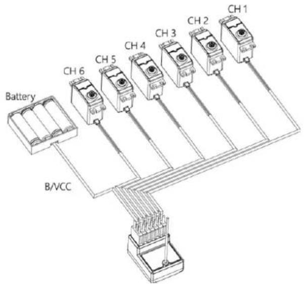
3.2 Installing Receiver and Servo
Install the receiver and servo in the following methods:
4. Operation guide
After the preparation is completed, you can start to use the product according to the guide in this chapter.
4.1 Power-on
Power on the product according to the following steps:
- Check the system status to make sure the battery is fully charged and properly installed.
- Turn the switch to the [On] position. The screen will light up.
- Power on the receiver.

Warning
At this point, the system starts. Please operate carefully. Otherwise, it may cause damage to the product or injury to people.

Warning •
For your safety, please turn the transmitter switch and throttle to the safe position.
4.2 Bind
The ex-factory bind settings of the transmitter and receiver are completed successfully.
If you need to replace the transmitter or receiver with another one, please follow the steps below for binding:
- Connect the power cable to the VCC/BVD interface on the receiver. At this time, the receiver indicator flashes slowly;
- Press and hold the BIND key on the receiver for more than 3 seconds or press and hold the BIND key on the receiver for power-on.
- Power on the transmitter and set the receiver. In the BIND SET, select the BIND: START. At this time, the system is in bind mode.
- After the bind is successful, the receiver LED is always on, and the transmitter automatically exits the bind state;
- After the bind is completed, you can use it normally.
Position of BIND KEY

- The procedure is applicable to the bind between only CR7P transmitter and R7FS receiver. The bind methods vary with receivers. For details about the operations, you can visit the Absima official website to obtain the receiver manual or other related information.
- Since the product is constantly updated, please visit the ABSIMA official website to obtain the latest transmitter and receiver compatibility list.
This product system is compatible with most of our ANT Protocol receiver models. The details are as follows:
RF standard: 2.4 GHz Ant protocol
Receiver model: R7FS
4.3 Setting Transmitter LED and Audio
This LED is a monochromatic light. You can set the ON and OFF state. You can enable or disable the audio for the system operations and alarms. For system operations and alarms, you can enable/disable the audio separately or collectively. In addition, you can set the audio volume separately.
Please follow the steps below to perform the settings:
- Start the transmitter and enter the SYSTEM menu. In the SYSTEM settings, set the LED, SOUND, and VOLUME.
- After the settings are completed, return back.
4.4 Calibration
The calibration is required in case of data offset of the transmitter due to physical wear in long-term operations. At this time, we need to calibrate the output data and neutral angle of the traversing handwheel, throttle trigger, and VR2.
The transmitter has been calibrated at the factory. If you need to recalibrate it, please follow the steps below: Please follow the steps below to perform the settings:
- Power on the transmitter, enter the system menu, and select the stick calibration function. Follow the prompts to press the Start key for calibration.
- Swing the handwheel and trigger to the maximum and minimum travel in each direction respectively and then release them. Toggle the VR2 left and right repeatedly to the maximum extent for two or three times. Finally, toggle the VR2 back to the middle position.
- Press the return key to exit the calibration interface. The calibration is complete. If the pop-up window indicates that the calibration has failed, it means that the control to be calibrated has not reached the maximum and minimum travel, or VRz has not been toggled to the middle position. The re-calibration is required.
4.5 Restoring Factory Settings
When you want to clear the data in the transmitter, you can restore all data in the transmitter to default values. That is, all model data and settings are restored to the default state.
Please follow the steps below to restore factory settings:
- Power on the transmitter, enter the system menu, and select the factory reset function. Follow the prompts to press the OK button to start the reset.
- After the successful reset, the system automatically returns and stays in the system menu interface. It indicates that the system has been restored to the factory settings.
4.6 Power-off
Please follow the steps below to power off the system:
- Power off the receiver.
- Turn the switch to the [OFF] position to turn off the transmitter.

Caution
- When you shut down the system, make sure to power off the receiver, and then the transmitter. Otherwise, the model may be damaged and people may be injured.
5. System Interface
Main system interface
Enter the main system interface after power-on.
NOT SET FAIL SAFE NEED TO STE?
YES
NO
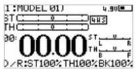
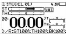
| [1] Model name and number [6] Signal and strength | |||
| [2] Steering channel(ST) output display | [7] | Transmitter voltage and display | |
| [3] Throttle channel(TH) output display [8] Direction | trim display | ||
| [4] Timer [9] Throttle trim display | |||
| [5] DR output display | |||
Sub-page 1
After power-on, enter the main system interface and press the UP key. Press the return key to return to the main system interface.

Sub-page 2
After power-on, enter the main system interface and press the DOWN key. Press the return key to return to the main system interface.
6. Function Menu
Function description:
In this transmitter, we have classified the functions and made a new layout. There are 8 categories in icons in total. That is: Setup(SET), Auxiliary Channel(AUX.CH), MIXES, TIMER, Switch Assignment(SW ASSIGN), Receiver Settings(RX SET), MODEL, System Setup(SYSTEM SET). After the classification, it will become more convenient and easy to set up the model.


SET

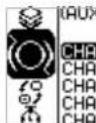
AUX.CH


TIMER


SW ASSIGN


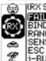
RX SET

Function operations:
In the main interface, press the OK key to enter the function menu. Select the function category by pressing the UP/DOWN key. Press the OK key to enter the corresponding next-level menu.
6.1 Settings-Channel Reverse:
Function: Perform the reverse processing of the output data of one channel or more channels. This function is used in debugging the model.
Application: When the model is designed, there may be no way to determine the unified standard. When we assemble and debug a model, we find that the operation model is reversed to our requirement. For example, the model moves left when we want it to move right. At this time, the transmitter signal output needs to be adjusted. The channel reverse function is used to adjust the action direction of each servo or motor and output signals.
Function settings:
- In the SET menu, select the REV(channel reverse) function and press the OK key to enter
- Select the channel you need to adjust by the pressing UP/DOWN key. Press the OK key to enter the edit state. Then adjust it by the pressing UP/DOWN key. Press return after adjustment.
- Test the function to confirm all the servo or motor action direction is the same as the actually expected direction.

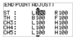
6.2 Settings-Servo Travel:
Function: Adjust the travel amount of the servo output. This function is used in debug. This function can be used to set the travel of the left and right up/down/H/L at both ends of the channel respectively.
When the model is designed, there are changes in the size of the structure and the specification may not be unified. In addition, there may be different sizes of operator's habitual actions. The servo travel function can be used to set the travel amount required for each channel to adjust the
corresponding structure for the best match, to obtain the required operation effect. For example: You want to operate that the turning action is not so large, you can adjust the value of the direction channel at both ends to be smaller. In this way, the turning action should be smaller, with less likely to be tailspin.
Function settings:
- In the SET menu, select the EPA(servo travel) function and press the OK key.
- Select the channel you need to adjust by the pressing UP/DOWN key. Press the OK key to enter the edit state. Then adjust it by the pressing UP/DOWN key. Press return after adjustment.
- Test the function to confirm all the servo or motor action directions are the same as the actual expected travels.
6.3 Settings-Neutral Trim:
Function: Set and adjust the neutral data of each channel.
This function is mainly used for the trim of the model in assembly and debugging. For example, the vehicle is stationary and the transmitter traversing handwheel is in the neutral position; if you find that the wheels deviate from the straight direction, it can be easily corrected through this function. At this time, it is difficult and inconvenient to adjust the model structure.
Note: Before setting this function, make sure that the channel is moving in the correct direction.
Function settings:
- In the SET menu, select the SUB TR(neutral trim) function and press the OK key.
- Select the channel you need to adjust by the pressing UP/DOWN key. Press the OK key to enter the edit state. Then adjust it by the pressing UP/DOWN key. Press return after adjustment.
- Observe and test the function to ensure that the settings work as expected.

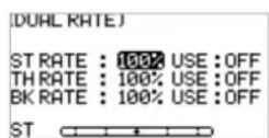
6.4 Settings-Dual Rate:
Dual rate allows you to quickly adjust the output value of certain channels to achieve the best manipulation effect. The rate function can be used to set the direction channel channel 1, throttle channel channel 2 upper, brake channel 2 lower channel, and output data rate. The range is 0-100%. You can also set the switch-on and switch-off. The two control modes can be switched through the application switch setting, see the Key Setting menu.
Function settings:
- In the SET menu, select the D/R(Dual rate) function and press the OK key.
- Select the channel you need to adjust by the pressing UP/DOWN key. Press the OK key to enter the edit state. Then adjust it by the pressing UP/DOWN key. Press return after adjustment. In the adjustment, observe by operating the corresponding channel handwheel and throttle trigger.
- Verify the function to confirm that all channel outputs operate normally as expected.
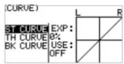
6.5 Settings-Curve:
Curve function is used to set the output data curve adjustment of the direction channel channel 1, throttle channel channel 2 upper, and brake channel 2 lower channel. The range is -100 to +100. It can change the output sensitivity of each channel. When the data is bigger, the sensitivity of the middle position is bigger and the two end positions are smaller. It is vice versa when the data is smaller.
Function settings:
- In the SET menu, select the CURVE function and press the OK key.
- Select the channel to be adjusted by pressing the UP/DOWN key. Press the OK key to enter the edit state. Select the EXP by pressing the UP/DOWN key and press the OK key. Then press UP/DOWN key to adjust the data. After adjustment, press the return key. If you need to enable this function, select the application item by pressing the UP/DOWN key, and press the OK key to enter the edit state. Press UP/DOWN key to switch on. Then press the return key.
- Test the function to confirm that the adjusted channel output operates normally as expected.

6.6 Settings-Smart Vehicle Control (SVC):
The Smart Vehicle Control function is used to set the receiver with the SVC function. The current R7FS does not have the SVC function.

6.7 Settings-Beginner Mode:
The beginner mode function is used to set the output limit of direction channel and throttle channel. After this function is enabled, the channel output is only 50%. In this way, the beginner can easily drive the vehicle under the condition of limiting the speed and turning angle.
Function settings:
- In the SET menu, select the BEGINNER function and press the OK key.
- Select the item you need to adjust by pressing the UP/DOWN key. Press the OK key to enter the edit state. Then adjust it by pressing the UP/DOWN. Press return after adjustment.
- Test the function to confirm that all channel outputs operate normally as expected.

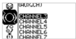
6.8 Auxiliary Channels-CH3 to CH7
For some models with complex functions, we provide up to 7 channels of output, 5 of which are auxiliary channels for the most effective control of multiple functions in different ways. The Auxiliary Channels function is used to set the control settings for CH3 to CH7, assigning targeted controls to the channels for operation.
Function settings:
- In the AUX.CH menu, select CH3 to CH7 and press the OK key.
- Select the item you need to adjust by pressing the UP/DOWN key. Press the OK key to enter the edit state. Then adjust it by pressing the UP/DOWN. Press return after adjustment.
- Test the function to confirm that all channel outputs operate normally as expected.
6.9 Mixes
Mixes is enabled for some models that require two channels to act in conjunction with each other. The Mixing channel function provides 1 steering mixes plus 5 programmable mixes.
Function settings:
In the main interface, press the OK key to enter the function menu. Select the MIXES menu by pressing the UP/DOWN key, and press the OK key to enter the edit state.

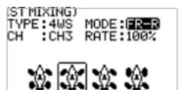
6.10 Mixes - Steering Mixes
This is a special function mixing. The ST MIXING(Steering Mix) provides two types of mixing, that is, TRACK(track-specific) mixer and 4WS mixer.
The 4WS mixer provides 4 different schemes for front and rear wheels to meet the different requirement scenarios for different vehicles.
Function settings:
- In the MIXES menu, select the ST MIXING and press the OK key.
- Select the item you need to adjust by pressing the UP/DOWN key. Press the OK key to enter the edit state. Then adjust it by pressing the UP/DOWN. Press return after adjustment.
- Test the function to confirm that all channel outputs operate normally as expected.

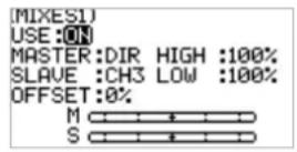
6.11 Mixing-Programming Mixes
The programming mixes function is used to mix the output data of any channel to another channel in a certain rate, to achieve a desired mixing effect.
Function settings:
- In the MIXES menu, select a MIX and press the OK key.
- Select the item you need to adjust by pressing the UP/DOWN key. Press the OK key to enter the edit state. Then adjust it by pressing the UP/DOWN. Press return after adjustment.
- Test the function to confirm that all channel outputs operate normally as expected.
6.12 Timer
Timer menu provides two functions: TIMER and LAP LIST.
Function settings:
In the main interface, press the OK key to enter the function menu. Then select the TIMER menu by pressing the UP/DOWN key. Press the OK key to enter the edit state.
6.13 Timer – Timer
The Timer function is used for timing in races, including counting, countdown, and lap counting. You can also use it to test a tank of fuel or a full battery and confirm the usage time. In the alarm parameter setting, you can set the alarm prompt time when the timer starts. For example, set to 05MooS. This means the alarm will start when the countdown reaches 5 minutes.
Function settings:
- In the TIMER menu, select the TIMER and press the OK key.
- Select the item you need to adjust by pressing the UP/DOWN key. Press the OK key to enter the edit state. Then adjust it by pressing the UP/DOWN. Press return after adjustment.
- Test the function to confirm that all setting outputs operate normally as expected.

6.14 Timer-Lap List
The data display page is available only when you use the lap counting function. You can view the entire duration, the fastest lap time, and the average lap time. Thus, you can easily judge and adjust the operation to finally achieve a good result. The start and stop of the lap time can be set through the Key Setting menu see Key Setting menu for details.

6.15 Key Settings
The key setting function is to assign switches to some functions in order to control the output of the actions needed through the specified switch. According to the types, it includes trim, switch, and knob.
Function settings:
- In the SW ASSIGN(switch assignment) menu, select a item and press the OK key.
- Select the item you need to adjust by pressing the UP/DOWN key. Press the OK key to enter the edit state. Then adjust it by pressing the UP/DOWN. Press return after adjustment.
- Test the function to confirm that all channel outputs operate normally as expected.

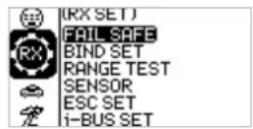
6.16 Receiver Settings
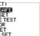
The RX SET(receiver setting) menu provides a number of function setting menus to allow you to set up the receiver system in all aspects. That is, FAILSAFE, BIND SET, RANGE TEST, SENSOR, ESC SET, and I-BUS SET.
Function settings:
In the main interface, press the OK key to enter the function menu. Select the RX SET(receiver setting) menu by pressing the UP/DOWN key. Press the OK key to enter the function setting interface.
6.17 Receiver Settings-Failsafe:
Failsafe is an important safety setting. It can be used to protect the model from loss or reduce the degree of loss when the receiver loses signal without control. In addition, it plays a role in protecting personnel safety.
You can set the data in case of loss of control for all output channels. There are three output states. If the state is not set, the output is low level state. It is mainly for giving you a reminder. The no output state is also an output of a low level, that is, no signal state. If the output is set, there is the corresponding output according to your requirements. The specific mode settings depend on the terminal device and operation requirements. For example, some governors take no signal as the stop signal. If the out-of-control receiver needs to output a low level no signal, the governor will enter the protection. Another example: If it is an engine, we need to output a brake signal to the brake servo if it is out of control, we need to set that there is an output and it is in the brake state.

Function settings:
- In the RX SET(receiver setting) menu, select the FAILSAFE by pressing the UP/DOWN key. Press the OK key to enter the function setting.
- Select the item you need to adjust by pressing the UP/DOWN key. Press the OK key to enter the edit state. Then adjust it by pressing the UP/DOWN. Press return after adjustment.
- Test the function by powering off the transmitter to confirm that all channel outputs operate normally as expected.

6.18 Receiver Settings - Bind Settings:
The transmitter and the receiver have been bound with each other before delivery and can be operated directly. If you want to replace the receiver, you need to bind the new receiver with the transmitter by using the binding function before they can be operated normally.
Four parameters - RF type, receiving type, output mode, response speed - and a BIND key are provided for setting purpose.
RF type: There are two options available, ANT1WAY one-way and ANT2WAY two-way. If you are using a two-way receiver, it is recommended to select ANT2WAY two-way, which may bring you a better experience with more information feedback.
ANT1WAY means a one-way mode. In this mode, only the transmitter gives commands to the receiver; while the receiver outputs and performs commands received from the transmitter. The advantage is that it can ensure simultaneous operation by more users on the same site with less interference.
ANT2WAY means a two-way mode, which enables intercommunication between the transmitter and the receiver to be configured with the corresponding functions, so that the basic information of the model can be provided to the user in real time. For example, if you want to know the battery voltage of the model vehicle, you can enable this option and bind the receiver configured with this function, then you can read the battery voltage value on the transmitter.
Receiver type: Two options are available, namely standard receiver and two-in-one receiver, which can be selected according to the receiver you are using. The option of two-in-one receiver means a receiver configured with a ESC; however, standard receivers are supplied by default. For details, please visit our website to learn more about relevant models.
Output mode: There are four optional output modes (combination of two output modes), i.e., PWM/SBUS, PPM/IBUS, PWM/IBUS, PPM/SBUS four output modes, which can be selected according to actual needs.
Servo frequency: There are three optional output modes, i.e., analog, digital and others, which can be selected according to the type of servo. The digit following each option is used to set the frequency of the servo output.
Note: The frequency of analog servos, digital servos and other servos are 60HZ, 380HZ and 50HZ-400HZ respectively.
Function settings:
- In the BIND SET menu, select the item to be adjusted by pressing the UP/DOWN key and press the OK key for editing. Set the desired value by pressing the UP/DOWN key and press the OK key to confirm the adjustment.
- After the adjustment and setting are completed, select START by pressing the UP/DOWN key and
press the OK key to bind with the receiver. For details, please refer to the chapter for binding operation and the Quick Start Guide.
- After finishing the above step, carry out a test to confirm that all channel outputs are functioning as expected.


6.19 Receiver Settings - Range Test:
As an important function, it is recommended to conduct the range test before each operation to check whether the remote controller is functional or environmental conditions are normal.
Working principle: It is aimed to conduct a narrow-ranged test by actively reducing the power of the transmitter, in order to realize quick inspection of the transmitter system and the environment. There are three parameters (power, signal, RSSI) displayed and indicated on the transmitter interface.
Function settings:
- In the RANGE TEST menu, directly press the SW2 key to conduct the test.
- You should keep the transmitter still during the test, but you can move your model at this time. If there is no problem in the test within a certain range, the device can be used normally.

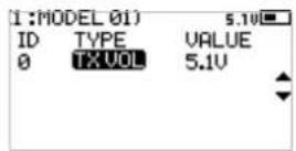
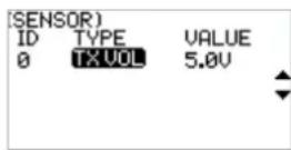
6.20 Receiver Settings - Sensor
As an interesting feature for two-way communication systems, sensors can be used to send back some information you need through the receiver.
Our transmitter can support up to 15 different types of returned data to provide you with the feedback of seven basic parameters, i.e., TX VOL(TX voltage), RX VOL(RX voltage), BVD VOL(BVD voltage), SIGNAL(signal intensity), NOISE, SNR(noise rate) and RSSI. BVD: detect an external power supply. It is recommended to use this function to monitor the battery voltage and give an alarm in case of a failure.
Function settings:
In the SENSOR menu, scroll pages by pressing the UP/DOWN key to check relevant information.
6.21 Receiver Settings - ESC Settings
The ESC SET(ESC Setting) menu is an additional option provided specially for two-in-one ESC, which is used to set the two-in-one governor more precisely to ensure its optimal performance. To enable this setting, you need to switch the receiver type to the two-in-one option in the Receiver settings - Bind Setting menu.
Three parameters, namely operating mode, battery type, and drag braking force can be setup here.
There are two braking modes as follows: the first mode is FOR/BRK/REU that means, the device moves forward when pressing the trigger for acceleration; it is braked when pulling the trigger backward and then reverses when releasing the trigger to the neutral position and then pulling it backward again; and the second mode is forward/reverse that means, the device moves forward when pressing the trigger for acceleration, and it reverses immediately when pulling the trigger backward. These two modes can be set according to actual needs.
Function settings:
- In the ESC SET menu, select the item to be adjusted by pressing the UP/DOWN key and press the OK key for editing. Set the desired value by pressing the UP/DOWN key and press the OK key to confirm the adjustment.
- After that, carry out a test to confirm that all set channel outputs are functioning as expected.

6.22 Receiver Settings -i-BUS Settings
The i-BUS SET(i-BUS setting) function is a unique and powerful serial communication protocol system provided by Absima. It can be output to any channel by setting. For receivers with i-BUS interface and corresponding accessories, see the description of serial bus receivers for details.
Function settings:
- The transmitter and receiver are completed successfully;
- Connect the input cable of the i-BUS receiver to the SERVO port of the receiver;
- Connect the servo to the C1-C4 ports of the i-BUS receiver;
- Turn on the transmitter to enter the i-BUS SET interface, and select the channel to be assigned; if the channel is incorrect, select "CANCEL" to re-set;
Note: If the interface prompts to set the RF type to "ANT TWO WAY" first, set the RF type to ANT TWO WAY first.
-
Press the corresponding button on the i-BUS receiver. After the setting is successful, the system will pop up a pop-up window showing the interface number of the currently selected channel assigned to the i-BUS receiver.
-
Repeat the above steps to set more channels.
Note: If the receiver is overloaded, please supply power separately to prevent the wire from being burnt out due to excessive current.

6.23 Model
The MODEL menu is used for model management. It includes four options: select model, model name, copy model and reset model.
SELECT: The transmitter can save up to 20 sets of model data, and you can call out one set of model data at any time and use it as needed.
NAME: The name of the model you select can be edited and changed.
COPY: If you have a new model that is the same or similar to the model you used before, you can use this function to make a copy for quick setting.
RESET: It literally means that this function will reset all the set values of the model parameters and restore the factory settings.
Function settings:
- In the MODEL menu, select the item to be set by pressing the UP/DOWN key and press the OK key to enter the corresponding function submenu.
- If the SELECT option is selected, you can choose the desired model number by pressing the UP/DOWN key and press the OK key for confirmation. At this time, a dialog box will pop up. Then just select YES by pressing the UP/DOWN key and press the OK key for confirmation.
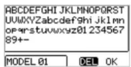
- If the NAME option is selected, you can choose the desired letters or digits by pressing the UP/DOWN key for editing. After the selection is finished, press the OK key to return.
- If the COPY option is selected, you can choose the model to be copied by pressing the UP/DOWN key and press the OK key for confirmation. Then choose the model number for copy by pressing the UP/DOWN key and press the OK key for confirmation. Finally select YES and press the OK key for confirmation.
- If the RESET option is selected, a dialog box will pop up. Just select YES by pressing the UP/DOWN key and press the OK key for confirmation.


6.24 System Settings
The System menu includes six function submenus, i.e., system settings, stick calibration, firmware update, factory reset, help center and about.
Function settings:
In the System menu, select the item to be set by pressing the UP/DOWN key and press the OK key to enter the corresponding function submenu.

6.25 System Settings - System Settings
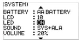
The system setting function is used to set the transmitter system, including setting the language, idle alarm time, battery type, display contrast & brightness, LED light, system sound and volume.
Description of battery type:
AA battery means a widely-used R6 alkaline dry battery. 2S means two lithium-ion cells, which are non-standard specialized battery. Please consult specialists before use to avoid error alarms or dangers of over-discharge or over-heating! No other batteries are recommended.
Function settings:
In the SYSTEM SET menu, select the item to be set by pressing the UP/DOWN key and press the OK key for editing. Set the desired value by pressing the UP/DOWN key and press the OK key to confirm the adjustment.

6.26 System Settings - Stick Calibration
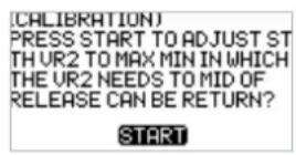
The CALIBRATION(stick calibration) function is used to restore the data of the neutral position and endpoints, which are changed for certain reasons after the transmitter has been used for a long time. The ST, TH and VR2 channels can be recovered by using this function please refer to the chapter for stick calibration.
Function settings:
- In the CALIBRATION menu, turn the steering wheel left and right to the maximum and return it to the neutral position; pull the trigger back and forth and return it to the neutral position; then turn VR2 left and right to the maximum and return it to the neutral position; and finally press the OK key to confirm the calibration.
- Carry out a test to confirm that all channel outputs set after calibration are functioning as expected.


6.27 System Settings - Firmware Update
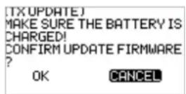
The FW UPDATE(firmware update) function is used for synchronizing the system to the latest version and experiencing better functions and services when the firmware is upgraded by the manufacturer.
Function settings:
Note: This function is only available in the Absima Assistant software provided by Absima.
- In the FW UPDATE menu, a dialog box will pop up. At this time, you can select YES by pressing the UP/DOWN key and press the OK key to start the update session. The current menu will be closed directly once the update session is completed.
- Carry out a test to confirm that the transmitter functions normally after the update.
Note: Always ensure sufficient power supply for the transmitter when using this function.

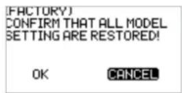
6.28 System Settings - Factory Reset
The FACTORY(factory reset) function is used to restore the entire transmitter system to the factory settings in case a number of parameters are adjusted incorrectly during operation.
Function settings:
- In the FACTORY menu, a dialog box will pop up. At this time, you can select YES by pressing the UP/DOWN key and press the OK key to reset the transmitter. The current menu will be closed automatically once the resetting process is completed.
- Carry out a test to confirm that the transmitter functions normally after it is reset.
Note: When activating this function, all parameters will be reset, including the model data you have saved before. It is important to back up the data first if necessary. For details, please refer to the relevant functions of Absima Assistant.
6.29 System Settings - Help Center
The HELP(Help Center) provides a QR code of the user manual. You can use your mobile phone to scan the QR code to retrieve the information you want to know. It enables you to quickly access the electronic version of the user manual if there is no hard copy in hand. You can also find the company website and official media accounts in this menu which may facilitate interactive communication between Absima and customers in future.

6.30 System Settings - About
The ABOUT function submenu is used to display the system firmware and hardware information which can be referred to for future maintenance purposes.
TYPE :CR7P
FW :1.0.0.19
TIME : 2021-12-29
HW :1.5
RF :1.0
7.R7FS Function Instructions
R7FS based on ANT protocol is a receiver which provides seven channels. It has an external single antenna, can output PWM or PPM/i-BUS/S.BUS signal. It has a compact design. It can be adapted to a variety of model cars or boats.
Note: See [2.3 Receiver Overview] for interface Introduction details.
7.1 Attentions
- Make sure the product is installed and calibrated correctly, failure to do so may result in serious injury.
- Make sure the receiver's battery is disconnected before turning off the transmitter, failure to do so can result out of control.
- Unreasonable setting of the Failsafe may cause accidents.
- Make sure the receiver is mounted away from motors, electronic speed controllers or any device that emits excessive electrical noise.
- Keep the receiver's antenna at least 1cm away from conductive materials such as carbon or metal.
- Do not power on the receiver during the setup process to prevent loss of control.
7.2 Binding
If you need to re-bind the receiver, please refer to [4.2 Bind] for the steps.
Notes :
- Set the transmitter to its binding state first, and then set the receiver to its binding state. If the binding is not completed within 10s, the indicator light of the receiver will enter its slow flashing state.
- If re-binding is successful, all the settings of the car lights will be restored to their default values.
7.3 Firmware update
The firmware of this receiver can be updated through the Absima Assistant (Only version 3.0 or above is supported. The firmware of Absima Assistant is available on the Absima official website).
- This receiver can be updated via the following two ways: After the binding between the transmitter and the receiver (the LED of the receiver is solid on), connect the transmitter to the computer, then open the AbsimaAssistant on the computer to update the firmware.
- Connect the transmitter to the computer. Then put the receiver to enter the forced update mode by referring to the following three ways (The LED of the receiver operates in three-flash-one-off manner repeatedly). Afterwards, open the Absima Assistant on the computer to update the firmware.
- Power on the receiver while pressing and holding the BIND button for more than ten seconds, until the LED of the receiver operates in three-flash-one-off manner repeatedly, then release the BIND button.
- Power on the receiver first, then press and hold the BIND button for more than ten seconds, when the LED of the receiver operates in three-flash-one-off manner repeatedly, then release the BIND button.
- Connect the bind cable to the signal pins of the CH4 and CH6, then power on the receiver
Notes: The method of activating the binding or mandatory updating function may vary according to the type of receiver. For details, please refer to the user manual of the corresponding receiver.
7.4 Failsafe
The failsafe function is used to output the channel value according to the out-of-control protection value set by the user after the receiver loses its signal and is out of control to protect the model and personnel.
It can also be set failsafe for each channel respectively. This receiver supports two failsafe modes: [ON] and [OFF]
[OFF] It is no output for the interface of PWM.
[ON] Outputs the failsafe values set for each channel.
Notes:
- For bus signal types such as PPM/i-BUS/S.BUS, a single or several of these channels are not allowed to be in [No output] mode. The actual signal is held at the last output value when the channel is set to [No output] mode.
- Because the S.BUS signal information contains failsafe flag bits, the failsafe settings of each channel are communicated to subsequent devices by the failsafe flag bits. If the connected devices support the failsafe flag bit analysis, the failsafe values set for each channel are output after out of control.
- For the signal PPM/i-BUS without failsafe flag bits, it supports the setting of the signal to [No output] mode in case of out of control. After setting to [No output] mode, regardless of the setting of the failsafe of each channel, each channel will be in [No output] mode after out of control.
8. Product Specifications
This chapter contains the specifications of CR7P transmitter and R7FS receiver.
8.1 Transmitter Specification CR7P
| Model Type Cars, Boats | |
| Channels 7 | |
| RF Frequency 2.4GHz ISM | |
| 2.4G Protocol ANT | |
| Maximum Power <20dBm | (e.i.r.p.) (EU) |
| Reception Sensitivity ≤-99dBm | |
| Channel Resolution 1024 | |
| Low Voltage Warning YES | |
| Input power 4-9V/DC | |
| Battery 1.5AA*4/2S Lipo | (JST) |
| Data Output Type-C Interface | |
| Charging Interface NO | |
| Antenna Type | Built-in single coaxial cable antenna |
| Display Mode 128*64 LCD | (Black and white dot matrix screen) |
| Online Update Absima Assistant Update | |
| Distance ≥300m | (Ground) |
| Working Current | About 110mA/6V |
| Temperature Range | -10°C ~+60°C |
| Humidity Range | 20-90% |
| Size | 136.4*111.8*197.5mm |
| Weight | 305g |
| Certification | CE, FCC ID:N4ZG7Poo |
8.2 Receiver Specification R7FS
| Channels 7 | |
| RF Frequency 2.4GHz ISM | |
| 2.4G Protocol ANT | |
| Reception sensitivity ≤-99dBm | |
| Maximum Power | < 20dBm (e.i.r.p.) (EU) |
| Input power 3.5-9V/DC | |
| Distance ≥300m | (Ground) |
| Temperature Range -10 | °C ~+60°C |
| Humidity Range 20-90% | |
| Online Update Absima Assistant Update | |
| Antenna Type External single antenna | |
| Weight 8g | |
| Size 35*23.3*13.3mm | |
| Certification CE, FCC ID | :2A2UNR7P00 |
9. Packing List
Transmitter*1 (CR7P)
Receiver*1 (R7FS)
10. Certification
Warranty Terms
By purchasing and using your Absima product, you agree to the warranty terms of Absima GmbH. The warranty applies only to material and/or functional defects already present at the time of purchase of the product.
Excluded from the guarantee:
• Damage caused by incorrect use
- Damage due to neglect of duty of care
- Damage due to improper handling and maintenance errors
- Fluid damages
Please report warranty claims to your dealer.
If it is necessary to return your product, please enclose your proof of purchase and a detailed description of the fault with the shipment. We also need your complete contact details (legible).
The direct sending to the service department of Absima GmbH requires the previous arrangement. This can be done by telephone under +49 911 65084130 or by e-mail to service@absima.com
The shipping costs are borne by the sender. Parcels that are not free of charge or are subject to charges will not be accepted.
Each incoming warranty case is first checked by our service department for admissibility. Complaints that are not covered by the warranty may incur costs for the inspection. Repairs or services that are not covered by the warranty will be charged in advance.
Disclaimer
Since Absima GmbH cannot at any time monitor the observance of the operating instructions as well as the operation and conditions of use of the product, Absima GmbH does not assume any liability for damages, costs, losses resulting from incorrect handling and/or incorrect operation or in any way related thereto. To the extent permitted by law, the obligation to pay damages, for whatever legal reason, will be limited to the invoice value of the Absima product involved in the event. This does not apply as far as we have to assume unlimited liability due to mandatory legal regulations or gross negligence.
Declaration of conformity
The manufacturer hereby declares that the product complies with the essential requirements and other relevant provisions of the EU Directive.
The declaration of conformity can be found at
http://absima.com/index.php/downloads/erklaerungen/
or can be consulted under
Absima GmbH - Gibitzenhofstrasse 127a/RG - 90443 Nuremberg, Germany can be requested.

Disposal

Waste electronic equipment is a raw material and should not be disposed of with household waste. If the product is at the end of its service life, dispose of it at your local collection points in accordance with the applicable legal regulations.
Disposal with household waste or at the expense of the environment is prohibited.
Important! Remove the batteries or rechargeable batteries before disposal. A separate take-back system applies to batteries and rechargeable batteries.
By properly disposing of your old appliances, you make an important contribution to environmental protection.
Absima GmbH
Gibitzenhofstrasse 127 a / RG
90443 Nürberg, Germany
Phone: +49 911 65084130 / Fax: +49 911 65084140
www.absima.com
Technical changes, design and equipment subject to change without notice.

4.2 Affectation....5
64 Réglages-Dual Rate....10
6.5 Réglages-Courbe....11
6.6 Réglages-Smart Vehicle Control (SVC)....11
[1] CH1/P(PWM/PPM)
[2]-[5] CH2-CH5
[6] Interface BIND
[7] BVD/VCC (protection de la tension de la batterie/interface d'alimentation)
[8] CH7
[9] SERVO
[10] LED
[11] Antenne
[12] Bouton BIND
[13] Interface SENS
[14] CH6
6.2 Réglages - EPA (END POINT ADJUSTMENT)
6.4 Réglages - D/R (Dual Rate)
6.26 ADJUSTING (calibrage)
This chapter contains the specifications of CR7P transmitter and R7FS receiver.
| Model Type Cars, Boats | |
| Channels 7 | |
| RF Frequency 2.4GHz ISM | |
| 2.4G Protocol ANT | |
| Maximum Power <20dBm | (e.i.r.p.) (EU) |
| Reception Sensitivity ≤-99dBm | |
| Channel Resolution 1024 | |
| Low Voltage Warning YES | |
| Input power 4-9V/DC | |
| Battery 1.5AA*4/2S Lipo | (JST) |
| Data Output Type-C Interface | |
| Charging Interface NO | |
| Antenna Type | Built-in single coaxial cable antenna |
| Display Mode 128*64 LCD | (Black and white dot matrix screen) |
| Online Update Absima Assistant Update | |
| Distance ≥300m | (Ground) |
| Working Current | About 110mA/6V |
| Temperature Range | -10°C ~+60°C |
| Humidity Range | 20-90% |
| Size | 136.4*111.8*197.5mm |
| Weight | 305g |
| Certification | CE, FCC ID: N4ZG7Poo |
| Channels 7 | |
| RF Frequency 2.4GHz ISM | |
| 2.4G Protocol ANT | |
| Reception sensitivity ≤-99dBm | |
| Maximum Power | < 20dBm(e.i.r.p.) (EU) |
| Input power 3.5-9V/DC | |
| Distance ≥300m | (Ground) |
| Temperature Range -10 | °C ~+60°C |
| Humidity Range 20-90% | |
| Online Update Absima Assistant Update | |
| Antenna Type External single antenna | |
| Weight 8g | |
| Size 35*23.3*13.3mm | |
| Certification CE, FCC ID | :2A2UNR7Poo |
9. contenu de la
Émetteur CR7P *1
Récepteur R7FS *1
batteries et aux batteries rechargeables.
ABSIMA


- ABSIMA
- 6.4 EINSTELLUNGEN – D/R (DUAL RATE)
- FUNCTION SETTINGS
- 6.6 SETTINGS-SMART VEHICLE CONTROL (SVC)
- 6.27 TX UPDATE (FIRMWARE-UPDATE)
- 6.30 ABOUT (VERSION)
- LIEFERUMFANG
- CONTENTS
- SAFETY....1
- PRODUCT INTRODUCTION....2
- PREPARATION ....4
- OPERATION GUIDE....5
- SYSTEM INTERFACE....7
- FUNCTION MENU....8
- SAFETY
- 1.1 SAFETY SYMBOLS
- 1.2 SAFETY GUIDE
- PROHIBITED
- MANDATORY
- 2.PRODUCT INTRODUCTION
- 2.2 RECEIVER OVERVIEW
- 2.2.1 STATUS LED
- 2.2.2 INTERFACE
- 2.3 ANTENNA
- PREPARATION
- 3.1 INSTALLING TRANSMITTER BATTERY
- 3.2 INSTALLING RECEIVER AND SERVO
- OPERATION GUIDE
- 4.1 POWER-ON
- 4.2 BIND
- 4.3 SETTING TRANSMITTER LED AND AUDIO
- 4.4 CALIBRATION
- 4.5 RESTORING FACTORY SETTINGS
- 4.6 POWER-OFF
- SYSTEM INTERFACE
- SUB-PAGE 1
- SUB-PAGE 2
- FUNCTION MENU
- 6.1 SETTINGS-CHANNEL REVERSE
- 6.2 SETTINGS-SERVO TRAVEL
- 6.3 SETTINGS-NEUTRAL TRIM
- 6.4 SETTINGS-DUAL RATE
- 6.5 SETTINGS-CURVE
- 6.7 SETTINGS-BEGINNER MODE
- 6.8 AUXILIARY CHANNELS-CH3 TO CH7
- 6.9 MIXES
- 6.10 MIXES - STEERING MIXES
- 6.11 MIXING-PROGRAMMING MIXES
- 6.12 TIMER
- 6.13 TIMER – TIMER
- 6.14 TIMER-LAP LIST
- 6.15 KEY SETTINGS
- 6.16 RECEIVER SETTINGS
- 6.17 RECEIVER SETTINGS-FAILSAFE
- 6.18 RECEIVER SETTINGS - BIND SETTINGS
- 6.19 RECEIVER SETTINGS - RANGE TEST
- 6.20 RECEIVER SETTINGS - SENSOR
- 6.21 RECEIVER SETTINGS - ESC SETTINGS
- 6.22 RECEIVER SETTINGS -I-BUS SETTINGS
- 6.23 MODEL
- 6.24 SYSTEM SETTINGS
- 6.25 SYSTEM SETTINGS - SYSTEM SETTINGS
- 6.26 SYSTEM SETTINGS - STICK CALIBRATION
- 6.27 SYSTEM SETTINGS - FIRMWARE UPDATE
- 6.28 SYSTEM SETTINGS - FACTORY RESET
- 6.29 SYSTEM SETTINGS - HELP CENTER
- 6.30 SYSTEM SETTINGS - ABOUT
- 7.R7FS FUNCTION INSTRUCTIONS
- 7.1 ATTENTIONS
- 7.2 BINDING
- 7.3 FIRMWARE UPDATE
- 7.4 FAILSAFE
- NOTES
- PRODUCT SPECIFICATIONS
- 8.1 TRANSMITTER SPECIFICATION CR7P
- PACKING LIST
- CERTIFICATION
- WARRANTY TERMS
- DISCLAIMER
- DECLARATION OF CONFORMITY
- DISPOSAL
- 6.2 RÉGLAGES - EPA (END POINT ADJUSTMENT)
- 6.4 RÉGLAGES - D/R (DUAL RATE)
- 6.26 ADJUSTING (CALIBRAGE)
- CONTENU DE LA
Brand : Absima
Model : CR7P
Category : Remote control