
S-WECA-1 - Industrial transport cart Stamos - Free user manual and instructions
Find the device manual for free S-WECA-1 Stamos in PDF.


| Product type | Industrial transport cart |
| Brand | Stamos |
| Model | S-WECA-1 |
| Primary use | Transport of gas cylinders and welding machines (TIG, plasma cutter) |
| Load capacity | Not specified, suitable for gas cylinder and welding machine |
| Dimensions (approx.) | Approximately 80 x 50 x 100 cm |
| Net weight | Approximately 15 kg |
| Material | Steel |
| Wheels | 2 fixed rear wheels, 2 swivel front wheels |
| Transport handle | Top handle for maneuvering |
| Safety devices | Retention chains for gas cylinder, hooks |
| Assembly | Requires assembly, screws included |
| Safety instructions | Use cylinder in vertical position, attach with chains, do not weld on pressurized cylinder |
| Maintenance | Tighten screws and nuts regularly, clean wheels |
| Included parts | Base plate, axles, wheels, pins, swivel wheels, carrier rails, hooks, intermediate plate, top plate, handle, M8x30 screws (4), M8x12 screws (40), nuts (44), chain supports, retention chains (2), back wall |
| Repairability | Spare parts available through manufacturer |
| General information | Free user manual available in PDF |
Frequently Asked Questions - S-WECA-1 Stamos
User questions about S-WECA-1 Stamos
0 question about this device. Answer the ones you know or ask your own.
Ask a new question about this device
Download the instructions for your Industrial transport cart in PDF format for free! Find your manual S-WECA-1 - Stamos and take your electronic device back in hand. On this page are published all the documents necessary for the use of your device. S-WECA-1 by Stamos.
USER MANUAL S-WECA-1 Stamos
DE
DE
2.2. VORDERE SCHWENKRÄDER:
2.5. MITTLERE ABLAGE:
DE
DE
2.6. OBERE ABLAGE:
6
The cart is designed to carry one gas cylinder for use with a MIG, TIG or other welding or cutting power source. Use caution when handling compresses gas cylinders and only use in the upright position. Use the cylinder security chains that are supplied to secure the compressed gas cylinder to the cart.
Never attempt to weld on the compressed gas cylinder.
The cart can be easily maneuvered by grasping the top shelf and handle to the desired position. Use caution when moving the cart since the weight of the compressed gas cylinder and the welder could cause the load on the cart to be top heavy.
Never pull the cart with the MIG welder gun, torches or cables; this could cause the cart to tip or the power source to be pulled off the cart. Damage to the cart, power source, and compressed cylinder could occur.
Follow gas cylinder supplier's and gas supplier's safety instructions at all times.
2. ASSEMBLY INSTRUCTIONS
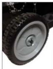
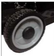
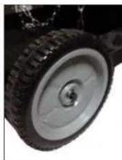
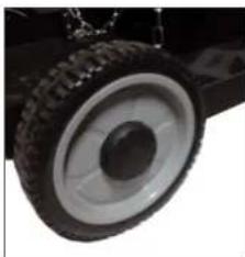
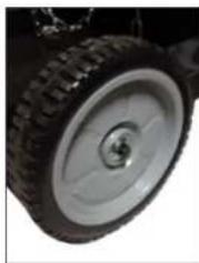
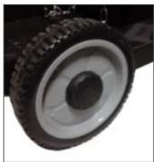
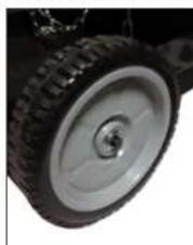
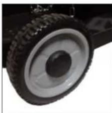
2.1. REAR WHEELS:
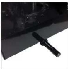
Slide axle through support tube on bottom of base plate.
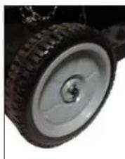
Fit wheel onto axle, slip over the end of axle.
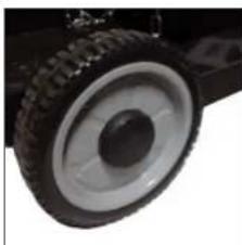
Insert cotter pin into hole at the end of the axle and bend in place.
Place protective cap over axle end and pin.
Repeat the above for other wheel.
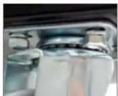
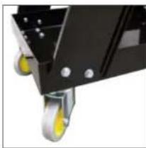
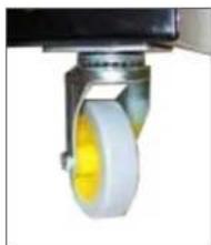
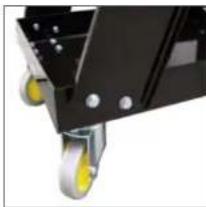
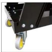
2.2. FRONT CASTER WHEELS:
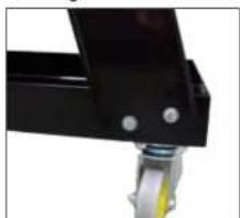
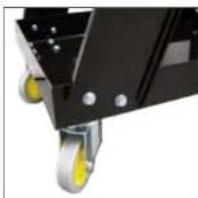
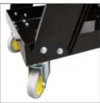
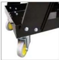
Align the swivel caster wheels with the 4 holes located on the front section of the base plate.
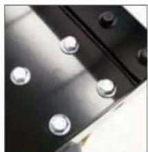
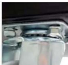
From the top of the shelf insert the bolt through the hole and secure it with the nut on the bottom side.
Repeat the above for other side.
Make sure all nuts and bolts are tight.
2.3. BACK VERTICAL SUPPORT PANEL:
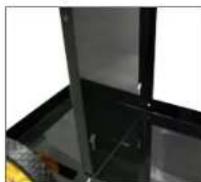
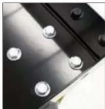
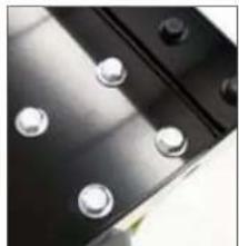
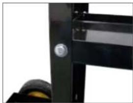
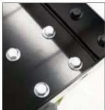
Align the holes in the bottom and the sides of the back vertical support panel with the holes in the sides and base plate.
Insert a bolt through center hole of the back vertical support panel and the bottom base plate and secure with a nut.
From the outside of the base plate, insert a bolt through left hole of the back vertical support panel and secure with nut.
Repeat the above on the other side.
Hand tighten bolts and nuts.
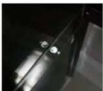
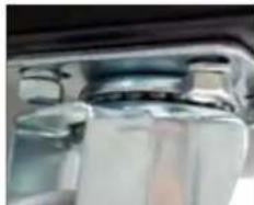
2.4. LEFT SUPPORT RAIL & RIGHT SUPPORT RAIL:
Align left bottom support rail on the front left side of bottom base plate.
From the outside of left support rail, insert bolt through each hole and secure on the inside with a nut.
Repeat the above on the right side.
Hand tighten bolts and nuts.
EN
EN
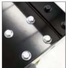
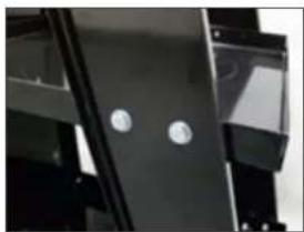
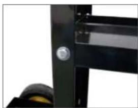
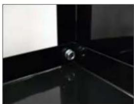
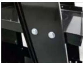
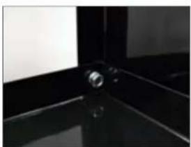
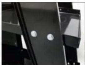
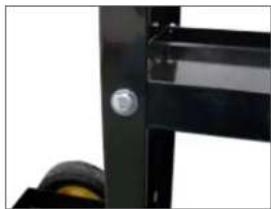
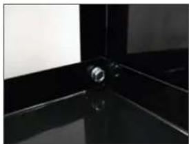
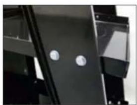
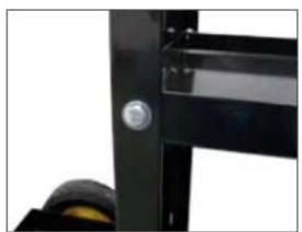
2.5. MIDDLE PLATE SHELF:
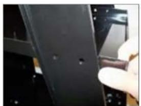
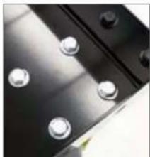
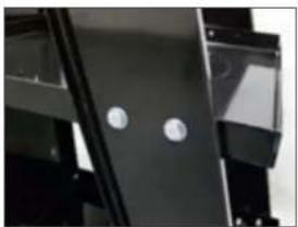
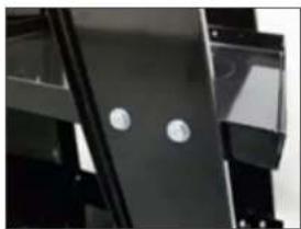
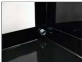
Align the holes of the middle plate to the holes in the left & right support rails and the back vertical support panel.
From the outside of the left / right support rails, insert a bolt through each of the holes and secure with a nut on the inside.
Align the 2 rear holes of the middle plate shelf with those of the back vertical support panel, insert a bolt through each of the holes and secure with a nut on the inside. Repeat the above on other side. Hand tighten bolts and nuts.

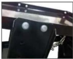
2.6. TOP PLATE SHELF:
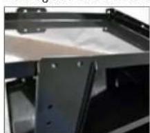
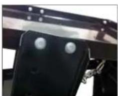
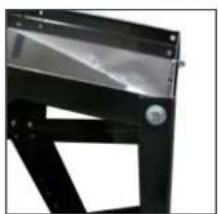
Align the holes of the top shelf plate with those of the left / right support rails and the back vertical support panel.
From outside of the left / right support rails insert a bolt through each hole and secure with a nut.
Repeat the above for all holes.
Hand tighten bolts and nuts.
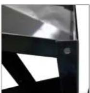
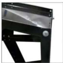
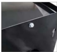
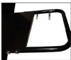
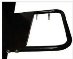
2.7. EASY PULL HANDLE:
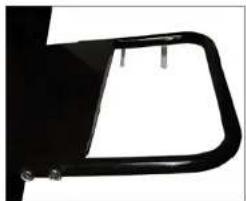
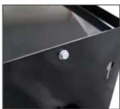
Align the holes of the handle with the holes on the top plate shelf.
From the outside of the shelf insert the longer bolts through each hole and secure with nut.
Repeat the above for all holes.
Hand tighten bolts and nuts.
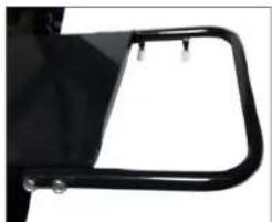
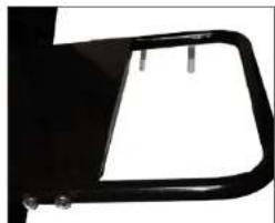
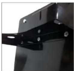
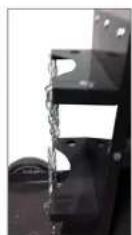
2.8. SAFETY CHAINS AND CYLINDER STATIONS:
Align the holes of the cylinder stations to the holes in the back vertical support panel.
From outside the stations, insert a bolt through each hole and secure with a nut. Repeat the above for all holes.
Hand tighten bolts and nuts.
Insert the safety chains into the keyholes cut into the stations.
EN
EN
2.9. CABLE HANGER HOOKS:
Align the cable hanger hooks with the holes of the left / right support rails, insert a bolt through each hole and secure with a nut.
Repeat the above for all holes. Hand tighten bolts and nuts.
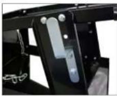
2.10. FINAL STEP:
In each of the above steps the bolts and nuts are only hand tight, this makes the assembly easier. However, all the bolts and nuts need to be tightened. Go back to each bolt and nut and tighten with wrenches to ensure a safe and complete unit.
3. MAINTENANCE:
Periodically tighten all of the bolts and nuts. Make sure the casters and wheels are free of all dirt or grease, etc.
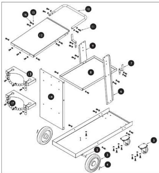
4. TROLLEY VIEW AND LIST OF THE PARTS:
| No. | Name Quantity | |
| 1 | Base plate 1 | |
| 2 | Axle 1 | |
| 3 | Wheel 2 | |
| 4 | Locking pin 2 | |
| 5 | Caster 2 | |
| 6 | Right rail support 1 | |
| 7 | Hook 2 | |
| 8 | Middle plate 1 | |
| 9 | Left rail support 1 | |
| 10 | Easy pull handle | 1 |
| 11 | Bolts M8x30 | 4 |
| 12 | Top plate | 1 |
| 13 | Chain link plate | 2 |
| 14 | Back vertical support panel | 1 |
| 15 | Nuts | 44 |
| 16 | Bolts M8x12 | 40 |
| 17 | Chain 2 |
STAMOS
WELDING GROUP
Wózek spawalniczy
INSTRUKCJA OBSŁUGI
PL
I. WAŻNE INFORMACJE DOTYCZĄCE BEZPIECZEŃSTWA
PL
PL
2.2. PRZEDNIE KÓŁKA SAMONASTAWNE:
2.4. LEWA SZYNA NOŚNA & PRAWA SZYNA NOŚNA:
2.5. PÓŁKA ŚRODKOWA:
PL
PL
2.6. GÓRNA PÓŁKA:
20
2.8. LANCUCHY ZABEZPIECZAJĄCE BUTLĘ ORAZ STANOWISKO BUTLI Z GAZEM:
2.10. DZIAŁANIA KOŃCOWE:
2.2. RUOTE ANTERIORI:
2.3. PARETE VERTICALE:
2.4. GUIDE PORTANTI DESTRA E SINISTRA:
2.5. SUPERFICIE D'APPOGGIO CENTRALE:
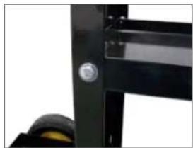
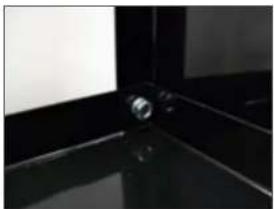
2.6. SUPERFICIE D'APPOGGIO SUPERIORE:

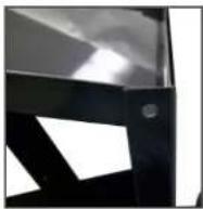
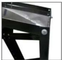
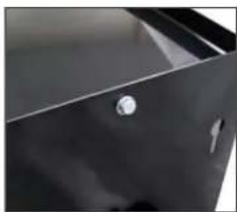
2.7. MANIGLIA:
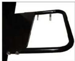
IT
IT
2.8. CATENE DI SICUREZZA E POSTAZIONE BOMBOLA A GAS:
2.9. GANCIO PER CAVI:
2.10. MISURE GENERALI:
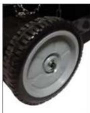
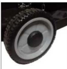
FR
FR
2.3 PAROIARRIÈREVERTICALE:
2.5 PLAQUE DE SUPPORT INTERMÉDIAIRE:
FR
FR
2.6 PLAQUE SUPERIEURE:
34
2.8 CHAÎNES DE MAINTIEN ET EMPLACEMENT DE LA BOUTEILLE DE GAZ:
2.9 CROCHETS DE MAINTIEN POUR TUYAUX / CÂBLES:
2.10 FINITION:

2.3. CHAPA TRASERA VERTICAL:
2.4. SOPORTES IZQUIERDO Y DERECHO:
2.5. ESTANTE CENTRAL:
40
2.6. ESTANTE SUPERIOR:
2.7.ASA:
41
Rev. 06.05.2022 Rev. 06.05.
ES
ES
2.8. CADENAS DE SEGURIDAD Y EMPLAZAMIENTO DE LAS BOMBO- NAS DE GAS:
2.9. GANCHOS PARA MANGUERAS Y CABLES:
43
Rev. 06.05.2022 Rev. 06.05.
NOTIZEN | NOTES NOTIZEN | NOTES
For the disposal of the device please consider and act according to the national and local rules and regulations.
CONTACT
expondo Polska sp. z o.o. sp. k.
- DE
- VORDERE SCHWENKRÄDER
- MITTLERE ABLAGE
- OBERE ABLAGE
- ASSEMBLY INSTRUCTIONS
- REAR WHEELS
- FRONT CASTER WHEELS
- BACK VERTICAL SUPPORT PANEL
- LEFT SUPPORT RAIL & RIGHT SUPPORT RAIL
- EN
- MIDDLE PLATE SHELF
- TOP PLATE SHELF
- EASY PULL HANDLE
- SAFETY CHAINS AND CYLINDER STATIONS
- CABLE HANGER HOOKS
- FINAL STEP
- MAINTENANCE
- TROLLEY VIEW AND LIST OF THE PARTS
- STAMOS
- WÓZEK SPAWALNICZY
- PL
- WAŻNE INFORMACJE DOTYCZĄCE BEZPIECZEŃSTWA
- PRZEDNIE KÓŁKA SAMONASTAWNE
- LEWA SZYNA NOŚNA & PRAWA SZYNA NOŚNA
- PÓŁKA ŚRODKOWA
- GÓRNA PÓŁKA
- LANCUCHY ZABEZPIECZAJĄCE BUTLĘ ORAZ STANOWISKO BUTLI Z GAZEM
- DZIAŁANIA KOŃCOWE
- RUOTE ANTERIORI
- PARETE VERTICALE
- GUIDE PORTANTI DESTRA E SINISTRA
- SUPERFICIE D'APPOGGIO CENTRALE
- SUPERFICIE D'APPOGGIO SUPERIORE
- MANIGLIA
- CATENE DI SICUREZZA E POSTAZIONE BOMBOLA A GAS
- GANCIO PER CAVI
- MISURE GENERALI
- FR
- 2.3 PAROIARRIÈREVERTICALE
- 2.5 PLAQUE DE SUPPORT INTERMÉDIAIRE
- 2.6 PLAQUE SUPERIEURE
- 2.8 CHAÎNES DE MAINTIEN ET EMPLACEMENT DE LA BOUTEILLE DE GAZ
- 2.9 CROCHETS DE MAINTIEN POUR TUYAUX / CÂBLES
- 2.10 FINITION
- CHAPA TRASERA VERTICAL
- SOPORTES IZQUIERDO Y DERECHO
- ESTANTE CENTRAL
- ESTANTE SUPERIOR
- 2.7.ASA
- CADENAS DE SEGURIDAD Y EMPLAZAMIENTO DE LAS BOMBO- NAS DE GAS
- GANCHOS PARA MANGUERAS Y CABLES
- CONTACT
Brand : Stamos
Model : S-WECA-1
Category : Industrial transport cart